1
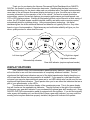
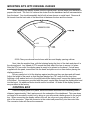
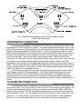
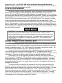
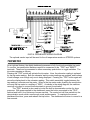
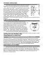
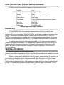
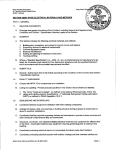
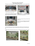
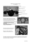
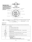
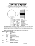
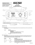
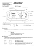
Dakota Digital
VACUUM FLUORESCENT DIGITAL DASHBOARD
The latest in digital dashboard technology for the
street rodder, car, and truck enthusiast.
INSTALLATION AND OPERATION MANUAL
Please read this before beginning installation or wiring.
MODELS STR2000, STR3B, STR3C,
STR4B, STR5B, STR6B, & STR6C
Thank you for purchasing the Vacuum Fluorescent Digital Dashboard from DAKOTA
DIGITAL, the leader in custom automotive electronics. Representing the latest electronics
dashboard technology for the street rodder and car enthusiast alike, the digital instrumentation
uses state of the art vacuum fluorescent display technology to give the driver up to date and
accurate information on the operation of his or her vehicle. As used in several production
automobiles, vacuum fluorescent displays give superior performance and visual appeal over
LCD or LED display systems. Emitting a blue/green light that can be filtered to a wide variety of
colors, the VFD system boasts excellent daytime visibility and while under computer control,
automatically dims for nighttime driving. Using microprocessor technology, the digital
dashboard gives the driver additional features and benefits not typically found on any other
brand or type of instrumentation. Digital accuracy and solid state reliability will give you, the
driver, quality service for miles down the road.
Left turn signal
Right turn signal
High beam indicator
Odometer/trip odometer
Gear shift indicator (requires optional sender)
DISPLAY FEATURES
Your DAKOTA DIGITAL instrumentation panel has many features, some of which you
will not be able to see until the instrumentation is completely wired and installed. The turn
signals and the high beam indicators are part of the digital speedometer display therefore you
will not see them before the instrumentation is installed. If your panel is a year specific street
rod panel you may also have additional green and or red LED's which also can be used for turn
signals and high beam indicators. These panels allow you to use either the indicators that are a
part of your speedometer, or the LED's.
The odometer is the bottom display of the speedometer area. This is the same display
that will function as the resettable trip-odometer. The digit furthest to the right of the odometer
will become your gear shift indicator if you purchased the optional gear shift sending unit. Every
DAKOTA DIGITAL instrumentation panel is equipped with this indicator. If you did not originally
order a gear shift sending unit, and would like to have a gear shift indicator, you may order the
sending unit at anytime and when properly installed, the gear shift indicator will operate.
WARNING
The vacuum fluorescent displays are made of glass and should be handled with care. Use extreme care
around the glass evacuation tubes (small tubes at the bottom of each display) as bumping them may cause
breakage and render the display useless.
MOUNTING DISPLAY SYSTEMS WITH SUBPANELS
When mounting instrumentation systems mounted to a Lexan subpanel, begin by
removing the subpanel from the aluminum. Cut an opening in the dash just smaller than the
outer dimensions of the aluminum panel. Remove all nuts and washers from the studs on the
back side of the panel and insert into the hole. Next, install four washers or clips and secure
with a nut on each. This is what holds the panel to the dashboard. Now, install a nut on each
stud and set the display panel in place over the studs. If the studs were bent slightly inward
from securing the aluminum panel, you may have to bend them outward to line up with the holes
on the lectern subpanel. Always lay the display panel aside when not in use to avoid
accidentally damaging the displays. Once aligned, secure it with an additional four nuts. Leave
a gap of no less than 1/8" between the display glass and the front lens material. Be careful not
to compress the glass against the front lens. Again, note that the displays are glass and should
be handled with care. Use extreme care around the glass evacuation tubes (small tubes at the
bottom of each display) as bumping them may cause breakage and render the display useless.
MOUNTING SYSTEMS WITH DISPLAYS MOUNTED TO ALUMINUM
When mounting year specific aluminum panel, cut an opening into the dashboard if
necessary and secure the entire panel with the instrumentation using the appropriate mounting
hardware. Some panels are set into the front of the dash while others are installed from the rear
of the dash. The exact mounting configuration will depend on what year car and panel you are
installing.
MOUNTING SINGLE LENS SYSTEMS
Your DAKOTA DIGITAL single lens system will come to you with a single plexiglass lens
and instrumentation that is mounted in an aluminum case. The lens and the instrumentation
have corresponding mounting holes. After you have affixed the mounting studs of your choice
to the backside of your dash, the lens piece should be slid over the studs followed by the display
system. The lens can be secured with either washers and nuts, or by a bead of RTV around the
back side of the lens and case. If RTV is used, the system will need to be held in place until it
has had time to cure. The lens should be tight against the aluminum display case.
MOUNTING KITS INTO ORIGINAL DASHES
When installing the display system into the original bezel, several steps must be taken to
prepare the bezel. The first is to remove the cluster from the dashboard and all instrumentation
from the bezel. You should essentially be left with a bare chrome or metal bezel. Remove all
felt inserts from the back side of the bezel that sit between the lens and the chrome.
55-56 Chevy car chrome bezel shown with lens and display opening outlines.
Next, take the supplied lens, with the lettering facing the front of the dash and place it in
the chrome bezel. Lay a bead of RTV around the back side of the lens to secure it in place.
After the RTV has cured, the display panel is ready to be placed on the bezel. If studs were
supplied with the panel, screw them into the bezel and place a nut on them before placing the
display system on it.
Be very careful not to hit the displays against anything as they are glass and will break.
Adjust the height of the panel so that the glass displays are 1/8" away from the front lens.
Applying a lock washer and nut to the studs behind the display panel, secure the display panel
to the bezel. If screws were provided with the panel, secure them through the display panel and
into the bezel. No additional holes should need to be drilled. All holes in the display systems
are pre-drilled at the factory.
CONTROL BOX
Once the display panel is in place, mount the control box within the connecting cable's
distance (approximately 3 feet) and secure to the underside of the dashboard. This case does
not have to be mounted to metal, but by doing so you will provide a better ground to the control
box. When connecting the display cable to the unit, be very sure to pay attention to the "up"
side of the connector. Align the connector in the socket and press firmly into the control box.
The connector locks will secure the connector.
Fig. 3 Instruments and features found in STR3C display systems
(55-56 Chevrolet shown)
SPEEDOMETER CONNECTION
The speedometer sender is connected to the transmission using the short adapter cable
supplied with the DAKOTA DIGITAL system. The cable supplied will typically be set up for use
with a GM transmission. GM transmissions use one cable and Ford and Chrysler use another.
Different cables are available from Dakota Digital. For 700-R4 transmissions with an internal
4000 pulse per mile generator (and no place to connect a speedometer cable) the terminals on
the plug in the transmission can be connected directly to the control box. The polarity of the
wires is not important. One wire connects to the terminal market "SPEED" and the other
connects to the "GROUND" terminal. Both wires should be connected directly to the control box
to eliminate any grounding problems causing erratic speed readings. Some newer GM
transmissions have an internal speed generator designed for use with anti-lock brake systems
(ABS). This has a high frequency signal that must pass through a speed buffer before it can be
used by the speedometer, cruise control, or ECM. This buffer can be purchased from Dakota
Digital if the vehicle is not equipped with one.
Some vehicles equipped with computer controlled fuel injection systems have a speed
signal already available in the wiring harness. Your Dakota Digital display system can use
either a 8000 pulse per mile or 4000 pulse per mile speed signal. To determine the wire
location and color consult your vehicle service manual or fuel injection system wiring guide.
Using this signal eliminates having to use the speedometer sender that was included with your
system.
TACHOMETER CONNECTION
The tachometer signal is connected to the terminal marked "TACH" on the control box for
the instrumentation. Run a single wire from the control box to the engine's ignition system. On
vehicles using a separate ignition coil, the wire connects to the terminal marked "DIST" (the
negative side) on the coil. For GM HEI ignition equipped motors, connect the tach wire to the
terminal marked "TACH". Do not connect the wire to the secondary or high voltage side of the
ignition coil. To ensure that the ignition system does not interfere with any other dashboard
functions, do not run the tachometer wire close to the other hookup lines, especially the
speedometer input. Also DO NOT USE solid core ignition wires with this dashboard
system. Solid core ignition wires cause a large amount of electromagnetic and radio frequency
interference which can disrupt system operation.
OIL & WATER SENDERS
Using the oil pressure, water temperature, and oil temperature senders included, mount
these to the motor using any necessary adapters and wire the senders to the control box
location. Do not use Teflon tape or thread sealant on the sender threads. Also, locate the
fuel sender signal wire and bring it to the terminal at the control box. Refer to the wiring diagram
when making the connections to these terminals. The sending unit ground terminal, marked
"SEND GND" can be connected directly to the "GROUND" terminal. This terminal is provided
so that a separate ground connection can be wired directly from the engine block. Some
vehicles will have a small voltage differential between the chassis ground and the engine block
ground. This can cause oil pressure and water temperature readings to be slightly high or low.
With the "SEND GND" terminal connected directly to the engine block, the readings will remain
accurate with ground voltage differentials up to 0.8 volts between the block and the point where
the control box is grounded.
WARNING
WARNING: If the separate ground connections are used, the negative terminal on
the battery must be connected directly to the engine block. If this is not done,
large voltage differences can develop between the ground terminals during engine
starting which may damage the control box. The voltage reading displayed by the
instrumentation’s voltmeter is the voltage between the "+ 12V" terminal and the
"SEND GND" terminal.
WIRING POWER TO THE CONTROL BOX
The +12V terminal should be connected to a circuit that is "on" when the key is in the run
or accessory position. The control box does not require any power to remember the odometer
mileage or calibration settings. The "GND" terminal is connected to the vehicle's ground. The
+12V terminal has an internal 2 amp fuse to protect the control box.
In order for the automatic dimming feature of the display system to operate properly, the
"DIM" terminal must be connected to the park light circuit. The display system will dim
whenever the "DIM" terminal has 12 volts applied to it. The display intensity for nighttime driving
is adjustable. There are two different ways to adjust the nighttime brightness intensity.
One method is to use the brightness adjustment located in a hole on the side of the
control box labeled "brightness". With the display system on and the headlights on, use a 1/8"
slotted screwdriver or a #1 Phillips screwdriver to turn the brightness adjustment. Clockwise
increases the display intensity. Do not attempt to turn the adjustment past either stop. Once
the desired intensity level is set, the display system will return to this brightness whenever the
headlights are turned on.
The second method for adjusting the brightness is by using the optional dash mount
intensity control. For the dash mount control to have full control of the display intensity, the
brightness adjustment on the side of the control box should be turned fully clockwise. The dash
mount intensity control is a 5000 ohm potentiometer, or 'pot'. It has three terminals on it.
Connect a wire from the center terminal on the pot to the terminal marked "INT.ADJ." Connect
a wire from the left terminal on the pot to ground. The third terminal is not used. The dash
mount control will allow full control of the display intensity when the headlights are on. When
the headlights are off, the display is always at full intensity.
DIGITAL DASHBOARD WIRING DIAGRAM
The optional sender input will be used for the oil temperature sender on STR2000 systems
.
TRIPMETER
As an optional feature, the digital dashboard possesses a fully functional resettable trip meter.
To use this, two push-button switches need to be connected to the "TRIP" and "RESET"
terminals. These can be connected to either momentary push-button or toggle switches. The
trip meter operates as follows:
Pressing the "TRIP" switch will activate the trip meter. Here, the odometer reading is replaced
by the trip meter reading. Both the odometer and trip meter readings are updated, and continue
to add mileage, even though only one is being displayed. Pressing the "TRIP" button again will
return the display back to the odometer reading. This switch essentially toggles between the
two readings, odometer and trip meter. When in the trip meter mode, pressing the reset button
will reset the trip meter to a reading of "000.0". As shown in the wiring diagram, the switches
used will only need to connect these terminals to ground for activation.
The "TRIP" terminal is also used to invoke the built in demonstration routine for show
purposes. With power applied to the dashboard, press the button connected to the "TRIP"
terminal and hold it for a minimum of seven seconds. The control unit will then switch into the
demonstration mode, which runs through a real world scenario. To reactivate the normal
dashboard functions, press and release the trip button. The dashboard will return to normal in a
few seconds.
OPTIONAL INDICATORS
High beam and turn signal indicators may also be connected.
Just connect the vehicle's high beam wire to the terminal marked
"HIGH", and connect the vehicle's turn signal wires to the terminals
marked "RIGHT" and "LEFT". Some year specific street rod panels
have LED lights mounted in the panel. These systems have two
sets of indicators. The LED's can be wired by connecting the black
wire to ground and the red wire to high beam or turn signal wires.
An optional gear shift indicator is also available. This uses an
optional Dakota Digital gear shift sending unit which is easily
connected to the control box terminals labeled "PARK", "REV",
"NTRL", "DRV", "2ND", and "1ST". Refer to the information card
supplied with the sender for more specific instructions, and to the
wiring diagram. Call for current pricing information, or check with your local DAKOTA DIGITAL
distributor.
CHECK ENGINE INDICATOR
For customers using computer controlled tune port
injected motors, there is a check engine indicator available. The
"check engine light" wire must be connected to the terminal
marked "check" on the control box. A "C" and an "E" will be
displayed and will flash one letter on each side of the
speedometer. There is also a provision in the control box to
allow a "dot" to be displayed to properly flash all of the engine
trouble codes. This dot will be found opposite of the high beam
indicator. The "check engine " indicator operates in the same
manner as the popular Chevrolet check engine indicator does.
This input may also be used as a brake warning indicator.
To do this, connect it to the wire from the brake pressure switch located on the master cylinder.
SETTING UP THE CONTROL BOX
SPEEDOMETER CALIBRATION
Speedometer calibration is accomplished by adjusting the "SPEED" ADJ" control on the
side of the control box. To accommodate different rear end ratios and tire sizes, the digital
speedometer of the dashboard has a wide range of calibration. Merely drive down the road with
a another vehicle going at a constant, know speed. Then using a 1/8" slotted or a #1 Phillips
screwdriver have someone adjust the pot (control) until the speedometer reads correctly. The
adjustment has ¾ rotation from stop to stop. Do not turn the adjustment past either stop.
This adjustment also calibrates the odometer to give accurate mileage readings.
BRIGHTNESS ADJUSTMENT
During normal operation, the dashboard displays are at full intensity. When the vehicle's
headlights are turned on, the intensity of the displays can be adjusted by the "Brightness"
control, which is located on the side of the control box. This should be done at night with the
lights on to activate the dimming circuit. The nighttime driving is adjustable two different ways.
Refer to the "WIRING POWER TO THE CONTROL BOX" section of this manual for the
instructions to wire both options.
Vacuum/Boost Connection
Software
chip
“DIP”
Programming
Switches
2 amp Fuse
(3AG)
Terminal
Strip
INTERNAL ADJUSTMENTS
While there are no user adjustable controls on the inside of the unit, there is a bank of
eight small switches which are used to set the dash up for different configurations. Your
instrumentation was set up at the factory for your particular configuration, but can easily be
adjusted to be compatible with different engines or fuel tank sending units by simply setting
these switches. To set the DIP switches (the small "computer" style switches), remove the four
screws on the top cover and slide the cover up and off. Note the location of the switches
numbered 1 through 8 and the numbering on each. Switches 1, 2, and 3 allow the control box to
be adjusted so the control box is compatible with many of the popular brands of fuel tank
sending units. You should always turn the dashboard off before making any changes to the
switch settings. After resetting any of the DIP switches, carefully replace the cover, being sure
to line it up properly on the edges.
Speed and Brightness adjustments have
¾ rotation from stop to stop.
Do not turn past either stop.
Speedometer adjustment – use to calibrate speed
Brightness control – use to adjust night brightness
Plug from display system
DIP SWITCH SETTINGS
The fuel sender selections are as follows:
Switch 1
2
3
sender
Off Off Off VDO, 10-180 ohms
Off Off On Ford, 73-10 ohms
Off On On Stewart Warner & Sun, 240-33 ohms
Off On Off GM, 0-90 ohms
On On Off GM, 0-30 ohms
*** IMPORTANT NOTE ***
The control boxes are normally configured for the Stewart Warner setting. This range will
cover the majority of the aftermarket senders available. If the fuel gauge does not operate
properly, check the DIP switch settings.
The tachometer range is selected as follows:
Switch 4
range
off
0 - 6000 RPM
on
0 - 8000 RPM
Engine selection is as follows:
Switch 5
6
# of cylinders
Off Off 4 cylinder
Off On 6 cylinder
On Off 8 cylinder
Switch #7 allows you to change the instrumentation from Standard English to Metric readings.
The switch should be in the "off" position for the Standard English readings, and in the "on"
position when the metric equivalents are desired.
WARNING SYSTEM
The digital dashboard system incorporates an "idiot" light warning system that alerts the
driver to any dangerous conditions or conditions that may indicate vehicle trouble. The fuel
reading begins flashing when the reading gets below 10%. Voltage levels below 11 volts will
prompt a warning as well will water temperatures above 250 degrees Fahrenheit. If the oil
pressure drops below 10 PSI with the engine running, the reading flashes to warn the driver of
possible serious engine trouble. These levels are built into the software and are not user
changeable.
NOTE; A reading of "--" or "---" on any of the displays (instruments) indicate that the
particular sending unit is not connected properly.
WIRE COLOR CODE FOR GM WIRING HARNESS
On the connector that originally plugged into the instrument cluster:
Function
Color
------------------------------------------------------------------+12 volt
Pink/Black or Pink
Ground
Black
Oil sender
Tan or no wire if mechanical
Water sender
Dark green
Fuel sender
Pink or light brown (should not have power)
Left turn
Light blue
Right turn
Dark blue
High beam
Light green
Brake warn
Tan/white or tan
(this will light check engine indicator)
WARRANTY
All DAKOTA DIGITAL instruments are warranted free of defects in material and
workmanship for the life of the vehicle in which they are originally installed. In the event of a
problem with one of our products, DAKOTA DIGITAL will replace or repair the instrument at no
charge. (The decision to repair or replace is solely that of DAKOTA DIGITAL. DAKOTA
DIGITAL is not responsible for shipping costs of products returned under warranty or for labor
charges for product installation and removal.) This warranty becomes invalid if the product is
misused, altered or installed incorrectly.
The above warranties, both expressed and implied, do not cover damages caused by
improper assembly, misuse, abuse, fire, unauthorized modifications, floods or acts of God, or
reimbursement of customer or shop time. The extent of the warranty is limited only to the
product and does not cover any loss or damaged to vehicle, equipment, or non-DAKOTA
DIGITAL products.
SERVICE AND REPAIR
DAKOTA DIGITAL offers complete service and repair of its product line. In addition, free
technical consultation is available to help you work through any questions or problems you may
be having installing one of our units.
Should you ever need to send the unit back for repairs, please package the product in a
good quality box along with plenty of packing material. Ship the product by UPS or insured
Parcel Post. Be sure to include a complete description of the problem, your full name and
address (street address preferred), and a telephone number where you can be reached during
the day. An authorization number for products being return for repair is not needed. Do not
send any money. We will bill you for the repair charges.
TROUBLESHOOTING GUIDE
This is a list of some problems and their solutions which may be encountered when installing your instrumentation
system. If you cannot determine what the problem is or how to solve it, please call our technical assistance line
(605) 332-6513.
* A note on vehicle grounding. *
The most common cause of problems with electric gauges is poor ground connections. The engine block
has the highest ground currents of any point in the vehicle. The ignition system, electric gauge senders, starter,
alternator, etc. all use the engine block for a ground point. Since the alternator is grounded directly to the engine
block all ground currents in the entire vehicle must pass through the engine block while the engine is running. A
weak or loose connection can cause all kinds of random problems that may difficult to track down. The engine
block should have heavy ground straps to both the chassis and the body. The main negative cable from the battery
should be connected directly to the engine block.
Symptom
Possible Problem
Solution
----------------------------------------------------------------------------------------------------------------------------------System does not light up.
Control box may not be getting
Check if the control box has
power.
12 volts connected to it.
Check the fuse inside the control
box. If it is blown, replace with a
2 amp fuse.
The display system may not be
Insert the connector on the
getting power.
display system wiring harness
into the slot on the side of the
control box. Be sure the pins
line up properly.
Check the display system wiring
harness for broken or cut wires.
The control box may have
Return the control box to Dakota
an internal problem
Digital with a description of the
problem and a phone number.
A display shows dashes.
The sending unit for that display
is not connected to the control
box.
Check the wire from sending unit
to the control box for breaks.
Make sure that the sending unit is
wired to the correct terminal.
Make sure the sending unit is
grounded properly.
One display does not
light up.
If the circle in the upper right
corner of the display is white,
the display is cracked or broken
Return the display panel to
Dakota Digital for repair. Include
a phone number and address.
The tachometer will not
show a reading.
The control box is not connected
to the engine properly
Make sure the control box is
connected to your particular
system properly.
Symptom
Possible Problem
Solution
----------------------------------------------------------------------------------------------------------------------------------The tachometer reading
The tachometer signal wire is
Check the connections at both
is incorrect.
loose or broken.
ends of the wire.
The control box is not set up for
Refer to the Internal Adjustments
the proper number of cylinders
section of the installation manual
or the proper tach range.
to set the control box properly.
The speedometer will
not show a reading.
The speed sending unit is not
connected to the control box
properly.
The speed sending unit being
used is not compatible with the
control box.
The speed sending unit is not
connected to the transmission
properly.
The sending unit wire is picking
up noise from nearby wires.
The fuel display reads
backwards, incorrectly,
or does not change.
The control box may be set for
the wrong type of fuel sender.
The fuel sender may not be
connected to the control box
properly.
The fuel sender may not be
operating properly.
The fuel sender may have a
non-standard resistance
range.
The oil or water display
reading is incorrect.
The engine block may not be
grounded to the chassis frame
properly.
The sending unit wire is picking
up noise from nearby wires.
The sending unit is not
compatible with the control box
The sending unit has failed.
Check that both speed sending
unit wires are connected to the
control box properly.
Use the speed sending unit
supplied with the display
system.
Check that sender is mounted
properly.
Check that transmission has the
appropriate internal parts.
Isolate the sending unit wire from
motor and ignition wires.
Refer to the Internal Adjustments
section of the installation manual
to ensure that the settings match
your fuel sender.
Check the connections at both
ends of the fuel sender wire.
Make sure the fuel sender is
grounded properly.
Check the fuel sending unit with
a mechanical gauge or an
electrical multi-meter.
If the proper resistance range
setting is not available with
the control box settings, replace
the fuel sender with a different
style.
Connect the SEND GND terminal
directly to the engine block.
Read the warnings in the manual
Use a braided ground strap to
ground the engine block to the
chassis.
Isolate the sending unit wire from
motor and ignition wires.
Use the sending unit provided
the display system.
Return the sending unit to
Dakota Digital for replacement.
Symptom
Possible Problem
Solution
----------------------------------------------------------------------------------------------------------------------------------The gear shift indicator
The optional gear shift sending
Connect the sending unit to the
does not light up.
unit is not connected to the
control box using the
control box.
instructions supplied with the
sending unit.
The gear shift indicator
does not operate
properly.
The gear shift sending unit
is not connected properly.
Check the connections to the
transmission linkage and to
the control box.
Connect 12 volts to the sending
unit power wire.
The colored bulbs in
the display panel for
turn signals and high
beam do not light up.
(not found on all units)
The LED bulbs are not
connected into the auto's
electrical system.
(these are not wired into the
display system control box)
Connect the wires found on the
back of the aluminum panel
to your cars electrical system
as explained in the Optional
Indicators section of the manual.
The internal turn signal
and high beam
indicators do not light up.
The control box is not connected
to the vehicle's electrical
system properly.
Check the wires connected to the
HIGH, LEFT, and RIGHT
terminals on the control box.
The check engine
indicator does not
operate properly.
The control box is not connected
to a TPI control module.
This feature is designed to work
with engine control systems that
provide an active low signal.
The check engine
indicator stays on
all of the time.
The Engine Control Module
(ECM) needs to see the
load of a light connected to it.
Connect a light or similar load
to the ECM along with the
control box.
Trip select and trip reset
functions do not operate
properly.
Select and reset switches are
not connected to the control
box.
Momentary push-button or toggle
switches must be connected to
the TRIP and RESET terminals
as described in the Trip meter
section of the installation manual
The switch terminal connected
to the control box should
normally be open. When the
the switch is activated, the
terminal should make contact
to ground.
Disconnect or replace the trip
select switch.
The wrong type of switch is
being used.
The display system starts
up in the demonstration
mode and remains in it.
The TRIP terminal is constantly
connected to ground.
4510 W. 61ST St. N., Sioux Falls, SD 57107
Phone: (605) 332-6513 FAX: (605) 339-4106
www.dakotadigital.com
[email protected]
©Copyright 2002 Dakota Digital Inc.