1
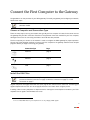
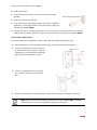
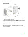
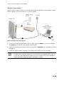
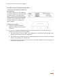
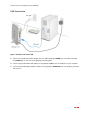
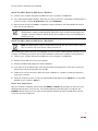
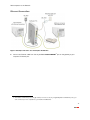
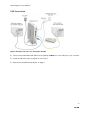
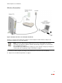
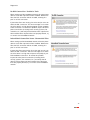
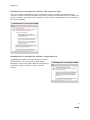
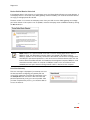
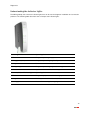
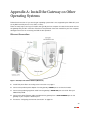
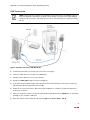
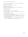
2Wire Gateway
Installation Guide
For 2701
Notice to Users
©2006 2Wire, Inc. All rights reserved. This manual in whole or in part, may not be reproduced, translated, or reduced to any machinereadable form without prior written approval.
2WIRE PROVIDES NO WARRANTY WITH REGARD TO THIS MANUAL, THE SOFTWARE, OR OTHER INFORMATION CONTAINED HEREIN AND
HEREBY EXPRESSLY DISCLAIMS ANY IMPLIED WARRANTIES OF MERCHANTABILITY OR FITNESS FOR ANY PARTICULAR PURPOSE WITH
REGARD TO THIS MANUAL, THE SOFTWARE, OR SUCH OTHER INFORMATION, IN NO EVENT SHALL 2WIRE, INC. BE LIABLE FOR ANY
INCIDENTAL, CONSEQUENTIAL, OR SPECIAL DAMAGES, WHETHER BASED ON TORT, CONTRACT, OR OTHERWISE, ARISING OUT OF OR
IN CONNECTION WITH THIS MANUAL, THE SOFTWARE, OR OTHER INFORMATION CONTAINED HEREIN OR THE USE THEREOF.
2Wire, Inc. reserves the right to make any modification to this manual or the information contained herein at any time without notice.
The software described herein is governed by the terms of a separate user license agreement.
Updates and additions to software may require an additional charge. Subscriptions to online service providers may require a fee and
credit card information. Financial services may require prior arrangements with participating financial institutions.
2Wire, the 2Wire logo, and HomePortal are registered trademarks, and HyperG, Greenlight, FullPass, and GuestPass are trademarks
of 2Wire, Inc. All other trademarks are trademarks of their respective owners.
5100-000413-000 Rev A
Contents
Getting Started 1
Remove or Disable Conflicting Applications 1
Check Your Computer’s Browser and System Requirements 1
Browser Requirements 1
System Requirements 1
Connect the First Computer to the Gateway 2
Choose a Computer and Connection Type 2
Install the DSL Filter 2
For Wall-Mounted Phones 3
Ethernet Connection 4
Check Your Connections 4
Wireless Connection 5
Non-2Wire Wireless Adapter Configuration 6
USB Connection 7
Install the 2Wire Gateway USB Driver - Windows 8
Install the 2Wire Gateway USB Driver - Macintosh 8
Check Your Connections 8
Run the 2Wire Setup Wizard 9
Windows XP/2K/ME/98SE 9
Macintosh OS 10.1.4/10.1.5/10.2.0 - 10.2.8/10.3.3 - 10.3.8 9
Add Computers to the Network 10
Ethernet Connection 11
USB Connection 12
Wireless Connection 13
Diagnostics 14
Understanding Broadband Redirect Messages 14
Excessive Sessions Warning 14
Invalid Customer Information (PPP) 14
No DSL Connection - Unable to Train 15
Intermittent Connection Issue - Uncanceled Echo 15
Broadband Link is Currently Not Available - DSL Connection Issue 16
Broadband Link is Currently Not Available - Connection Error 16
Router Behind Router Detected 17
Provision Gateway 17
Understanding the Indicator Lights 18
Appendix A: Install the Gateway on Other Operating Systems 20
Ethernet Connection 20
USB Connection 21
Configuring the Internet Connection 22
Regulatory Information 23
Getting Started
Remove or Disable Conflicting Applications
Internet sharing software and PC based firewall applications typically interfere with the 2Wire gateway, and
should be removed or disabled before you install the gateway. The 2Wire gateway provides the same
features as the products listed below.
If you have any of the following (or similar) applications installed on your computers, remove or disable
them according to the manufacturer’s instructions before proceeding.
Internet Sharing Applications
Proxy Software
Security Software
Microsoft Internet Connection Sharing
Wingate
Norton Internet Security
Intel Anypoint ISS
Sygate
Black Ice
3Com HomeClick
Zone Alarm
Check Your Computer’s Browser and System Requirements
Verify that your computers meet the following minimum requirements:
Browser Requirements
Windows: Microsoft Internet Explorer 5.5 or higher (included on the 2Wire CD), Netscape Navigator 4.7 or
higher, or Firefox 1.0 or higher.
Macintosh: Safari 1.0, Microsoft Internet Explorer 5.0, or Netscape 4.74 or higher.
System Requirements
•
5 MB of available hard disk space for 2Wire gateway software.
•
Windows XP, Windows 2000, Windows NT 4.0 with Service Pack 6, Windows ME, Windows 98/98SE,
or Mac OS 8.6 or higher.
•
Network adapter (such as Ethernet, USB, or 802.11b/g wireless).
1
Connect the First Computer to the Gateway
Congratulations on the purchase of your 2Wire gateway. To install your gateway and configure your network,
follow these steps.
Note: Features for different models may vary. Product details will be specified for each
particular model.
Choose a Computer and Connection Type
There are many ways to set up your network, but typically the first computer is located in the same room as
the gateway and your DSL connection. Ethernet is the preferred connection method for your first computer,
although instructions for connecting via wireless and USB are also provided.
The first computer you connect to the network is used to configure the 2Wire gateway for proper operation.
Choose one of the following methods to connect your first computer to the gateway. Save and close all open
programs before you begin connecting your gateway.
Connection Type
Page
Ethernet
page 4
Wireless
page 5
USB
page 7
Install the DSL Filter
Note: New DSL customers only. Existing DSL customers with filters already installed should
proceed to Ethernet Connection on page 4, Wireless Connection on page 5, or USB
Connection on page 7.
Regular telephone and Digital Subscriber Line (DSL) signals are carried over the same line. Converting your
regular telephone line to DSL can cause high-pitched tones and static when using the phone.
Installing a filter on every telephone or telephone device sharing the same telephone number as your DSL1
separates these signals and eliminates the noise.
1. Do not install DSL filters if your telephone line is only carrying a DSL signal.
2
Connect the First Computer to the Gateway
To install the DSL filter:
1.
Locate the phone jack where you want to connect your 2Wire
gateway.
2.
Insert the DSL filter into the jack.
3.
If you have a phone, answering machine, fax machine, satellite TV
equipment, or other phone device in this jack location, plug it into
the filter port labeled PHONE.
4.
Install a DSL filter on all other phone devices in your house (such as dial-up modems, fax machines,
caller ID devices, and set top boxes). Plug each of these devices into the filter port labeled PHONE.
For Wall-Mounted Phones
If you have a wall-mounted telephone, install a wall-mount DSL filter following these steps.
1.
Lift the telephone from the wall pegs and disconnect the phone cord from the wall jack.
2.
Connect the telephone cord from the back
of the DSL filter into the wall jack. Align the
keyhole slots on the filter with the wall plate
pegs and press down gently to secure.
3.
Connect the telephone cord to the phone
jack located on the front of the mounted
filter.
4.
Attach the telephone to the mounting pegs on the DSL filter and your installation is complete.
Note: The extra phone jack located at the bottom of the filter (labeled LINE) is provided
should you wish to connect your gateway at this phone connection.
3
Connect the First Computer to the Gateway
Ethernet Connection
Figure 1. Gateway Connected Via Ethernet
1.
Connect the provided power adapter from the gateway’s POWER port to an electrical outlet. The POWER
light on the front of the gateway should be green.
2.
Connect the provided gray phone cable from the gateway’s PHONE LINE port to the DSL filter jack labeled
DSL/HPNA.
3.
Connect the yellow Ethernet cable provided with the gateway from any available LOCAL ETHERNET port on
the gateway to your computer’s Ethernet port.
Check Your Connections
With your computer completely started, verify the POWER and ETHERNET indicator lights on the front of the
2Wire gateway are green. If they are not, see “Understanding the Indicator Lights” on page 18. The
INTERNET indicator light will not turn green until the gateway software has been installed and an Internet
connection has been established.
4
Connect the First Computer to the Gateway
Wireless Connection
Requires wireless-enabled notebook or a computer with an 802.11b/g wireless network adapter installed.
Wireless adapters can be purchased from your service provider.
Figure 2. Gateway Connected Via Wireless
1.
Connect the provided AC power adapter from the 2Wire gateway’s POWER port to an electrical outlet.
The POWER light on the front of the gateway should be green.
2.
Connect the provided gray telephone cable from the gateway’s PHONE LINE port to a telephone jack with
DSL service.
3.
Install your wireless adapter according to the manufacturer’s instructions (see note below).
Note: If you use a 2Wire wireless adapter (PC card or USB adapter) for wireless networking,
the 2Wire CD automatically configures it to communicate with the gateway during setup. If
you are NOT using a 2Wire wireless adapter, you must manually configure your adapter to
communicate with the gateway using the information on page 6.
5
Connect the First Computer to the Gateway
Non-2Wire Wireless Adapter Configuration
Locating the Serial Number and Wireless
Encryption Key
The serial number of your 2Wire gateway is
used as the network name (SSID). Beneath
the serial number is a ten-digit number
which is used as the encryption key. These
are located on the bottom of your gateway
(shown in horizontal orientation). You will
need this information to configure your
wireless adapter.
Configuring the Adapter
1. Install and configure your wireless
adapter according to the manufacturer’s
instructions.
2.
Use the network adapter configuration software or Windows network connection wizard to set the
network name (SSID) and encryption key (WEP).
a. The network name is the word “2WIRE” (in all capital letters), followed by the last three digits of the
gateway serial number (for example, 2WIRE110).
b. The encryption key is a 64-bit hex value, located beneath the bar code on the bottom of the 2Wire
gateway. In the example, it is 4119627022.
c.
For Mac OS X users, you may need to enter the “$” character at the beginning of the encryption key
(for example, $4119627022).
6
Connect the First Computer to the Gateway
USB Connection
Figure 3. Gateway Connected Via USB
1.
Connect the provided AC power adapter from the 2Wire gateway’s POWER port to an electrical outlet.
The POWER light on the front of the gateway should be green.
2.
Connect the provided blue USB cable from the gateway’s USB port to the USB port on your computer.
3.
Connect the provided gray telephone cable from the gateway’s PHONE LINE port to a telephone jack with
DSL service.
7
Connect the First Computer to the Gateway
Install the 2Wire Gateway USB Driver - Windows
1.
Power on your computer and place the 2Wire CD in your computer’s CD-ROM drive.
2.
If the Add Hardware Wizard displays, follow the on-screen instructions. If prompted to identify where to
search for drivers, deselect Floppy Disk drive and check CD-ROM drive.
3.
After the driver installs click Finish to complete the driver installation. The Setup Wizard will resume
when your PC has rebooted.
Note: Microsoft Windows 98 users may be prompted to insert the Windows 98 installation
CD-ROM after installing the 2Wire gateway USB drivers. After the Windows 98 updates are
complete, remove the Windows 98 CD and reinsert the 2Wire CD into your CD-ROM prior to
rebooting your PC.
Install the 2Wire Gateway USB Driver - Macintosh
Note: The 2Wire gateway supports USB for Macintosh OS 8.6, 9.2, 10.1.4, 10.1.5, 10.2.0,
10.2.1 to 10.2.6, 10.3.3 to 10.3.9, 10.4.0, and 10.4.1.
Before making your USB connection to the gateway, you must install the 2Wire gateway USB driver on your
computer. The following instructions are for USB installation on Macintosh computers running OS 10.2.
1.
Power on your computer and place the 2Wire CD in your computer’s CD-ROM drive.
2.
Double-click the 2Wire CD icon on your desktop.
3.
Double-click 2Wire USB to begin the driver installation.
4.
If you have set up an administrator name and password, the Authenticate screen opens. Enter your
administrator name and password and click OK.
5.
Follow the on-screen instructions. When the driver installation is complete, you will be prompted to
restart your computer.
6.
After your computer restarts, connect the provided blue USB cable from the USB-PC port on the 2Wire
gateway to your computer’s USB port.
Check Your Connections
With your computer completely started, verify the POWER and USB-PC indicator lights on the front of the
2Wire gateway are green. If they are not, see “Understanding the Indicator Lights” on page 18. The
INTERNET indicator light will not turn green until the gateway software has been installed and an Internet
connection has been established.
8
Run the 2Wire Setup Wizard
Windows XP/2K/ME/98SE
1.
2.
Insert the 2Wire CD and follow the on-screen instructions. If the 2Wire Setup Wizard does not
automatically start:
−
Double-click the My Computer icon located on the desktop.
−
Double-click the icon that corresponds to your CD-ROM drive.
−
Double-click Setup.exe and follow the on-screen instructions.
If prompted by the Setup Wizard, enter the 20-digit key code you received from your service provider.
If you were not provided with a key code, contact your service provider.
Macintosh OS 10.1.4/10.1.5/10.2.0 - 10.2.8/10.3.3 - 10.3.8
Note: MAC OS 9.X AND OTHER OPERATING SYSTEM USERS: Users running Mac OS 9.X and
operating systems other than those stated above must perform a manual configuration of
the gateway. Refer to “Appendix A: Install the Gateway on Other Operating Systems” on
page 20 for step-by-step instructions.
1.
Insert the 2Wire CD.
2.
Double-click the 2Wire icon.
3.
Double-click the 2Wire Setup Wizard icon.
4.
If prompted by the Setup Wizard, enter the 20-digit key code you received from your service provider.
If you were not provided with a key code, contact your service provider.
9
Add Computers to the Network
After your first computer is connected to the 2Wire gateway and your Internet connection has been
established, you can connect other computers to the network.
Use any of the following methods to connect additional computers to your network.
Connection Type
Page
Ethernet
page 11
USB
page 12
Wireless
page 13
10
Add Computers to the Network
Ethernet Connection
Figure 4. Gateway Connected to Second Computer Via Ethernet
1.
Connect an Ethernet cable from the any available LOCAL ETHERNET1 port on the gateway to your
computer’s Ethernet port.
1. The number of Ethernet ports vary by model (from one to four). If your gateway has four Ethernet ports, you
can connect up to four computers to your network via Ethernet.
11
Add Computers to the Network
USB Connection
Figure 5. Gateway Connected to Second Computer Via USB
1.
Connect the provided blue USB cable from the gateway’s USB-PC port to the USB port on your computer.
2.
Install the USB driver (refer to page 8 for instructions).
3.
Repeat “Run the 2Wire Setup Wizard” on page 9.
12
Add Computers to the Network
Wireless Connection
Figure 6. Gateway Connected to Second Computer Via Wireless
Requires a computer with an 802.11b/g wireless network adapter installed. Wireless adapters are
purchased separately from the 2Wire gateway.
Note: If you use a 2Wire wireless adapter (PCI, PC card, or USB adapter) for wireless
networking, the gateway installation software automatically configures it to communicate
with the gateway during setup.
If you are NOT using a 2Wire wireless adapter, you must manually configure your adapter to
communicate with the gateway using the information on page 6.
1.
Install your wireless adapter according to the manufacturer’s instructions (see note above).
2.
Repeat “Run the 2Wire Setup Wizard” on page 9.
13
Diagnostics
Note: Broadband Redirect Messages are visible only if they have been enabled by your
service provider, and the physical appearance may vary from the examples shown.
Understanding Broadband Redirect Messages
If the 2Wire gateway detects a connection problem or an intermittent service error, it generates an error or
alert (Broadband Redirect Message) and displays the message within your Web browser. The following
messages contain information that can help you resolve some of the most common installation or network
conflicts.
Excessive Sessions Warning
This error message typically occurs when your PC has been infected
with the Blaster Virus or similar agent. The error message appears
because too many simultaneous Internet sessions are opened,
which impairs both network and PC performance. Check the PC with
an anti-virus program using the latest virus updates to identify and
remove the infection.
There may be cases where certain applications running on a PC
mimic the excessive session characteristics, creating a false
positive error condition. If you are certain that no viruses are
present on the PC, enable the Do not show me excessive session
warnings in the future checkbox.
Invalid Customer Information (PPP)
This error message results from an incorrect PPP username and/or
password. Click the Set Up Now button to re-enter the correct PPP
information and attempt to connect to the broadband network.
14
Diagnostics
No DSL Connection - Unable to Train
When setting up a DSL broadband network, all active phone
devices must have a phone line filter installed. Without the
filter, the DSL connection will be unstable, resulting in a
poor or no DSL connection.
If phone line filters are missing, line noise and/or echo can
affect the DSL connection. This error message occurs when
the noise level is so high that the gateway cannot establish
a DSL connection. To resolve this problem, inspect all active
phone connections (including home security systems, fax
machines, etc.) and verify that all devices have a phone line
filter installed. Once all phone lines are properly filtered, try
to connect to the broadband network.
Intermittent Connection Issue - Uncanceled Echo
When setting up a DSL broadband network, all active phone
devices must have a phone line filter installed. Without the
filter, the DSL connection will be unstable, resulting in a
poor or no DSL connection.
If phone line filters are missing, line noise and/or echo can
affect the DSL connection. This error message occurs when
the noise level is so high that it impacts the quality of your
DSL broadband connection. To resolve this problem,
inspect all active phone connections (including home
security systems, fax machines, etc.) and verify that all
devices have a phone line filter installed. Once all phone
lines are properly filtered, try to connect to the broadband
network.
15
Diagnostics
Broadband Link is Currently Not Available - DSL Connection Issue
This error message is displayed because the gateway was unable to establish a broadband network
connection. Check to ensure that all cables are correctly connected, and the cable end securely attached to
the port. In addition, verify that you are connecting on or after the date specified by your service provider for
DSL service availability.
Broadband Link is Currently Not Available - Connection Error
The gateway was unable to communicate with the service
provider network. This could be due to failed network
equipment or a temporary outage. When the Internet light on
the gateway is green, attempt to connect to the DSL
network.
16
Diagnostics
Router Behind Router Detected
If the gateway detects the presence of a third-party router, the Router Behind Router error page displays. If
a third-party router is connected to the 2Wire gateway, network instability can result because both devices
are trying to manage private IPs via NAT.
The best solution is to remove the third-party router from your LAN since the 2Wire gateway can manage
your home network. If this option is not acceptable, move the third-party router to DMZPlus Mode by clicking
the Resolve button..
Note: DMZplus is a special firewall mode that is used for hosting applications. When in
DMZplus mode, the designated computer shares your gateway’s IP address (Router
Address), appears as if it is directly connected to the Internet, has all of the unassigned TCP
and UDP ports opened and pointed to it, and can receive unsolicited network traffic from the
Internet. Because all filtered traffic is forwarded to the designated computer, DMZplus mode
should be used with caution. A computer in DMZplus mode is less secure because all
available ports are open and all incoming Internet traffic is directed to this computer.
Provision Gateway
This error message is displayed if you attempt to access
the Internet before configuring your gateway with the
correct PPP credentials (username and password). Click
the Set Up Now button to enter the PPP username and
password provided to you by your service provider. After
you have completed this process, you should be able to
access the Internet.
17
Diagnostics
Understanding the Indicator Lights
The 2Wire gateway has numerous indicator lights that can be used to diagnose installation and connection
problems. The following table describes how to interpret the indicator lights.
Power Light
Operating State
OFF
The gateway is not getting power.
Blinking green (slow)
The gateway is undergoing POST (power-on self test).
Solid green
Power is on.
Blinking orange
The gateway is undergoing a software upgrade.
Solid red
System error. Contact Technical Support.
Ethernet, USB, or Wireless Light
Operating State
OFF
The gateway is powered off or booting up.
Solid green
Device(s) connected via Ethernet, USB, or Wireless.
Flickering green
Data traffic is coming into or going out from the network.
18
Diagnostics
DSL Light
Operating State
OFF
The gateway is powered off or booting up.
Blinking green (slow)
The gateway is attempting to establish a connection to your
broadband service(s).
Blinking green (fast)
The gateway has been unable to connect to the DSL signal
for more than three minutes.
Solid green
The gateway is fully connected to your broadband
service(s).
Internet Light
Operating State
OFF
The gateway has been unable to detect a DSL signal.
DSL signal detected; the gateway is attempting to train.
Blinking green (fast)
The gateway is attempting to establish a connection to your
broadband service(s).
Solid red
The gateway cannot connect to your broadband service.
19
Appendix A: Install the Gateway on Other
Operating Systems
Follow these instructions if you are using an operating system that is not supported by the 2Wire CD (such
as any Macintosh OS prior to 10.2, UNIX, or Linux).
There are many ways to set up your network, but typically the first computer is located in the same room as
the gateway and your DSL connection. Ethernet is the preferred connection method for your first computer,
although instructions for connecting via USB are also provided.
Ethernet Connection
Figure 7. Gateway Connected Via Ethernet (Macintosh)
1.
Install DSL phone filters according to the instructions on page 2.
2.
Connect the provided power adapter from the gateway’s POWER port to an electrical outlet.
3.
Connect the provided gray phone cable from the gateway’s PHONE LINE port to the DSL filter jack
labeled DSL/HPNA.
4.
Connect the yellow Ethernet cable provided with the gateway from a LOCAL ETHERNET port on the
gateway to your computer’s Ethernet port.
5.
Proceed to “Configuring the Internet Connection” on page 22.
20
Appendix A: Install the Gateway on Other Operating Systems
USB Connection
Note: Connecting your computer to the gateway using USB requires an available USB port.
Only one Windows or Macintosh computer can be directly connected to the 2Wire gateway
using the USB connection. The following instructions are for Macintosh computers running
OS 9.x.
Figure 8. Gateway Connected Via USB (Macintosh)
1.
Install DSL phone filters according to the instructions on page 2.
2.
Insert the 2Wire CD in the computer’s CD-ROM drive.
3.
Double-click the 2Wire CD icon on your desktop.
4.
Double-click 2Wire USB to begin the driver installation.
5.
If you have set up an administrator name and password, the Authenticate screen opens. Enter your
administrator name and password and click OK.
6.
Follow the on-screen instructions. When the driver installation is complete, you will be prompted to
restart your computer.
7.
After your computer restarts, connect the provided blue USB cable from the USB-PC port on the 2Wire
gateway to your computer’s USB port.
8.
Open the network Control Panel by selecting the Apple icon > Control Panel > TCP/IP.
21
Appendix A: Install the Gateway on Other Operating Systems
9.
Verify that “Connect Via: 2Wire USB Remote NDIS…” is selected to set the network adapter as active.
10. Click Save to complete your installation.
11. Proceed to “Configuring the Internet Connection” on page 22.
Configuring the Internet Connection
Now that your first computer is connected to the gateway, you need to configure your gateway to
communicate with your Internet service provider.
To activate your Internet account:
1.
Open your Internet browser.
2.
Type http://gateway.2wire.net/setup into the browser’s address line.
3.
When prompted to enter a key code, enter the key code provided by your Internet service in the key
code field, and click NEXT.
4.
Select your Local Time Zone and click NEXT.
5.
You may be prompted to enter service provider information such as username and password. Enter any
required service provider information and click NEXT.
6.
The connection process will begin. During this process the INTERNET light on the front of the gateway
will first blink green then turn solid green. This step could take up to five minutes as the gateway
searches for your broadband service.
7.
The gateway will now connect to the Internet. This process may take several minutes. If the registration
screen opens, click the REGISTER button and complete the 2Wire registration process.
22
Regulatory Information
Declaration of Conformity
Trade Name:
2Wire
Responsible Party:
2Wire, Inc.
Address:
1704 Automation Parkway
San Jose, CA
Telephone:
408.856.1600
This device complies with Part 15 of the FCC rules. Operation is subject to the following two conditions: (1) This device
may not cause harmful interference, and (2) this device must accept any interference received, including interference
that may cause undesired operation.
This equipment has been tested and found to comply with the limits for a Class B digital device, pursuant to Part 15 of
the Rules. These limits are designed to provide reasonable protection against harmful interference in a residential
installation. This equipment generates, uses, and can radiate radio frequency energy and, if not installed and used in
accordance with the instructions, may cause harmful interference to radio communications. However, there is no
guarantee that interference will not occur in a particular installation. If this equipment does cause harmful interference
to radio or television reception, which can be determined by turning the equipment off and on, the user is encouraged
to try to correct the interference by one or more of the following measures:
•
Reorient or relocate the receiving antenna.
•
Increase the separation between the equipment and the receiver.
•
Connect the equipment into an outlet on a circuit different from that to which the receiver is connected.
•
Consult the dealer or an experienced radio/TV technician for help.
You are cautioned that any changes or modifications not expressly approved in this manual could void your authority to
operate this equipment.
Only peripherals (computer input/output devices, terminals, printers, and so forth) that comply with FCC Class B limits
may be attached to this computer product.
Operation with noncompliant peripherals is likely to result in interference to radio and television reception.
WARNING: While this device is in operation, a separation distance of at least 20 cm (8 inches) must be maintained
between the radiating antenna inside the ERU and the bodies of all persons exposed to the transmitter in order to meet
the FCC RF exposure guidelines. Making changes to the antenna or the device is not permitted. Doing so may result in
the installed system exceeding RF exposure requirements. This device must not be co-located or operated in
conjunction with any other antenna or radio transmitter. Installers and end users must follow the installation
instructions provided in this guide.
FCC Part 68
This equipment complies with Part 68 of the FCC rules. On the bottom of this equipment is a label that contains,
among other information, the FCC equivalence number (REN) for this equipment. If requested, this information must be
provided to the telephone company.
The REN is used to determine the quantity of devices that may be connected to the telephone line. Excessive RENs on
the telephone line may result in the devices not ringing in response to an incoming call. In most, but not all areas, the
sum of the RENs should not exceed five. To be certain of the number of devices that may be connected to the line, as
determined by the total RENs, contact the telephone company to determine the maximum REN for the calling area.
23
Regulatory Information
If the terminal equipment causes harm to the telephone network, the telephone company will notify you in advance that
temporary discontinuance of service may be required. But if advance notice is not practical, the telephone company will
notify the customer as soon as possible. Also, you will be advised of your right to file a complaint with the FCC if you
believe it is necessary.
The telephone company may make changes in its facilities, equipment, operations or procedures that could affect the
operations of the equipment. If this happens, the telephone company will provide advance notice in order for you to
make the necessary modifications in order to maintain uninterrupted service.
If trouble is experienced with this equipment, please contact the store, reseller, or agent from whom the product was
purchased.
Repair of this equipment should be made only by the 2Wire Service Center or a 2Wire authorized agent.
24