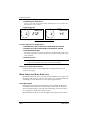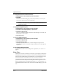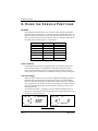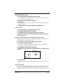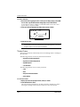
1
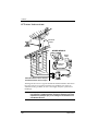
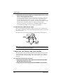
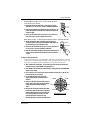
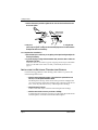
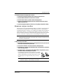
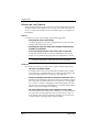
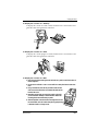
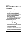
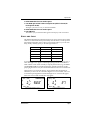
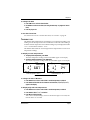
System Components
1. INTRODUCTION
The Weather Wizard III provides sophisticated monitoring and logging of
essential weather conditions such as inside and outside temperature, wind
direction, wind speed and wind chill. This instruction manual takes you stepby-step through the process of assembling, testing, and installing your Weather
Wizard III so you can begin collecting data as soon as possible.
The standard station comes with all the sensors necessary to monitor the essential weather conditions described above. For instructions on how to install and
operate optional accessories, such as the Rain Collector, please refer to the
appropriate manual.
If you have a non-standard station (e.g., Wireless or EZ-Mount), please refer to
the separate installation manual provided before continuing with this installation.
S YSTEM C OMPONENTS
Your Weather Wizard III consists of the following components. Please check to
be sure you have all of the components listed before proceeding.
Mounting Base
(attached to
bottom
of Console)
Wind Vane
Anemometer Arm
with 40 feet (12.2 meters)
of cable
Drip
Rings
Weather Station Console
Anemometer
Base
Wind Cups
AC Power
Adapter
Cable Labels
(not shown)
External Temperature Sensor
with 25 feet (7.6 meters)
of cable
Junction Box Cable
8 feet (2.4 meters) long
Weather Wizard III
Junction Box
1 1/2" U-Bolts
1/4" Flat Washers
1/4"– 20 Hex Nuts
4–40 x 1-1/8" Pan Head
Self-Threading Screw
#4 Flat Washer
#4 Lock Washer
4–40 Hex Nut
#6 x 1/2"
#6 x 1"
#8 x 3/4"
1/4" x 1-1/2" Allen
Pan Head
Pan Head
Pan Head
Self-Threading Self-Threading Self-Threading Lag Screws Wrench
Screws
Screws
Screws
Page 1
Introduction
O PTIONAL A CCESSORIES
The following accessories are designed for use with the Weather Wizard III.
• Rain Collector
Enables you to measure daily and accumulated rainfall. Separate models
measure rainfall in either 0.01 inch or 0.2 mm increments. Optional Rain
Collector Heater allows you to measure freezing rain or the moisture
content of snowfall.
• WeatherLink® Software and Data Logger
Logs data gathered by the Weather Wizard III, downloads it to your PC
or Macintosh®, and generates reports and graphical displays of your
weather data.
• Car/Boat/RV Lighter Cord
Uses the cigarette lighter in your car, RV, truck, or boat to power the
Weather Wizard III. Replaces the standard AC-power adapter.
• Sensor Mounting Arm
A single-location mounting option for all your sensors. Includes positioning for anemometer, external temperature sensor (with Radiation
Shield), and Rain Collector (with Rain Collector Shelf).
• Radiation Shield
Protects the temperature sensor from the effects of the sun’s radiated and
reflected heat. Increases the life of the sensor and the accuracy of the
readings.
• Protected Junction Box
Provides upgraded protection against radio frequency interference (RFI),
electrostatic discharges (ESD), and power surges that can come through
sensor wires. Replaces junction box included with the station.
• Extension Cables
Extends cable length for total cable runs of 80-140 feet (24-42 m) sensor
to console. Order the 4-Conductor Extension Cable [in lengths of 40 feet
(12 m) or 100 feet (30 m)] for use with the anemometer, external temperature sensor, Rain Collector, or WeatherLink.
• Junction Box Cables
Order a Standard 8-Conductor Cable for greater flexibility in the placement of your console. Comes in lengths of 25, 50, and 100 feet (7.6, 15.2,
and 30.4 m).
Page 2
Weather Wizard III
Tools and Materials Needed for Installation
T OOLS
AND
M ATERIALS N EEDED
FOR I NSTALLATION
In addition to the enclosed components, you will need the following tools and
materials to complete the installation. Please be sure you have everything you
need before proceeding with the installation.
• Cable clips or weather-resistant cable ties—with screw holes or other means for
mounting
• Small and medium-sized screwdrivers
• Hand-held magnetic compass or local area map
• Hammer
• Small adjustable wrench
• Duco® Cement (or similar adhesive or glue for gluing plastic). Note that we do not
recommend the use of “super glue” type products.
Optional Tools and Materials
• 9-volt alkaline battery to be used as backup power supply (page 6)
• Carpenter’s level to level the anemometer base (page 10)
• Electric drill with 3/16” (4.8 mm) and/or #29 (0.136” or 3.5 mm) drill bits to drill
pilot holes (page 10 and page 13)
• Electric tape if mounting the anemometer on metal mast or pipe (page 11)
• 2 stainless steel hose clamps if mounting the anemometer on pipe with diameter
greater than 1 1/4” (32 mm) (page 11)
• Standard switch box if mounting the console with the wires running inside the
wall (page 14)
• Medium Phillips screwdriver if mounting the console on a wall (page 15)
Weather Wizard III
Page 3
Introduction
A T YPICAL I NSTALLATION
Rain
RainCollector
Collector
(optional)
(optional)
Anemometer
Anemometer
WEATHER
WEATHER WIZARD
WIZARD III
III
AC
ACPower
Power
Adapter
Adapter
External
External
TempTemperature
erature
Sensor
Sensor
To
ToWeatherLink
WeatherLink
(optional)
(optional)
Power
Power
Outlet
Outlet
TEMP
TEMP
WEATHER
WEATHER
COMPUTER
COMPUTER
RAIN
RAIN
WIND
WIND
NORTH
NORTHSIDE
SIDEOF
OFBUILDING
BUILDINGininNorthern
NorthernHemisphere
Hemisphere
SOUTH
SOUTHSIDE
SIDEOF
OFBUILDING
BUILDINGininSouthern
SouthernHemisphere
Hemisphere
Junction
JunctionBox
Box
Cable
Cable
Junction
JunctionBox
Box
The diagram above shows a typical Weather Wizard III installation. The following pages will give you specific instructions for installing your station. To
avoid unnecessary problems, be sure to thoroughly test your system before
installing it.
WARNING: Climbing on your roof can be hazardous. If you are uneasy about installing your
unit, please have a qualified professional complete the installation. Davis specifically disclaims any liability for injury or loss resulting from the installation or use
of the Weather Wizard III.
Page 4
Weather Wizard III
Powering the Weather Wizard III
2. A S S E M B L I N G T H E S T A T I O N
The Weather Wizard III is a precision instrument, designed to give extremely
accurate readings. As with any precision instrument, care must be used during
assembly. These instructions detail how to assemble the stations with a minimum of time and effort.
P OWERING
THE
W EATHER W IZARD III
The Weather Wizard III is powered by 9- to 12-volt DC (direct current). In
North America, the power adapter included with your unit converts 120-volt,
60-Hz AC (alternating current) to 9-volt DC, allowing you to run the unit on
ordinary household current. You may also run the Weather Wizard III on the
12-volt DC power supplied by a car, boat, or RV battery by using the optional
Car/Boat/RV Lighter Cord.
If you are outside North America and in a location where the power supply is
not equivalent to the North American standard (120-volt, 60-Hz), check to see if
your local dealer has supplied a power adapter that is appropriate for your
power supply before you connect the power adapter to the console. If not, you
must use a power converter/transformer or the appropriate power adapter (9volt, 2.5-mm female plug).
In any case, we recommend that you also install a 9-volt alkaline battery as a
backup power supply. In the event of a power outage, the battery will power
the station. Not only will this prevent the loss of stored data in the console, but
will also allow you to continue observing weather conditions during the power
outage.
New alkaline batteries will power the Weather Wizard III for 24 - 48 hours. For
maximum security, keep the battery backup fresh. You should replace batteries
any time the unit has operated on battery power for more than 18 hours. To
prevent loss of data when replacing batteries, make sure the unit is receiving
power from the adapter before changing batteries.
Note: We do not recommend the use of Ni-Cad batteries. Ni-Cad batteries carry less power than alkaline
batteries, and they will not be recharged by the station. In the event of a power outage, Ni-Cad batteries will be able to power the station for a shorter period of time than alkaline batteries will.
To Connect the Power Adapter to the Console
1. Remove the mounting base from the console.
Push down on the large tab behind the display until it will easily slide out from
the notch. Then lift the mounting base so the two smaller tabs behind the keyboard slide free. Place the mounting base aside until you mount the console (see
“Displaying the Console” on page 14).
2. Slide the power adapter plug into the jack marked POWER underneath the console.
Weather Wizard III
Page 5
Assembling the Station
3. Plug the other end of the power adapter into an appropriate power outlet or, preferably, into a computer-grade surge protector.
It is highly recommended that you plug the power adapter into a computer-grade surge
protector, especially in lightning-prone areas. Once power is applied, the console
should run through a brief self-test procedure. All of the display segments
appear, and the console beeps twice within 10 seconds (3 times within 20 seconds
if WeatherLink is installed) to indicate everything is working properly.
After the second beep (or the third beep with WeatherLink), the compass
rose and the time (reading 12:00 a.m.) appear on the display.
To Install the Battery Backup Power Supply
Before you install the backup battery, make sure AC power is connected and
the console is completely powered up. Installing the battery first can cause the
console to lock up.
Once the console is powered up, install the backup battery as shown below.
Underside
of Console
Battery
Cover
Release
Tab
Standard
9-Volt Alkaline
Battery
Note: When the unit is operating on battery power, the digits on the right side of the display blink on and
off. The unit operates normally in all other respects.
C ONNECTING
THE
C ONSOLE
AND J UNCTION
B OX
The junction box is the connecting point between the external sensors and the
console. Information from the sensors comes into the junction box. The junction box then relays that information to the console where it is processed and
displayed.
To Connect the Console and Junction Box
1. Plug one end of the 8-foot (2.4-meter) long junction box cable into the jack labeled
JUNCTION BOX underneath the console.
2. Plug the other end of the cable into the jack marked CONSOLE on the junction box.
Page 6
Weather Wizard III
Assembling the Anemometer
A SSEMBLING
THE
A NEMOMETER
To assemble the anemometer you will need the following: anemometer arm
(with cable), anemometer base, wind cups, drip rings, allen wrench, 4-40 x
1 1/8-inch pan head screw, #4 flat washer, #4 lock washer, and 4-40 hex nut.
Avoid lubricating the wind cup shaft and bearings or the wind vane shaft. Natural or synthetic lubricant affects the normal operation of the anemometer by
reducing the component's efficiency. It also may attract insects which can jam
moving parts.
Note: Do NOT attach the wind vane at this time. Wait until you have installed the anemometer (see
page 11) before attaching wind vane.
To Attach the Anemometer Arm to the Anemometer Base
1. Insert the anemometer arm into the anemometer base, sliding cable through the slot
in the base as shown. Line up the small hole in the arm with the holes in the base.
2. Insert the 4-40 screw into one of the holes in the base and through the arm.
The screw should slide easily through the holes.
3. Secure as shown below.
4-40 Hex Nut
#4 Lock Washer
#4 Flat Washer
4-40 x 1" Pan Head Screw
To Attach the Drip Rings to the Wind Vane and Anemometer Arm
The drip rings provide excellent protection against icing of the wind vane and
wind cups. If you choose not to install them, however, the anemometer will
function normally in non-icy conditions.
1. Apply adhesive liberally to the inside of one of the drip rings and install on the wind
vane as shown below.
Make sure the lower edge of the drip ring is approximately parallel to the bottom
of the wind vane.
Wind Vane
A
B
Duco Cement
Drip Ring
C
Drip Ring
Lower edge of inside ring
(approximately parallel
to bottom of wind vane)
Weather Wizard III
Page 7
Assembling the Station
2. Apply adhesive liberally to the inside of the other drip ring and install on the WIND
CUP END OF THE ANEMOMETER CONTROL HEAD as shown below.
The wind cup end of the control head is the smaller of the two stainless steel
shafts.
Note: When attaching drip ring, make sure the lower edge of the ring is aligned with the lower edge of
the control head. If the drip ring extends below the lower edge of the control head, the wind cups
will not have room to slide on.
Control Head
Lower edge of outside ring
(aligned with lower
edge of control head)
Smaller Shaft
3. After the cement has properly cured (according to the cement’s direction), follow the
instructions below to attach the wind vane and wind cups to the anemometer.
To Attach the Wind Cups to the Anemometer Arm
1. Push the wind cups onto the smaller of the two stainless steel shafts at the end of the
arm.
2. Slide the wind cups as far up the shaft as possible.
3. Use the allen wrench provided to tighten the set screw on the side of the wind cups.
Note that when you let go of the wind cups, they should drop slightly.
4. Spin the wind cups. If they do not spin freely, loosen the set screw and lower the cups
slightly. Repeat until the wind cups spin freely.
Push cups onto
stainless steel
shaft
Page 8
Tighten set screw
with allen wrench
Weather Wizard III
Testing the Anemometer
3. TESTING THE STATION
Before continuing with the installation, test the station in your living room or
workshop. If you have purchased the optional rain collector or additional sensors, now is the time to assemble and test these using the appropriate manual.
Consult the Troubleshooting Guide on page 32, or the guides in the respective
manuals, if you experience any difficulty.
Note: You should test each external sensor without extension cables first, and then repeat the test with
extension cables. In this way, you can be reasonably sure whether any problems are the fault of the
extension cables or the external sensor itself.
T ESTING
THE
A NEMOMETER
Before you install the anemometer, make sure that the wind speed and wind
direction sensors are functioning correctly.
1. Insert the cable plug at the end of the anemometer cable into the jack marked WIND
on the junction box.
2. Test your assembly by spinning the wind cups.
You should get a speed reading other than 0 on the compass rose in the console
display. If you do not, loosen the set screw and move the wind cups slightly up
or down on the shaft until you get a reading other than 0. Once you are getting a
reading, use the allen wrench provided to tighten the set screw on the side of the
wind cups. Do not over-tighten.
3. Turn the wind direction shaft (the larger of the two stainless steel shafts on the control head) with your fingers.
Check that the direction readings change on the compass rose in the console display.
T ESTING
THE
E XTERNAL T EMPERATURE S ENSOR
Using the steps below, check to see that you get a reading from the external
temperature sensor as well.
To Test the Temperature Sensor
1. Insert the cable plug at the end of the external temperature sensor into the jack
marked TEMP on the junction box.
2. Press TEMP on the console.
A temperature reading and the words INSIDE and TEMPERATURE should
appear on the display.
3. Press TEMP again.
A temperature reading and the words OUTSIDE and TEMPERATURE should
appear on the display.
Weather Wizard III
Page 9
Installing the Station
4. INSTALLING THE STATION
Make sure you have thoroughly tested the station before installing it. Then,
decide where you will place each component—the junction box, the console,
and all external sensors. Pay close attention to the suggestions given in the sections dealing with the individual components, as well as the following general
suggestions:
• The junction box cable must be able to reach the console.
If you want to place the junction box and console more than 8 feet (2.4 m)
apart, you will need a longer junction box cable (see page 2).
• The cable coming from each external sensor must be long enough to reach the
junction box.
To prevent wind damage, leave some slack to allow the cables to be
secured to available surfaces. If the sensors are placed farther away than
their allotted cable lengths allow, use extension cables (see page 2).
I NSTALLING
THE
A NEMOMETER
Most people install the anemometer on the roofs of their houses, where wind
flow is unobstructed by trees and nearby buildings. For the most representative readings, the anemometer should be mounted at least 4 feet (1.2 m) above
the roof line. You can do this by mounting the anemometer on your television
antenna or on a raised piece of wood or metal pipe.
We have included the hardware most commonly needed for the installation of
the anemometer. The hardware you use depends upon where you install your
unit. You may need to adapt or purchase additional hardware to fit your individual requirements.
To Install the Anemometer
1. Disconnect the anemometer cable from the junction box.
2. Wrap the WIND cable labels around each end of the cable.
3. Mount the anemometer according to the following instructions. As you do so, use a
carpenter's level to make sure the anemometer base is mounted vertically.
W OODEN P OST OR S URFACE
1. Locate a suitable mounting surface for the anemometer
base. The mounting surface should be at least as wide as
the anemometer base and level.
2. Hold the anemometer base against the wood surface
and use a pencil to mark the location of the four holes
on the base.
3. Use an electric drill with a 3/16 inch (4.8-mm) drill bit to
make pilot holes in these locations.
4. Drive the four lag screws through the holes in the anemometer base and into the wood.
Page 10
Weather Wizard III
Installing the Anemometer
A NTENNA M AST OR M ETAL P IPE - OUTSIDE DIAMETER 3/4 TO
1 1/4 INCHES (19 TO 32 MM )
1. Make sure that the antenna mast or metal pipe is properly
grounded. If you are not sure, consult a qualified professional.
2. Hold the anemometer base against the pipe and insert the two
U-bolts through the back of the base so that the U-bolts wrap
around the pipe.
3. Place a 1/4-inch washer and a 1/4-20 hex nut over each end of
the U-bolts. Use a wrench to tighten the hex nuts.
M ETAL M AST OR P IPE - OUTSIDE DIAMETER GREATER THAN 1 1/4 INCHES (32 MM )
1. Obtain two stainless steel hose clamps large enough to fit
around the mast or pipe and the anemometer base. These can
be purchased at your local hardware store.
Metal Pipe
Hose Clamps
2. Make sure that the metal mast or pipe is properly grounded. If
you are not sure, consult a qualified professional.
3. Hold the anemometer base against the pipe and fasten the hose
clamps over the anemometer base and around the metal mast
or pipe.
To Attach the Wind Vane
To mount the wind vane, you will need to look at the console display. You may
wish to have a friend or family member on the ground do this for you. Or, you
may wish to bring the console and junction box onto the roof with you.
1. After installing the anemometer, re-insert the plug at the end of the anemometer
cable into the jack marked WIND on the junction box
2. Press WIND on the console until a wind direction reading and the word DIRECTION
appear on the display.
3. Use a compass or local area map to determine which direction (N, S, E, W, NE, etc.)
the anemometer arm is pointing.
4. Use the wind direction chart to find the
degree reading which corresponds to that
direction.
5. Slowly turn the wind direction shaft with your
fingers. Stop turning when the console display
reaches the degree reading obtained in
step 4.
0° N
315° NW
270° W
6. Being careful to keep the stainless steel shaft
from turning, place the wind vane on the shaft
with the bullet-shaped nose of the vane pointing in the same direction as the arm. Leave
approximately a 1/16-inch (1.5-mm) gap
between the base of the wind vane and the arm.
Weather Wizard III
45° NE
90° E
225° SW
135° SE
180° S
WIND DIRECTION CHART
Page 11
Installing the Station
7. Use the allen wrench provided to tighten the set screw on the side of the wind vane.
Do not over-tighten.
Push the
wind vane
onto the
stainless steel
shaft
Tighten set screw
with allen wrench
8. Test your assembly by pointing the wind vane in any direction and—using the compass or map as a guide—making sure the console displays the correct wind direction.
Re-adjust the wind vane if necessary.
To Complete the Installation
1. Spin the wind cups to make sure you are getting a wind speed reading. Re-adjust the
wind cups if necessary.
2. To prevent fraying or cutting of the anemometer cable, secure the cable so it does not
whip about in the wind.
Secure the cable to a metal mast or pipe by wrapping electrical tape around them
both. Leave the bulk of the cable loose until you install the junction box on
page 13.
I NSTALLING
THE
E XTERNAL T EMPERATURE S ENSOR
Use the following guidelines when deciding where and how to position the
external temperature sensor:
• Place the external temperature sensor in a location that is protected from sun
and rain, or use the optional Radiation Shield.
The black plastic end cap on the sensor heats up in direct sunlight. This
can cause erroneous temperature readings and/or damage to the sensor.
Also, water may affect the accuracy of the temperature readings.
• Suspend the sensor in the air.
Contact with other objects could cause false temperature readings.
• Place the sensor under an eave on your house or building.
To shield the sensor from the sun, place it on the north side in the Northern Hemisphere, south side in the Southern Hemisphere.
Page 12
Weather Wizard III
Mounting the Junction Box
To Install the External Temperature Sensor
1. Disconnect the external temperature sensor cable from the junction box.
2. Wrap the TEMP cable labels around each end of the cable.
3. Place the sensor wherever you wish to measure the temperature.
4. Plug the end of the external temperature sensor cable back into the jack marked
TEMP on the junction box.
5. Check the temperature display to make sure you are getting a temperature reading.
M OUNTING
THE J UNCTION
B OX
The junction box may be installed either indoors or outdoors. The junction box
is not resistant to moisture, dirt, or other outdoor stresses so, if you plan to
install the junction box outdoors, use a weather-proof shelter such as the Davis
Multi-Purpose Shelter or Complete System Shelter. If indoors, place the junction box well above the floor so moisture from mopping, impact from vacuum
cleaners, or dirt from sweeping will not cause damage to the junction box.
Note: Before mounting the junction box, make sure that each sensor cable—WIND, RAIN, or TEMP—is
labelled on either end so as to alleviate confusion both during the installation and whenever you need
to disconnect a sensor/component.
To Mount the Junction Box
1. Hold the junction box against the wall (or mounting surface) and use a pencil to mark
the location of the holes on the junction box.
2. Use an electric drill with a #36 (2.5-mm) drill bit to make pilot holes.
3. Drive the two #6 x 1/2-inch screws through the holes on the junction box and into the
wall (or mounting surface).
4. To prevent fraying or cutting of the all the cables leading to the junction box, secure
the cables so they do not whip about in the wind.
Use cable clips or weather resistant cable ties to secure the
cable underneath the eaves of your house or in a location
similarly shielded from rain. Make sure the cable is secure
by placing clips or ties approximately every 3-5 feet (11.6 m).
Cable Clip
Cable Tie
Note: Do not use metal staples or a staple gun to secure the cable. Metal staples—especially when
installed with a staple gun—have a tendency to cut the cables.
Weather Wizard III
Page 13
Installing the Station
D ISPLAYING
THE
C ONSOLE
Most people position the console indoors in a location where the keyboard is
readily accessible and the display is easy to read. Some install the console outdoors in a weather-proof shelter (such as the Multi-Purpose or Complete System Shelter).
Indoors
For the most accurate indoor readings, follow these suggestions:
• Avoid placing the console in direct sunlight.
The black casing heats up in direct sunlight. This can cause erroneous
readings and/or damage to the unit.
• Avoid placing the console near radiant heaters, heating/air conditioning ducts,
humidifiers, or de-humidifiers.
• If you are mounting the console on a wall, choose an inner or interior wall.
Avoid walls which heat up or cool down depending on the weather,
unless you are specifically targeting that wall’s temperature variation.
Note: To display the console with the junction box cable running inside the wall, attach the mounting base to an empty switch box, using the two screw holes on the mounting base.
Outdoors
If you prefer to mount your console outdoors, please consider the following:
• The console is not weather-resistant.
If installed outdoors, the console should be mounted inside a weatherproof shelter (e.g., the Multi-Purpose or Complete System Shelter). The
console will operate between -5˚ and 140˚ F (-20˚ and 60˚ C).
• The liquid crystal display freezes when the temperature drops below 32˚F (0˚C).
Whether or not the display is functioning, the console continues logging
data and is able to download the data to a computer for viewing when
it’s as cold as -5˚F (-20˚C). The display resumes functioning as the temperature rises. You can use a Multi-Purpose or Complete System Shelter
Heater to prevent the display from freezing.
• The console’s temperature sensors may be unreliable in an outdoor shelter.
If you mount the console outdoors (in a shelter), it is recommended that
you rely on the external temperature sensor for the most accurate outdoor readings. The console’s temperature readings are necessarily less
accurate because of the trapped air within the shelter.
Page 14
Weather Wizard III
Displaying the Console
To Display the Console on a Tabletop
To display the console on a table or desk, attach the base as shown below and
guide the cables through the slots indicated.
To Display the Console on a Shelf
To display the console upright on a shelf, attach the base as shown below and
guide the cables through the slots indicated.
To Display the Console on a Wall
1. Hold the mounting base flat against the wall and use a pencil to mark the location of
the two keyholes.
2. Use an electric drill with a #36 or 2.5-mm drill bit to make pilot holes in these locations.
3. Using a screwdriver, drive the two pan head screws into the
wall. Leave at least 1/8 inch (3 mm) between the wall and the
heads of the screw.
4. Depending on how high you mount the console on the wall,
you can use either tabletop or shelf orientation. Attach the
mounting base in the orientation you prefer.
5. Slide the keyholes on the back of the mounting base over the
two screw heads. Lock the console into place by gently sliding
it downward until it no longer moves.
Weather Wizard III
Page 15
Using the Weather Functions
5. USING THE WEATHER FUNCTIONS
U SING
THE
E NTER K EY
The ENTER key is used to enter or change data. You should become familiar
with the use of this key, since it serves many purposes in operating the Weather
Wizard III.
To Change Data Using the Enter Key
1. Press ENTER and hold it down.
The first digit on the left will flash and then begin to cycle through all the possible entries for the function you are changing.
2. When the display reaches the entry you want, release the ENTER key.
3. Press ENTER again and hold it down.
The second digit from the left will flash and then begin to cycle through all the
possible entries for the function you are changing.
4. When the display reaches the entry you want, release the ENTER key.
5. Repeat this process for the remaining digits.
It makes no difference which digit you change first. If you enter a digit incorrectly, accidentally skip past a digit, or only want to change certain digits, simply
press and release ENTER until the desired digit is flashing.
6. Press any key or wait four seconds without pressing ENTER to save the entry.
Example of Using the Enter Key - Setting the Time
1. Press TIME until the time setting appears on the display.
N
NW
NE
AM
W
E
MPH
SW
SE
BAROMETRIC
TREND
S
TIME DISPLAY
2. Press UNITS to change from the 12-hour format to the 24-hour format, as desired.
The 12-hour format is indicated by the symbol AM or PM. The 24-hour format is
indicated by the symbol 24HR.
3. Change the hour by pressing and holding down ENTER.
If you are using the 12-hour format, the digits representing the hour (the first two
digits on the left) cycle from 12 AM to 11 PM as you hold down ENTER. If you
are using the 24-hour format, the digits representing the hour cycle from 0 to 23
as you hold down ENTER.
4. Release ENTER when the current hour appears.
5. Press ENTER again and hold it down to change the tens position in minutes (the third
digit from the left).
The digits cycle from 0 to 5 as you hold down ENTER.
Page 16
Weather Wizard III
Highs and Lows
6. Release ENTER when the correct number appears.
7. Press ENTER again and hold it down to change the ones position in minutes (the
fourth digit from the left).
The digits cycle from 0 to 9 as you hold down ENTER.
8. Release ENTER when the correct number appears.
9. Press TIME twice.
The number you just entered should appear in the display as the current time.
H IGHS
L OWS
AND
The Weather Wizard III records highs and lows for many of its functions. Highs
and lows are maintained until you manually clear the entries, or until power is
interrupted. Depending on how often you clear highs and lows you can track
daily, weekly, monthly, yearly, or all-time highs and lows.
RECORDED HIGH
RECORDED LOW
Inside Temperature
√
√
Outside Temperature
√
√
Wind Speed
√
X
Wind Direction
X
X
Wind Chill
X
√
In general, highs and lows are displayed by pressing RECL (RECALL) once or
twice. The high or low appears in the display along with the word HIGH or
LOW and the words which normally accompany the function (e.g., OUTSIDE
and TEMPERATURE for outside temperature). Specific instructions for displaying highs and lows may be found within the instructions for each function.
Highs and lows are stored in memory along with the time and the date at
which they occurred. To see what time a high or low was recorded, wait a few
seconds after pressing RECL. The time the high or low occurred will appear.
Wait a few more seconds and the date will appear.
N
HIGH
NW
N
OUTSIDE
TEMPERATURE
NE
HIGH
NW
NE
F
W
E
W
E
MPH
MPH
SW
SE
SW
S
SE
S
High Outside Temperature: 92.3˚F
SPEED
High Wind Speed: 27 mph
TYPICAL HIGH AND LOW DISPLAYS
Weather Wizard III
Page 17
Using the Weather Functions
T IME
AND
D ATE
The Weather Wizard III can display time in either a 12-hour or a 24-hour format. In the 12-hour format, either an AM or a PM is displayed with the time. In
the 24-hour format, the symbol 24HR is displayed with the time. In either case
the hour is on the left, separated from the minutes by a colon.
The date is displayed with the month on the left, separated from the day by
three vertical dots. The symbol MO:DAY appears.
To Display the Current Time and Date
1. To display the time, press TIME.
The time and symbol AM (or PM or 24 HR) appear on the display.
2. To display the date, press TIME again.
The date and the symbol MO:DAY appear on the display.
N
N
NW
NE
NW
NE
AM
W
E
W
E
MPH
SW
MPH
SE
SW
S
SE
S
Time: 9:27 a.m.
MO:DAY
Date: April 19
TIME AND DATE DISPLAYS
To Change the Time Format
1. Press TIME once or twice to select the time.
2. Press UNITS.
The console switches from the 12-hour to the 24-hour format (or vice versa) and
the symbol changes from AM or PM to 24 HR (or vice versa). To return to the
original format, press UNITS again.
N
NW
NE
24HR
W
E
MPH
SW
SE
S
24-HOUR TIME DISPLAY
To Change the Time
1. Press TIME once or twice to select the time.
2. Press UNITS to select the 12-or24-hour format, as desired.
3. Use ENTER to set the correct time (see “Using the Enter Key” on page 16 for instructions).
4. Press any key to exit.
Page 18
Weather Wizard III
Temperature
To Change the Date
1. Press TIME once or twice to select the date.
2. Use ENTER to set the correct date (see “Using the Enter Key” on page 16 for instructions).
3. Press any key to exit.
To Use the Time Alarm
For instructions on how to use the time alarm, see “Alarms” on page 24.
T EMPERATURE
The Weather Wizard III measures and displays two temperature readings. One
reading is from the temperature sensor inside the console. The other reading is
from the external temperature sensor. Both readings may be displayed in either
˚F or ˚C in increments of either 1˚ or 0.1˚.
The Weather Wizard III also records high and low temperatures for each set of
temperature readings.
To Display Current Temperatures
1. To display inside temperature, press TEMP.
The inside temperature reading and the word INSIDE appear on the display.
2. To display outside temperature, press TEMP again.
The outside temperature reading and the word OUTSIDE appear on the display.
N
N
OUTSIDE
NW
TEMPERATURE
NE
NW
INSIDE
NE
TEMPERATURE
F
W
E
C
W
E
MPH
SW
MPH
SE
SW
S
SE
S
Outside Temperature: 68.7˚F
Inside Temperature: 24˚C
INSIDE AND OUTSIDE TEMPERATURE DISPLAYS
To Change the Unit of Measure
1. Press TEMP once or twice to select inside or outside temperature, as desired.
2. Press UNITS until the desired unit of measure and resolution (1˚F, 0.1˚F, 1˚C, 0.1˚C)
appear in the display.
To Display High and Low Temperatures
1. Press TEMP once or twice to select inside or outside temperature, as desired.
2. Press UNITS to select ˚F or ˚C as desired.
3. Press RECL to display the high.
After a few seconds, the display will show the time the high was recorded, and
then the date it was recorded.
Weather Wizard III
Page 19
Using the Weather Functions
4. Press RECL again to display the low.
After a few seconds, the display will show the time the low was recorded, and
then the date it was recorded.
5. Press any key to exit.
N
NW
HIGH
INSIDE
NE
N
TEMPERATURE
LOW OUTSIDE
NW
TEMPERATURE
NE
C
W
E
F
W
E
MPH
SW
MPH
SE
SW
S
SE
S
High Inside Temperature: 27.2˚C
Low Outside Temperature: 44˚F
HIGH AND LOW TEMPERATURE DISPLAYS
To Clear High and Low Temperatures
1. Press TEMP once or twice to select inside or outside temperature, as desired.
2. Press RECL once or twice to select the high or low temperature, as desired.
3. Press CLEAR and hold it down.
The display will flash several times, and then the old reading will be replaced by
the current temperature. As the temperature rises and falls, the high and/or low
will be updated.
4. Press any key to exit.
Note: High and low temperatures are independent of each other. Clearing the high temperature does
not clear the low temperature, and vice versa. You must clear each individually.
High and Low Temperature Alarms
For instructions on how to use the high and low temperature alarms, see
“Alarms” on page 24.
W IND S PEED
AND
W IND D IRECTION
The Weather Wizard III shows wind speed and wind direction in two places on
the display. They are always shown on the compass rose on the left hand side
of the display and can be selected to show on the right hand side.
About Wind Speed
Wind speed can be displayed in either miles per hour (MPH), kilometers per
hour (KPH), nautical miles per hour (KNOTS), or meters per second (M/S).
The wind speed readings on the right side of the display and in the compass
rose will always be in the same unit of measure.
The Weather Wizard III also records the highest wind speed at your location.
Page 20
Weather Wizard III
Wind Speed and Wind Direction
About Wind Direction
The compass rose is divided into 16 points, each corresponding to a different compass point 22.5˚ apart. Wind
direction is indicated by a flashing arrow at one of these
points. The right side of the display expresses wind
direction in degree readings.
N
NW
NE
M/S
W
E
The right side of the display can be set to display Wind
SW
SE
Direction in either high (1˚ increments) or low (10˚
increments) resolution. Low resolution is probably the
S
most practical setting since even a relatively steady
COMPASS ROSE
wind has turbulence and rapidly changing speeds. Low
resolution gives you a general indication of wind direction—whether the wind
is blowing from a northerly or northeasterly direction, for example.
Under certain circumstances, however, the change in wind direction is as
important as the direction itself. Under these circumstances, the Weather Wizard III should be set to display in 1˚ increments. This change can be significant
if, for example, you are trimming the sails of your sailboat.
To Display Current Wind Speed and Wind Direction
1. To display wind speed, press WIND.
The current wind speed and the word SPEED appear on the display.
2. To display wind direction, press WIND again.
The current wind direction and the word DIRECTION appear on the display.
N
N
NW
NW
NE
W
E
NE
W
E
MPH
SW
MPH
SE
S
SW
DIRECTION
SE
S
Wind Direction: 135˚ (SE)
SPEED
Wind Speed: 15 mph
WIND DIRECTION AND WIND SPEED DISPLAYS
To Change the Unit of Measure for Wind Speed
1. Press WIND once or twice as necessary to select wind speed.
2. Press UNITS until the desired unit of measure (MPH, KPH, KNOTS, M/S) appears in the
compass rose.
Weather Wizard III
Page 21
Using the Weather Functions
To Change the Resolution for Wind Direction
1. Press WIND once or twice as necessary to select wind direction.
2. Press UNITS.
The console switches from high (1˚) to low (10˚) resolution (or vice versa). To
return to the original format, press UNITS again.
Note: When you change resolution, the word HIGH or LOW appears in the display so you know what
resolution you have changed to. Once you have selected a resolution, the word HIGH or LOW
disappears from the display.
To Display the High Wind Speed
1. Press WIND once or twice as necessary to select wind speed.
2. Press UNITS to select MPH, KPH, KNOTS, or M/S as desired.
3. Press RECL to display the high.
After a few seconds, the display will show the time the high was recorded, and
then the date it was recorded.
4. Press any key to exit.
To Clear the High Wind Speed
1. Press WIND once or twice as necessary to select wind speed.
2. Press RECL to display the high.
3. Press CLEAR and hold it down.
The display will flash several times, and then the high wind speed will be
replaced by the current wind speed. As higher wind speeds occur, the high will
be updated.
To Use the High Wind Speed Alarm
For instructions on how to use the high wind speed alarm, see “Alarms” on
page 24.
W IND C HILL
Wind chill is a measure of the effect of wind on our perception of temperature.
Through a process known as advection, wind cools off your body by transferring heat more quickly into the surrounding air. As a result, when the wind is
blowing, you perceive the temperature to be cooler than it actually is.
The Weather Wizard III automatically calculates wind chill using the wind
speed and the outside temperature readings. Wind chill is expressed as a temperature reading, which can be displayed in either ˚F or ˚C in increments of 1˚.
The Weather Wizard III also records the lowest wind chill reading at your location.
Page 22
Weather Wizard III
Rainfall
To Display the Current Wind Chill
Press WIND CHILL. The current wind chill and the words WIND CHILL
appear on the display.
N
N
NW
NW
NE
NE
C
F
W
W
E
E
MPH
MPH
SW
WIND CHILL
SE
SW
SE
WIND CHILL
S
S
Wind Chill: 45˚F
Wind Chill: -18˚C
WIND CHILL DISPLAYS
To Change the Unit of Measure
1. Press WIND CHILL.
2. Press UNITS.
The console switches from ˚F to ˚C (or vice versa) and the symbol in the display
changes from F to C (or vice versa). To return to the original format, press UNITS
again.
To Display the Low Wind Chill
1. Press WIND CHILL.
2. Press UNITS to select ˚F or ˚C as desired.
3. Press RECL to display the low.
After a few seconds, the display will show the time the low was recorded, and
then the date it was recorded.
4. Press any key to exit.
To Clear the Low Wind Chill
1. Press WIND CHILL.
2. Press RECL.
3. Press CLEAR and hold it down.
The display will flash several times, and then the low wind chill will be replaced
by the current wind chill. As the wind chill falls, the low will be updated.
4. Press any key to exit.
To Use the Low Wind Chill Alarm
For instructions on how to use the low wind chill alarm, see “Alarms” on
page 24.
R AINFALL
Before you can use the rainfall function on your Weather Wizard III, you must
first set up and install the optional Rain Collector. See the booklet included
with the Rain Collector for instructions on its use.
Weather Wizard III
Page 23
Using the Console Functions
6. USING THE CONSOLE FUNCTIONS
A LARMS
The Weather Wizard III features a set of alarms which can be programmed to
sound whenever a reading passes a particular point. Check the chart below to
determine which functions have alarms and what kind of alarms they have. All
alarms (except time) behave in basically the same way. The general procedure
for displaying and setting alarms is covered below.
HIGH ALARM
LOW ALARM
Time
*
*
Inside Temperature
√
√
Outside Temperature
√
√
Wind Speed
√
X
Wind Direction
X
X
Wind Chill
X
√
* The time alarm is a standard time alarm, just like the one on any alarm clock.
Alarm Conditions
On all high alarms, the alarm is triggered when a reading reaches the alarm
point and will continue to sound until the reading drops below the alarm
point. On all low alarms, the alarm is triggered when a reading reaches the
alarm point and will continue to sound until the reading rises above that point.
The Alarm Display
When the alarm sounds, the console makes a high-pitched beeping sound and
immediately displays the function triggering the alarm. The word ALARM
flashes on and off in the display. The alarm will continue until alarm conditions
are no longer met or the alarm is cleared. You can briefly look at other functions
by pressing the appropriate key(s), but the display will always return to the
alarming function.
If more than one alarm is sounding at once, the Weather Wizard III will scan
through all of the triggered alarms, displaying each for approximately four seconds before moving to the next.
N
N
LOW OUTSIDE
NW
NE
ALARM
TEMPERATURE
LOW
NW
NE
ALARM
C
F
W
E
W
E
MPH
MPH
SW
SE
S
SW
SE
WIND CHILL
S
Low Outside Temp Alarm: 32.0˚F
Low Wind Chill Alarm: 0˚C
TYPICAL ALARM DISPLAYS
Page 24
Weather Wizard III
Alarms
To Display an Alarm Setting
1. Press the appropriate key to display the function you desire.
For temperature you must choose between the inside and outside readings, as
each set of alarms is handled separately.
2. Press UNITS to select the desired unit of measure.
3. Press ALARM.
If you are displaying temperature, which has two alarm settings, the high alarm
setting appears first.
4. To display the low alarm setting for temperature, press ALARM again.
To Set an Alarm
1. Press the appropriate key to display the function you desire.
2. Press UNITS to select the desired unit of measure.
3. Press ALARM until the alarm setting you desire appears on the display.
4. Use ENTER to set the alarm (see “Using the Enter Key” on page 16 for instructions).
5. Press any key to exit.
Example of Setting an Alarm—Low Outside Temperature Alarm
Suppose you wanted to set the Weather Wizard III alarm to sound when the
outside temperature dropped below 40˚F.
1. Press TEMP once or twice until outside temperature is displayed.
2. If necessary, press UNITS to change to ˚F.
Using the 1˚F resolution is probably easiest, though you can set the alarm to 1˚ or
0.1˚ resolution for either Fahrenheit or Celsius.
3. Press ALARM twice to display the low alarm setting.
4. Use ENTER to set the alarm to 40˚F (see “Using the Enter Key” on page 16 for instructions).
N
LOW OUTSIDE
NW
NE
ALARM
TEMPERATURE
F
W
E
MPH
SW
SE
S
LOW OUTSIDE TEMPERATURE ALARM (EXAMPLE)
5. Press TEMP to exit.
The alarm is now set and will sound when the outside temperature drops below
40˚F.
To Silence an Alarm
Press CLEAR. The high pitched beeping sound stops, though the alarm is not
cleared. The word ALARM and the function triggering the alarm remains on
the display until alarm conditions are no longer met or the alarm is cleared.
Weather Wizard III
Page 25
Using the Console Functions
To Clear an Alarm
1. Since the function triggering the alarm is already on the display, simply press ALARM
once or twice to get the desired alarm setting (high or low) for that function.
If more than one alarm is sounding, wait until the function you want to clear
appears before you press ALARM.
2. Press and hold down CLEAR until the display shows a series of dashes.
N
LOW
NW
NE
W
ALARM
E
MPH
SW
SE
WINDCHILL
S
CLEARING AN ALARM
3. Press any key to exit.
Note: Each alarm setting is independent of every other. For instance, clearing the high inside temperature alarm does not clear the low inside temperature, high outside temperature, or low outside
temperature alarms. You must clear each alarm individually.
T OTAL C LEAR
The total clear function automatically clears all of the high and low readings at
the same time.
The following functions are reset by the total clear function:
• High and Low Inside Temperatures
• High and Low Outside Temperatures
• High Wind Speed
• Low Wind Chill
The following functions are not reset by total clear:
• Time
• Date
• Daily and Accumulated Rainfall
• Alarm Settings
To Use Total Clear
1. Display any function except highs and lows, alarms, or rainfall.
2. Press CLEAR and hold it down.
The unit will beep and the display will flash seven times and then stop. When
this happens, the high and low functions listed above have been cleared.
Page 26
Weather Wizard III
Auto Scan
A UTO S CAN
The Weather Wizard III can be set to perform an automatic scan of the weather
functions. Each reading appears on the display (in the unit of measure you last
used) for approximately four seconds before being replaced by the next function in the scan routine. There is a pre-programmed scan routine which reviews
weather functions in the order given below.
• Current, High, and Low Inside Temperature
• Current, High, and Low Outside Temperature
• Current and High Wind Speed
• Current Wind Direction
• Current and Low Wind Chill
• Daily and Accumulated Rainfall
You may also program a customized scan routine to review only the functions
you desire. The console can store one customized scan routine in addition to
the pre-programmed scan.
Note: You can enter time and/or date into the customized scan routine, though they are not included in the
pre-programmed scan routine.
To Start and Stop a Scan Routine
1. Press SCAN to begin the pre-programmed routine.
2. To begin the customized scan routine (if you have entered one), press SCAN again.
3. To stop the scan routine, press any key except SCAN or ENTER.
To Program a Customized Scan Routine
1. Press SCAN.
2. Press ENTER.
The compass rose disappears and the word SCAN appears. After a few seconds,
the display will begin to alternate between the word SCAN and the normal display to let you know you are in scan entry mode.
OUTSIDE
TEMPERATURE
SCAN ENTRY MODE
3. Press the appropriate keys to display the first function you wish to scan.
For example, press TEMP twice and RECL once for High Outside Temperature.
4. If desired, press UNITS to change the unit of measure.
Weather Wizard III
Page 27
Using the Console Functions
5. Press ENTER to store that function in the scan routine.
6. Repeat steps 3,4, and 5 until you have entered all of the functions you wish to scan.
7. When you have entered all the desired functions, press SCAN.
The customized scan routine will begin. Note that the functions you enter will be
displayed in the same order they appear during the pre-programmed scan routine, not in the order you entered them.
To Clear a Customized Scan Routine
Press SCAN, then ENTER, then SCAN again.
To Change the Customized Scan Routine
To change a scan routine, follow the instructions above (in “To Program a Customized Scan Routine”) to enter a whole new customized scan routine. You
cannot add or delete a function to an existing scan routine; you must re-enter
the scan routine in its entirety.
To Change the Unit of Measure Within the Scan Routine
Change the unit of measure as described in the individual section for the
desired function. Any changes made to the unit of measure outside of the scan
routine are reflected inside the scan routine.
Page 28
Weather Wizard III
Inside and Outside Temperature
7. CALIBRATION NUMBERS
Calibration (CAL) numbers are used to turn raw data from the sensors into
meaningful readings on the display. The standard or default CAL numbers are
automatically entered by the unit when it is first powered up and whenever
power is lost and later restored.
Calibration numbers should not be changed except for certain specialized
applications. This section explains why you may wish to change CAL, the
equations used by the Weather Wizard III, and the default values for CAL
numbers. For instructions on changing CAL, see “Changing Calibration Numbers” on page 30.
Note: We do not recommend changing the preset calibration numbers unless you are using a metric rain
collector.
I NSIDE
AND
O UTSIDE T EMPERATURE
Change CAL if you wish to adjust the Weather Wizard III so that it reads the
same as another thermometer. Note that there are individual CAL numbers for
both inside and outside temperature. If you change CAL for outside temperature, the wind chill reading will also be affected.
CALIBRATED TEMPERATURE = TEMPERATURE + CAL
Default CAL = 0 (for ˚F); 0 (for ˚C).
W IND S PEED
The four units of measure provided are generally sufficient for most applications. If you change CAL for wind speed, the wind chill readings will be incorrect.
CALIBRATED WIND SPEED = REVOLUTION X (1600 / CAL)
Default CAL = 1600 (for mph); 995 (for kph); 1843 (for knots); 3578 (for m/s).
Weather Wizard III
Page 29
Calibration Numbers
R AINFALL
Each station uses a rainfall calibration number (CAL) to determine how much
water each bucket tip (i.e., pulse) represents. The default calibration number
for rainfall assumes that you use a 0.01” rain collector.
CALIBRATED RAINFALL = # OF PULSES X (1 / CAL)
Default CAL = 100 (for 0.01" rain collector).
If you have a 0.2 mm rain collector, you must change the calibration number.
First adjust the console to display rainfall in millimeters and then change CAL
to 0005. (For instructions on how to change CAL, see “Changing Calibration
Numbers” below). Be aware that the console will revert to its default calibration (i.e., inches) if it loses power.
Note: Make sure you display rainfall in the appropriate units of measure before changing CAL; otherwise
you will be setting the wrong calibration number. If, by mistake, you change CAL before switching to
the appropriate units, you can rectify the error by switching to the appropriate units and then entering the appropriate CAL (for millimeters, 0005; for inches, 0100).
Once the console is calibrated for 0.01” (default) or 0.2 mm, you can switch the
display units as often as you like; the console accurately converts rainfall
amounts regardless of the type of rain collector you use.
C HANGING C ALIBRATION N UMBERS
1. Press the appropriate key (e.g., TEMP, RAIN, etc.) to display the reading whose CAL
number you wish to change.
2. Press UNITS to display the desired unit of measure.
3. If you are changing the CAL for wind speed or temperature, press the key you pressed
in step 1 (i.e., WIND or TEMP) again so the reading you do NOT want to change
appears in the display.
For example, to change outside temperature, display inside temperature. If you
are changing the CAL for rain, skip to step 4.
4. Press the key you pressed in step 1 and hold the key down.
After a few seconds, the display will begin to alternate between the word CAL
and the reading you want to change. After a few more seconds, the current calibration number appears.
5. Use ENTER to set CAL. (See “Using the Enter Key” on page 16 for instructions.)
If you want to enter a negative CAL for temperature, first enter the number
without the negative sign. Then return to the second digit on the left and hold
down ENTER. The display cycles through the possible entries, one of which is a
negative sign.
Note: If you do not begin entering numbers within the first second after you select a digit, the display will
exit calibration mode and return to its normal display.
Page 30
Weather Wizard III
Resetting Calibration Numbers to Default
R ESETTING C ALIBRATION N UMBERS
TO
D EFAULT
1. Write down the accumulated rainfall and all alarm settings.
You will need to reenter these values later.
2. Also write down all highs, lows, and daily rainfall.
These values will be lost and cannot be restored.
3. Remove the battery, if applicable, and unplug the power adapter from the console.
All power must be removed from the unit.
4. Reattach the power adapter and insert the battery.
The unit will start up again and all CAL numbers will be reset to their default
values.
5. Reenter the accumulated rainfall and all alarm settings.
See “Using the Enter Key” on page 16 and “Alarms” on page 24 for instructions
on how to enter the data.
Weather Wizard III
Page 31
Troubleshooting Guide
8. TROUBLESHOOTING GUIDE
While the Weather Wizard III is designed to provide years of trouble-free operation, occasional problems may arise. If you are having a problem with your
unit, please check the following guide before sending the unit in for repair. You
will be able to solve many of the problems yourself. If, after checking this
guide, you are unable to solve the problem, please call the factory at 1-510-7327814 for further instructions. Please do not return your unit for repair without
prior authorization.
C ONSOLE T IPS
Display is flashing
• Unit is operating under battery power. Check to be sure the power adapter
has not come unplugged from the console or outlet.
Display is blank
• Unit is not receiving power. Check to be sure the power adapter has not
come unplugged from the console or outlet.
• If power is interrupted, battery may be installed incorrectly. Check and reinstall.
• Battery may be run down or old. Replace.
Display shows a series of dashes in place of function reading
• Sensor for function which is "dashed out" is not plugged in.
• Cable from sensor for function which is "dashed out" may have broken wire.
Check the areas where cables have been secured carefully.
• A reading has exceeded the limits indicated on the specifications table.
• For temperature, wind speed, or rainfall: calibration numbers may be causing readings to exceed display limits. Check calibration number and adjust
if necessary.
Display is sluggish or console does not work at low temperatures
• The LCD display may not work below 32˚F (0˚C). Use the external temperature sensor in low-temperature locations and keep the console in a warmer
location. See “Displaying the Console” on page 14 for more information.
Page 32
Weather Wizard III
Temperature Tips
Display "locks up"
• Insufficient power during power up or a power surge may cause the console
to lock up. If this occurs, remove all power—disconnect any battery backup
and the AC power cord. Wait for 1 minute with all of the power removed.
Then, while the battery is removed, reconnect the AC power cord and listen
for 2 beeps within 10 seconds.
Note: If you have the WeatherLink installed, listen for 3 beeps within 20 seconds and then, if all is well,
try communicating with the WeatherLink using a computer.
• Once you receive the final beep, install a fresh backup battery, if desired, and
put it back into service.
• Davis recommends plugging the console’s power adapter into a computergrade surge protector to help avoid this problem.
T EMPERATURE T IPS
Outside temperature seems too high
• Move external temperature sensor out of direct sunlight.
• Check calibration number and adjust if necessary.
Inside temperature seems too high
• Move the console out of direct sunlight.
• Make sure the console is not in contact with an exterior wall which heats up
in sunlight.
• Make sure the console is not near a heater or other internal heat source
(lamps, appliances, etc.).
• Check calibration number and adjust if necessary.
Outside temperature seems too low
• Check calibration number and adjust if necessary.
Inside temperature seems too low
• Make sure the console is not in contact with an exterior wall which cools
down when outside temperature drops.
• Make sure the console is not near an air conditioner.
• Check calibration number and adjust if necessary.
Weather Wizard III
Page 33
Troubleshooting Guide
W IND T IPS
Wind speed reading seems lower than expected
• Check installation by spinning wing cups. If you get a reading, the wind
cups are installed correctly. They should spin more freely after an initial
break-in period of one or two weeks.
Wind speed reads 0 either all the time or intermittently
• Make sure anemometer cable is plugged into jack marked WIND on junction box.
• Check for broken wire along length of anemometer cable. Carefully check
areas where the cable has been secured.
• Check installation by spinning wind cups. If you do not get a reading, try
moving the wind cups down about 1/16 inch (1.5 mm) on the shaft.
• If you still do not get a reading, the problem is probably with the anemometer. Call factory for return authorization.
Wind speed reading seems too high or too low
• Check calibration number and adjust if necessary.
Wind direction reading is dashed out
• Make sure anemometer cable is plugged into jack marked WIND on junction box.
• Check for broken wire along length of anemometer cable. Check the areas
where the cable has been secured carefully.
• If these steps do not reveal the problem, the problem is probably with the
anemometer. Call the factory for return authorization.
W IND C HILL T IPS
Wind chill reading seems too high or too low
• Check calibration number for temperature and wind speed. Adjust if necessary.
Page 34
Weather Wizard III
Wind Chill Tips
9. SPECIFICATIONS
Inside Temperature
Range: -5˚ to 140˚ F (-20˚ to 60˚ C)
Accuracy: ± 1˚F (± 0.5˚C)
Outside Temperature
Range: -50˚ to 140˚ F (-45˚ to 60˚ C)
Accuracy: ± 1˚F (± 0.5˚C)
Wind Direction
Display Resolution: 16 points (22.5˚) on compass rose, 1˚ in digital display
Accuracy: ± 7˚
Wind Speed
Range: 2 to 175 mph, 4 to 280 kph, 2 to 152 knots, 0.9 to 78 m/s
Accuracy: ± 5%
Wind Chill
Range: -134˚ to 98˚F (-92˚ to 37˚C)
Accuracy: ± 4˚F (± 2˚C)
Rainfall
Daily Range: 0 to 40.95”(0 to 819 mm)
Accumulated Range: 0 to 99.99”(0 to 9999 mm)
Accuracy: ±(4% + 1 count) for rates from 0.01” to 2” (0.2 mm to 50 mm) per hr;
±(5% + 1 count) for rates from 2” to 4” (50 mm to 100 mm) per hr
Time
Accuracy: ± 15 sec/month
Weather Wizard III
Page 35