1
AC30A
COMPRESSOR
OWNERS MANUAL
Rev. 03/15/2011
Serial No. __________________
Mailing Address:
P.O. Box 580697
Tulsa, OK 74158-0697
Physical Address:
4707 N. Mingo Rd.
Tulsa, OK 74117-5904
Manual No. AC30A
Rev. 07/08/2008
Phone (918) 836-0463
Fax (918) 834-5979
http://www.autocrane.com
Auto Crane Warranty Registration
Fax Transmission
To:
Warranty Department
Fax:
From:
Re:
(918) 834-5979
Date:
Product Registration
End User Information:
Pages:
(Required for Warranty Activation)
Name:
Phone:
Address:
City:
State:
Contact:
E-mail Address:
Distributor Information:
Zip:
(Required for Warranty Activation)
Name:
Address:
City:
State:
Contact:
E-mail Address:
Product Information:
Model No.:
Zip:
(Required for Warranty Activation)
Serial No.:
Date Product Delivered:
VIN #
Date Processed:*
* For Auto Crane use only
ONE REGISTRATION FORM PER UNIT (CRANE OR BODY)
Registration form must be mailed or faxed within 15 days of customer installation.
Mail to:
Warranty Department
Auto Crane Company
P.O. Box 581510
Tulsa, OK 74158-0697
Warranty Registration
Rev. 050905
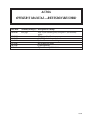
AC30A
OWNER’S MANUAL – REVISION RECORD
Rev Date
09/02/03
05/09/05
11/28/05
06/10/06
07/12/07
08/13/07
11/28/11
Section(s)OrPage(s) Description of Change
Last page
New 2-year warranty policy to replace 1-year warranty
policy
2nd Quarter New Revisions
3-1.0.0 Updated for new hydraulic motor
Updated for new machine design.
Bill of Materials Audit
Updated Drawing
Updated Drawing 200280-999
10/09
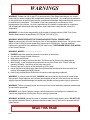
WARNINGS
WARNING! Federal law (49 cfr part 571) requires that the Final Stage Manufacturer of a vehicle
certify that the vehicle complies with all applicable federal regulations. Any modifications performed
on the vehicle prior to the final state are also considered intermediate stage manufacturing and must
be certified as to compliance. The installer of this crane and body is considered on of the
manufacturers of the vehicle. As such a manufacturer, the installer is responsible for compliance
with all applicable federal and state regulations, and is required to certify that the vehicle is in
compliance.
WARNING! It is the further responsibility of the installer to comply with the OSHA Truck Crane
Stability Requirements as specified by 29 CFR part 1910.180 (C) (1).
WARNING! NEVER OPERATE THE CRANE NEAR ELECTRICAL POWER LINES!
Death or serious injury will result from boom, line, or load contacting electric lines. Do not use crane
within 10 feet (3.05m) of electric power lines carrying up to 50,000 volts. One foot additional
clearance is required for every additional 30,000 volts or less. SEE DANGER DECAL (P/N 040529)
in this Owner's Manual.
WARNING! NEVER.........................................
i EXCEED load chart capacities (centerline of rotation to hoist hook).
i Un-reel last 5 wraps of cable from drum!
i Wrap cable around load!
i Attempt to lift or drag a load from the side! The boom can fail far below its rated capacity.
i Weld, modify, or use unauthorized components on any Auto Crane unit! This will void any
warranty or liability. Also failure of the crane may result.
i Place a chain link on the tip of the hook and try to lift a load!
i Use a sling bar or anything larger than the hook throat that could prevent the hook latch from
closing, thus negating the safety feature!
i Hold on any pendant Select Switch that will cause unsafe operating conditions!
WARNING! In using a hook with latch, ALWAYS make sure that the hook throat is closed before
lifting a load! Proper attention and common sense applied to the use of the hoist hook and various
slings will prevent possible damage to material being hoisted and may prevent injury to personnel.
WARNING! Failure to correctly plumb and wire crane can cause inadvertent operation and damage
to crane and/or personnel!
WARNING! Auto Crane Company remote controlled cranes are not designed or intended to be
used for any applications involving the lifting or moving of personnel.
WARNING! ALWAYS operate the crane in compliance with the load capacity chart. DO NOT USE
the overload shutdown device to determine maximum rated loads, if the crane is equipped with this
type of device.
READ THIS PAGE
10/09
AC30A HYDRAULIC AIR COMPRESSOR
OWNER’S MANUAL
TABLE OF CONTENTS
SPECIFICATIONS.............................................................................. 1-1.0.0
GENERAL DIMENSIONS................................................................... 1-2.0.0
INSTALLATION INSTRUCTIONS....................................................... 1-3.0.0
OPERATION....................................................................................... 1-4.0.0
SPARE PARTS LIST........................................................................... 1-6.0.0
HYDRAULIC INSTALLATION............................................................. 2-1.0.0
PNEUMATIC SCHEMATIC................................................................. 2-2.0.0
ELECTICAL SYSTEM......................................................................... 2-3.0.0
HYDRAULIC SCHEMATIC.................................................................. 2-4.0.0
GENERAL ASSEMBLY........................................................................ 3-1.0.0
MAINTENANCE.................................................................................. 4-1.0.0
TROUBLESHOOTING......................................................................... 4-2.0.0
RECEIVER TANK................................................................................ 5-1.0.0
FILTER/REGULATOR/LUBRICATOR..................................................6-1.1.0
MISC....................................................................................................7-1.0.0
WARRANTY............................................................................................
LAST PAGE
10/09
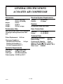
GENERAL SPECIFICATIONS
AC30A HYD AIR COMPRESSOR
Electrical System Requirements
Dimensions
Width:
Height:
Length:
Weight:
Voltage:
Current:
25.0 in. (AT TOP)
20.0 in. (AT BASE)
24.5 in.
28.25 in.
250 lbs. w/cage
12 Volts DC
2.5 Amps
Rotation
Bi-rotational Radial Fan Blade
Performance Data
Hose Connections
28.8* cfm (Free Air Cubic Feet per Minute) @
Pressure:
Return:
100 psig air outlet pressure and 1800
rpm.
-12 JIC MALE
-12 JIC MALE
Technical Data
Piston Displacement: 48.5 cfm
*Reference Conditions:
Absolute Inlet Pressure:
14.5 psi
Relative Air Humidity:0 %
Air Inlet Temperature:68° F.
Maximum Air Pressure:
145 psig
Nominal RPM:
1800 rpm
Crankcase Oil Capacity:
1.5 qts
Approx. Oil Consumption: .025 oz/hr
Maximum Temperature (@ Outlet): 165°F
Noise Level:
84 dB(A)
Hydraulic Requirements
Flow (Max):
Pressure:
Fluid Type:
Fluid viscosity:
12 gpm (45.4 l/min)
2500 psi (172 bar)
Anti-Wear Hydraulic
150 SSU @ 100°F
1-1.0.0
10/09
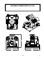
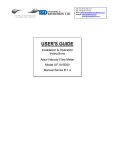
GENERAL DIMENSIONS AC30A
24.38
28.00
20.00
24.11
29.01
1-2.0.0
10/09
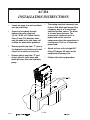
AC30A
INSTALLATION INSTRUCTIONS
1
Locate air pump in a well ventilated
area on truck body.
2
Secure to truck body through
bottom side rails using four
(4) 3/8- 24 NF x 2¾ Grade 5 bolts.
Four (4) new 7/16 diameter holes
may be made in the side frame rail
to allow for obstruction problems.
3
Remove plastic cap from “T” port in
the hydraulic valve block and install
return line to cooler or reservoir.
4
Remove plastic cap from “P” port
in the hydraulic valve block and
install pressure line from hydraulic
pump.
5
The mating electrical connector has
4 wires. Red, black and orange. Run
red power wire to a 10 amp fused
switched ignition source. The black
to a frame ground source. The
orange wire is optional and is a
power feed source from the
compressor when the compressor is
running only. This is a 10 amp max.
power feed.
6
Attach air hose to the straight 5/8"
fitting (37 degree JIC male) on the
compressor discharge line.
7
Follow initial start-up procedure.
1-3.0.0
10/09
OPERATION — AC30A
BASIC OPERATION
CAUTION: When the hydraulic system
shuts down a shock wave is delivered to
the return line. Locate the hydraulic
coolers and filters a minimum of 10’
away.
Air is drawn through the intake filter,
intake manifold and suction discs into
the cylinders. The air is compressed,
then discharged through the delivery
discs to the temperature reducer, where
the heat of the compressed air is partly
removed. From the temperature reducer
the compressed air is discharged
through the 5/8” JIC customer
connection points.
The pressure switch is preset to
specified settings.
Pressure Switch:
Shutoff:
150 psig
Restart:
110 psig
AUTO RUN MODE
When the demand for air is moderate, the
unit should be run in the auto mode.
This allows the compressor to produce
air until the pressure reaches the upper
limit of the pressure switch and stop. At
this point it shuts the compressor off.
When the tank pressure reduces to the
lower limit of the pressure switch the
unit will start up and continue producing
air.
1-4.0.0
10/09
AC30A
INITIAL START-UP PROCEDURE
1
Read the AC30A Owner’s Manual.
Check all wiring for loose
connections.
2
3
Check oil level in sight gauge. It
should be filled to the middle of the
sight glass. If not, fill to the proper
level. Fill with PAO synthetic
lubricant equivalent to Chevron-Gulf
GSL 838A or Summit SH-46. If
petroleum based crankcase oil is
required by operator, use an SAE
10W oil, API classification CD of SF,
Mil Spec MIL-L-2104C or MIL-L-46152.
4
Check that pressure switch operates
at the pressure limits specified.
5
Check the oil fill cap on top of
compressor (yellow knob) for
tightness.
6
Check hydraulic fluid flow.
CAUTION: More than 12 GPM will
build excess heat in the system.
7
CAUTION: Do not mix oil types.
1-5.0.0
10/09
Check all piping for leaks.
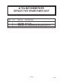
AC30A RECOMMENDED
SINGLE UNIT SPARE PARTS LIST
ITEM
QTY
PART NO.
DESCRIPTION
1
2
3
3
5
1
750107000 AIR FILTER
750097000 OIL, CRANKCASE (QT BOTTLES OF PAO OIL)
302688-012 COIL, HYD VALVE SOLENOID/RELIEF
1-6.0.0
10/09
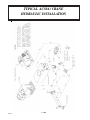
TYPICAL AC30A / CRANE
HYDRAULIC INSTALLATION
2-1.0.0
10/09
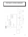
PNEUMATIC SYSTEM SCHEMATIC
2-2.0.0
10/09
AC30A ELECTRICAL SYSTEM
P/N: 200220-999
2-3.0.0
10/09
AIR/HYDRAULIC/ELECTRICAL
SCHEMATIC P/N: 701106
2-4.0.0
10/09
10/09
3-1.0.0
A
B
C
D
8
8
4
3
3
11
7
7
2
22
10
6
6
19
21
15
17
18
18
5
5
16
6
9
5
12
2
4
4
2
1
REV
1
7
13
14
3
PART NUMBER
MCM
MCM
ENG
2
Parts List
DESCRIPTION
1
ANGULAR ` 1°
DECIMAL ` .03
1/11/2006
DO NOT SCALE
TOLERANCES
UNLESS NOTED
2
D
SIZE
1=2
SCALE
200281
DWG NO
COMPR & PARTS, AC30
DESCRIPTION
PATH
G:\Inventor Files\200k\200281.dwg
THIS DRAWING AND ALL
0.000 TO 1.000 ` .010
INFORMATION THEREIN IS
1.001 TO 5.000 ` .015
THE PROPERTY OF
AUTOCRANE, IS
5.001 TO 10.000 `.020
CONFIDENTIAL AND MUST
10.001 & OVER `.025
NOT BEMADE PUBLIC OR
COPIED. IT IS LOANED
DRAWN
SUBJECT TO RETURN UPON
NDD
DEMAND, IS NOT TO BE USED CHECKED
DIRECTLY OR INDIRECTLY IN
ANYWAY DETRIMENTIAL TO MATERIAL
THE INTEREST OF AUTO
N/A
CRANE.
MACHINED SURFACES UNMACHINED SURFACES
NOMINAL DIM.
FRACTIONAL ` 1/16
1
SHEET
1
OF
1
2
REV
AUTO CRANE
P.O. BOX 580697
TULSA, OK 74158-0697
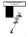
ELBOW, HYD 1/2 MJIC X -10 MSAE
MOTOR, HYD 1.29 A 3/4-RD SP CCW HP
WASHER, FLAT GR8 3/8
NUT, NYLOC GR8 3/8-16
HUB, DRIVE COUPLING R38(.750 DIA BORE).0005
SPIDER, DRIVE COUPLING R38
WASHER, LOC 8MM
BOLT, HEX GR10.9 8MM X 30MM
COMPR, 35 PISTON AC
ADAPTER, 1/2 BSPP X 1/2 NPT
BOLT, HEX GR8 3/8-16 X 3
ADAPTER, HYD MTD TO AC30 COMPR
WASHER, LOC GR8 3/8
BOLT, HEX GR8 3/8-16 X 1 1/4
ADAPTER, 3/8 MBSPT X 3/8 FNPT
HOSE, .500 OIL DRAIN AC30
HUB, DRIVE COUPLING 35MMX10X8MM KEY
CLAMP, HOSE 3/4 WORM GEAR
CAP, PIPE HEX 1/2 ZINC
ELBOW, HYD 3/4 MJIC X -12 MSAE
CONNECTOR, 1/2 BARB X 1/2 MNPT
SEAL, WASHER 1/2 MBSPP
PROPRIETARY INFORMATION
970408-088
305258
938206-071
925506-198
301266
301267
938808-200
929208-300
304760
302631
929806-300
305767
937806-094
929806-125
989206-038
302636
305434
300033-075
906030-020
970412-106
974808-050
308525
3/11/2011
7/7/2008
DATE
1
1
1
8
4
1
1
4
4
1
1
4
1
2
2
1
1.167 FT
1
2
1
1
1
1
1
2
3
4
5
6
7
8
9
10
11
12
13
14
15
16
17
18
19
20
21
22
ADDED 308525
REPLACED (2) 929806-100 WITH 929806-125
DESCRIPTION
REVISION HISTORY
8
QTY
3
ITEM
A
B
C
D
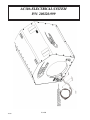
AC30A COMPR & PARTS SYS.
P/N: 200281-999
9
10
8
7
1
11
6
4
12
6
2
4
13
4
5
17
22
20
16
18
10
19
8
7
ITEM
QTY
PART NUMBER
1
1
962010-050
2
1
975104-012
3
3.083FT 302636
4
2
970308-050
5
1
964808-050
6
4
300033-075
7
4
929104-100
8
4
938604-071
9
1
305480
10
4
961504-090
11
1
974808-050
12
1
303815
13
2
975200-025
14
1
302613
15
1
943103-025
16
1
305463
17
1
970308-025
18
1
77041369
19
1
305162
20
1
305799
21
1
304998
22
1
307054
NS
1.083FT 89034176
21
14
15
DESCRIPTION
BULKHEAD, 5/8 JIC X 1/2 FNPT
ELBOW, COMPRSN 1/4 TUBE X 1/8 MNPT
HOSE, .500 OIL DRAIN GRAY 2
ELBOW, HYD .500 BARB X .500 MNPT
TEE, PIPE 1/2F X 1/2M X 1/2F
CLAMP, HOSE 3/4 WORM GEAR
BOLT, HEX GR5 1/4-20 X 1
WASHER, FLAT GR5 1/4
BRACKET, AIR DISCHARGE AC30 06 (REV 1)
NUT, TINNERMAN 1/4-20
CONNECTOR, 1/2 BARB X 1/2 MNPT
VALVE, CHEC K 1/2
INSERT, COMPRSN FITTING 1/2 BRASS
CLIP, 1/2" HYD HOSE HOLDER
RIVET, POP 3/16 X 1/2 ALUMINUM
BRACKET, GAUGE & LIGHT (REV 2)
ELBOW, HYD 1/2 BARB X 1/4 MNPT
SWITCH, PRESSURE WITH UNLOADER F
CAP, 7/8 ID PLASTC
GROMMET, 3/4 OD X 1/2 ID X 1/8 THICK
GAUGE, 0-200 PSI 1/4 MNPT LIQUID FILLED
TEE, .250MNPT X .250MNPT X .250FNPT
TUBE, AIR BRAKE .25
Parts List
AC30A DISCHARGE & PARTS SYS.
P/N: 200283-999
3-2.0.0
10/09
10/09
10
11
7
10
12
9
8
1
2
5
7
13
4
6
3
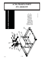
DESCRIPTION
CONNECTOR, 1/2 MJ IC X -12 MSAE
CONNECTOR, 3/4 MJ IC X -12 MSAE
FRAME, AC30 06 (REV 1)
ISOLATOR, 60A HARD BULLET (REV 2)
WASHER, ISOLATOR 60A HARD (REV 2)
BOLT, HEX GR5 1/4-20 X 3 1/4
WASHER, FLAT GR5 1/4
KIT, HYD VALVE BLOCK 13GPM FLOW CONTROL
PLUG, 12 SAE PLASTIC
NUT, TINNERMAN 1/4-20
BRACKET, VALVE BLK 35 PISTON A (REV 2)
BOLT, HEX GR5 1/4-20 X 1
PLATE, VIBRATION ISOLATOR AC30
ORIFICE, SILVER .215
Parts List
3-3.0.0
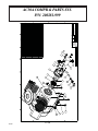
200280-999 (REV 1)
NOTE:
WHEN REPLACING HYDRAULIC
VALVE BLOCK (P/N 80056-13-12),
YOU MUST REMOVE ORIFICE
(P/N 306812-215) FROM THE OLD
BLOCK AND INSTALL ON THE
NEW BLOCK.
ITEM QTY PART NUMBER
1
1 970508-106
2
1 970512-106
3
1 305479
4
4 300540-001
5
4 300541-001
6
2 929104-325
7
4 938604-071
8
1 80056-13-12
9
2 988912-106
10
4 961504-090
11
1 304762
12
2 929104-100
13
1 304930
NS
1 306812-215
AC30A FRAME & PARTS
P/N: 200280-999
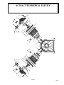
AC30A CYLINDERS & VALVES
3-4.0.0
10/09
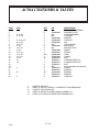
AC30A CYLINDERS & VALVES
ITEM
1
2
3
4
5
6
7
8
9
10
11
12
13
14
15
16
17
18
19
20
21
22
23
24
KITS
III, VI, VII
III, VI, VII
III, IV, VI, VII
III, VI, VII
II, VI, VII
VI, VII
II, VI, VII
VI, VII
II, VI, VII
II, VI, VII
II, VI, VII
VI, VII
VI
VII
II
VI
II
QTY
1
8
1
1
8
8
4
2
2
2
2
2
A/R
2
10
1
1
4
1
2
4
10
4
4
II
III
IV
VI
VI
DESCRIPTION
CRANKCASE ASSEMBLY
SCREWED STUD
PISTON ASSEMBLY
CYLINDER
WASHER
LOCK NUT
PIN
SUCTION DISC
VAVLE SEAT
DELIVERY DISC
GUARD
SPRING
CORD
O-RING
BOLT
CYLINDER HEAD LLP
CYLINDER HEAD RLP
BOLT
INLET SILENCER (SEE Aw-461)
GASKET
WASHER
WASHER
WASHER
LOCK NUT
= PART OF VALVE KIT
= PART OF PISTON + RINGS + CYLINDER KIT, LOW PRESSURE
= PART OF PISTON RING KIT
= PART OF PISTON, CYLINDER HEAD ASSEMBLY LH
I= PART OF PISTON, CYLINDER HEAD ASSEMBLY RH
3-4.1.0
10/09
P/N
N/A
755080-001
N/A
N/A
755080-002
755080-003
755080-004
N/A
755080-005
N/A
755080-006
755080-007
755080-008
755080-009
755080-010
755080-011
755080-012
755080-013
REF
755080-014
755080-015
755080-002
755080-016
755080-017
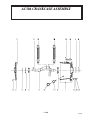
AC30A CRANKCASE ASSEMBLY
3-5.0.0
10/09
AC30A CRANKCASE ASSEMBLY
ITEM
KITS
QTY
P/N
1
1
755080-018
CRANKCASE
2
1
755080-019
BEARING HOUS ING
DESCRIPTION
3
V
1
N/A
4
V
1
755080-020
BEARING
5
V
1
755080-021
BEARINH
6
V
1
755080-022
SEAL
7
V
1
755080-023
SEAL
1
755080-024
RETAINER
1
755080-025
O-RING
10
10
755080-026
BOLT
11
2
755080-027
DOWELL PIN
12
1
755080-028
NIPPLE
13
1
755080-029
SIGHT GLASS
14
1
755080-030
GASKET
15
1
755080-031
BREATHE R FLANGE
16
6
755080-032
BOLT
8
9
V
CRANKSHAFT
17
V
1
755080-033
WOODRUFF KEY
18
V
1
755080-034
CONNECTING ROD LEFT
19
V
1
755080-035
CONNECTING ROD RIGHT
20
1
755080-036
GASKET
21
1
755080-037
CAP
V = PART OF CRANKSHAFT + CONNECTING ROD KIT
3-5.1.0
10/09
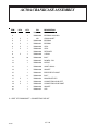
AC30A PISTON ASSEMBLY
ITEM
KITS
QTY
P/N
DESCRIPTION
1
-
1
N/A
CONNECTING ROD
2
III
1
N/A
PISTON
3
III
2
755080-038
CIRCLIP
4
IV
1
N/A
RING SCRAPER
5
IV
1
N/A
RING COMPRESSION
6
IV
1
N/A
RING COMPRESSION
7
VI, VII
1
755080-039 GUDGEON PIN
III = PART OF PISTON + RINGS + CYLINDER KIT, LOW PRESSURE
IV = PART OF PISTON RING KIT
VI = PART OF PISTON, CYLINDER HEAD ASSEMBLY LH
VII = PART OF PISTON CYLINDER HEAD ASSEMBLY RH
3-6.0.0
10/09
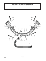
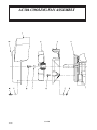
AC30A COOLING SYSTEM
3-7.0.0
10/09
AC30A COOLING SYSTEM
ITEM
DESCRIPTION
QTY
P/N
1
2
755080-040
CONNECTION PIPE
2
1
755080-041
DELIVERY PIPE
3
2
755080-042
BOLT
8
755080-043
WASHER
5
4
755080-044
CAPNUT
6
1
755080-011
CYLINDER HEAD LH
2
755080-045
O-RING
8
2
755080-046
O-RING
9
2
755080-047
BOLT
10
1
755080-012
CYLINDER HEAD RH
11
1
755080-048
COUP LING
12
1
755080-049
FLAT GASKET
4
7
KI TS
II, V, VI,VII
II, V, VI,VII
II
V
VI
VII
= PART OF VALVE KIT
= PART OF CRANKSHAFT + CONNECTING ROD KIT
= PART OF PISTON, CYLINDER HEAD ASSEMBLY LH
= PART OF PISTON, CYLINDER HEAD ASSEMBLY RH
3-7.1.0
10/09
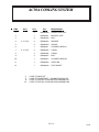
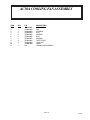
AC30A COOLING FAN ASSEMBLY
3-8.0.0
10/09
AC30A COOLING FAN ASSEMBLY
ITEM
1
2
3
4
5
6
7
8
9
10
11
QTY
1
1
1
6
6
1
1
4
1
1
1
P/N
755080-051
755080-052
755080-053
755080-054
755080-055
755080-056
755080-057
755080-058
755080-059
755080-060
N/A
DESCRIPTION
FAN HOUSING
FAN
HOUSING
BOLT
WASHER
BOLT
WASHER
TAPTITE BOLT
LOCK NUT
LABEL
CRANKCASE ASSEMBLY
3-8.1.0
10/09
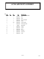
AC30A AIR INLET ASSEMBLY
3-9.0.0
10/09
AC30A AIR INLET ASSEMBLY
ITEM
QTY
P/N
DESCRIPTION
1
1
N/A
CRA NKCASE ASSEMBLY
2
1
755080-061
PIPE
3
2
755080-062
SEAL
4
1
755080-063
INLET SILENCER
5
1
755080-064
LABEL
6
A/R
755080-065
O-RING CORD
7
1
755080-066
FILTE R HOUSING
1
750107
9
1
755080-067
COVER
10
1
755080-068
COVER
11
4
755080-069
BOLT
12
8
755080-055
WASHER
13
4
755080-059
LOCK NUT
14
1
755080-070
PLUG
8
KIT
I
AIR FILTER
3-9.1.0
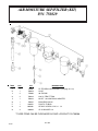
10/09
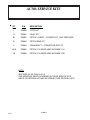
AC30A SERVICE KITS
KIT
P/N
I
755060
FILTER KIT
II
755061
VALVE KIT
III
755062
PISTON + RINGS + CYLINDER KIT, LOW PRESSURE
IV
755063
PISTON RING KIT
V
755064
CRANKSHAFT + CONNECTING ROD KIT
VIVII
755065
PISTON, CYLINDER HEAD ASSEMBLY LH
VII
755066
PISTON, CYLINDER HEAD ASSEMBLY RH
DESCRIPTION
NOTE:
SEE PAGE 3-4.0.0 THRU 3-9.1.0
FOR INDIVIDUAL PARTS CONTAINED IN THESE SERVICE KITS.
PARTS OF A SERVICE KIT MAY BE SPREAD OVER SEVERAL LISTS.
3-10.0.0
10/09
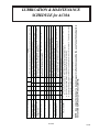
½
X
X
2
X
YEARS
NOTES
EVERY 6000 RUN HOURS
HIGH TEMPERATURES AND EXTENDED SERVICE MAY SHORTEN
THE TIME BETWEEN HYDRAULIC OIL CHANGES.
CHANGE HYDRAULIC SYSTEM FILTER
FOR PAO (SYNTHETIC) OIL EVERY 3000 RUN HOURS
FOR MINERAL BASED OIL EVERY 1000 RUN HOURS
REPLACE AIR FILTER AFTER EVERY 600 RUN HOURS
REMOVE AND CLEAN WITH COMPRESSED AIR
ON-OFF PRESSURES SHOULD BE VERIFIED FOR CONSISTENCY.
FURNAS SWITCH ADJUSTMENT.
SUDDEN CHANGE IN PERFORMANCE INDICATES A PROBLEM MAY
BE DEVELOPING. INVESTIGATE PROBLEM.
WITH POWER OFF, OPEN DRAIN DEVICE TO PURGE WATER
SHOULD BE IN LOWER HALF OF SIGHT GLASS
(When both run hours and interval are shown, use whichever comes first!)
NOTE: Use only authorized parts. Any damage or malfunction caused by the use of unauthorized parts is
not covered by Warranty or Product Liability.
* RECOMMENDED CRANKCASE OILS: SEE INITIAL START-UP PROCEDURE
CAUTION
REPLACE VALVE DISCS
1
YEAR
{ In the event that the unit runs over pressure, the safety valve would reduce the tank pressure to a save level.
Be sure it will work properly. Never run the unit without this safety valve.
{ Do not use petroleum based or other flammable solvents for cleaning.
{ Routine maintenance insures trouble-free operation and protects your investment. All warranties are void if
maintenance is neglected.
X
CHECK HYD FILTER
CHANGE HYD OIL
X
CHANGE CRANK OIL *
X
INSPECT AIR FILTER
X
CHECK COMPRESSOR
OPERATION
X
X
PER
MONTH YEAR
CHECK SETTINGS
X
DRAIN AIR TANK
DAILY
CHECK OIL LEVEL
SERVICE PERFORMED
LUBRICATION & MAINTENANCE
SCHEDULE for AC30A
4-1.0.0
10/09
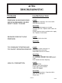
AC30A
TROUBLESHOOTING
CAUSE/SOLUTION
PROBLEM
COMPRESSOR DOES NOT START.
CAUSE:
No electrical power.
Receiver pressure between starting and
stopping pressures.
SOLUTION:
Check or have electrical system checked.
Wait until pressure drops.
COMPRESSOR DOES NOT PUMP.
CAUSE:
Furnas Switch open.
Solenoid valve not energized.
SOLUTION:
Have electrician check wiring.
INSUFFICIENT AIR RECEIVER
PRESSURE.
CAUSE:
Air leak(s).
Air intake filter clogged.
Air consumption exceeds unit capability.
Pressure gauge defective.
SOLUTION:
Check for air leak(s) and correct as necessary.
Clean or replace intake filter.
Decrease demand or add unit.
Replace gauge.
Disassemble and clean.
INSUFFICIENT PRESSURE AT
POINT OF USE.
CAUSE:
Leaks or restrictions.
Air filter clogged.
Service hose too small.
Excessive air requirement.
SOLUTION:
Check hose and piping.
Clean or replace air filter.
Replace with larger hose.
4-2.0.0
10/09
AC30A
TROUBLESHOOTING
PROBLEM
CAUSE/SOLUTION
PRESSURE IN RECEIVER RISES
ABOVE MAXIMUMAND CAUSES
SAFETY VALVE TO BLOW.
CAUSE:
Furnas switch incorrectly set or out or order.
Solenoid valve defective.
SOLUTION:
Set switch to stop compressor at rated
maximum pressure. Replace switch it does not
respond.
Remove and test valve on outside mains supply
line. Replace, if out of order.
RECEIVER DOES NOT HOLD
PRESSURE.
CAUSE:
Discharge check valve leaks.
SOLUTION:
Replace.
TOO FREQUENT STARTING AND
TOO SHORT OPERATING PERIODS.
CAUSE:
Air pressure switch incorrectly set.
Discharge check valve leaks.
High condensate level in receiver.
SOLUTION:
Increase pressure.
See LOADING PERIODS TOO LONG (page 93.0.0).
Drain condensate more frequently.
HIGH OIL CONSUMPTION.
CAUSE:
Oil level too high.
Breather valve malfunctioning.
Piston ring(s) worn or broken.
Intake filter clogged.
SOLUTION:
Do not overfill crankcase. Keep level within
lower half of sight glass.
Check valve.
4-2.1.0
10/09
AC30A
TROUBLESHOOTING
PROBLEM
CAUSE/SOLUTION
LOADING PERIODS TOO LONG
CAUSE:
Excessive air consumption.
Compressor not in optimum condition.
Sticking or damaged valves.
SOLUTION:
Decrease consumption.
Have compressor inspected.
4-2.2.0
10/09
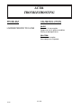
AC30A
TROUBLESHOOTING
SET UP
SYSTEM TEST
1 Install flow meter in Port “A” high
pressure line to the hydraulic motor.
1 Engage PTO and raise the truck engine
RPM to the proper setting without
starting the air compressor. Record the
main hydraulic flow through Port “A”
and the system pressure. Record
hydraulic motor/compressor RPM with
a phototach.
2 Install a 3000 psig pressure gauge in
Port “A” before the flow meter. This
will read system pressure. Install a
piece of reflective tape to the drive
coupling at the top access hole.
2 With air compressor running, and the
air tank pressure anywhere from 30 to
100 psig, record the main hydraulic
flow through Port “A” and the max
system pressure. The main flow
should be a maximum of 12 gallons per
minute. The max system pressure
should be 2500 psig on startup and
then from 1800 to 2000 psig while
running. The motor flow should be 12
gallons per minute.
4-3.0.0
10/09
AC30A
TROUBLESHOOTING
7 If the air compressor fails to start and
the hydraulic pressure is low:
A. Check the red power wire for + 12
volts DC.
8
If the compressor fails to start and
the hydraulic pressure is high:
A. Check power to hydraulic
solenoid coil at Furnas switch
B. Check to see if the air tank 9 If the motor flow is 12 GPM and the
compressor is turning less than 1700
pressure is higher than the system
RPM the motor has degraded enough
reset pressure (usually 110 psig).
to allow hot oil to pass through
C. Remove the ventable relief valve
without producing speed. Rebuild or
and check for contamination holding
replace motor.
the valve in the open condition.
Check for o-ring damage.
4-3.1.0
10/09
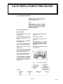
VALVE REPLACEMENT PROCEDURE
4-4.0.0
10/09
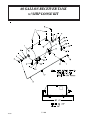
60 GALLON RECEIVER TANK
w/ SHIP LOOSE KIT
5-1.0.0
10/09
60 GALLON RECEIVER TANK
w/ SHIP LOOSE KIT
DESCRIPTION
ITEM
QTY
P/N
1
1
750201
2
1
750205-006
GAUGE, 0-200 PSI AIR
3
1
750447
FITTING, ELL GAUGE
4
2
750423
REDUCER, PIPE THREAD
5
1
360263
ELL, 90º - (AIR OUT)
6
1
000209
PLUG, PIPE 1/4 NC
7
3
750426
PLUG, 3/4 DRYSEAL PIPE
8
1
750459
TUBE, ASSEMBLY
9
1
750715
VALVE, DRAIN
10
1
750428
ELL. 90º - (AIR IN)
11
2
002200
SCREW, RD HD #10
12
2
750191
CLAMP, PLASTIC
13
2
019800
WASHER, SP LK #10
14
2
015600
NUT, HEX #10
15
2
750202
TUBE, SUPPORT
*16
2
750430
FITTING, #10 PUSH-ON/ JIC FEM
*17
1
750209-192
*18
1
750479
ELL, 90º -10 FEM SWIVEL/ JIC
*19
1
750429
ELL, BULKHEAD 90º -10 JIC
*20
4
009101
BOLT, HEX HD 3/8 NF x 2 3/4" LG G5
*21
4
021200
WASHER, FLA T, 3/8
*22
4
021101
WASHER, SP LK 3/8
*23
4
017100
NUT, HEX 3/8 NF
24
2
750490
REDUCER, PIPE --32 NPT/---24 NPTF
NOTE:
TANK, 60 GAL HORZ RECEIVER
HOSE, 10 PUSH-ON, LOW PRESSURE
ITEMS MARKED WITH AN ASTERISK (*)
ARE CONTAINED IN SHIP LOOSE KIT P/N 750186.
5-1.1.0
10/09
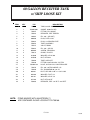
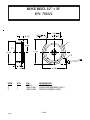
30 GALLON RECEIVER TANK
w/ SHIP LOOSE KIT
5-2.0.0
10/09
30 GALLON RECEIVER TANK
w/ SHIP LOOSE KIT
ITEM
QTY
P/N
1
1
750200
2
1
750205-006
GAUGE, 0-200 PSI AIR
3
1
750447
FITTING, ELL GAUGE
4
2
750423
REDUCER, PIPE THREAD
5
1
360263
ELL, 90º - (AIR OUT)
6
1
000209
PLUG, PIPE 1/4 NC
7
3
750426
PLUG, 3/4 DRYSEAL PIPE
8
1
750459
TUBE, ASSEMBLY
9
1
750715
VALVE, DRAIN
10
1
750428
ELL. 90º - (AIR IN)
11
2
002200
SCREW, RD HD #10
12
2
750191
CLAMP, PLASTIC
DESCRIPTION
TANK, 30 GAL HORZ RECEIVER
13
2
019800
WASHER, SP LK #10
14
2
015600
NUT, HE X #10
15
2
750202
TUBE, SUPPORT
*16
2
750430
FITTING, #10 PUSH-ON/ JIC FEM
*17
1
750209-192
*18
1
750479
ELL, 90º -10 FEM SWIVEL/ JIC
*19
1
750429
ELL, BULKHEAD 90º -10 JIC
*20
4
009101
BOLT, HEX HD 3/8 NF x 2 3/4" LG G5
*21
4
021200
WASHER, FLAT, 3/8
*22
4
021101
WASHER, SP LK 3/8
*23
4
017100
NUT, HE X 3/8 NF
NOTE:
HOSE, 10 PUSH-ON, LOW PRESSURE
ITEMS MARKED WITH AN ASTERISK (*)
ARE CONTAINED IN SHIP LOOSE KIT P/N 750186.
5-2.1.0
10/09
AIR MOISTURE SEP/FILTER (KIT)
P/N: 750829
DESCRIPTION
ITEM
QTY
P/N
1
1
750205
FILTER/REG/ LUB ASSEMBLY (see page 6-1.1.0)
*2
1
750209
HOSE
3
2
750404
90º ELBOW
*4
2
750430
#10 JIC FEM FITTING
5
1
750444
#2 NPT / #4 COM BRASS ADAPTER
*6
1
750445
BULKHEAD UNION
*7
1
340959
PLASTIC TUBING
*8
4
005800
HEX HD SCREW 1/4 NC x 1 1/2
*9
4
020200
SP LK WASHER 1/4
* THESE ITEMS CAN BE PURCHASED AS SHIP LOOSE KIT P/N 750206
6-1.0.0
10/09
FILTER/REGULATOR/LUBRICATOR
ASSEMBLY P/N: 750205
* THESE ITEMS ARE NOT INCLUDED IN P/N 7502005 AND ARE NOT SHOWN ON ILLUSTRATION
DESCRIPTION
ITEM
QTY
P/N
1
1
750205-001
FILTER
2
1
750205-002
REGULATOR
3
1
750205-003
LUBRICATOR
4
1
750205-004
SHUT OFF VALVE
5
1
750205-005
AUTO DRAIN
6
1
750205-006
GAGE 0-160 PSI
7
1
750205-007
1/2” NPT END
8
2
750205-008
SLEEVE w/ MTG BRACKET
9
2
750205-009
SLEEVE
REPLACEMENT/MAINTENANCE PARTS
*10
750205-010
STANDARD 5 MICRON FILTER
*11
750205-014
SEAL KIT COMPLETE w/ O-RINGS, SEALS,
ELEMENT
*THESE ITEMS ARE NOT INCLUDED IN P/N 750205 AND ARE NOT SHOWN ON ILLUSTRATION.
6-1.1.0
10/09
FILTER/REGULATOR/LUBRICATOR
P/N: 751277
NOTE: F/R/L IS PURCHASED AS AN ASSEMBLY; (-XXX) DASH
NUMBERS ARE FOR REPLACEMENT PARTS.
DESCRIPTION
ITEM
QTY
P/N
1
1
751277-001
FILTE R/REGULA TOR
2
1
751277-002
LUBRICATOR
3
2
751277-003
JOINER SET w/ T-BRK T
4
1
751277-004
SAFETY LOCKOUT VALVE
5
5
751277-005
END BLOCK, 3/4 NP T
6
1
751277-006
PRESS, GAUGE 0-300 PSI
7
1
751277-007
FILTE R ELEMENT
8
1
751277-008
AUTO MECH DRAIN (F/R)
9
1
751277-009
METAL BOWL (F/R)
10
1
751277-010
METAL BOWL (LUB)
11
2
751277-011
BOWL O-RING
12
1
751277-012
O-RING, FILL PLUG
6-2.0.0
10/09
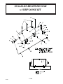
AC30A WEATHER GUARD
INSTALLATION
7-1.0.0
10/09
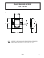
HOSE REEL 1/2" x 50’
P/N: 750212
ITEM
1
2
3
QTY
1
1
1
P/N
750212
750212-002
750212-003
DESCRIPTION
HOSE REEL
GUIDE ARM ASSEMBLY (REF.)
SWIVEL ASSEMBLY (REF.)
7-2.0.0
10/09
HOSE ROLLER GUIDE
P/N: 750213
NOTE: THIS PART IS USED WHEN HOSE REEL IS INSTALLED IN A BODY
COMPARTMENT AND HOSE IS TO EXIT THRU THE BODY.
7-3.0.0
10/09
P.O. Box 580697 * Tulsa, OK 74158-0697
4707 N. Mingo Rd. * Phone (918) 836-0463
LIMITED WARRANTY
2 YEAR PARTS AND LABOR
Auto Crane will warranty to the consumer for a period of (2) years parts and labor from the date
of purchase. Each new Auto Crane unit they sell will be free under normal use and service from
defects in material and workmanship. Date of purchase will be honored as the date indicated on
the Bill of Sale, which must accompany the Warranty Registration and be on file with Auto
Crane. Absent a valid Warranty Registration and appropriate documentation, the original date
of manufacture, as indicated by the serial number on the product, will be used to determine the
effective date of the 2 year warranty.
The obligation of Auto Crane under this warranty is limited to the replacement or repair of parts
that appear to the manufacturer after review and/or inspection to be defective and paid flat rate
labor for replacing defective parts. This warranty does not obligate Auto Crane to bear the travel
time charges in connection with the replacement or repair of defective parts. Responsibility for
customer’s claims arising from misapplication, abuse, misuse or alteration of equipment or
parts lies with the distributor or user and no warranty obligation is assumed in these circumstances
by Auto Crane.
Auto Crane will in no event be liable for any consequential damages or contingent liabilities
arising out of the failure of any Auto Crane Product or parts to operate properly.
Auto Crane makes no warranty in respect to component accessories, it being subject to the
warranties of their respective manufacturers.
If field service, at the request of the distributor, is rendered and fault is found not to be with Auto
Crane’s product, the distributor shall pay the time and expense of the field representative.
Claims for service labor or other expenses that have incurred by the buyer without approval or
authorization or Auto Crane will not be accepted.
When applying for warranty, claims may be handled by contacting your nearest authorized Auto
Crane Distributor. All claims are to be filed in writing on an Auto Crane Warranty Claim
Form.
AUTO CRANE COMPANY IS UNDER NO OLIGATION TO EXTEND THIS WARRANTY
TO ANY CUSTOMER FOR WHICH AN AUTO CRANE DELIVERY REPORT FORM
HAS NOT BEEN COMPLETED AND ON FILE WITH AUTO CRANE COMPANY
Limited Warranty 2 Years
10/09
Effective September 2, 2003