1
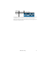
Freekie
user manual
© 2004 Martin Professional A/S, Denmark.
All rights reserved. No part of this manual may be
reproduced, in any form or by any means, without
permission in writing from Martin Professional A/S,
Denmark.
Printed in Denmark.
P/N 35000113, Revision E
Introduction . . . . . . . . . . . . . . . . . . . . . . . . . . . . . . . . . . . . . . . . . . . . . . . . 5
Features . . . . . . . . . . . . . . . . . . . . . . . . . . . . . . . . . . . . . . . . . . . . . . . . . . . 5
Safety precautions . . . . . . . . . . . . . . . . . . . . . . . . . . . . . . . . . . . . . . . . . . . 5
Installation . . . . . . . . . . . . . . . . . . . . . . . . . . . . . . . . . . . . . . . . . . . . . . . . . 7
Power . . . . . . . . . . . . . . . . . . . . . . . . . . . . . . . . . . . . . . . . . . . . . . . . . . . . .
Connecting the serial link . . . . . . . . . . . . . . . . . . . . . . . . . . . . . . . . . . . . . .
About serials links . . . . . . . . . . . . . . . . . . . . . . . . . . . . . . . . . . . . . . .
To build the serial link . . . . . . . . . . . . . . . . . . . . . . . . . . . . . . . . . . . .
7
7
7
8
DMX address setting. . . . . . . . . . . . . . . . . . . . . . . . . . . . . . . . . . . . . . . . 9
Controller set-up . . . . . . . . . . . . . . . . . . . . . . . . . . . . . . . . . . . . . . . . . . 12
Fixture set-up . . . . . . . . . . . . . . . . . . . . . . . . . . . . . . . . . . . . . . . . . . . . . .
Strobe set-up. . . . . . . . . . . . . . . . . . . . . . . . . . . . . . . . . . . . . . . . . . . . . . .
Smoke set-up . . . . . . . . . . . . . . . . . . . . . . . . . . . . . . . . . . . . . . . . . . . . . .
Follow-spot set-up. . . . . . . . . . . . . . . . . . . . . . . . . . . . . . . . . . . . . . . . . . .
Giving names to banks . . . . . . . . . . . . . . . . . . . . . . . . . . . . . . . . . . . . . . .
Restoring bank names . . . . . . . . . . . . . . . . . . . . . . . . . . . . . . . . . .
12
13
14
14
15
15
Programming shows. . . . . . . . . . . . . . . . . . . . . . . . . . . . . . . . . . . . . . . 16
Programming a show . . . . . . . . . . . . . . . . . . . . . . . . . . . . . . . . . . . . . . . . 16
Playback . . . . . . . . . . . . . . . . . . . . . . . . . . . . . . . . . . . . . . . . . . . . . . . . . . 18
Running a show . . . . . . . . . . . . . . . . . . . . . . . . . . . . . . . . . . . . . . . . . . . .
Execution using programmed scene times . . . . . . . . . . . . . . . . . . .
Music trigger execution . . . . . . . . . . . . . . . . . . . . . . . . . . . . . . . . . .
MIDI triggering . . . . . . . . . . . . . . . . . . . . . . . . . . . . . . . . . . . . . . . .
Manual control of individual fixtures during show playback . . . . . . . . . . .
Intensity control . . . . . . . . . . . . . . . . . . . . . . . . . . . . . . . . . . . . . . . . . . . . .
Blackout . . . . . . . . . . . . . . . . . . . . . . . . . . . . . . . . . . . . . . . . . . . . . . . . . .
Dynamically modifying fade times. . . . . . . . . . . . . . . . . . . . . . . . . . . . . . .
Follow spot . . . . . . . . . . . . . . . . . . . . . . . . . . . . . . . . . . . . . . . . . . . . . . . .
Smoke effects . . . . . . . . . . . . . . . . . . . . . . . . . . . . . . . . . . . . . . . . . . . . . .
Strobe effects . . . . . . . . . . . . . . . . . . . . . . . . . . . . . . . . . . . . . . . . . . . . . .
18
18
18
18
19
20
20
20
20
21
21
Administrative functions. . . . . . . . . . . . . . . . . . . . . . . . . . . . . . . . . . . 22
Locking edit functions . . . . . . . . . . . . . . . . . . . . . . . . . . . . . . . . . . . . . . . .
Activating the PIN-code lock . . . . . . . . . . . . . . . . . . . . . . . . . . . . . .
Deactivating the PIN-code lock. . . . . . . . . . . . . . . . . . . . . . . . . . . .
Clearing Freekie memory . . . . . . . . . . . . . . . . . . . . . . . . . . . . . . . . . . . . .
22
22
22
22
Troubleshooting . . . . . . . . . . . . . . . . . . . . . . . . . . . . . . . . . . . . . . . . . . . 23
Specifications . . . . . . . . . . . . . . . . . . . . . . . . . . . . . . . . . . . . . . . . . . . . . 24
1
I NTRODUCTION
Thank you for selecting the Martin Freekie. This ruggedly built, easy to use
controller offers 12 fixture DMX control and multiple triggering options.
Freekie allows control of up to 12 fixtures (or fixture groups, where each fixture
group comprises similar fixtures that mimic each others’ behavior). Each fixture or
group is controlled with 12 channels. A joystick is provided for easy pan/tilt
adjustment. The Freekie can also control strobe and smoke fixtures. A master fader
allows you to instantly fade all fixtures, and there are multi-purpose buttons which
you can customize to control additional DMX units.
For audio-controlled shows there is the choice of either external signal input or the
Freekie's own internal microphone.
FEATURES
•
•
•
•
•
•
•
•
•
•
•
•
•
•
Controls up to 12 fixtures (or fixture groups), each with 12 channels
10 banks of 12 programmable shows, each show with up to 10 scenes
7-character bank naming
MIDI triggering of shows
Follow-spot functionality
Blackout
Pitch fader allowing instant speed adjustment during playback of a show
Joystick for easy pan/tilt control
Master fader for all fixtures
Musical triggering of scene changes: Built-in microphone or external control
signal input
Strobe and smoke fixture control
Control any DMX512 compatible intelligent light
Solid steel construction
Table or 19” rack mount
SAFETY PRECAUTIONS
• The Freekie is not for domestic use.
• Use the device only as described.
• Do not expose the device to rain or moisture.
Introduction
5
•
•
•
•
6
Make sure the device is properly grounded.
Do not operate the device with the cover removed.
Immediately repair or replace damaged power cords.
There are no user-serviceable parts inside; refer all service to a qualified
technician.
Introduction
2
I NSTALLATION
The Freekie comes with the following:
• 9 volt, 1 amp transformer
• User manual
POWER
The device is powered by a 9 volt DC transformer that is supplied with the product.
Connect this to a mains supply and plug it into the DC9V input at the back of the
Freekie.
Note
If the plug on the transformer supplied does not match those in
use in your country you may need to purchase an adaptor.
Alternatively, any 9 volt DC transformer with an output of 1 amp
can be used.
CONNECTING THE SERIAL LINK
About serial s li nks
The Freekie sends instructions through a serial data link. The link goes from the
controller’s output to the input of the first lighting fixture and then from the
fixture’s output to the input of the next fixture. It continues output-to-input in a
daisy-chain to all fixtures.
Up to 32 fixtures can be placed on a serial link without amplification.
Adaptor cables may be required when building the data link. There are two
differences to be aware of. First, both 3-pin and 5-pin XLR sockets are common.
(Martin fixtures have 3-pin XLR sockets. On fixtures that have 5-pin XLR sockets,
pins 4 and 5 are not used.)
Installation
7
T o bu il d th e seri al l in k
1.
Use shielded twisted-pair cable. A reliable data connection begins with the right
cable. Microphone cable cannot transmit DMX data reliably over long runs. For best
results, use only cable designed for RS-485 applications. Your Martin dealer has a
range of cables, connectors, and adaptors designed for lighting control.
2.
Starting from the controller, connect output to input. Four parallel DMX outputs, two 3-pin, and two 5-pin are provided on the Freekie.
3.
Never use a “Y” connector to split the link. If you need to split the serial link
into branches use a dedicated splitter/amplifier such as the Martin 4-Channel
Opto-Isolated RS-485 Splitter.
4.
Don’t overload the link. Placing more than 32 devices on a link can cause
unpredictable performance.
5.
Always terminate the link by installing a termination plug in the output socket
of the last fixture on the link. The termination plug, which is a male XLR connector with a 120 ohm resistor soldered between pins 2 and 3, “soaks up” the control signal so it cannot reflect back down the link. If a splitter is used, terminate
each branch of the link.
8
Installation
DMX ADDRESS SETTING
3
Each fixture connected to the serial link must have a DMX address, also known as a
start channel, which is the first channel the controller uses to send instructions to the
fixture. Fixtures of the same type that share the same address will mimic each
others behavior.
Freekie allows control of up to 12 fixtures or fixture groups. (A fixture group
comprises similar fixtures with the same DMX address.) The Freekie can control
the first 12 channels of each fixture, or group, and can activate smoke and strobe
fixtures. The Freekie assigns 12 channels to each fixture regardless of how many
channels it uses, therefore the DMX addresses have been pre-defined.
Assign the following addresses using the procedure that is required for each fixture
(refer to the user documentation for the fixture if you are in doubt as to the
procedure). The address is often set on the fixture using a DIP-switch, while others
use electronic address setting.
Freekie
fixture ID
DMX address DIP switch setting
1
1
2
13
3
25
4
37
DMX address setting
9
Freekie
fixture ID
10
DMX address DIP switch setting
5
49
6
61
7
73
8
85
9
97
10
109
11
121
12
133
Strobe
145
DMX address setting
Freekie
fixture ID
Smoke
DMX address DIP switch setting
157
If independent control is not required, two or more identical fixtures may use the
same address. They will receive the same instructions and behave identically.
Make a note of the fixtures and the fixture ID that they have been assigned to. You
will need this to set up the controller.
DMX address setting
11
CONTROLLER SET- UP
4
FIXTURE SET-UP
1 Press and hold EDIT for 3 seconds.
2 If the PIN-code function is enabled (see “Administrative functions” on page 22), you
will be prompted to enter the PIN code (factory set as “221174”). Use the fixture
buttons to select numbers. Press ENTER.
3 Press FIXTURE so that the red indicator is lit.
4 Select a fixture to be set-up (and any other fixture of the same type) using the
numbered buttons, 1-12. You can select a range of fixtures by pressing and holding
the first and last fixture buttons.
5 Press ENTER.
6 Specify the pan channel by moving the fader that corresponds to the pan channel of
the luminaire (refer to the DMX protocol in the luminaire’s user manual to find this),
and then press ENTER.
7 Specify the tilt channel by moving the fader that corresponds to the tilt channel of the
luminaire (refer to the DMX protocol in the luminaire’s user manual to find this), and
then press ENTER.
12
Controller set-up
8 Specify the dimmer/intensity channel by moving the fader that corresponds to the
dimmer/intensity channel of the luminaire (refer to the DMX protocol in the luminaire’s
user manual to find this), and then press ENTER.
9 Using the same fader set the minimum dimmer intensity value and press ENTER.
10 Using the same fader set the maximum dimmer intensity value and press ENTER.
11 You have now completed set up of this/these fixture/s. If:
• There are additional fixtures to set up then go back to step 4 and repeat these
steps.
• You have completed fixture configuration, then press EDIT to leave fixture set up
mode.
STROBE SET-UP
The Freekie can control one or more strobe devices that have a DMX control
address of 145. During a show you can activate strobe effects using the STROBE
button. To configure strobe effects:
1 Press and hold EDIT for 3 seconds.
2 If the PIN-code function is enabled (see “Administrative functions” on page 22), you
will be prompted to enter the PIN code (factory set as “221174”). Use the fixture
buttons to select numbers. Press ENTER.
3 Press STROBE.
4 Set the strobe active scene (where the fixtures strobes) using the appropriate faders
(representing channels 1-12) and then press ENTER.
5 Set the inactive strobe scene (where the fixture does not strobe) using the
appropriate faders (representing channels 1-12) and then press ENTER.
6 Press EDIT to leave fixture set up mode.
Controller set-up
13
SMOKE SET-UP
The Freekie can control one or more smoke devices that have a DMX control
address of 157. During a show you can activate smoke effects using the SMOKE
button. To configure smoke effects:
1 Press and hold EDIT for 3 seconds.
2 If the PIN-code function is enabled (see “Administrative functions” on page 22), you
will be prompted to enter the PIN code (factory set as “221174”). Use the fixture
buttons to select numbers. Press ENTER.
3 Press SMOKE.
4 Set the smoke active scene (where the fixture emits smoke) using the appropriate
faders (representing channels 1-12) and then press ENTER.
5 Set the inactive smoke scene (where the fixture does not emit smoke, fog, or haze)
using the appropriate faders (representing channels 1-12) and then press ENTER.
6 Press EDIT to leave fixture set up mode.
FOLLOW-SPOT SET-UP
The Freekie can use an individual fixture as a follow-spot device that can be
controlled independently using the joystick during playback of a show. To
configure the follow-spot scene:
1 Press and hold EDIT for 3 seconds.
2 If the PIN-code function is enabled (see “Administrative functions” on page 22), you
will be prompted to enter the PIN code (factory set as “221174”). Use the fixture
buttons to select numbers. Press ENTER.
3 Press SPOT.
4 Select the follow-spot fixture using the numbered buttons, 1-12.
5 Set the follow-spot scene effect on the fixture using the faders. For example, the color
might be white.
6 Set the fade time into the spot effect using the FADE TIME/PITCH fader.
7 Press ENTER.
8 Press EDIT to leave fixture set up mode.
14
Controller set-up
GIVING NAMES TO BANKS
The 10 banks available are factory-set with the names BANK1 - BANK10. You
can give the banks new names using up to 7 characters as follows:
1 Press and hold EDIT for more than 3 seconds to enter edit mode.
2 Select edit show by pressing the SHOW button. The first bank appears on the display
by default (you can select a different bank by scrolling through the list of banks with
the < and > buttons).
3 Press ENTER. The Freekie deletes the existing bank name and waits for you to enter
a new one. The display shows ENTER BANK NAME: BANK:_
4 Select the first character of the new bank name by scrolling with the < and > buttons.
5 Press ADD to save a character and move on to the next, or press DEL to delete a
character you have entered.
6 Repeat steps 4 and 5 until you have added the new name. You can use up to 7 letters
or digits.
7 Press ENTER once to save the new bank name
Important
Only press ENTER once. If you press ENTER twice, the Freekie
will delete the name you have entered and wait for you to enter
a new name, and you will have to repeat steps 4-7.
8 Go to the next bank that you want to rename by pressing the > button.
9 Repeat steps 3 to 7 until all banks have been renamed.
10 When you have finished, press EDIT to exit.
Restor ing b ank names
If you have deleted a bank name by accident, you may end up with a bank that still
contains shows but does not have a name. In this case, the Freekie will not display
any bank name information. To solve this problem and restore bank names, follow
the procedure for naming banks outlined above.
Controller set-up
15
PROGRAMMING SHOWS
5
Shows are made up of up to 10 scenes that contain one DMX value for every
channel and determine how each light looks at a particular moment. Shows are
stored in 10 groups called banks. There are 12 shows per bank.
Scenes in a show are programmed and executed one at a time.
PROGRAMMING A SHOW
1 Press and hold EDIT for 3 seconds.
2 If the PIN-code function is enabled (see “Administrative functions” on page 22), you
will be prompted to enter the PIN code (factory set as “221174”). Use the fixture
buttons to select numbers. Press ENTER.
3 Press SHOW.
4 Select the appropriate bank using the < or > buttons.
5 Select a show using any one of the numbered buttons (1-12).
6 The display shows
SC n ,n
Current scene number of the total number of scenes
MA
Any macros that are in use:
• Off (none)
• Circular
• Pan sine movement
• Tilt sine movement
FT
The fade time of the scene. The fade time is the
dynamic part of a lighting scene where the effects
move to their positions. The total scene time is the
sum of the fade time and the wait time.
WT
The wait time of the scene. The wait time is the static
part of a lighting scene where the effects are
expressed.
7 Press FIXTURE.
8 Use the number buttons to select one or multiple fixtures. You can select a range of
fixtures by pressing and holding the first and last fixture buttons.
9 Use the faders to set the scene and the joystick to select pan and tilt movement.
Press the FINE button if you need to make micro-adjustments with the joystick.
16
Programming shows
10 You can enable a macro that produces circular, vertical, or horizontal movement
effects during the scene. To do so:
• Press the MACRO button once, twice, or three times, to choose the appropriate
macro type.
• Set the speed of the movement using the FADE TIME/PITCH fader.
• Set the size of the circle/amplitude of the movement using the WAIT
TIME/MASTER FADER.
• Press ENTER to toggle out of Macro mode (and return to Fade/Wait time
parameters). You can use this toggle if you need to return to the Macro settings at
a later time.
Note:
When using macros in a scene you also need to program the
other effects, such as color and gobo usage, as the macros are
not transparent (the look of the previous scene is not carried
over). The macro is not used during the fade, but starts during
the wait part of the scene.
11 Set the fade time for the scene using the FADE TIME/PITCH fader.
12 Set the wait time for the scene using the WAIT TIME/MASTER fader.
13 When the scene is set press ADD. This button will add the currently selected scene to
the end of the show. You can also scroll back and forth between scenes using the <
and > buttons and use the INSERT and DEL buttons where appropriate. Use the
STORE button to apply changes to the currently selected scene.
14 Repeat these steps as appropriate to add up to 10 scenes to the show.
15 Press PREV. (preview) to test the show.
16 Press EDIT to exit.
Programming shows
17
6
PLAYBACK
This section describes the built-in options for executing shows.
RUNNING A SHOW
To select and run a show:
1 Select the appropriate bank with the < or > buttons. Note that you can change banks
whenever the SHOW button is toggled off (when the indicator is not lit).
2 Press SHOW.
3 Select a show using one of the numbered buttons (1-12). The show will start to run
immediately, and will run in a loop. You can select a range of shows by pressing and
holding the first and last show number buttons. The selected shows will run in a loop
when executed.
There are three ways to execute shows:
• Execution using programmed scene times, or
• Music trigger execution to the beat of the music, or
• MIDI show execution
Execution using programmed scene times
Shows will run using their programmed scene times when the FADE
TIME/PITCH fader is in the middle position.
Music trigger execution
Music triggered scene changes are enabled by the built-in microphone, or from
audio signals from an external microphone. In Control-By-Audio mode the Freekie
will change scenes to the beat of the music (wait times in scenes will not be used).
To activate music trigger execution set the FADE TIME/PITCH fader to the zero
position. CONTROL BY AUDIO will appear in the display.
MI DI trigger ing
Some differences in MIDI triggering capability exist between software versions. To
find out which software version your Freekie is running, switch on the Freekie. The
software version number appears in the display during startup.
18
Playback
SOFTWARE PRIOR TO VERSION 1.2
In all versions of the Freekie’s software prior to v.1.2, when the Freekie is
connected to a MIDI device, and is in SHOW mode (the SHOW indicator is lit), the
first 24 keys on the MIDI device can be used to trigger show execution.
• Keys 1-12 are used to activate corresponding shows in the first bank
• Keys 13-24 are used to activate corresponding shows in the second bank
However, in these software versions, MIDI triggering works only in the active
bank. MIDI keys 1 - 12 work only when bank 1 is active, and MIDI keys 13-24
work only when bank 2 is active (to make a bank active, it must be selected – see
“Running a show” on page 18).
SOFTWARE VERSION 1.2 AND LATER
From software v.1.2, when the Freekie is connected to a MIDI device, and is in
SHOW mode (the SHOW indicator is lit), the first 36 keys on the MIDI device can
be used to trigger show execution.
• Keys 1-12 are used to activate corresponding shows in the first bank
• Keys 13-24 are used to activate corresponding shows in the second bank
• Keys 25-36 are used to activate corresponding shows in the third bank
From software v.1.2, the bank does not need to be selected manually to make it
active – the Freekie will play shows in any of the first three banks if triggered by a
key from 1-36 on the MIDI device.
UPGRADING FROM EARLIER SOFTWARE TO VERSION 1.2
If you have an earlier software version and wish to take advantage of the improved
MIDI triggering capability available from software v.1.2, contact your Martin
dealer, who will be able to upgrade your Freekie.
“STOPPING” A SHOW WHEN USING MIDI TRIGGERING
Because the Freekie runs selected shows in a continuous loop, it can be a good idea
when using MIDI triggering to record an inactive show in which all the fixtures are
dimmed, so that a show can be “stopped”.
MANUAL CONTROL OF INDIVIDUAL
FIXTURES DURING SHOW PLAYBACK
Note:
When you take manual control of a fixture it stops performing
its pre-programmed show.
To take control of an individual fixture, or group of fixtures, during show playback:
1 Press FIXTURE.
Playback
19
2 Select a fixture, or fixtures, using the numbered buttons (1 - 12).
3 Use the faders to override the programmed effects for those fixtures. For example, to
change the programmed mirror movement speed of one or more scanners during a
show, you would set the pan/tilt speed channel to the desired value. (The DMX value
does not change until the fader is moved.)
4 Normal program execution resumes when FIXTURE button is deactivated.
INTENSITY CONTROL
The master fader controls the intensity of all the fixtures.
BLACKOUT
In blackout mode, the Freekie blacks out all the fixtures by setting their dimmer
values to their minimum level (see “Fixture set-up” on page 12).
Press BLACKOUT to activate blackout mode, Press it again to reset the fixtures to
the current scene.
Blackout does not affect the follow-spot fixture if this has been activated (see
“Follow spot” on page 20).
DYNAMICALLY MODIFYING FADE TIMES
You can dynamically adjust the fade and wait times in a show up or down using the
FADE TIME/PITCH fader.
FOLLOW SPOT
Ensure that you have configured a follow-spot fixture and scene. See “Follow-spot
set-up” on page 14.
To use the follow-spot:
1 Press the SPOT button (the indicator will light up) during scene show playback. The
show will continue to be played normally with the exception of the follow-spot fixture.
2 Use the joystick to move the follow-spot effect. To use smaller movements press
FINE.
During the follow-spot scene the faders can be used to control the first 12 channels
of the follow-spot fixture.
20
Playback
To deactivate the follow-spot scene press SPOT again so that the red indicator is no
longer lit.
Note that you can dim all the other fixtures using the BLACKOUT button. This
will not apply to the follow-spot fixture.
SMOKE EFFECTS
Ensure that you have configured the Freekie to use smoke effects. See “Smoke setup” on page 14.
Activate smoke effects by pressing the SMOKE button and holding it as long as
required.
While the SMOKE button is being held the faders can be used to control the first 12
channels of the smoke fixture.
STROBE EFFECTS
Ensure that you have configured the Freekie to use strobe effects. See “Strobe setup” on page 13.
Activate strobe effects by pressing the STROBE button and holding it as long as
required.
While the STROBE button is being held the faders can be used to control the first
12 channels of the strobe fixture.
Playback
21
ADMINISTRATIVE FUNCTIONS
7
LOCKING EDIT FUNCTIONS
A PIN-code lock can be activated to prevent unauthorized use of edit mode. The
PIN code is factory set as “221174”.
Activating the PIN-code lock
To activate the PIN code lock simultaneous press and hold the SPOT and FINE
buttons for 5 seconds.
Deactivating the PIN-code lock
To deactivate the PIN code lock:
1 Simultaneously press and hold the SPOT and FINE buttons for 5 seconds.
2 Enter the PIN code (factory set as “221174”). Use the fixture buttons to select
numbers.
3 Press ENTER.
CLEARING FREEKIE MEMORY
To erase everything in memory:
1 Turn the Freekie off.
2 Simultaneously press and hold the SHOW and FIXTURE buttons.
3 Turn the Freekie on.
4 Enter the PIN code (factory set as “221174”). Use the fixture buttons to select
numbers.
5 Press ENTER. “CLEAR MEMORY” will appear in the display.
22
Administrative functions
A
T ROUBLESHOOTING
problem
probable cause(s)
suggested remedy
The controller is disconnected from the data link.
Connect controller.
Blackout or standby mode
selected.
Press blackout button.
Bad data link connection.
Check data link connections/cables and correct
accordingly.*
DMX signal polarity
reversed.
Swap pins 2 and 3. See
section 2.
DMX signal reflection.
Insert termination plug in
the last light on the link.
Incorrect addressing of fixtures.
Check addresses.
Fixtures not on.
Turn on fixtures.
Fixtures do not execute programming on one or more
channels.
Fader control is overriding
programming.
Deactivate the FIXTURE
button.
No light from some or all fixtures.
The scenes do not contain
‘Lamp On’ instructions for
fixtures with remote lamp
on/off.
Make sure the “Lamp On”
command is saved in at
least one scene.
One or more bank names
have disappeared
Bank name or names have
been deleted by going into
EDIT mode, selecting
SHOW and then pressing
ENTER without giving a
new name to the bank.
Rename banks (see “Giving
names to banks” on page
15)
None of the fixtures
respond to the controller.
Some fixtures do not
respond, respond erratically, or continuously reset.
* To test the data link with an ohm meter, disconnect the link from the controller
and measure the resistance across pins 2 and 3 of the XLR male plug. The reading
should be around 120 ohms. Readings from 400 - 20,000 ohms indicate the data
link is not terminated. Infinite resistance indicates a bad connection, broken wire, or
a defective fixture. Very low readings indicate a short circuit in the link or a
defective fixture.
Troubleshooting
23
B
S PECIFICATIONS
DIMENSIONS
Height . . . . . . . . . . . . . . . . . . . . . . . . . . . . . . . . . . . . . . . . . . . . . . . . . . . . . . . .95 mm (3.7")
Length. . . . . . . . . . . . . . . . . . . . . . . . . . . . . . . . . . . . . . . . . . . . . . . . . . . . . . .482 mm (19.0")
Width . . . . . . . . . . . . . . . . . . . . . . . . . . . . . . . . . . . . . . . . . . . . . . . . . . . . . . . .176 mm (6.9")
Weight. . . . . . . . . . . . . . . . . . . . . . . . . . . . . . . . . . . . . . . . . . . . . . . . . . . . . . . . 2.5 kg (5.5 lb)
Supported rack size . . . . . . . . . . . . . . . . . . . . . . . . . . . . . . . . . . . . . . . . . . . . . . . . . . 19” 4U
CONSTRUCTION
Cover, case . . . . . . . . . . . . . . . . . . . . . . . . . . . . . . . . . . . . . . . . . . . . . . . . . . . . . . . . . . . .steel
Buttons, knobs . . . . . . . . . . . . . . . . . . . . . . . . . . . . . . . . . . . . . . . . . . . . . . . . . . . . . . . plastic
Feet . . . . . . . . . . . . . . . . . . . . . . . . . . . . . . . . . . . . . . . . . . . . . . . . . . . . . . . . . . . . . . . . rubber
TRANSFORMER SUPPLY
Direct current:. . . . . . . . . . . . . . . . . . . . . . . . . . . . . . . . . . . . . . . . . . . . . . . . . . . . . . . . 9 volts
Output. . . . . . . . . . . . . . . . . . . . . . . . . . . . . . . . . . . . . . . . . . . . . . . . . . . . . . . . . . . . . . 1 amp
PROGRAMMING CAPACITY
Shows capacity . . . . . . . . . . . . . . . . . . . . . . . . . . . 10 banks, each containing up to 12 shows
Scene capacity per show. . . . . . . . . . . . . . . . . . . . . . . . . . . . . . . . . . . . . . . . . . . . . . . . . . . 10
DMX CAPACITY
DMX signal input / output . . . . . . . . . . . . . . . . . . . . . . . . . . . . . . . . . . . . . . . . . . . .DMX512
DMX signal output. . . . . . . . . . . . . . . . . . . . . . . . . . . . . . . . . . . . . . . . . . . . . . . 168 Channel
DMX connector . . . . . . . . . . . . . . . . . . . . . . . . . . . . . . . . . . . . . XLR 5 PIN (x2), 3 PIN (x2)
TRIGGER SOURCES
Sound (via internal microphone or external audio input)
Programmed scene times
MIDI keys 1-24
REAR PANEL CONNECTIONS
Power input. . . . . . . . . . . . . . . . . . . . . . . . . . . . . . . . . . . . . . . . . . . . . . . . . . . . . 9v DC input
5-pin DMX output . . . . . . . . . . . . . . . . . . . . . . . . . . . . . . . . . . . . . . . . . . . . . . . . . . . . . . . . 2
3-pin DMX output . . . . . . . . . . . . . . . . . . . . . . . . . . . . . . . . . . . . . . . . . . . . . . . . . . . . . . . . 2
Audio in . . . . . . . . . . . . . . . . . . . . . . . . . . . . . . . . . . . . . . . . . . . . . . . . . . . . . . . . . . . . . . . . 1
MIDI input . . . . . . . . . . . . . . . . . . . . . . . . . . . . . . . . . . . . . . . . . . . . . . . . . . . . . . . . . . . . . . 1
MIDI throughput . . . . . . . . . . . . . . . . . . . . . . . . . . . . . . . . . . . . . . . . . . . . . . . . . . . . . . . . . 1
ORDERING INFORMATION
Freekie Controller, 210-240 V . . . . . . . . . . . . . . . . . . . . . . . . . . . . . . . . . . . . .P/N 90734000
Freekie Controller, 100-130 V . . . . . . . . . . . . . . . . . . . . . . . . . . . . . . . . . . . . .P/N 90734010
24
Specifications