1
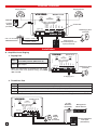
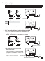
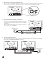
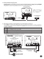
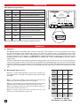
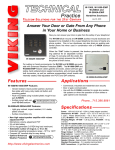
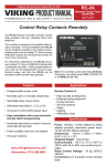
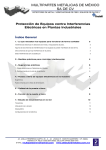
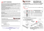
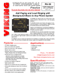
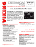
Designed, Manufactured and Supported in the USA
PA-2A
VIKING PRODUCT MANUAL
Paging Amplifier
Loud Ringer
May 7, 2014
C O M M U N I C AT I O N & S E C U R I T Y S O L U T I O N S
Add Paging and Multiple Line
Loud Ringing to Any Phone System
The PA-2A provides loud ringing and paging
to electronic key systems, 1A2 Key systems,
PABX’s as well as No-KSU phones and multiline phones.
Paging is accomplished by connecting the
PA-2A to a paging port or unused telephone
line input (trunk port) of nearly any phone
system.
The PA-2A will also generate adjustable loud
ringing from up to 6 analog lines or from a dry
contact closure. Either a loud electronic warble, or one of three other soft chime sounds
may be selected. An external “night transfer”
switch can be added to turn loud ringing on
or off in night bell applications.
The PA-2A is easy to install and eliminates
the installation of multiple bells, relays and
paging cards.
Features
• Two watts of paging power
• Includes (1) Viking 25AE paging horn
• All lines are optically coupled for compatbility
with fax switches and analog PABX/KSU stations
• Can provide background music from an external source (trunk mode only)
• Paging from an unused trunk port or paging
port
• Choose one of four ringing sounds:
- Electronic warble (traditional loud ringer)
- Double gong (two identical “gong” tones)
- Quadruple chime (four descending chime tones)
- Door chime (ding-dong)
• Provides loud ringing or night bell, from 1-6
lines for warehouses, yards, etc.
• Output for controlling a 12 volt relay from 1-6
ringing lines
• Page alert tone (trunk mode only)
• 600 ohm output for sourcing high powered amplifiers
The unit comes complete
with a power supply, amplifier and (1) Viking
25AE paging horn.
Applications
• Amplified loud paging
• Night bell
• Loud ringing
www.vikingelectronics.com
Information: (715) 386-8861
Specifications
Power: 120V AC/13.8V AC 1.25A, UL listed adapter provided
Dimensions: 133mm x 89mm x 44mm (5.25” x 3.5” x
1.75”)
Shipping Weight: 1.36 kg (3 lbs)
Environmental: 0°C to 32°C (32°F to 90°F) with 5% to
95% noncondensing humidity
Paging Output: 2 watts - powers up to (3) 8 ohm or (16)
45 ohm speakers
Sound Pressure: 108 dB, 1 kHz @ 1 meter with (1) 25AE
paging horn (included). See Page Power Chart for more
info, DOD# 895.
Speakers: (1) 25AE 8 ohm paging horn included, (3)
maximum
Maximum Speaker Run: See Speakers section, page 6
Talk Battery: 24V DC
Connections: (2) RJ25 jacks, (1) 10 position screw terminal block
Features Overview
Ringing Volume
Paging Volume
VIKING ©
MODEL PA-2A
PAGING
VOLUME
RINGING
VOLUME
MAX
POWER 13.8V AC
MIN
MAX
MIN
MIN
2 3 4
600 OHM
AUDIO OUT
NIGHT
TRANSFER
1
PAGING
HORN
1 2 34 5
Power LED
TRUNK OR
PAGING PORT
RINGING LINES
1-3
4-6
MAX
MAX
PAGING - LOUD RINGING
AMPLIFIER SYSTEM
WARBLE / CHIME
13.8V AC
Adapter
(included)
LOUD RING
TRIGGER INPUT
120V AC
VIKING
ELECTRONICS
HUDSON, WI 54016
ALERT TONE
TALK BATTERY
AUDIO LOADING
MIN
5 6
7 8
9 10
25AE Paging Horn
(included)
PWR
Lines 1, 2 and 3
C.O. Line or Analog
PABX/KSU Station
Paging Port or
Unused Telephone Line
Input (Trunk Port)
Lines 4, 5 and 6
Installation
A. Amplified Loud Paging
MIN
MAX
MIN
MAX
2 3 4
600 OHM
AUDIO OUT
1
PAGING
HORN
1 2 34 5
TRUNK OR
PAGING PORT
RINGING LINES
1-3
4-6
NIGHT
TRANSFER
PAGING - LOUD RINGING
AMPLIFIER SYSTEM
LOUD RING
TRIGGER INPUT
Connect pins 5 and 6 to the paging
port output.
RINGING
VOLUME
VIKING
ELECTRONICS
HUDSON, WI 54016
WARBLE / CHIME
Step 2
MODEL PA-2A
PAGING
VOLUME
ALERT TONE
TALK BATTERY
AUDIO LOADING
Move the TALK BATTERY DIP switch
Step 1
to the OFF position (DIP switch 4).
VIKING ©
POWER 13.8V AC
1. Paging Port
5 6
7 8
9 10
PWR
Note: For information on speakers to use, ambient noise levels, and speaker wiring, see DOD#
498 and 895.
25AE Paging Horn
(included)
To Paging Port
2. Trunk/Line Port
Step 1 Move the TALK BATTERY DIP switch to the ON position (DIP switch 4).
Step 2 Move the AUDIO LOADING switch to the OFF position (DIP switch 5).
Step 3 Connect pins 5 and 6 to an unused telephone line input (trunk port).
Step 4 Background music may be added as shown, the music level will be greatly reduced during page.
Note: For information on speakers to use, ambient noise levels, and speaker wiring, see DOD# 498 and 895.
MODEL PA-2A
PAGING
VOLUME
RINGING
VOLUME
MIN
VIKING
ELECTRONICS
HUDSON, WI 54016
MAX
MIN
(2) 10K
Resistors
(included)
MAX
2 3 4
600 OHM
AUDIO OUT
NIGHT
TRANSFER
1
PAGING
HORN
1 2 34 5
TRUNK OR
PAGING PORT
RINGING LINES
1-3
4-6
LOUD RING
TRIGGER INPUT
WARBLE / CHIME
PAGING - LOUD RINGING
AMPLIFIER SYSTEM
ALERT TONE
TALK BATTERY
AUDIO LOADING
POWER 13.8V AC
VIKING ©
5 6
7 8
9 10
Background
Music Source
PWR
25AE
Paging
Horn
(included)
2
Unused Telephone
Line Input
(Trunk Port)
B. Loud Ringing / Night Bell
1. Ringing Analog Lines
Step 1 Connect lines 1 (R/G), 2 (Y/BK) and 3 (BL/W) to RINGING LINES 1-3.
Step 2 Connect lines 4 (R/G), 5 (Y/BK) and 6 (BL/W) to RINGING LINES 4-6.
Note: For information on speakers to use, ambient noise levels, and speaker wiring, see DOD# 498 and 895.
Ringing Line Input Wiring
MIN
RINGING
VOLUME
MAX
MIN
MAX
1
2 3 4
600 OHM
AUDIO OUT
1 2 34 5
TRUNK OR
PAGING PORT
RINGING LINES
1-3
4-6
Line 4
PAGING
HORN
WARBLE / CHIME
PAGING - LOUD RINGING
AMPLIFIER SYSTEM
5 6
7 8
9 10
25AE Paging Horn
(included)
PWR
Yellow
Line 2
Blue
White
Red
MODEL PA-2A
VIKING
ELECTRONICS
HUDSON, WI 54016
LOUD RING
TRIGGER INPUT
Green
Line 1
Yellow
Black
POWER 13.8V AC
RJ25
Green
Red
PAGING
VOLUME
ALERT TONE
TALK BATTERY
AUDIO LOADING
RJ25
VIKING ©
Lines 4-6
NIGHT
TRANSFER
Lines 1-3
Black
Line 5
Blue
Line 3
White
Line 6
Lines 4, 5 and 6
Lines 1, 2 and 3
2. Dry Contact (Common Audible) Closure (contacts not included)
VIKING ©
PAGING
VOLUME
RINGING
VOLUME
MAX
MIN
MAX
2 3 4
600 OHM
AUDIO OUT
1
PAGING
HORN
1 2 34 5
TRUNK OR
PAGING PORT
RINGING LINES
1-3
4-6
LOUD RING
TRIGGER INPUT
PAGING - LOUD RINGING
AMPLIFIER SYSTEM
WARBLE / CHIME
Note: For information on speakers to
use, ambient noise levels, and speaker
wiring, see DOD# 498 and 895.
MIN
ALERT TONE
TALK BATTERY
AUDIO LOADING
A dry contact closure will initiate
Step 2
loud ringing.
MODEL PA-2A
VIKING
ELECTRONICS
HUDSON, WI 54016
NIGHT
TRANSFER
Connect the dry contact closure
to pins 3 and 4.
POWER 13.8V AC
Step 1
5 6
7 8
9 10
PWR
25AE Paging Horn
(included)
Dry Contact Closure
(not included)
3. Night Transfer (Loud Ringing) Switch (switch not included)
A Night Transfer Switch may be used to enable or disable loud ringing.
a. Ringing Analog Lines
Connect the night transfer switch to terminal pins 1 and 2. When the switch is on (closed), loud ringing is
disabled. When the switch is off (open), loud ringing is enabled.
Ringing Line Input Wiring
MAX
RINGING
VOLUME
MIN
MAX
2 3 4
PAGING
HORN
1
600 OHM
AUDIO OUT
1 2 34 5
Line 4
TRUNK OR
PAGING PORT
RINGING LINES
1-3
4-6
LOUD RING
TRIGGER INPUT
PAGING - LOUD RINGING
AMPLIFIER SYSTEM
5 6
7 8
9 10
PWR
25AE Paging Horn
(included)
Yellow
Line 2
Blue
White
Red
MIN
MODEL PA-2A
VIKING
ELECTRONICS
HUDSON, WI 54016
WARBLE / CHIME
Green
Line 1
Yellow
Black
POWER 13.8V AC
RJ25
Green
Red
PAGING
VOLUME
ALERT TONE
TALK BATTERY
AUDIO LOADING
RJ25
VIKING ©
Lines 4-6
NIGHT
TRANSFER
Lines 1-3
Black
Line 5
Blue
Line 3
White
Line 6
Lines 4, 5 and 6
Lines 1, 2 and 3
Night Transfer (Loud Ringing) Switch
(not included) Use Viking model
NS-1 (DOD#540)
Note: For information on speakers to use, ambient noise levels, and speaker wiring, see DOD# 498 and 895.
VIKING ©
MIN
MAX
RINGING
VOLUME
MIN
MAX
1
2 3 4
PAGING
HORN
1 2 34 5
600 OHM
AUDIO OUT
RINGING LINES
1-3
4-6
TRUNK OR
PAGING PORT
WARBLE / CHIME
PAGING - LOUD RINGING
AMPLIFIER SYSTEM
ALERT TONE
TALK BATTERY
AUDIO LOADING
Interface the night transfer switch in series with the
contact closure. When the switch is on (closed),
loud ringing is enabled. When the switch is off
(open), loud ringing is disabled.
MODEL PA-2A
VIKING
ELECTRONICS
HUDSON, WI 54016
NIGHT
TRANSFER
POWER 13.8V AC
PAGING
VOLUME
LOUD RING
TRIGGER INPUT
b. Dry Contact Closure with Night Transfer
(Loud Ringing) Switch
5 6
7 8
9 10
PWR
25AE Paging Horn
(included)
Note: For information on speakers to
use, ambient noise levels, and speaker
wiring, see DOD# 498 and 895.
Dry Contact Closure
(not included)
Night Transfer (Loud Ringing) Switch
(not included)
3
C. Contact Closure From Up to 6 Ringing Lines
When a 12V DC relay coil (Radio Shack part: # 275-042, not included) is connected as shown in the diagram
below, the relay is activated for the duration of each ring on 1-6 C.O. lines or analog PABX/KSU stations.
MODEL PA-2A
PAGING
VOLUME
RINGING
VOLUME
POWER 13.8V AC
VIKING ©
MIN
VIKING
ELECTRONICS
HUDSON, WI 54016
MAX
MIN
RELAY
CONTROL
N.O.
MAX
2 3 4
600 OHM
AUDIO OUT
LOUD RING
TRIGGER INPUT
NIGHT
TRANSFER
1
PAGING
HORN
1 2 34 5
N.C.
TRUNK OR
PAGING PORT
RINGING LINES
1-3
4-6
ALERT TONE
TALK BATTERY
AUDIO LOADING
WARBLE / CHIME
PAGING - LOUD RINGING
AMPLIFIER SYSTEM
5 6
7 8
9 10
COM
Relay (Radio Shack
Part # 275-042)
PWR
D. Long Runs Between Amplifier and Speakers
VIKING ©
MODEL PA-2A
PAGING
VOLUME
RINGING
VOLUME
POWER 13.8V AC
MIN
MAX
MIN
MAX
2 3 4
600 OHM
AUDIO OUT
NIGHT
TRANSFER
1
PAGING
HORN
1 2 34 5
TRUNK OR
PAGING PORT
RINGING LINES
1-3
4-6
LOUD RING
TRIGGER INPUT
PAGING - LOUD RINGING
AMPLIFIER SYSTEM
WARBLE / CHIME
Note: For additional information on how to minimize loss of audio
in long speaker runs, see DOD# 856.
VIKING
ELECTRONICS
HUDSON, WI 54016
ALERT TONE
TALK BATTERY
AUDIO LOADING
Very long runs between the PA-2A and the speakers might require
70V transformers (Parts Express 1-800-338-0531, part # 300-040
or equivalent).
5 6
7 8
9 10
PWR
25AE Paging Horn
(included)
8 Ohm
Com
2.5 Watt
(Very Long Run)
Com
2.5 Watt
Com
8 Ohm
Com
Parts Express part # 300-040
1-800-338-0531
E. Connecting Multiple PA-2A’s
When more than 6 ringing lines are to be monitored or additional amplifiers need to be added, install as shown
below, using the 600 OHM AUDIO OUTPUT connections.
VIKING ©
MODEL PA-2A
RINGING
VOLUME
PAGING
VOLUME
RINGING
VOLUME
9 10
MAX
RINGING LINES
1-3
4-6
PWR
1 2 34 5
1
2 3 4
600 OHM
AUDIO OUT
7 8
MIN
PAGING - LOUD RINGING
AMPLIFIER SYSTEM
PAGING
HORN
5 6
MAX
TRUNK OR
PAGING PORT
PAGING
HORN
LOUD RING
TRIGGER INPUT
2 3 4
600 OHM
AUDIO OUT
1
TRUNK OR
PAGING PORT
1 2 34 5
NIGHT
TRANSFER
ALERT TONE
TALK BATTERY
AUDIO LOADING
WARBLE / CHIME
RINGING LINES
1-3
4-6
MIN
NIGHT
TRANSFER
MAX
LOUD RING
TRIGGER INPUT
MIN
PAGING - LOUD RINGING
AMPLIFIER SYSTEM
WARBLE / CHIME
MAX
VIKING
ELECTRONICS
HUDSON, WI 54016
ALERT TONE
TALK BATTERY
AUDIO LOADING
MIN
VIKING
ELECTRONICS
HUDSON, WI 54016
POWER 13.8V AC
MODEL PA-2A
PAGING
VOLUME
POWER 13.8V AC
VIKING ©
5 6
7 8
9 10
PWR
25AE Paging Horn
(included)
Note: DIP switch 4 must
be in the OFF position.
4
F. Adding Additional Paging Power
An external amplifier can be added to increase the paging and loud ringing power. Simply connect the 600 OHM
AUDIO OUTPUT screw terminals to the line level input of any high powered paging amplifier, such as the 30 Watt
Viking PA-30, the 60 Watt Viking PA-60 (not shown), or any existing paging system.
PA-30 Paging Amplifier
see DOD# 489 (not included)
VIKING ©
MODEL PA-30
MASTER
VOLUME
VIKING
ELECTRONICS
HUDSON, WI 54016
PWR 15 VAC
TPG
MIN
5
6
7 8
CONTACT
CLOSURE
NIGHT
TRANSFER
LINE IN
9 10 11 12 13 14 15 16 17
LED3
LED4
C
LED5
C
C
on
600 OHM
AUDIO OUT
PAGING
HORN
C
TRUNK OR
PAGING PORT
2 3 4
PAGE
CONTACT
PAGE IN
AUX IN
600 OHM
OUTPUT
4
LED2
LOUD RING
TRIGGER INPUT
WARBLE / CHIME
ALERT TONE
TALK BATTERY
AUDIO LOADING
NIGHT
TRANSFER
1
1 2 34 5
3
MAX
MIN
PAGING - LOUD RINGING
AMPLIFIER SYSTEM
RINGING LINES
1-3
4-6
2
C
MAX
BACKGROUND
MUSIC IN
1
SPKRS
RINGING
VOLUME
VIKING
ELECTRONICS
HUDSON, WI 54016
SPKRS
PAGING
VOLUME
POWER 13.8V AC
MODEL PA-2A
* Note: For information on
speakers to use, ambient
noise levels and speaker
wiring, see DOD# 498.
MAX
LOUD RINGING
70V OUT
VIKING ©
MIN
30 WATT TELECOM
PAGING AMPLIFIER
5 6
7 8
9 10
1
LED
1
2
3
4
Existing Paging Amplifier
(not included)
* Up to (30)
8 Ohm Speakers
(not included)
PWR
or
G. Add Paging to Homes and Small Businesses with Single Line Phones
The C-1000B can be added to allow PA-2A paging from the existing single line phones. If need be, a doorbox or
a second paging amplifier may also be added to the C-1000B Doorbox 2 Terminals. For more information on the
C-1000B, see DOD# 168.
Step 1 Program the C-1000B to be in the Paging Mode Q4.
Step 2 Set the C-1000B Talk Battery switch OFF.
Step 3 Connect the PA-2A Trunk Port (pins 5 & 6) to the C-1000B Door Box 1 terminals.
Step 4 Move the PA-2A Talk Battery switch ON (DIP switch 4).
Step 5 To page, come off hook on the phone and dial #1.
C-1000B Door Entry/Paging Controller (not included)
RINGING LINES
1-3
4-6
1 2 34 5
NIGHT
TRANSFER
POWER 13.8V AC
DOOR
STRIKE 2
N.C.
COM
N.O.
DOOR
STRIKE 1
MAX
1
2 3 4
5 6
7 8
9 10
PWR
ON
C
LED1
OUT TO
PHONES
N.C.
9 10 11 12 13 14 15 16 17 18 19
MIN
PAGING - LOUD RINGING
AMPLIFIER SYSTEM
N.O. N.C. - - - - AUX.
CONTACT
OUTPUT
SIG GND SIG GND SIG GND
VIDEO 1 IN VIDEO 2 IN VIDEO OUT
EARTH C.O. LINE
GND
INPUT
COM
N.O.
DOORBOX 2
DOORBOX
PWR OUTPUT
DOORBOX 1
KEYLESS CONTACT
CLOSURE INPUT
6 7 8
MAX
600 OHM
AUDIO OUT
4 5
COM
MIN
PAGING
HORN
3
LINE OUT
TO PHONES
PHONE LINE
INPUT
2
RINGING
VOLUME
VIKING
ELECTRONICS
HUDSON, WI 54016
TRUNK OR
PAGING PORT
1
MODEL PA-2A
PAGING
VOLUME
LOUD RING
TRIGGER INPUT
POWER 13.8V AC
EARTH
GND
DOOR ENTRY / CCTV VIDEO
CONTROLLER
VIKING ©
WARBLE / CHIME
MODEL C-1000B
VIKING
ELECTRONICS
HUDSON, WI 54016
ALERT TONE
TALK BATTERY
AUDIO LOADING
VIKING ©
KEYLESS
C.C. INPUT
TALK
OFF
DOOR
BOX 1
DOORBOX
13VAC PWR
BATTERY
ON
DOOR
BOX 2
1
C
LED2
N.O. COM N.C.
DOOR STRIKE 1
2
3
C
LED3
N.O. COM N.C.
DOOR STRIKE 2
Standard
Analog Phones
25AE Paging Horn
(included)
C.O. Line or Analog
PABX/KSU station
5
Programming
DIP Switch Programming
ON
OFF
Quadruple Chime (Soft & Pleasant)
ON
ON
Door Chime (Soft & Pleasant)
Switch
Position
3
OFF
Alert tone OFF (factory default)
3
ON
Alert tone ON
4
OFF
Talk battery OFF (factory default)
4
ON
Talk battery ON
5
OFF
Audio load 10K (for applications using
background music)
RINGING
VOLUME
MIN
MAX
RINGING LINES
1-3
4-6
Description
MIN
MAX
PAGING - LOUD RINGING
AMPLIFIER SYSTEM
1 2 34 5
1
2 3 4
600 OHM
AUDIO OUT
Double Gong (Soft & Pleasant)
VIKING
ELECTRONICS
HUDSON, WI 54016
PAGING
HORN
ON
MODEL PA-2A
PAGING
VOLUME
TRUNK OR
PAGING PORT
OFF
VIKING ©
NIGHT
TRANSFER
Electronic Warble (Loudest Sound)
LOUD RING
TRIGGER INPUT
Sound Output Description
WARBLE / CHIME
OFF
ALERT TONE
TALK BATTERY
AUDIO LOADING
Switch 2
OFF
POWER 13.8V AC
Switch 1
5 6
7 8
9 10
ON
OFF
5
ON
Audio load 600 ohms (factory default)
1 2 3 4 5
Note: DIP Switches are shown in factory default positions.
Speakers
A. Speakers
The PA-2A contains an amplifier which can drive up to three 8-ohm speakers. The more speakers that are used,
the less shared power each speaker will receive, the softer they will each play. A single speaker with a short
speaker wire run will receive the full 2 watts of power, where if 3 speakers are used, there will be less then 1 watt
of power available for each speaker. See DOD# 895 for additional information on paging horn volume per number
of speakers being used. If additional paging power is needed, add a Viking model PA-60 for 60 more watts of
paging power.
Another consideration when budgeting speakers is paging power that is lost in the wire runs. A single speaker on
a short heavy gauge wire will have no loss, but many speakers on a long light gauge wire will have an unacceptable
amount of volume lost. Use the below chart as a guide line to keep the volume lost limited to less then 5db. Using
half the recommended distance or half as many speakers per run will keep the volume lost limited to less then
3db.
B. Managing Power Losses
Note 1: Mount the amplifier close to where the speakers are
installed to minimize the speaker wire run lengths.
Note 2: Using half the recommended distance or half as many
speakers per run will keep the volume lost limited to 3db.
Note 3: Doubling up the wires will allow double the length, or
reduce the amount of volume loss.
Note 4: Heavier gauge wire, fewer speakers per run, and
shorter runs will all minimize volume loss.
6
Wire Gauge Size
Maximum recommended length (in feet) for the number of 8
Ohm speakers on a wire pair to maintain a volume loss of less
than 5dB.
#16
2,000' 1,000'
665'
#18
1,250'
625'
420'
#20
800'
400'
265'
#22
500'
250'
165'
#24
315'
155'
105'
1
2
3
Number of 8 Ohm
Speakers on a Wire Run
Sound Output Specifications
All tones require a minimum of 180ms of ringing voltage (or contact closure) to trigger. Once triggered, the electronic
warble will run continuously until ringing stops (or contacts open). All other tones (double gong, quadruple chime,
doorbell) will run through their full sequence once and will not cycle again until the ringing stops (or contact opens) for
at least 50ms and a second ring signal (or contact closure) triggers them again.
A. Electronic Warble (Traditional Loud Ringer)
2 seconds
On
Frequency alternates between 1440 Hz and
1140 Hz 20 times per second.
Off
B. Double Gong (Two “Gong” Tones)
0.74
sec
2.2 sec
On
Off
575 Hz
575 Hz
C. Quadruple Chime (Four Descending Chime Tones)
On
0.36
sec
0.36
sec
0.36
sec
888 Hz
699 Hz
584 Hz
2.2 sec
492 Hz
Off
D. Door Chime (Ding-Dong)
0.36
sec
2.7
sec
On
Off
794 Hz
526 Hz
Operation
When interfacing the PA-2A to a paging port, the TALK BATTERY switch (DIP switch 4) must be OFF. The PA-2A
will amplify all signals sent from the paging port. The page alert tone (DIP switch 3) is not an available option.
When interfacing with an unused telephone line input (trunk port), the TALK BATTERY switch (DIP switch 4) must be
ON and the PA-2A must be connected to an unused trunk port. Simply access that trunk port and talk into the handset
to page. A page alert tone may be enabled or disabled with DIP switch 3. When the page alert tone is enabled, paging
will interrupt and hold off loud ringing for the duration of the page.
In both instances, the PA-2A can monitor 1 - 6 C.O. lines, 1 - 6 analog PABX/KSU stations or a dry contact closure
for loud ringing. The PA-2A will produce the selected ringing tone when ring voltage is detected on these line inputs
or a contact is closed on pins 3 and 4. Select the electronic warble tone (traditional loud ringing) for noisy areas. The
softer chime tones work well in less noisy environments.
7
Warranty
IF YOU HAVE A PROBLEM WITH A VIKING PRODUCT, CONTACT: VIKING TECHNICAL SUPPORT AT (715) 386-8666
Our Technical Support Department is available for assistance Monday 8am - 4pm and Tuesday through Friday 8am - 5pm central time. So that we can give you better service, before you call please:
1. Know the model number, the serial number and what software version you have (see serial label).
2. Have your Technical Practice in front of you.
3. It is best if you are on site.
RETURNING PRODUCT FOR REPAIR
The following procedure is for equipment that needs repair:
1. Customer must contact Viking's Technical Support Department at 715-386-8666 to obtain a Return Authorization (RA) number. The customer MUST have a complete description of the problem,
with all pertinent information regarding the defect, such as options set, conditions, symptoms, methods to duplicate problem, frequency of failure, etc.
2. Packing: Return equipment in original box or in proper packing so that damage will not occur while in transit. Static sensitive equipment such as a circuit board should be in an anti-static bag,
sandwiched between foam and individually boxed. All equipment should be wrapped to avoid packing material lodging in or sticking to the equipment. Include ALL parts of the equipment. C.O.D. or
freight collect shipments cannot be accepted. Ship cartons prepaid to: Viking Electronics, 1531 Industrial Street, Hudson, WI 54016
3. Return shipping address: Be sure to include your return shipping address inside the box. We cannot ship to a PO Box.
4. RA number on carton: In large printing, write the R.A. number on the outside of each carton being returned.
RETURNING PRODUCT FOR EXCHANGE
The following procedure is for equipment that has failed out-of-box (within 10 days of purchase):
1. Customer must contact Viking’s Technical Support at 715-386-8666 to determine possible causes for the problem. The customer MUST be able to step through recommended tests for diagnosis.
2. If the Technical Support Product Specialist determines that the equipment is defective based on the customer's input and troubleshooting, a Return Authorization (R.A.) number will be issued.
This number is valid for fourteen (14) calendar days from the date of issue.
3. After obtaining the R.A. number, return the approved equipment to your distributor, referencing the R.A. number. Your distributor will then replace the Viking product using the same R.A. number.
4. The distributor will NOT exchange this product without first obtaining the R.A. number from you. If you haven't followed the steps listed in 1, 2 and 3, be aware that you will have to
pay a restocking charge.
TWO YEAR LIMITED WARRANTY
Viking warrants its products to be free from defects in the workmanship or materials, under normal use and service, for a period of two
years from the date of purchase from any authorized Viking distributor. If at any time during the warranty period, the product is deemed
defective or malfunctions, return the product to Viking Electronics, Inc., 1531 Industrial Street, Hudson, WI., 54016. Customer must contact
Viking's Technical Support Department at 715-386-8666 to obtain a Return Authorization (R.A.) number.
This warranty does not cover any damage to the product due to lightning, over voltage, under voltage, accident, misuse, abuse, negligence
or any damage caused by use of the product by the purchaser or others. This warranty does not cover non-EWP products that have been
exposed to wet or corrosive environments. This warranty does not cover stainless steel surfaces that have not been properly maintained.
NO OTHER WARRANTIES. VIKING MAKES NO WARRANTIES RELATING TO ITS PRODUCTS OTHER THAN AS DESCRIBED ABOVE
AND DISCLAIMS ANY EXPRESS OR IMPLIED WARRANTIES OR MERCHANTABILITY OR FITNESS FOR ANY PARTICULAR PURPOSE.
EXCLUSION OF CONSEQUENTIAL DAMAGES. VIKING SHALL NOT, UNDER ANY CIRCUMSTANCES, BE LIABLE TO PURCHASER,
OR ANY OTHER PARTY, FOR CONSEQUENTIAL, INCIDENTAL, SPECIAL OR EXEMPLARY DAMAGES ARISING OUT OF OR RELATED
TO THE SALE OR USE OF THE PRODUCT SOLD HEREUNDER.
EXCLUSIVE REMEDY AND LIMITATION OF LIABILITY. WHETHER IN AN ACTION BASED ON CONTRACT, TORT (INCLUDING NEGLIGENCE OR STRICT LIABILITY) OR ANY OTHER LEGAL THEORY, ANY LIABILITY OF VIKING SHALL BE LIMITED TO REPAIR OR REPLACEMENT OF THE PRODUCT, OR AT VIKING'S OPTION, REFUND OF THE PURCHASE PRICE AS THE EXCLUSIVE REMEDY AND
ANY LIABILITY OF VIKING SHALL BE SO LIMITED.
IT IS EXPRESSLY UNDERSTOOD AND AGREED THAT EACH AND EVERY PROVISION OF THIS AGREEMENT WHICH PROVIDES
FOR DISCLAIMER OF WARRANTIES, EXCLUSION OF CONSEQUENTIAL DAMAGES, AND EXCLUSIVE REMEDY AND LIMITATION OF
LIABILITY, ARE SEVERABLE FROM ANY OTHER PROVISION AND EACH PROVISION IS A SEPARABLE AND INDEPENDENT ELEMENT
OF RISK ALLOCATION AND IS INTENDED TO BE ENFORCED AS SUCH.
FCC REQUIREMENTS
This equipment complies with Part 68 of the FCC rules and the requirements adopted by the ACTA.
On the side of this equipment is a label that contains, among other information, a product identifier in
the format US:AAAEQ##TXXXX. If requested, this number must be provided to the telephone company.
The REN is used to determine the number of devices that may be connected to a telephone line. Excessive REN's on a telephone line may result in the devices not ringing in response to an incoming
call. In most but not all areas, the sum of the REN's should not exceed five (5.0) To be certain of the
number of devices that may be connected to a line, as determined by the total REN's, contact the
local telephone company. For products approved after July 23, 2001, the REN for this product is part
of the product identifier that has the format US:AAAEQ##TXXXX. The digits represented by ## are
the REN without a decimal point (e.g., 03 is a REN of 0.3). For earlier products, the REN is separately
shown on the label.
The plug used to connect this equipment to the premises wiring and telephone network must comply
with the applicable FCC Part 68 rules and requirements adopted by the ACTA. If your home has specially wired alarm equipment connected to the telephone line, ensure the installation of this PA-2A
does not disable your alarm equipment. If you have questions about what will disable alarm equipment,
consult your telephone company or a qualified installer.
If the PA-2A causes harm to the telephone network, the telephone company will notify you in advance
that temporary discontinuance of service may be required. But if advance notice isn't practical, the
telephone company will notify the customer as soon as possible. Also, you will be advised of your right
to file a complaint with the FCC if you believe it is necessary.
The telephone company may make changes in its facilities, equipment, operations, or procedures that
could affect the operation of the equipment. If this happens, the telephone company will provide advance notice in order for you to make the necessary modifications to maintain uninterrupted service.
If trouble is experienced with the PA-2A, for repair or warranty information, please contact:
Viking Electronics, Inc., 1531 Industrial Street, Hudson, WI 54016 (715) 386-8666
If the equipment is causing harm to the telephone network, the telephone company may request
that you disconnect the equipment until the problem is resolved.
Connection to Party Line Service is subject to State Tariffs. Contact the state public utility commission, public service commission or corporation commission for information.
WHEN PROGRAMMING EMERGENCY NUMBERS AND (OR) MAKING TEST CALLS TO
EMERGENCY NUMBERS:
Remain on the line and briefly explain to the dispatcher the reason for the call. Perform such
activities in the off-peak hours, such as early morning or late evenings.
It is recommended that the customer install an AC surge arrester in the AC outlet to which this
device is connected. This is to avoid damaging the equipment caused by local lightning strikes
and other electrical surges.
PART 15 LIMITATIONS
This equipment has been tested and found to comply with the limits for a Class A digital
device, pursuant to Part 15 of the FCC Rules. These limits are designed to provide
reasonable protection against harmful interference when the equipment is operated in
a commercial environment. This equipment generates, uses, and can radiate radio frequency energy and, if not installed and used in accordance with the instruction manual,
may cause harmful interference to radio communications. Operation of this equipment
in a residential area is likely to cause harmful interference in which case the user will
be required to correct the interference at his own expense.
Product Support: (715) 386-8666
Due to the dynamic nature of the product design, the information contained in this document is subject to change without notice. Viking Electronics, and its affiliates
and/or subsidiaries assume no responsibility for errors and omissions contained in this information. Revisions of this document or new editions of it may be issued
to incorporate such changes.
8
DOD# 485
Printed in the U.S.A.
ZF301730 Rev E