1
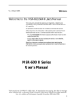
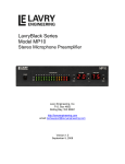
USER GUIDE Publication AP8769 Limited One Year Warranty This product is warranted to be free from defects in materials or workmanship for period of one year from the date of purchase by the original owner. To ensure a high level of performance and reliability for which this equipment has been designed and manufactured, read this User Guide before operating. In the event of a failure, notify and return the defective unit to ALLEN & HEATH Limited or its authorised agent as soon as possible for repair under warranty subject to the following conditions Conditions Of Warranty The equipment has been installed and operated in accordance with the instructions in this User Guide. The equipment has not been subject to misuse either intended or accidental, neglect, or alteration other than as described in the User Guide or Service Manual, or approved by ALLEN & HEATH. Any necessary adjustment, alteration or repair has been carried out by ALLEN & HEATH or its authorised agent. This warranty does not cover fader wear and tear. The defective unit is to be returned carriage prepaid to ALLEN & HEATH or its authorised agent with proof of purchase. Units returned should be packed to avoid transit damage. In certain territories the terms may vary. Check with your ALLEN & HEATH agent for any additional warranty which may apply. This product complies with the European Electromagnetic Compatibility directive 2004/108/EC and the European Low Voltage directive 2006/95/EC. This product has been tested to EN55103 Parts 1 & 2 2009 for use in Environments E1, E2, E3, and E4 to demonstrate compliance with the protection requirements in the European EMC directive 2004/108/EC. During some tests the specified performance figures of the product were affected. This is considered permissible and the product has been passed as acceptable for its intended use. Allen & Heath has a strict policy of ensuring all products are tested to the latest safety and EMC standards. Customers requiring more information about EMC and safety issues can contact Allen & Heath. NOTE: Any changes or modifications to the console not approved by Allen & Heath could void the compliance of the console and therefore the users authority to operate it. Allen & Heath XB-14 MK2 User Guide AP8769 Issue 2 Copyright © 2012 Allen & Heath Limited. All rights reserved Allen & Heath Limited Kernick Industrial Estate, Penryn, Cornwall, TR10 9LU, UK http://www.allen-heath.com Allen & Heath 3 XB-14 MK2 User Guide PACKED ITEMS Check that you have received the following: MIC MIC LINE MIC LINE TEL IN MIC LINE LINE ST2 TEL IN CLF OUT CLF OUT TELCO 1 TELCO 2 MIX B OUT ST4 CRM SPEAKERS L L L L R R R R L/M L/M L/M L/M AUD OUT INSERT L L L R MAIN PGM OUT INSERT R EXT MON IN R L AUX M2 M3 M4 INSERT INSERT INSERT ST1 ST3 ST5 ST7 R R R GUEST PHONES 1 M2 0 20 3010 10 GAIN 0 MIC LINE 63 26 M3 0 20 3010 10 GAIN 40 50 -10 -6 0 MIC LINE 63 26 M4 0 20 3010 10 GAIN 40 50 -10 -6 100Hz 0 MIC LINE 63 26 T1 0 20 3010 10 GAIN 40 50 -10 -6 100Hz 0 MIC LINE T2 5 0 GAIN 40 10 -5 HF 12kHz HF 12kHz -15 500 63 26 1k 500 2k 1k 20 26 -1O 1k 2k 120Hz ST1 20Hz 2k ST3 0 ST1 + 15 -15 + 15 -15 + 15 LPF 700Hz 20k -15 700Hz MF -15 + 15 -15 + 15 LF + 15 -15 + 15 PRE PRE CLF SCE PRE AUX 5 -15 + 15 -15 + 15 -15 + 15 + 15 L HF 12kHz -15 + 15 -15 + 15 12kHz -15 + 15 -15 + 15 LF LF 80Hz 80Hz + 15 -15 + 15 AUD 80Hz AUX PRE AUX PRE AUX PRE AUX PRE AUX EXT MON PRE AUX USB IN AUX CRM+ PHONES SELECTION +6 OO +6 OO MIX B BUS = BAL GUEST PHONES SELECTION MIX B CRM SPEAKERS MIX B BUS = BAL +6 OO MIX B BUS = BAL +6 OO MIX B BUS = PAN +6 OO MIX B BUS = PAN +6 OO MIX B BUS = PAN +6 OO MIX B BUS = PAN +6 OO MIX B BUS = PAN +6 OO MIX B BUS = PAN +6 OO MIX B BUS = R PFL ACTIVE -15 LF 80Hz AUX PGM PRE AUX + 15 HF HF 12kHz + 16 +9 +6 +3 0VU -3 -6 -9 -12 -16 -20 -30 AUDITION CLF SCE PGM PRE AUX + 16 +9 +6 +3 0VU -3 -6 -9 -12 -16 -20 -30 ON MIX B TALK LF 80Hz AUX AUX POWER 48V 0 ST7 5 -15 + 15 HF -15 LF 80Hz AUDITION PGM MIX 0 ST5 5 -15 20k AUDITION LF 80Hz 0 ST3 12kHz + 15 -15 ST5 AUX+ MONO 3k 4k TALK -15 LF 80Hz 5/USB 6kHz 3k LPF SEND RETURN + 15 ST6 (USB) 3/4 5 120Hz 4k MF 6kHz 3k GUEST PHONES 2 CRM PHONES USB 5 -15 + 15 ST4 1/2 HPF 20Hz 1k 0 5 -15 + 15 ST2 + 15 650 200 3k 4k MF 500 ST6 0 5 -15 26 120Hz HPF -15 + 15 650 200 3k 120Hz 4k MF 500 2k 3k 120Hz 12kHz -15 + 15 650 200 ST4 0 10 -5 -1O 100Hz HF 12kHz -15 + 15 650 200 ST2 5 0 GAIN 20 50 -10 -6 100Hz 120Hz HF USB SOURCE SELECT M1 MONO OUT R R PFL ENABLE TO GUEST MIN MAX BAL TALK TO GUEST DIM SPKS L R L AUD R L AUD R L AUD R L AUD R L AUD R L AUD REM MUTE REM MUTE REM MUTE REM MUTE REM MUTE REM MUTE PEAK PEAK PEAK PEAK PEAK PEAK R L AUD SIGNAL PFL SIGNAL PFL SIGNAL PFL SIGNAL PFL PEAK SIGNAL PFL R L AUD R L AUD CUT SPKS R MIC FADER UP = CUT SPKS AUD GUEST PHONES CRM PHONES + START/CUE SIGNAL + START/CUE + START/CUE + START/CUE PEAK PEAK PEAK SIGNAL SIGNAL PFL PFL SIGNAL PFL MIN MAX MIN MAX MIN MAX MIN MAX SIGNAL PFL MIN PFL MAX EX MON AUD PGM MIX FADER PGM FDR PGM FDR PGM FDR PGM FDR PGM FDR PGM FDR PGM FDR PGM FDR 0 0 0 0 0 0 0 0 0 0 0 5 5 5 5 5 5 5 5 5 5 5 10 10 10 10 10 10 10 10 10 10 10 15 15 15 15 15 15 15 15 15 15 15 20 20 20 20 20 20 20 20 20 20 20 30 30 30 30 30 30 30 30 30 30 30 40 40 40 40 40 40 40 40 40 50 50 50 50 50 50 50 50 50 50 OO OO OO OO OO OO OO OO OO OO M1 M2 M3 M4 40 PGM FDR MIX B LEV PGM FDR 40 ALLEN& HEATH M1 INSERT T1 T2 ST1 ST2 ST3 ST4 50 OO PGM XB-14 MK2 MIXER Mains Lead (or leads) Check that the correct mains plug is fitted. This User Guide Type A-B USB Lead To connect the XB-14 to your computer. Allen & Heath 4 XB-14 MK2 User Guide SAFETY INSTRUCTIONS WARNINGS - Read the following before proceeding : CAU TION ATTENTION: RISQUE DE CHOC ELECTRIQUE – NE PAS OUVRIR Read instructions: Retain these safety and operating instructions for future reference. Adhere to all warnings printed here and on the console. Follow the operating instructions printed in this User Guide. Do not remove cover: Operate the console with its covers correctly fitted. Power sources: Connect the console to a mains power unit only of the type described in this User Guide and marked on the rear panel. Use the power cord with sealed mains plug appropriate for your local mains supply as provided with the console. If the provided plug does not fit into your outlet consult your service agent for assistance. Power cord routing: Route the power cord so that it is not likely to be walked on, stretched or pinched by items placed upon or against it. Grounding: Do not defeat the grounding and polarisation means of the power cord plug. Do not remove or tamper with the ground connection in the power cord. ! WARNING: This equipment must be earthed. Water and moisture: To reduce the risk of fire or electric shock do not expose the console to rain or moisture or use it in damp or wet conditions. Do not place containers of liquids on it which might spill into any openings. Ventilation: Do not obstruct the ventilation slots or position the console where the air flow required for ventilation is impeded. If the console is to be operated in a rack unit or flightcase ensure that it is constructed to allow adequate ventilation. Heat and vibration: Do not locate the console in a place subject to excessive heat or direct sunlight as this could be a fire hazard. Locate the console away from any equipment which produces heat or causes excessive vibration. Servicing: Switch off the equipment and unplug the power cord immediately if it is exposed to moisture, spilled liquid, objects fallen into the openings, the power cord or plug become damaged, during lightening storms, or if smoke, odour or noise is noticed. Refer servicing to qualified technical personnel only. Installation: Install the console in accordance with the instructions printed in this User Guide. Do not connect the output of power amplifiers directly to the console. Use audio connectors and plugs only for their intended purpose. Allen & Heath 5 XB-14 MK2 User Guide SAFETY INSTRUCTIONS Important Mains plug wiring instructions The console is supplied with a moulded mains plug fitted to the AC mains power lead. Follow the instructions below if the mains plug has to be replaced. The wires in the mains lead are coloured in accordance with the following code: TERMINAL ! WIRE COLOUR European USA/Canada L LIVE BROWN BLACK N NEUTRAL BLUE WHITE E EARTH GND GREEN & YELLOW GREEN The wire which is coloured Green and Yellow must be connected to the terminal in the plug which is marked with the letter E or with the Earth symbol. This appliance must be earthed. The wire which is coloured Blue must be connected to the terminal in the plug which is marked with the letter N. The wire which is coloured Brown must be connected to the terminal in the plug which is marked with the letter L. Ensure that these colour codes are followed carefully in the event of the plug being changed. General Precautions: Damage : Environment : Cleaning : Transporting : Hearing : Allen & Heath To prevent damage to the controls and cosmetics avoid placing heavy objects on the control surface, scratching the surface with sharp objects, or rough handling and vibration. Protect from excessive dirt, dust, heat and vibration when operating and storing. Avoid tobacco ash, smoke, drinks spillage, and exposure to rain and moisture. If the console becomes wet, switch off and remove mains power immediately. Allow to dry out thoroughly before using again. Avoid the use of chemicals, abrasives or solvents. The control panel is best cleaned with a soft brush and dry lint-free cloth. The faders, switches and potentiometers are lubricated for life. The use of electrical lubricants on these parts is not recommended. The fader and potentiometer knobs may be removed for cleaning with a warm soapy solution. Rinse and allow to dry fully before refitting them. The console may be transported as a free-standing unit or mounted in a rack or flightcase. Protect the controls from damage during transit. Use adequate packing if you need to ship the unit. To avoid damage to your hearing do not operate any sound system at excessively high volume. This applies particularly to close-to-ear monitoring such as headphones and in-ear systems. Continued exposure to high volume sound can cause frequency selective or wide range hearing loss. 6 XB-14 MK2 User Guide CONTENTS Thank you for purchasing your Allen & Heath XB-14 mixer. To ensure that you get the maximum benefit from the unit please spare a few minutes familiarizing yourself with the controls and setup procedures outlined in this user guide. For further information please refer to the additional information available on our web site, or contact our technical support team. http://www.allen-heath.com http://www.allen-heath.com/xb Warranty .............................................. Packed Items ........................................ Safety Instructions .............................. Contents ............................................... Panel Drawings .................................... Introduction to XB-14....................... Specifications ....................................... Dimensions .......................................... Block Diagram ..................................... Mono Input Channel .......................... TELCO Channels 1&2 ....................... Stereo Input Channel ST1 & ST2.... Stereo Input Channels ST3 & ST4 .. Master Section .................................... Remote Interface connectors .......... On Switch Options ............................ Remote Interface wiring ................... USB Connecting to a Computer .... Application Diagram—Self Op ........ Application Diagram—Studio .......... Tips– off-air recording ....................... Fixing into a Rack or furniture ........ General wiring notes ......................... Product Support ................................. Service Options .................................. Allen & Heath 7 3 4 5 7 8 9 11 13 14 15 18 21 23 24 27 28 29 30 31 32 33 34 35 36 37 XB-14 MK2 User Guide PANEL DRAWINGS This device complies with Part 15 of the FCC Rules. Operation is subject to the following two conditions: CAU TION (1) this device may not cause harmful interference, and (2) this device must accept any interference received, including interference that may cause undesired operation. RISK OF ELECTRIC SHOCK DO NOT OPEN ALLEN&HEATH AVIS: RISQUE DE CHOC ELECTRIQUE - NE PAS OUVRIR. CAUTION: FOR CONTINUED PROTECTION AGAINST RISK OF FIRE REPLACE FUSE WITH SAME TYPE AND RATING. ATTENTION: REMPLACER PAR UN FUSIBLE STRICTEMENT IDENTIQUE EN VALEURS. REFER SERVICING TO QUALIFIED SERVICE PERSONNEL. WARNING: THIS APPARATUS MUST BE EARTHED CET APPAREIL DOIT ETRE MIS A LA TERRE Laite on liitettävä suojamaadoituskoskettimilla varustettuun pistorasiaan Apparatet må tilkoples jordet stikkontakt Apparaten skall anslutas till jordat uttag FUSE T1.0A L 250V 20mm OFF ON 0 I SETUP OPTION SWITCHES (SEE USER MANUAL) AC MAINS IN ~ 100 - 240V~ 47-63Hz 30W EXT METER CONFORMS TO ANSI/UL STD. 60065-2003 CERTIFICATED TO CAN/CSA STD.60065-03 REMOTE A Serial No. ENGINEERED IN ENGLAND BY ALLEN & HEATH LIMITED. MIC REMOTE B MADE IN CHINA MIC MIC TEL IN MIC ST2 TEL IN CLF OUT LINE LINE LINE LINE M1 M2 M3 M4 INSERT INSERT INSERT INSERT MIX B OUT ST4 L L CRM SPEAKERS L R R R R L/M L/M L/M L/M CLF OUT AUD OUT INSERT L L L R L MAIN PGM OUT INSERT R EXT MON IN R L AUX ST1 ST3 ST5 ST7 MONO OUT R TELCO 1 R TELCO 2 R R R 5 SEND GUEST PHONES 1 GUEST PHONES 2 CRM PHONES 0 20 10 M2 10 30 GAIN 0 MIC LINE -10 -6 0 20 10 40 0 50 MIC LINE 63 26 M3 10 30 GAIN -10 -6 40 50 MIC LINE 63 26 100Hz 0 20 10 0 M4 10 30 GAIN -10 -6 40 50 MIC LINE 63 26 100Hz 0 20 10 0 T1 10 30 40 T2 5 0 GAIN 10 -5 20 63 26 100Hz -1O 20 -1O 26 HF HF HF HF 12kHz 12kHz 12kHz + 15 -15 500 650 + 15 -15 1k 500 200 2k 650 500 2k 3k 120Hz 650 120Hz + 15 650 6kHz 20Hz 3k + 15 -15 + 15 -15 + 15 LF LF 80Hz 80Hz + 15 PRE -15 + 15 PRE 20k POWER AUX+ MONO AUDITION 48V 0 ST7 5 -15 5 + 15 -15 CLF SCE AUX AUX PGM PGM PRE AUX + 15 HF HF 12kHz 12kHz 12kHz 12kHz + 15 + 15 -15 + 15 LF LF LF LF 80Hz 80Hz 80Hz 80Hz -15 + 15 PRE AUX -15 L + 15 -15 + 15 AUD -15 + 15 PRE AUX -15 + 15 PRE AUX AUX PRE AUX EXT MON PRE AUX USB IN AUX CRM+ PHONES SELECTION +6 OO +6 OO MIX B BUS = CRM PFL ENABLE TO GUEST MIN = BAL GUEST PHONES SELECTION MIX B SPEAKERS MIX B BUS = BAL +6 OO MIX B BUS = BAL +6 OO MIX B BUS = PAN +6 OO MIX B BUS = PAN +6 OO MIX B BUS = PAN +6 OO MIX B BUS = PAN +6 OO MIX B BUS = PAN +6 OO MIX B BUS = PAN +6 OO MIX B BUS R PFL ACTIVE -15 AUDITION AUDITION + 15 + 15 HF TALK CLF SCE -15 + 15 HF + 16 +9 +6 +3 0VU -3 -6 -9 -12 -16 -20 -30 + 16 +9 +6 +3 0VU -3 -6 -9 -12 -16 -20 -30 ON MIX B PGM MIX 0 ST5 5 -15 20k -15 PRE AUX 5/USB ST5 0 ST3 -15 700Hz + 15 PRE AUX AUX 0 ST1 LPF 700Hz 4k -15 LF 80Hz -15 3/4 ST3 5 120Hz LF + 15 ST6 (USB) 6kHz MF 80Hz -15 1/2 3k LPF + 15 ST4 ST1 TALK -15 RETURN + 15 3k 4k MF 20Hz 2k USB -15 + 15 HPF 1k 200 3k 120Hz 4k MF 500 2k -15 26 120Hz HPF -15 1k 200 3k 4k MF + 15 -15 1k 200 -15 0 5 ST2 120Hz ST6 0 5 100Hz 12kHz ST4 0 10 -5 50 -10 -6 ST2 5 0 GAIN MAX BAL TALK TO GUEST DIM SPKS L R L AUD REM MUTE R L AUD REM MUTE R L AUD REM MUTE R L AUD REM MUTE R L AUD REM MUTE R L AUD R L AUD R L AUD R L AUD + START/CUE + START/CUE + START/CUE + START/CUE PEAK PEAK PEAK PEAK PEAK PEAK PEAK PEAK SIGNAL SIGNAL SIGNAL SIGNAL SIGNAL SIGNAL SIGNAL SIGNAL PFL PFL PFL PFL PFL MIN MAX MIN MIN MAX MIN MIN PFL MAX MIX B LEV PGM MIX FADER PGM FDR 0 PGM FDR 0 PGM FDR 0 PGM FDR 0 PGM FDR 0 PGM FDR 0 PGM FDR 0 PGM FDR 0 PGM FDR 0 5 5 5 5 5 5 5 5 5 5 5 10 10 10 10 10 10 10 10 10 10 10 15 15 15 15 15 15 15 15 15 15 15 20 20 20 20 20 20 20 20 20 20 20 30 30 30 30 30 30 30 30 30 30 30 40 40 40 40 40 40 40 40 40 40 40 50 50 50 50 50 50 50 50 50 50 50 OO OO OO OO OO OO OO OO OO OO OO M2 M3 M4 T1 T2 ST1 8 ST2 ST3 ST4 MAX AUD PGM FDR 0 M1 MAX SIGNAL PFL EX MON Allen & Heath GUEST PHONES CRM PHONES PEAK PFL MIC FADER UP = CUT SPKS AUD REM MUTE SIGNAL PFL CUT SPKS R PEAK PFL ALLEN& HEATH GAIN USB SOURCE SELECT M1 0 PGM XB-14 MK2 User Guide INTRODUCTION TO THE XB-14 Background overview: The Allen & Heath XB-14 mixer has been carefully and lovingly designed in the beautiful county of Cornwall in the UK and is manufactured alongside a wide range of professional audio mixing consoles. Many of the components used in the XB-14 are exactly the same as in the larger Allen & Heath products and the construction methods are also very similar utilising individual vertically mounted channel circuit boards with each rotary control fixed with a metal nut to the front panel. This provides a very robust product that will resist damage and give years of reliable use. It also makes servicing much easier should it be required, with the ability to remove one particular channel from the mixer at a time, or easily change a fader. The audio circuitry is based on years of continual development and refinement , the performance of all the elements within the mixer scrutinised and perfected to ensure the very best sound quality possible. Multi-application: The XB-14 is great for a range of applications from small radio or internet broadcast studios, or for larger studios with multiple rooms, for hospital radio, university radio and community radio broadcast applications. The XB-14 has a wealth of features specifically designed for broadcasters, things like telephone communication modules for telephone callers, mic fader start sensing for external connection and internal automatic muting of the speaker outputs, stereo channel start/cue outputs for CD deck transport control, separate headphones mix & outputs for guests, an audition bus…. The list goes on! Mic/Line Pre-amps: The XB-14 pre-amps use a two stage design, with carefully controlled amounts of gain in each stage. When amplifying the signal from the XLR input, the gain range is huge (69dB of range to be exact) and is very evenly distributed around the gain control, meaning better control of signal level. Most of the gain comes from the first stage, so unwanted noise is kept to a minimum. There is no “pad” switch, or pad circuit — line level signals are simply plugged into the second stage of the pre-amp by using the line input jack socket. This has the great advantage of lower noise when using the line input. (It is common to attenuate line level signals, then amplify them back up again which can give more noise or hiss). EQ: The XB-14 is equipped with a 3-band equaliser circuit on each mono input which can be used to cut sibilance or mic popping or to change the tone of a presenters voice. The telco channels are fitted with a total cut high pass and low pass filter which can be used to eliminate the top or bottom end of the channel frequency response. This can be very useful when a caller is connected via a low quality telephone line. Stereo channels have high and low frequency tone controls for use with music. AUX bus: XB-14 has a single Auxiliary bus that can be used for external processing, effects, recording or auditioning. MIX B: A separate stereo mix bus is provided for recording an independent mix to the main program mix, or creating a clean feed source with selected channels. Audition bus: The XB-14 has a dedicated stereo audition bus that can be used for auditioning or off air recording. Pressing the button marked AUD on the channels required, transfers the mix from the program feed over to the audition bus. Channel signal/peak indicators: Each channel on the XB-14 has an indicator to show if there is signal present. This is pre fader / ON switch so the operator can be aware of channels that are active. The peak LED also gives a warning if a channel is in danger of exceeding its peak level. Remote Control: The mono mic/line channels have fader start logic switching enabling them to control external equipment or automatically mute the speaker outputs to prevent acoustic feedback in localised or self-operated applications. The stereo channels have start & cue logic outputs available to hook up to external equipment like CD players. There are also options to mute the mono inputs remotely using an external “cough” switch or similar. Allen & Heath 9 XB-14 MK2 User Guide INTRODUCTION TO THE XB-14 USB: Getting audio to and from a computer easily is now a common requirement for sound and music production and broadcast applications. The way we have implemented this on XB-14 is super-flexible and super-easy! No longer do you need to fiddle around the back of your computer to get to the soundcard inputs, only to find that the levels are all wrong and noisy. Just plug in a USB lead to your XB-14, select the USB routing on the mixer and the device on your computer and that’s it! Quality audio to and from your PC or MAC. Guest headphones: The XB-14 has 3 headphone outputs. There is a headphones socket for the presenter/engineer with a routing matrix. There are two guest headphone outputs with a separate routing matrix. There is also a talk button for off air conversation with guests via the user selected comms mic channel. Output matrix: Both the operator and guest headphone outputs (and the control room speakers) have an output matrix with priority switched feeds. This means the operator could be monitoring one bus while a guest is listening to the program mix. There are many possible combinations. Electronically balanced outputs: The main program outputs are on XLR connectors with an electronically balanced output circuit. Self operation or Producer operated: Whether you need a mixer for a self operated broadcast situation, or whether you have a separate studio and engineer, the XB-14 has the features to fit. Separate monitor mixes can be created for operator and guests or presenter so the engineer can check levels and cue sources while the presenter or guest can listen to a different source. The engineer/producer can communicate to the guest or presenter using the Talk feature, as well as off-air communication to telephone callers. There is also the facility for remote control of channel mutes from the studio using the remote interface connectors, ideal for studio situated mute switches. Allen & Heath 10 XB-14 MK2 User Guide SPECIFICATIONS Operating Levels Input Mono channel Mic input (XLR) +6 to –63dBu for nominal (+17dBu in max) Mono channel Line input (TRS Jack socket) +10 to –26dBu (+30dBu maximum) Insert point (TRS Jack socket) 0dBu nominal +21dBu maximum Stereo input (TRS Jack sockets) 0dBu nominal (control = Off to +10dB) Stereo input (RCA phono sockets) 0dBu nominal (control = Off to +10dB) Telco channel input (XLR) +10 to –26dBu (+30dBu maximum) External monitor inputs (RCA phono sockets) 0dBu Nominal Output PGM L & R outputs (XLR) +4dBu nominal. +25dBu maximum. PGM Mono output (RCA phono) 0dBu nominal. +21dBu maximum. PGM L & R inserts (TRS jack sockets) -2dBu nominal. +21dBu maximum Aux output (Jack socket) 0dBu nominal. +21dBu maximum. Mix B outputs (RCA phono sockets) 0dBu nominal. +21dBu maximum. Audition outputs (RCA phono sockets) 0dBu nominal. +21dBu maximum. Telco output (XLR) 0dBu nominal. +21dBu maximum. CRM Speaker outputs (RCA phono sockets) 0dBu nominal. +21dBu maximum. THD+n Mic in to PGM L/R Out, 0dB gain, 1kHz, +10dBu out <0.01% Mic in to PGM Out, 30dB gain, 1kHz, +10dBu out <0.01% Line in to PGM L/R out 0dB gain, 1kHz, 0dBu out <0.01% Stereo in to PGM out 0dB gain, 1kHz, +10dBu out <0.01% USB Audio CODEC (Coder/Decoder) USB Audio In/Out USB 1.1 compliant 16bit. Sample Rate 32, 44.1, or 48kHz Noise Mic Pre EIN @ max gain 150R input Z PGM out, PGM fader = 0, Allen & Heath -124dBu 22-22kHz Audition out, Mix B out = 0, Aux out, Mono out = 0, 22-22kHz < -100dBu 22-22kHz < -100dBu 22-22kHz < -85dBu 11 XB-14 MK2 User Guide SPECIFICATIONS Headroom Analogue Headroom from nominal (0Vu) Outputs 21dB Analogue Headroom from nominal (0Vu) Mix point 24dB USB in & out headroom from nominal (0Vu) 14dB Crosstalk & Attenuation (dB 22-22kHz) Mono fader attenuation (dB relative to +10dBu) 1kHz/10kHz -95/-95 Mono ON switch attenuation (dB relative to +10dBu) 1kHz/10kHz -95/-95 TELCO fader attenuation (dB relative to +10dBu) 1kHz/10kHz -95/-95 TELCO ON switch attenuation (dB relative to +10dBu) 1kHz/10kHz -95/-95 Stereo fader attenuation (dB relative to +10dBu) 1kHz/10kHz -95/-90 Stereo ON switch attenuation (dB relative to +10dBu) 1kHz/10kHz -95/-95 PGM fader attenuation (dB relative to +10dBu) 1kHz/10kHz -100/-95 TELCO clean-feed isolation from I/P (dB relative to +10dBu) 1kHz/10kHz -55/-40 Stereo separation, L in to PGM R out. dBr 1kHz/10kHz -70/-50 Frequency Response Mic in to PGM L/R Out, 30dB gain +0.5/-1dB 10Hz to 30kHz. Line in to PGM L/R out 0dB gain +0.5/-1dB 10Hz to 30kHz Stereo in to PGM L/R out +0.5/-1dB 10Hz to 30kHz Allen & Heath 12 XB-14 MK2 User Guide Dimensions MIC MIC MIC TEL IN MIC CLF OUT LINE LINE LINE LINE M1 M2 M3 M4 INSERT INSERT INSERT INSERT ST2 TEL IN CLF OUT MIX B OUT ST4 CRM SPEAKERS AUD OUT INSERT L L L L L L R R R R R L/M L/M L/M L MAIN PGM OUT INSERT R EXT MON IN L/M R L AUX ST1 ST3 ST5 ST7 TELCO 2 R R R GUEST PHONES 1 M2 0 20 3010 10 0 MIC LINE -10 -6 GAIN 40 0 50 MIC LINE 63 26 M3 0 20 3010 10 -10 -6 GAIN 40 0 50 MIC LINE 63 26 100Hz 0 20 10 M4 10 30 -10 -6 GAIN 40 0 50 MIC LINE 63 26 100Hz 0 20 10 T1 10 30 40 T2 5 0 GAIN 10 -5 63 26 100Hz -1O 20 HF HF 12kHz 12kHz 500 650 + 15 -15 1k 500 200 2k 650 + 15 -15 1k 500 200 2k 465mm (18.3 inches) 3k 120Hz -15 1k 500 200 2k 120Hz 6kHz + 15 2k LPF LF + 15 LF 80Hz + 15 + 15 4k LPF 700Hz 20k + 15 + 15 48V + 16 +9 +6 +3 0VU -3 -6 -9 -12 -16 -20 -30 ON MIX B 0 ST7 5 5 5 -15 -15 + 15 HF 12kHz + 15 LF AUX PGM + 15 -15 + 15 L R PFL ACTIVE -15 LF 80Hz -15 + 15 PRE AUX -15 LF 80Hz AUX PGM PRE AUX + 15 HF 12kHz AUD + 15 AUDITION CLF SCE + 15 + 15 HF 12kHz -15 PRE AUX + 15 HF 12kHz AUX LF 80Hz -15 + 15 PRE AUX AUX 80Hz -15 + 15 PRE -15 AUX EXT MON + 15 PRE PRE AUX USB IN AUX CRM+ PHONES SELECTION +6 OO +6 OO MIX B BUS = +6 OO MIX B BUS = PAN +6 OO MIX B BUS = PAN +6 OO MIX B BUS PFL ENABLE TO GUEST MIN = BAL GUEST PHONES SELECTION MIX B CRM SPEAKERS MIX B BUS = BAL +6 OO MIX B BUS = BAL +6 OO MIX B BUS = PAN +6 OO MIX B BUS = PAN +6 OO MIX B BUS = PAN +6 OO MIX B BUS = PAN + 16 +9 +6 +3 0VU -3 -6 -9 -12 -16 -20 -30 TALK CLF SCE -15 PRE AUX AUDITION PGM MIX 0 ST5 -15 20k AUDITION 80Hz -15 PRE ST5 0 ST3 -15 700Hz + 15 LF 80Hz -15 PRE AUX -15 LF 80Hz -15 ST3 0 ST1 POWER AUX+ MONO 6kHz MF -15 5/USB 3k 120Hz 4k MF -15 ST6 (USB) 3/4 5 200 SEND + 15 ST4 1/2 3k TALK -15 + 15 ST1 20Hz 3k GUEST PHONES 2 CRM PHONES USB 5 -15 RETURN HPF 20Hz 1k 3k 4k MF + 15 650 0 5 -15 + 15 120Hz HPF + 15 3k 120Hz 4k MF 650 ST6 0 5 -15 26 ST2 120Hz HF 12kHz ST4 0 10 -1O 26 100Hz HF 12kHz -15 ST2 5 0 -5 20 50 -10 -6 GAIN USB SOURCESELECT GAIN MAX BAL TALK TO GUEST DIM SPKS L R L AUD REM MUTE R L AUD REM MUTE R L AUD R L AUD REM MUTE R L AUD REM MUTE REM MUTE R L AUD R L AUD PEAK SIGNAL PEAK SIGNAL PEAK SIGNAL PEAK SIGNAL R L AUD R L AUD CUT SPKS R MIC FADER UP = CUT SPKS AUD REM MUTE PEAK SIGNAL GUEST PHONES CRM PHONES + START/CUE PEAK + START/CUE + START/CUE + START/CUE PEAK PEAK PEAK PEAK SIGNAL SIGNAL SIGNAL SIGNAL MIN MAX MIN MIN MAX MIN MIN MAX PFL PFL PFL PFL PFL PFL PFL PFL PFL PGM FDR 0 PGM FDR 0 PGM FDR 0 PGM FDR 0 PGM FDR 0 PGM FDR 0 PGM FDR 0 PGM FDR 0 PGM FDR 0 PGM FDR 0 5 5 5 5 5 5 5 5 5 5 5 10 10 10 10 10 10 10 10 10 10 10 15 15 15 15 15 15 15 15 15 15 15 20 20 20 20 20 20 20 20 20 20 20 30 30 30 30 30 30 30 30 30 30 30 40 40 40 40 40 40 40 40 40 40 40 50 EX MON 50 50 50 50 50 50 50 50 50 50 OO OO OO OO OO OO OO OO OO OO M2 M3 M4 T1 T2 ST1 ST2 MAX SIGNAL PFL M1 ALLEN& HEATH TELCO 1 M1 MONO OUT R R ST3 ST4 MIX B LEV MAX AUD PGM MIX FADER 0 OO PGM The plastic side trims are 12.5mm each so width with trims removed = 360mm. R20mm [R0.8"] 43mm [1.7"] 97mm [3.8"] 103mm [4.1"] 385mm (15.2 inches) 450mm [17.7"] Weight XB-14 Unpacked 7.5kg (16.5lb) Packed 11.5kg (25.3lb) A rack mounting kit is available for XB-14. The part number is: ZED1402-RK19 Allen & Heath 13 XB-14 MK2 User Guide BLOCK DIAGRAM R L PP + + - GAIN GAIN HPF INSERT TALK HF HF 3 BAND EQUALISER HM LOW= FADER UP PEAK SIGNAL MUTE REMOTE MUTE METER ON PFL DISABLE ON SWITCH LOGIC PEAK SIGNAL ON DISABLE ON PFL OPTIONAL OPERATION STANDARD OPERATION MIX B PAN PRE MIX B 3 4 AUX AUX ON ON ON ON AUD AUD AUD MONO PGM AUX L INSERT R INSERT MAIN PGM EXT METER USB RETURN FADER AUX + MONO MIX B AUDITION USB RTN EXT MON AUX AUD PRIORITY SWITCHING AUDITION LEVEL MIX B LEVEL AUX MONO PGM AUD MIX B AUD AUX EXT MON USB RTN MIX B AUD MIX B USB DEVICE PFL L R L R M L MAIN PGM OUT R + 4dBu AUDITION OUT 0dBu AUX OUT 0dBu MIX B OUT USB STEREO I/O METERS CRM SPEAKERS GUEST HEADPHONES R L CRM HEADPHONES CRM PHONES LEVEL DIM CUT/DIM TALKBACK TALK TO GUEST GUEST HEADPHONES CUT CRM SPKRS FROM MIC FDRS CRM SPEAKERS PRIORITY SWITCHING (OPTION FOR ADDITIVE MIX) MIX B USB RTN EXT MON AUX AUD ENABLE PFL TO GUESTS PFL ACTIVE AUD AUX EXT MON USB RTN FACTORY SET TO M1 PRIORITY SWITCHING (OPTION FOR ADDITIVE MIX) MONO CHANNEL MIC CHANNELS TALK SELECTION CAN BE CHANGED AT SERVICE CENTRE 1 - 4 PREFADE XB-14 MK2 BLOCK DIAGRAM PFL FADER OPTION FADER ON ON ON ON T1 T2 1 2 AUX DISABLE STEREO MUTE CIRCUIT (JAM ON) BUT LEDs FOLLOW SWITCH ON ALL 4 STEREO CHs PAN MIX B PRE PAN OPTION PRE FADER OPTION ON ON ON ON 1 2 3 4 DISABLE ON SWITCHES (MAKE PERMANENTLY ON) (LED'S ALWAYS ON) MONO INPUTS STEREO INPUTS + 15V -15V GND LEFT METER (POST FADE PGM L) RIGHT METER (POST FADE PGM R) GND GND GND + 10V D SUB 3 (METERS) PEAK SIGNAL MUTE SWITCH LOGIC METER ON METER DISABLE ON 1 2 3 4 5 6 7 8 9 MUTE LOW= FADER UP M1 FADER UP LOGIC M2 FADER UP LOGIC M3 FADER UP LOGIC M4 FADER UP LOGIC T1 FADER UP LOGIC T2 FADER UP LOGIC MUTE_M1 MUTE_M2 MUTE_M3 MUTE_M4 MUTE_T1 MUTE_T2 CUT CRM SPEAKERS (INPUT) N/C GROUND SWITCH LOGIC MONO PGM - T1 AUX - T1 AUDITION - T1 MONO CHANNEL TALK SELECTION FACTORY SET TO M1 CAN BE CHANGED AT SERVICE CENTRE LF MONO CHANNEL HPF LF 1 9 2 10 3 11 4 12 5 13 6 14 7 15 8 REMOTE INTERFACE REMOTE A PULSE LOW = STOP PULSE LOW = START 2 BAND EQUALISER STEREO CHANNEL ST1 START PULSE ST1 STOP/CUE PULSE ST2 START PULSE ST2 STOP/CUE PULSE ST3 START PULSE ST3 STOP/CUE PULSE ST4 START PULSE ST4 STOP/CUE PULSE ST5 START PULSE ST5 STOP/CUE PULSE ST6 START PULSE ST6 STOP/CUE PULSE ST7 START PULSE ST7 STOP/CUE PULSE GROUND REMOTE B OPTION Move 4 jumpers on first three stereo channels to mix input sources ST1&2, ST3&4 and ST5&6(USB). A/B CLEANFEED SOURCE COMMS MIC INPUT CLEANFEED + COMMS LPF 2 BAND FILTER 100Hz GLOBAL 48V SWITCH GAIN LINE IN + 48V LEVEL + - EXT MON IN ST1,3,5&7 ST2&4 ST6 TELCO CHANNEL (T1) MIC IN R L USB RETURN L R 1 9 2 10 3 11 4 12 5 13 6 14 7 15 8 XB-14 MK2 User G