1
----
II
MITSUBISHI
MT160 MT180
MT160D MT180D
INSTRUCTION BOOK
1.. MITSUBISHI
AGRICULTURAL MACHINERY CO., LTD.
6-3, KANDA KAJICHO 3-CHOME, CHIYODA-KU,
TOKYO JAPAN
INTRODUCTION
This instruction manual contains information on the operation, lubrication and maintenance of your
tractor. The information contained is comprehensive and essential, and is designed to assist you, even if
unexperienced, in utilizing your tractor.
How well your tractor continues to give satisfactory performance depends greatly upon the manner in
which it is operated. It is, therefore, requested that this manual be read carefully and kept ready for use so
that the operation and maintenance services will properly be carried out in order to keep the tractor in
top mechanical condition at all times.
Should any information as to your tractor be required, consult your local dealer or distributor stating
the mach ine and engine serial nu mbers of the tractor concerned.
We are sure you will be happy with your tractor.
NOTE:
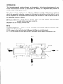
Expressions such as LEFT, RIGHT, FRONT or REAR used in this manual should be understood in accordance with following rules:
FRONT means the front grill end while REAR means the lifting arm end of the tractor.
LEFT or RIGHT means the left or right hand side of the tractor looking forward from operator's seat.
Right
t
Front
•
Left
Rear
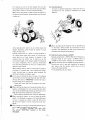
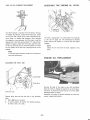
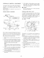
SERIAL NUMBERS
~".
~----1
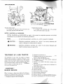
Tractor serial number
:z
Engine serial number
It is located at the right side of the transmission case
specifically upper side (under HST filter).
It is located at the right hand side of the cylinder
block, specifically injection pump side.
NOTES, CAUTIONS and WARNINGS
NOTES, CAUTIONS and WARNINGS are used in this manual to emphasize important and critical
instructions. They are used for the following conditions:
NOTE . .............. An operating procedure, condition, etc., which is essential to highlight.
A CAUTION . .......Operating
procedu res, practices, etc., wh ich if not strictly observed, will
resu It in damage to or destruction of machine.
A
WARNING . ...... Operating procedures, practices, etc., which if not correctly followed, will
result in personal injury or loss of life.
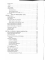
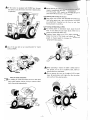
TREATMENT OF A NEW TRACTOR
All components of your tractor are subject to stringent
checking during assembly in the factory. However, a new
tractor should be carefully checked over by the operator
himself. For the first- 25 ~ 50 hours operation, heavy duty
work should be avoided. If heavy duty work is unavoidable,
drive in a gear one stage lower than you would normally
use, and run the engine at lower rpm.
"1M PORTANT"
50-HOUR
SERVICE
,
When the tractor is brand new, after the first 50 hours
running, the following service, maintenance and checking
should be carried out by th is instruction book.
1. Replace the engine oil filter and engine oil.
2. Replace the transmission oil.
3. Retighten all bolts and nuts, paying special attention to
those for steering linkage and wheel.
4. Check and adjust the fan belt tension.
5. Check the wheels to see if their condition is good and
tire pressure is correct.
6. Retighten the cylinder head bolts and adjust valve
clearances.
7. Front axle diff. case and gear case oil replacement of
4-wheel drive tractor.
8. Cooling water replacement.
9. Air cleaner element cleaning.
10. Clean the fuel filter.
11. Check the front hub for end-play.
12. Check the battery electrolyte.
13. Clean the hydraulic oil filter.
This 50-hour Service is an essential procedure for keeping
the tractor in top condition, so it must be done properly.
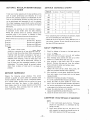
CONTENTS
SECTION 1. SAFETY PRECAUTIONS
A. General Operating Safety Precaution .......................... '........ .
B. Basic Safety Requirements for Maintenance ............................ .
C. Operation of the Tractor. . . . . . . . . . . . . . . . . . . . . . . . . . . . . . . . . . . . . . . . . . . . 2
SECTION 2.
EXTERNAL VIEW AND NOMENCLATURE OF EACH PART ..6
SECTION 3.
INSTRUMENTS AND CONTROLS ...........................8
Key Start Switch. . . . . . . . . . . . . . . . . . . . . . . . . . . . . . . . . . . . . . . . . . . . . . . . . . . .. 9
Glow Signal ......................................................... 9
Glow Plug .......................................................... 9
Tractor Meter ....................................................... 9
Battery Charge Warning Lamp ........................................... 9
Oil Pressure Warning Lamp ............................................. 9
Water Temperature Warning Lamp ....................................... 10
Fuel Meter ..........................................................10
Light Switch ........................................................ 10
Check Bu tton ....................................................... 10
Horn Button ........................................................ 10
Combination flash and turn signal switch .................................. 10
Th rottle Lever ....................................................... 10
Clutch ............................................................. 10
Brake.............................................................. 11
Park ing Brake ....................................................... 11
Foot Speed Control Pedal .............................................. 11
Power Take Off ...................................................... 11
Differential Lock ..................................................... 12
8-Speed Transm ission ................................................. 13
4-Wh ee I Drive Sh ift Lever .............................................. 13
Safety Starter Switch ................................................. 13
SECTION 4. OPERATION .............................................. 14
Before Operating the Tractor ........................................... 14
St,arting the Engine ................................................... 14
Starting in Cold Weather ............................................... 14
Engine Block Heater ..................................................14
After the Engine is Started .............................................14
Driving the Tractor ...................................................14
Stopping the Tractor .................................................. 15
Tread Adjustment .................................................... 15
Front........................................................... 15
Rear ........................................................... 16
Rear Wheel Installation ................................................16
Ballast Weight .......................................................16
Tire Pressure ........................................................16
r
Operator's Seat ...................................................... 17
Tool Box ...........................................................17
Drawbar ........................................................... 17
3-Point Linkage ...................................................... 17
Hydraulic System .................................................... 17
Flow Control Knob ................................................ 18
External Hydraulic Service ...................................... '"
.19
Power Take Off for Front Loader (Option) .............................. 19
P.T.O. Guard ........................................................ 19
SECTION 5.
REGULAR MAINTENANCE GUiDE ......................... 20
Service Schedu Ie ..................................................... 20
Service Schedule Chart ................................................ 20
Daily Inspection ..................................................... 20
A-Service (Every 50 hours of operation) ...... .' ............................ 20
50-Hour Service for a New Tractor .................................... 21
50-Hour Service for Other than New Tractor ............................ 21
B-Service (Every 100 hours of operation) .................................. 21
C-Service (Every 200 hours of operation) .................................. 21
D-Service (Every 400 hours of operation) .................................. 21
Maintenance I nterval Chart ............................................. 22
Lubrication Table .................................................... 23
Greasing Diagram .................................................... 24
SECTION 6.
PREVENTIVE SERVICE INSTRUCTION ..................... 26
Hood and Side Covers Opening/Closing .................................... 26
Checking the Radiator Coolant Level ..................................... 26
Coolant Replacement ................................................. 26
Precautions on Cooling System in Cold Weather ............................. 26
Antifreeze .......................................................26
Fuel System Air Bleeding .............................................. 27
Fuel Filter Air Bleeding .............................................27
Fuel Pump Air Bleeding ............................................ 27
Fuel Pipe Air Bleeding .............................................. 27
Fu.el Filter Element Replacement ..................................... 28
Cleaning the Fuel Tank ............................................. 28
Checking the Engine Oil Level. .......................................... 28
Engine Oil Replacement ............................................... 28
Engine Oil Filter Replacement .......................................... 29
Injection Nozzle Inspection ............................................. 29
Cylinder Head Bolt Tightening .......................................... 29
Valve Clearance Adjustment ............................................ 30
Valve Clearance Adjustment Procedure .................................30
I
Air Cleaner .........................................................30
Fan Belt Tension Adjustment ........................................... 31
Battery (Outside North America) ........................................ 31
Booster Connection ................................................ 32
Proper Procedure for Booster Connection ............................... 32
Proper Procedure for Removing Booster Cable ........................... 32
Proper Battery Service and Tips for Safety .............................. 33
Checking the Electrolyte Level ....................................... 34
Battery Recharging ................................................ 34
Lubricating the Tractor Meter Cable ...................................... 34
Transmission Oil Replacement ..........................................,34
Creaning the Hydraulic Oil Filter ..................................... 35
Checking the 4WD Front Axle Oil Level and its Replacement ................... 35
Checking the Oil Level .............................................35
Replacing the Oil of Front Axle ...................................... 35
Cleaning the Radiator Screen ...........................................36
Cleaning the Radiator ................................................. 36
Cleaning the Inside of Radiator ....................................... 36
Clutch Pedal Adjustment ............................................... 36
Brake Pedal Adjustment ............................................... 37
Differential Lock Pedal Adjustment ...................................... 37
Throttle Lever Adjustment ............................................. 37
Hydraulic Control Adjustment .......................................... 38
Position Control Adjustment ......................................... 38
Hydraulic Pump Relief Valve ........................................... 38
AC Generator ....................................................... 38
Starting Motor ....................................................... 39
Regu lator .......................................................... 39
Glow Plug ...................... , ................................... 39
Fuse .............................................................. 39
SECTION 7.
STORING ................................................ .40
Storage ............................................................ 40
. Reoperation After Storage ............................................. 40
SECTION 8.
WIRING DIAGRAM ........................................ .41
SECTION 9.
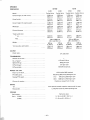
SPECIFICATIONS AND DATA ................................ 42
Engine .............................................................42
Cooling System ......................................................42
Fuel System ........................................................42
Lu brication System .................................................. .42
Air Cleaner ......................................................... 42
Governor ...........................................................42
Electrical System .....................................................42
Chassis Dimensions ...................................................43
Clutch .............................................. " ............. 43
Transm ission ........................................................ 43
Power Take Off ...................................................... 43
Brake .............................................................. 43
Steering ............................................................ 43
Hydraulic System .................................................... 44
3-Point Linkage ...................................................... 44
Drawbar ........................................................... 44
Tire ............................................................... 44
Travelling Speed ..................................................... 45
Capacities .......................................................... 45
SECTION 1. SAFETY PRECAUTIONS
REMEMBER: "SAFETY" IS ONLY A WORD UNTIL IT IS PUT INTO PRACTICE
Improper handling of the tractor could lead to an accident. Prior to the operation of the tractor, be sure to read this
Manual carefully and have a thorough understanding of all of the contents. In particu lar, the instructions given in this
section entitled "Safety Precautions" must be strictly followed.
2.
A. GENERAL OPERATING SAFETY PRECAUTION
A 1.
3.
4.
Observe all the safety precautions in this manual
when operating the tractor.
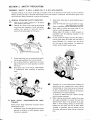
Operate the tractor while wearing tight clothing
that allows easy movement. Avoid loose jackets,
mufflers, ties, scarves, or loose sh irt sleeves to
prevent from being caught by moving parts.
Always work when you are in good physical condition by taking sufficient rest to avoid overwork.
Do n'ot allow children or adults having no knowledge of the tractor or tractor operation, to operate
the tractor.
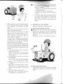
Never allow riders on the tractor, linkage drawbar
or attachments while travelling and operating
them.
A7.
8.
B.
Keep tractor steps clean to avoid accidents due to
slippage.
Cover the PTO shaft with a guard when not using.
Be sure to apply the brake and lower any attachment or implement before disassembling any part.
Never adjust or service the tractor when it is in
motion or while the engine is running.
Always adjust the brake or clutch properly in
accordance with the adjusting procedure in the
instruction book.
Do not remove the radiator cap while the engine is
running. Shut down the engine and wait until it
cools sufficiently. For removal, turn the cap to
the first stop to relieve pressure. To replace the
coolant, use the coolant recovery tank.
BASIC SAFETY
TENANCE
REQUIREMENTS
FOR
MAIN-
Always follow these maintenance instructions before
operating the tractor:
1. Immediately repair the head lights and work lamps
required to conform to traffic regulations where
the tractor is operated.
-1-
Hydraulic oil or fuel escaping under pressure can
penetrate the skin, causing serious injury. Before
disconnecting oil or fuel lines, be sure to relieve all
pressure. Before restoring pressure after repair,
be sure all connections are tight and all hydraulic
components are in normal condition.
If injured by leaked fluid, see a doctor immediately for proper treatment.
When refueling, be particulary careful first to stop
the engine completely to prevent the fuel from
igniting. Never refuel in the presence of an open
flame or while smoking. Always use funnel when
adding fuel and refuel only out of doors. When
refueling is completed, wipe any spilled fuel off
the tractor and securely fasten the cap of the fuel
tank.
A
9.
Before starting any work on electrical equipment
or work that may cause you to touch the electrical
part accidentally, first disconnect the battery
cables.
Never remove the ru bber cap cover at the positive
terminal of the battery cable end.
Before connecting the battery to the charger,
make sure that the charger switch is in "OF'F"
position. Be sure to connect the charger to the
correct term inals on the battery, (positive to
positive, negative to negative).
A great amount of hydrogen gas is generated by
the battery when it is being charged. Take precautions against fire: do not have any exposed flame
in the area where you are working.
Be sure not to cause any leakage of the electrolyte,
since it will corrode the skin or clothing. In case
of accident as described below, immediately seek
first aid, and see a doctor immediately for proper
treatment.
a) If the diluted sulphuric acid from the battery
has gotten into the eyes:
Cleanse the eyes with a lot of clean running
water for more than 15 minutes, while opening
the eyes widely.
b) If diluted sulphuric acid from the battery has
been swallowed:
Rinse the mouth with clean water immediately
and drink a lot of raw eggs or milk. Lie down
quietly.
c) If diluted sulphuric acid has gotten on the skin
or clothing:
Wash away the diluted sulphuric acid completely with a lot of clean running water and
neutralize with soap solution. Then rinse with
water.
d) If the diluted sulphuric acid is spilled:
Wash away with a lot of water or neutralize
with slacked Iime or bicarbonate of soda.
C.
10. Stop the engine and make sure the PTO shift lever
is in Neutral before performing any of the following services, including:
a) Removal of the propeller shaft between PTO
and any attachment,
b) Adjustment of PTO drive train and hitch.
c) Adjustment or cleaning of PTO driven attachment.
11. The steering wheel always has built-in play to
some extent, which is required for smooth meshing of sector gear and pinion gear. Always inspect
the amount of the play. Do not operate the
tractor if there is too much or too little play in the
steering.
OPERATION OF THE TRACTOR
Before driving the tracotr, follow these rules:
C-1 Before Starting and Driving the Tractor
Operate the tractor only when seated properly in
operator's seat and keep a firm grip on the steering
wheel at all times. Never attempt to perform any
operation of the tractor from anywhere else, on or off
th e tracto r.
Always wear a "hard hat" when operating the tractor.
A
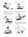
C-2 Starting and Driving the Tractor
Always operate the tractor at the proper speed which
enables you to keep the tractor under your complete
control.
-2 --
A
Never attempt to jump on or off a moving tractor.
A
When starting the tractor, operating any attachment or
engaging the PTO make sure that no one is in the way,
especially children.
I
To start travelling, lower the engine speed and release
the clutch pedal slowly. Abrupt releasing causes the
tractor to jump off.
Before leaving the tractor, stop the engine, remove the
key, apply the parking brake and make sure that the
engine has come to a complete stop, and any attachment is completely touching the ground.
AWhen starting the engine in an enclosed area or building, ensure proper ventilation by opening the doors
and/or windows to prevent carbon monoxide inhalation. Mount the extension exhaust pipe on the tractor
which has a cabin.
-r,,)j/
A
Slow down when operating the tractor on rough round.
f,") )
-3-
A If the tractor is equipped with
ROPS fasten the seat
belt before using the tractor and keep it fastened while
in operation.
A
Never operate the differentiallock
speed or travelling on the road.
For drilling the 4-WD tractor on the road, be sure to
place the 4-WD shift lever in OFF position.
C4 Steering and Turning the Tractor
Slow down your tractor and disengage the differential
lock before going into a turn, being careful to prevent
any attachment mounted on the front or rear from
hitting anyone or anything.
A
C-5 Towing and Operating on Hills
For towing work on downward slope, place the shift
lever in low speed and use engine brake. Never try to
reduce the speed with brake only.
Towing a heavy object on a hill is highly hazardous.
Widen the tread of the tractor and mount the wheel
weight or chassis weight to increase the stability and
operate with extra caution.
A
A
A Use
of the seat belt is not recommended for ·tractor
without ROPS.
A When operating the tractor on eigher a steep slope or
A
C-3 Travelling on Roads and Streets
For travelling on roads and streets be sure to lock both
brake pedals together before driving to prevent either
brake from acting independently.
A
flat ground, be sure not to suddenly steer, brake or
operate clutch or attachments.
Do not operate the tractor at the edge of cliff or steep
slope. Be particularly careful right after the rain when
soil is soft and may give way easily.
/
l
-4-
For towing, be su re to use the drawbar only. Set the
hitch point below the center line of the rear axle. When
using a chain, never try to move forward abruptly.
When using a long chain or cable to hitch the tractor to
the load, drive-the tractor forward slowly until all slack
is taken out.
C-6 Using Attachment
To mount or operate attachments, follow the instruction manual for the particular attachment for safe
operation.
A When using agricultural chemicals with an attachment
Avoid operating the tractor on an extreme slope that
appears hazardous, when forced to operate on such
slope, use extra care.
Driving forward out of a ditch or mired condition or
up a steep slope could cause tractor to tip over rear·
ward. Back out of such situation if possible. If the
situation does not permit you to back out, use the
front wheel weight or the chassis weight for balancing
the tractor lengthwise. Also in case any extra-heavy
rear mounting attachment is used, try to obtain better
balance in this manner.
When backing down a slope in reverse gear or going up
the grade in forward gear, never operate the clutch,
brake, th rottle lever or steering wheel abruptly. Be
particularly careful on slippery roads.
In any case of towing (by use of a rope or by hanging
up the front), be sure to place the both main shift lever
and sub shift lever at "NEUTRAL" position 50 long as
the rear wheels are on the ground.
* These shift levers shall not be placed at any other
speed range.
When starting the engine by towing the tractor with a
battery as discharged, be sure to place the main shift
lever at the 3rd speed step and the sub shift lever at the
high speed step, then operate the clutch slowly.
/). * Never place the sub shift lever at the low speed step.
~ When towing the tractor, be sure to keep the safety
speed. It is advisable to operate at 10 km/h (6.3 mph)
or less in towing the tractor under 20 HP and at
20 km/h (12.4 mph) or less in towing the tractor over
20 HP.
When towing or running on a steep downward slope, be
sure to apply the engine brake to keep safety speed.
Never run by inertia (coasting) with main shift
lever placed "NEUTRAL" position or the clutch
disengaged.
on the tractor, always follow the instructions in the
manual for the attachment as well as the instructions
provided by the chemical manufacturer.
C-7 Roll Over Portective Structure (ROPS)
Strongly recommends a ROPS (RollOver Protective
Structure) install to your tractor. A ROPS frame is
available for these tractor. Tractors can be rolled over.
Always tighten the bolts for ROPS mounting securely.
Exercise good care in seat belt installation as regard
belt strength and the bucket, which must not be
broken off or disconnected.
For further details, ask your delaer.
A
A
A
-5-
A
j
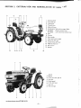
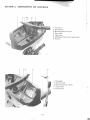
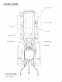
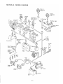
SECTION 2.
9
3
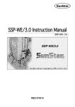
EXTERNAL VIEW AND NOMENCLATURE OF EACH PART
6
54
2
3
7 8
1.
2.
3.
4.
5.
6.
7.
8.
9.
10.
11.
12.
13.
14.
15.
16.
14
Steering wheel
Fuel tank cap
Head lights
Throttle lever
Main shift lever
Combination flash and turn signal lights
MT180/D ... Position control lever
MT160/D ... Lift, hold, down control lever
Seat
Fenders
Brake pedals
Foot speed control pedal
High-Low shift lever
4wheel drive shift lever
4WD AG front tire
AG rear tire
Bumper
16
2
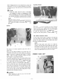
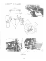
1.
2.
3.
4.
5.
6.
7.
8.
3
4
5
6
8
7
The above photoes show MT180D (4-WD).
-6-
Bonnet
Muffler
Front drive diff. gear case
Drag link
Clutch pedal
P.T.D. shift lever
Arm rest
Red rear light
f
2
4
3
5
6
7
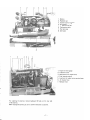
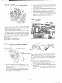
1 . Battery
2. Radiator cap
3. Cyclone type ai r cleaner
4. Air cleaner dust pan
5.
6.
7.
8.
Engine oil filler cap
Tachometer cable
Fuel tank cap
Alternator
1.
2.
3.
4.
5.
6.
7.
Engine oil level gauge
Injection nozzle
Solenoid for key engine stop
Fuel injection pump
Lead wire for water temp. warning lamp
Air cleaner hose
Radiator hose
8
2
4
5
6
7
For opening the bonnet, remove backward the hook on the rear side
of the bonnet.
When closing the bonnet, be sure to confirm the bonnet is secured.
-7-
-..,.....SECTION 3.
I
I
INSTRUMENTS AND CONTROLS
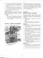
2 3 4 5
I
7
6
1.
2.
3.
4.
5.
6.
7.
2
3
Fuel meter
Check botton
Monitoring lamp unit (L.H.)
Horn switch
Light switch
Combination flash and turn signal switch
Fuse box
4
1. Glow signal
2. Key start switch
3. Monitoring lamp unit (R.H.)
4. Tractor meter
5. Throttle lever
-8-
.
i
•
KEY SART SWITCH (Engine on-off key switch)
TRACTOR METER
Heat position . . . . . . . . . Power applied to the glow plug
OFF position . . . . . . . . . Engine and all lights turned off
ON position . . . . . . . . . . Engine running and electrical
circuit energized.
START position . . . . . . . Starts the engine then key
returns to "ON" position.
The tractor meter indicates engine rpm.
ACAUTION
Be sure to remove key whenever tractor is not in
operation.
GLOW SIGNAL
When the starter key is turned to "HEAT" position, internal coil glows in red indicating that the engine is preheated.
The engine will be preheated in 5 sec. under normal temperature.
GLOW PLUG
The engine is fitted with speed heating sheathed glow plug
which preheat the combustion chamber so that the engine
may be started easily even in cold weather.
-9-
Indication of Meter
2,340 at P.T.O.
P.T.O. shift rotation
1st shift
540 rpm
1,793 at P.T.O. 3rd shift
1,000 rpm
BATTERY CHARGE WARNING LAMP
[In the monitoring lamp unit (L.H.)]
When the starter switch is set to "ON", this lamp lights up.
When the battery is being charged normally wh i Ie the
engine is running the lamp should go off. If the lamp
continues to light, stop the engine immediately and see
your Mitsubishi dealer.
OIL PRESSURE WARNING LAMP
[In the monitoring lamp unit (L.H.)]
When the starter key is switched "ON", this lamp lights up.
When oil is circulating normally while the engine is running,
the lamp turns off. If the lamp still lights up after the
engine has been started, stop the engine immediately and
check the engine lubrication oil level. If that is OK, see
your Mitsubishi dealer.
WATER TEMPERATURE WARNING LAMP
[In the monitoring lamp unit (R.H.)]
COMBINATION FLASH AND TURN SIGNAL SWITCH
When the temperature of the cooling water exceeds 110°C
(230°F), the water temperature warning lamp lights up.
When this occurs, lower the engine speed to about 900
rpm immediately and wait until the warning lamp goes
off. Then stop the engine and check the amount of cooling
water, the fan belt tension, the wiring, the temperature
gauge unit and the lamp bulb.
AWARNING
Be especially careful of the removal of the radiator cap.
FUEL METER
Indicates remaining fuel.
When the pointer comes over the "E" position, fill fuel as
soon as possible.
Two flashing lights are located on the rear of the fenders.
Anytime the tractor is operated on pUblic roads, the
flashing lights should be used.
The flasher switch is installed on instrument panel and it
is used when making a tu rn to right or left.
Turning the switch leftwise causes to flash the left-handside turn signal, and turning it rightwise causes to flash the
right-hand-side turn signal, respectively.
Also, pulling the switch upward places the turn signals at
both sides into the flashing condition.
Turning the switch in this condition leftwise causes the
left·hand-side turn signal to repeat flashing and the righthand-side turn signal to be placed in the lighted condition,
while turning it rightwise causes to occur the condition
just reverse to the above.
LIGHT SWITCH
THROTTLE LEVER
The head light switch is installed on instrument panel and
the operation is accomplished by turning the switch lever
clockwise.
OFF.
. . . . . . . . . . . . . Lights are off.
. . . . . . . . . . . . . Red tail light and meter panel
lights are on .
§o·········
~O
. . . Headlight are dimmed and directed downwards . . . . . . low beam
.............. Bright head lights .... high beam
CHECK BUTTON
Turn the key switch "ON" and push the check button with
the engine kept stopped. Then, all the warning lamps are
lighted except the turn signal lamps.
If not, ask the dealer for check.
HORN BUTTON
Horn is effective while key start switch is in "ON" position.
If not, ask the dealer for check.
-10 -
When the throttle lever is pushed forward, the engine speed
reaches the maximum. The speed range controlled by the
lever is 900 to 2,900 rpm (with no load). When the P.T.O.
gear is shifted to "1 st" at 2,700 rpm (rated engine rpm),
the P.T.O. shaft rotates at 623 rpm .
CLUTCH
When disengaging clutch you are advised also to lower the
engine speed. The life of the clutch depends on the operating habit of the user. The clutch works in combination with
PARKING BRAKE
the P.T.O.
ACAUTION
Lowering the speed, when the tractor is overloaded,
by half engaging the clutch or changing gear at high
speed will damage the clutch lining. Disengaging must
be performed completely in one clean quick movement
with the engine revolution lowered as much as possible.
1
NOTE
When the tractor is not used, the clutch should be disengaged by depressing the clutch pedal and the clutch
lever should be hooked so that clutch linings will not
get stuck.
BRAKE
The main brake is used for parking the tractor. Connect
the right and left brake pedals with the locking plate,
depress the brake pedal fully and lock with the stopper
lever provided beside right side of transmission case.
To release the parking brake, depress the brake pedal
strongly and the parking brake is released automatically.
FOOT SPEED CONTROL PEDAL
The foot speed control pedal is installed on the right side
of the step. When the hand throttle lever is in the idling
position, the engine speed can be controlled freely within
the range by depressing the pedal.
The brake is of internal expansion type and is dirt and
water proof.
There are two pedals provided on the right side of the
transmission case which are linked together by a plate. The
brake is operated by depressing these pedals. To stop the
tractor, lower the engine revolution, depress the clutch
pedal and then depress the brake pedal.
For turning in a confined space the right and left axles can
be braked independently by removing the plate linking the
right and left brake pedals. When travelling at high speed
or on roads make sure that the right and left brake pedals
are linked by means of the locking plate. When starting to
travel on roads after one of the brakes has been operated
more often than the other, check the balance of the right
and left brakes beforehand. It is necessary to check brake
balance once a week. If you fail to check the brake balance
or to Iink the right and left brake pedals, there is every
Iikel ihood that an accident will occur.
AWARNING
While travelling on roads, be sure to link the both
right and left brake pedals.
- 11 -
NOTE
When the hand speed control lever is in a high rev.
position, the foot speed control pedal also moves into
the position for those rev. When this is done the revolution cannot be controlled by means of the foot pedal
within the range below the rev. set by hand lever.
POWER TAKE OFF
£
By operating the PTO shift lever located on left hand side
of the transmission case, the three PTO speeds can be
selected.
DIFFERENTIAL LOCK
When shifting the PTO shift lever, lower the engine speed
depress the clutch pedal fully to interrupt the power from
the engine and make sure the machine is brought to a
complete halt.
Fi rst . . . . . . . . . . . . . . . .623 rpm/2 ,700 engine
Second . . . . . . . . . . . . . .919 rpm/2,700 engine
Tird . . . . . . . . . . . . . . 1,506 rpm/2,700 engine
Standard PTO speed . . . . . .540 rpm/2,340 engine
rpm
rpm
rpm
rpm
1,000 rpm/1 ,793 engine rpm
A
WARNING
When starting the engine be sure PTO lever is in "N"
(Neutral) position.
This device links the right and left wheels in the transmission and rotates them at the same speed to prevent either
wheel from slipping or to increase traction force.
Engaging the Differential Lock
Correct
Incorrect
A
CAUTION
1.
2.
3.
4.
5.
6.
7.
8.
When using a rotary tiller in the field with many
stones or stumps or hard soil, where a lot of shock
will affect on, care should be taken so that the
rotary tiller will not be damaged.
When using implements driven by PTO shaft, be
sure to refer to implement manuals and operate
them exactly as instructed.
When any implement is towed by the tractor, care
should be taken so that the universal joint does
not form an angle of more than 15°.
When the tractor is working with an impact load,
correctly adjust the slip clutch on the implement
side or use the shear pin of proper material so that
the PTO is not overloaded.
To reduce the thrust load to the PTO driven shaft
as much as possible, it is advisable to run a test
operation with an implement without any load.
Lubricate the PTO driven shaft well.
Avoid using a square-shaped drive shaft where
practicable.
Special care shou Id be given to the yoke position
so that the driven shaft is well balanced.
Before the tractor slips and the speed is lowered,
depress the pedal with you r right foot and engage the
differential lock. If the differential lock does not
engage at the first attempt, repeat the operation more
forcibly. If it still does not engage, lower the engine
speed and after disengaging the running clutch, repeat
the whole operation as described above. If either of the
left or right wheel has already begun slipping, turn the
throttle lever to the idle running or disengage the
clutch, then depress the differential lock pedal. Make
sure that the pedal is fully depressed. The farther the
pedal is depressed, the better the lock is in effect.
NOTE
Removing your foot off the pedal automatically
releases it, however if it is hard to release, depress
either side of brake pedal instantaneously.
How to Release the Differential Lock
Immed iately after the right foot is moved off the
pedal, the differential lock is automatically released by
force of the spring. However, it must be remembered
that the lock may not be released under special conditions. In th is case, the right and left brake pedals
should be quickly and alternatively depressed, then,
the differential lock will be set free. If the same occurs
while plowing, the brake pedal of the land wheel side
should be applied. The lock will be let out. When the
both right and left brakes are Iinked for towing a trailer,
operation of the steering handle to right and left allows
the lock to be free. When the tractor is stopped with
the differential lock applied, reverse running with a
jerk can release the lock.
ACAUTION
Avoid using the differential lock when operating the
tractor at high speed or running on a road.
-12 -
-
"
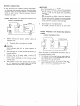
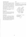
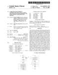
8-SPEED TRANSMISSION
4-WHEEL DRIVE SHIFT LEVER
The gear shift positions are as shown in the diagram below.
By combination of the Main and High-Low shift levers, six
forward speeds and two reverse speeds can be obtained.
The first, second, and third forward speeds and first reverse
speed can be obtained with High-Low shift lever in the
LOW position, and the fou rth, fifth, and sixth forward
speeds and second reverse speed can be obtained with the
High-Low shift lever in the HIGH position.
P.T.O.
i'sh ift
lever
The 4-wheel drive sh ift lever is located on the right side of
the transmission case.
4-wheel drive will be engaged by pushing the 4-wheel drive
shift lever forward.
With the 4-wheel drive engaged, proper power will become
available for the following cases:
1. For the operation on inclined ground, wet field or
sandy soil.
2. For the operation with front end loader, trailer or plow
attached.
3. In order to prevent lunging forward during rotary tilling operation on hard soil.
A
lever
CAUTION
1. Operate the 4-wheel drive sh ift lever only after
depressing the clutch pedal.
2. Be sure to place the 4-wheel drive shift lever in
"OFF" position for travelling on road.
SAFETY STARTER SWITCH
1 st Speed
4th Speed
2nd Speed
5th Speed
MT160/D and MT180/D are equipped with a safety starter
switch to prevent an accident in starting the engine. By
placing the High-Low shift lever in NEUTRAL, the starter
switch is connected to enable to start the engine.
LOW
:H: !
R 1 st Speed 3rd Speed
R 2nd Speed 6th Speed
Main Shift
HI G H
High-Low Shift
NOTE
To shift the gears, lower the engine speed and depress
the clutch pedal to disengage the transmission clutch.
After stopping the tractor, shift the gears.
-13 -
i
3
SECTION 4. OPERATION
STARTING IN COLD WEATHER
BEFORE OPERATING THE TRACTOR
1.
Before operating the tractor, read this instruction manual
carefully and learn it correctly. The manual has been
prepared for achieving tractor's maximum performance and
safety for your work with this tractor employed.
1. Check the fuel level in fuel tank and replenish as
necessary.
2. Check the levels of engine oil, transmission oil, and
front drive differential.
3. Check the lubrication at every specified point on the
chassis.
4. Check each bolt and nut for tightness.
5. Check the coolant level in radiator.
6. Check the fan belt tension for water pump, alternatorgenerator and cooling fan.
7.
8.
2.
3.
NOTE
In case fuel runs out, be sure to bleed the fuel system
after retilling the fuel tank, otherwise the engine may
not be started (or even stops soon after started).
Check the air pressure in tires.
Check every indicator lamp on instrument panel for
operation.
STARTING THE ENGINE
4.
5.
6.
7.
8.
Open the shut off cock for fuel.
Keep the parking brake applied.
Place the main shift lever, High-Low shift lever and
PTO shift lever in NEUTRAL.
Set the throttle lever midway between its idling and
high speed positions.
Turn the starter key to "ON" position, push the check
button to insure all warning lamps are on. And then
release the button and see that oil pressure warning as
well as battery charge warning lamps go on.
Depress clutch pedal all the way and tu rn the starter
switch to "START" position to start the engine. (If it
is difficult to start, turn the starter key to "HEAT"
position and wait for about 5 seconds before restarting.)
Immediately after starting, release the starter key. The
key will return to "ON" position automatically.
Check the oil pressure and battery charge warning
Iamps to see they went off. If not, stop the engi ne
immediately and inspect.
Perform warm-up run at about 1,500 rpm for about
5 minutes.
ACAUTION
1. Use of the starter should be limited for about 10
seconds per trial. If it is not successful, wait for
about 10 seconds before another trial. Using the
starter intermittently without waiting for certain
period of time, can cause the battery to run down.
2. Do not turn the starter while engine is running. It
can lead to the starter failure.
3. Be su re to perform the warm-u p ru n regard Iess of
the climate. Travelling before engine gets warm,
shortens the engine life.
-14 -
In the temperature below freezing point, it may be
necessary to use a engine block heater.
ACAUTION
After the engine has started comfirm that the engine is
running smoothly listening carefully to ascertain if
nothing abnormal sounds, and inspect for oil and water
leakage.
A
1.
2.
3.
The fuel injection pump of this engine adopts the
mechanism to ensure easier engine start by sufficient
injection of fuel when the throttle lever is fully pushed.
To start the engine specially in cold weather fully push
the throttle lever, heat the glow plug enough and
crank the engine.
WARNING
Do not use starting aids such as Gasoline or Ether in
the air intake. Explosion may result.
ENGINE BLOCK HEATER
For easier engine start in cold weather, an engine heater
may be used to heat engine coolant. Contact your nearest
dealer for installation.
AFTER THE ENGINE IS STARTED
1.
Be sure to check the oil pressure and battery charge
warning lamps to see they have gone off. If the lamp
does not go off, immediately pull the throttle lever all
the way backward and tu rn the starter key counterclockwise to shut down the engine, and locate the
cause to correct.
A
CAUTION
2.
Particularly, by starting the engine while oil pressure is
too low, serious trouble could occur because of insufficient lu brication.
Rotate steering wheel to see that front wheels turn to
desired direction.
DRIVING THE TRACTOR
1.
2.
With the engine running, hold the tractor with the
brakes if necessary.
By pulling hydraulic control lever backward, raise the
implement.
A
WARNING
Raise or lower the implement with sufficient caution
against any obstacle around.
3.
Bring the engine speed to about 1,500 rpm (warm-up
run).
Depress clutch pedal all the way.
Move each shift lever to desired position.
4.
5.
6.
While travelling, interlock left and right brake
pedals with locking plate so that they are appl ied
simultaneously.
A WARNING
For travelling at high speed, interlocking the left and
right brakes is particularly essential. Be sure not to
travel at high speed with left and right brakes being
independent to each other (not being interlocked).
7.
8.
9.
Do not attempt to stop tractor using brakes, which
may cause failure of transmission internals or prematured wear of brake linings.
To avoid damaging brake or transmission system, be
sure to release the parking brake before travelling.
While increasing the engine speed gradually, release the
clutch pedal slowly.
A WARNING
1.
2.
3.
4.
5.
6.
A
Release the clutch gradually. Releasing it suddenly
is hazardous causing the tractor to lunge.
Before travelling backward, be sure to check for
any obstacle beh ind the tractor.
For travelling on public road or working at high
speed, be sure to lock the left and right brake
pedals with locking plate so that both brakes are
applied simultaneously.
During high speed operation or travelling on road,
do not use differential lock. The 4-wheel drive
shift lever and PTO shift lever should be placed in
"OFF" and "NEUTRAL" positions respectively.
While travelling, remove your foot off the clutch
or brake pedals.
Independent use of left or right brakes should
only .be allowed for low speed operation.
8.
9.
Apply parking brake.
Push hydraulic control lever slowly forward to lower
implement to ground.
10. Remove the key.
11. Close fuel shut off valve above fuel filter.
A CAUTION
1.
Be su re to always apply the parking brake while
the tractor is in parking or standing.
Select flat and level ground for parking.
Apply blocks to rear wheels on the slope.
2.
3.
TREAD ADJUSTMENT
FRONT:
4-wheel drive front tread is as shown below_
MT160
AG tire
785 mm (30.9 in.)
785 mm (30.9 in.)
ES tire
800 mm (31.5 in.)
800 mm (31.5 in.)
800mm
(31.5 in.)
785 mm
(30.9 in.)
ES/F
AG/F
785mm
(30.9 in.)
CAUTION
For travelling with 3-point linkage attached, tie it
with belt or the like for prevention of swinging of
the lower link.
If any implement is mounted, turn the tractor
slowly paying particular care for the space.
8. Do not make a sharp turn at high speed. Be sure to
lower the engine speed before turning.
9. Before starting the operation on slope, check for
the existence of stone, irregularity, rutting or
other dangerous factors which could lead to an
accident. Avoid the operation on steep slope as it
can be a cause of tipping over.
10. On the downhill, use engine brake. Do not place
the main shift lever in "NEUTRAL" position.
11. For towing use a draw-bar only. Set the hitch
point below the center line of the rear axle.
MT180
800mm
(31.5 in.)
-'if
I
7.
AG/F
II
ES/F
2-wheel drive front tread is as shown below.
MT160
MT180
AG tire
720 mm (28.3 in.)
720 mm (28.3 in.)
ES tire
790mm (31.1 in.)
795 mm (31.3 in.)
720mm
-#--+----\.I- (28.3 in.)
-~=er
90mm
~311iO.'
i
STOPPING THE TRACTOR
1.
2.
3.
4.
5.
6.
7.
By pulling throttle lever, reduce engine speed.
Depress clutch pedal all the way.
Keep the brake depressed until the tractor comes to
a complete stop.
Move PTO shift lever to NEUTRAL.
Move main shift lever to NEUTRAL.
Remove foot off the clutch pedal slowly.
Stop the engine by starter key turned to OFF position.
-15-
AG/F
ES/F
720mm
-ff----I--H- (28.3 in.)
AG/F
m:i95m
m
313101
tW
ES/F
BALLAST WEIGHT
NOTE
1. Axle housing and gear case tightening torque
6 ~ 7 kg-m (43 ~ 50 ft-Ib)
2.
The slipping not only damages the tire but also results
in working inefficiency and greater fuel consumption.
Slipping, therefore, must be minimized as much as possible.
For that purpose, ballast weights are available as optional
equipment. It is recommended that the tractor be provided
with ballast weights when working in the place where
slipping is likely to occur. The ballast weights can be
attached on rear wheel discs and the front of the chassis.
Ballast can also be applied by putting water into the tires
instead of using the ballast weights. For this operation, pay
particular attention to the temperature and air pressure.
Front tire tighten ing torque
4-WD . . . . . 8.5 ~ 9.5 kg-m (61.4 ~ 68.6 ft-Ib)
2-WD . . . . . 12.0 ~ 13.5 kg-m (86.7 ~ 97.5 ft-Ib)
REAR:
The rear tread can be adjusted by changing the left and
right wheels to each other. This adjustment is applicable
to either specification - of 2-WD or 4-WD and ES or
AG tire.
2-WD and 4-WD tread
In cold weather where the temperature drops below O°C
(32°F), use water with antifreeze and never fill the tire
with only water. It is of course possible for you to employ
a combination of water in the tire and ballast weights.
Consult your dealer concerning the water injector and
method of injection.
Rear wheel weight: 2-WD and 4-WD AG & ES
33 kg (72.8Ib) x 2 = 66 kg (145.5 Ib)
Chassis weight: 2-WD and 4-WD
20 kg (44.1 Ib) x 1 = 20 kg (44.1 Ib)
MT180
MT160
Standard
tread
Max.
tread
Standard
tread
Max.
tread
AG tire
740mm
(29.1 in.)
890mm
(35.0 in.)
740mm
(29.1 in.)
890mm
(35.0 in.)
ES tire
790mm
(31.1in.J
840mm
(33.1 in.)
nOmm
(30.3 in.)
865 mm
(34.1 in.)
Rear wheel tightening torque. . . . . . .. 12.0 ~ 13.5 kg-m
(86.7 ~ 97.5 ft-Ib)
t t i
740 mm
(29,1 in,)
890 mm
(35,0 in,)
,
AG/R
AG/Max. R
(31.1
in.)
9 0in.)
m m f J o(33.1
mm
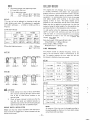
TIRE PRESSURE
Tire pressure should be checked frequency. Either too
high or too low pressure results in deterioration of the
tire. To properly maintain the tires, make sure that the
tire pressure is checked at least once a week.
,
Tire size
ES/R
ES/Max. R
AG
fr $;
740 mm
(29,1 In,)
890 mm
(35,0 In,)
,
AG/R
AG/Max. R
f
70mmm:65mm
(30,3
in,)
(34.1 in.!
ES/R
2.
Front 2-WD
4.00-9
4
Front 4-WD
5-12
4
Rear 2 & 4-WD
8-16
4
REAR WHEEL INSTALLATION
Make sure that rear tires are mounted so that the lugs on
the tire form the staggered V's in series as viewed from the
front of the tractor.
-16 -
AG
TR-13
TR-13
TR-15
2
2.0 kg/em
(28.4 psi)
1.5 kg/em'
(21.3 psi)
1.0 kg/em 2
(14.2 psi)
18x7.00-8
4
Front 4-WD
6-12
4
9.5-16
4
Tire size
Ply Std. pressure Valve type
Front 2-WD
4.50-10
4
Front 4-WD
5-12
4
Rear 2 & 4-WD
8-18
4
ES/Max. R
Avoid widening front tread of the 2 and 4-wheel
drive tractor by switching the right and left front
tires as this may cause serious troubles on the
steering linkage.
Check at frequent intervals to make sure that the
rear and front wheel are tightened securely to
specified torque and that the axle housing and gear
case are secured each other to specified torque.
2.0 kg/em 2
(28.4 psi)
2.0 kg/em 2
(28.4 psi)
1.0 kg/em 2
(14.2 psi)
Front 2-WD
Rear 2 & 4-WD
A CAUTION
1.
ES
,
Ply Std. pressu re Valve type
2.0 kg/em 2
(28.4 psi)
2.0 kg/em 2
(28.4 psi)
1.0 kg/em'
(14.2 psi)
TR-413
TR-13
TR-15
TR-13
TR-13
TR-218A
2
Front 2-WD
ES
Front 4-WD
Rear 2 & 4-WD
20x8.00-10
4
6-12
4
9.5-18
4
1.5 kg/em
(21.3 psi)
1.5 kg/em 2
(21.3 psi)
1.0 kg/em 2
(14.2 psi)
TR-413
TR-13
TR-218A
NOTE
Air pressure of the tires must be changed according to
the loading weight on the tires. For more details, please
call and talk with local dealer.
OPERATOR'S SEAT
The fixed type drawbar is provided as standard. To tow an
attachment or trailer, be sure to use the drawbar.
3·POINT LINKAGE
It is adjustable spring supported seat in 3 stages at increment of 30 mm (1.18 in.) to suit to the operator's stature.
TOOL BOX
This tractor is provided with a 3-point linkage
of category 1 .
The implement which is to be mounted, must match
the 3-point linkage.
NOTE
When an implement is towed with the linkage drawbar
installed on lower links, the lower links should always
be kept horizontal.
HYDRAULIC SYSTEM
Your tractor is provided with the live hydraulic system in
which a hydraulic pump is driven directly by the engine
camshaft and always makes the oil circulate to exert the
hydraulic pressure while the engine is running.
The tool box is located under the operator's seat. To use
the tool box, turn the seat downward to the front.
The hydraulic oil of exclusive use is reserved in the transmission case and passed through the oil filter, thus ensuring
effective operation.
DRAWBAR
Position control, flow control (down speed control) and
lock of the implement are possible with the hydraulic
control lever installed on the right side of the seat.
For external service, the hydraulic pressure can be taken
out by fitting an adapter plate to the delivery pipe installed
on the left side of the seat.
- 17-
FLOW CONTROL KNOB
POSITION CONTROL
Position control is provided for determining and holding
the position of an implement as desired by means of a lever.
Normally it is utilized for the work employing rotary tiller,
broadcaster, mower or rake. To use the position control,
operate the control lever in the following manner:
•
Pulling the lever backward will cause an implement to
rise.
•
Pushing forward will cause an implement to lower by
its own weight.
•
Placing the lever at certain position, causes implement
to move to and stop at the height corresponding to the
position of the lever.
•
For holding the height of the implement at certain
position constantly, use stopper A to fix the lever
position, which will make the lowered position of an
implement to be maintained at the constant height.
A
CAUTION
Stopper B is provided to prevent the hydraulic safety
valve from being actuated. Be sure not to move it for
any purpose other than hydraulic power take off.
For returning the displaced stopper B to its original
position, first operate the position control lever in
upward direction, then from the position where
actuating sound of the safety valve starts, slide the
stopper B downward by 5 to 8 mm and tighten it
there.
-18 -
MT160/D and MT180/D provide the flow control knob
which controls the lowering speed of the implement. It is
located in front of the hydraulic case under the seat.
When the knob is turned clockwise, the lowering speed
slows down, and when further turned, the control valve is
closed. As a result, the implement will be held in its position and will not move downward any further. Turning
the knob counterclockwise increases the lowering speed.
NOTE
Adjust the lowering speed according to the type of
an implement and operating condition.
Rotary tiller operation . . . . . . Lowering speed - Slow
Plow operation . . . . . . . . . . . Lowering speed - Fast
AWARNING
1. For travelling on the road, be sure to turn the flow
control knob all the way clockwise and lock it
there.
2. During tine replacement, or grass or straw removal
of rotary tiller, or during inspection of implement,
for the safety, place the position control lever in
upward position, shut down the engine and be sure
to lock the flow control lever.
EXTERNAL HYDRAULIC SERVICE
Lift arm
The hydraulic pressure can be used to control the implement installed to the tractor.
NOTE
When taking out the hydraulic pressure, be watchful of
oil level in the transmission case and sticking of the
pump to be caused by oil shortage.
PTI/4
iI I
J
HydrauliC
l:=~~ntrol valve
..
~~_,.
J'
P PT 3/8
N PT3/8 ~-~
T PT 3/8
Adapter
Spacer
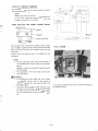
POWER TAKE OFF FOR FRONT LOADER (Option)
Hydraulic case
......_-Spacer
,....-IL----:.---I
Adaptor
TransmiSSion case
Relief valve cover
Hydraulic CirCUit for front loader etc.
For the power take off for the front loader, install a spacer
and an adapter, fastened to each other, between the power
take off on the left side of the hydraulic case and relief
P.T.O. GUARD
valve cover.
Control valve and operating lever is provided with the
implement.
NOTE
1. For any implement other than this front loader, if
it is provided with a control valve, use this power
take off.
However, it can not be used at the same time with
the front loader.
2. For installation of the front loader, consult with
your local dealer.
AWARNING
1. For operating the front loader, etc., do not place
the hydraulic control lever of the tractor at
"R ELI E F" position as it may cause trouble in the
hydraulic system.
2. For safety, during the front loader operation, have
the rotary tiller installed. The rotary tiller should
be raised all the way with the flow control knob
set at its lock position so that it will not be lowered.
-19 -
In any type of operation, be sure to install the PTO guard
for additional safety.
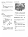
SECTION 5. REGULAR MAINTENANCE
GUIDE
SERVICE SCHEDULE CHART
To keep your tractor operating in the top condition and to
assure its proper performance and reliability for a long
period of time, periodic inspection is indispensable. If your
tractor is not periodically serviced, the result will be such
that its performance and operating life will be reduced.
Also a major breakdown is more likely to occur, which will
entail much more expense what you would pay for regular
maintenance.
Maintenance and servicing are very important, however,
the procedure is very simple. Carry out daily checking,
greasing and periodic service by carefully following the
instructions given in this manual. In addition to daily
inspection the following servicing must be carried out:
Hours of
operation
A-service
B-service
50
0
0
100
0
0
150
0
200
0
250
0
300
0
350
0
400
0
0
C-service
D-service
0
0
0
0
0
* After completing the first 400 hours of operation, repeat
the service schedule given in the above chart.
* Usually B service is carried out in every 100 hours. For a
new tractor, however, B service should be carried out at
the time of 50 hours service too.
50-hour service to be carried out on a new tractor.
A-service . . . . . . . . . . . . . . . . . . Service every 50 hours
B-service . . . . . . . . . . . . . . . . . . Service every 100 hours
C-service . . . . . . . . . . . . . . . . . . Service every 200 hours
D-service . . . . . . . . . . . . . . . . . . Service every 400 hours
DAILY INSPECTION
NOTE
The tractor should always be kept clean. Before
greasing or removing the oil pan plug and filter cap,
be sure to wipe the surface clean. When using tools for
repairing inside the engine, transmission, fuel tank or
hydraulic unit, clean the tools before use. Be careful
especially when refueling. If dust or water gets in the
fuel, engine trouble will be experienced, resulting in
loss of power and the unexpected necessity of parts
replacement. The tractor should be serviced indoors
where there is plenty of room and it is as clean as
possible.
SERVICE SCHEDULE
Observe the following service schedule. This service
schedule is applied to tractors which are operated under
normal conditions. When your tractor is frequently operated in muddy places, greasing must be carried out more
frequently and when the tractor is often operated in
dusty places, clean the air cleaner element and fuel filter
more frequently. Extra servicing must be carried out
according to particular situation.
1.
Check for leakage of oil, water or fuel and repair the
part as necessary.
2. Check the engine oil, transmission oil and cooling
water. If the level is not proper, replenish.
3. After finishing work, replenish with fuel up to within
25 mm (1 in.) below the fuel tank filler cap.
4. After working in dusty places, clean the air cleaner
element. Remove dried grass etc. from the radiator
front and clean the radiator and radiator screen.
5. Tightening nuts and bolts
Tighten the front and rear wheel fixing bolts- All
other nuts and bolts should be firmly tightened.
6. After working in a muddy place, grease the king pins,
front axle center pin and brake shaft via the grease
nipples provided.
7. Check the tire pressure and adjust if necessary.
If it is not as specified make necessary adjustment.
8. Check the brake and clutch pedals for correct free
play. If it is not as specified make necessary adjustment.
9. All moving portions must be cleaned and lubricated
with engine oil so that they work smoothly.
10. Check the electrolyte level in the battery, and if it is
below the specified level add distilled water.
11. Check the fan belt tension and if it is slack adjust it.
A·SERVICE (Every 50 hours of operation)
NOTE
1.
2.
-20-
A new tractor needs good attention. Following
should be read carefully to understand all the
things to be done.
Some items described here are the same as for
daily inspection but special care should be given to
them when carrying out the 50 hours service.
50-HOURS SERVICE FOR A NEW TRACTOR
1.
2.
3.
4.
5.
6.
7.
8.
9.
10.
11.
12.
13.
B-SERViCE (Every 100 hours of operation)
Replace the engine oil filter and engine oil.
Replace the transmission oil.
Retighten all bolts and nuts, paying special attention to
those of steering linkage and wheel.
Check and adjust the fan belt tension.
Check the wheels to see if their condition is good and
tire pressure is correct.
Retighten the cylinder head bolts and adjust valve
clearances.
Front axle diff. case and gear case oil replacement for
4-wheel drive tractor.
Cooling water replacement.
Clean the air cleaner element.
Clean the fuel filter.
Check the front hu b for end-play.
Check the battery electrolyte for it's level and specific
gravity.
Clean the hydraulic oil filter.
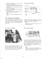
50-HOUR SERVICE FOR OTHER THAN NEW
TRACTOR
1.
2.
3.
Cleaning the air cleaner element
Blow compressed air to inside of an element and clean
it thoroughly. If the element is remarkably dirty, wash
it with a neutral detergent. Wipe off or blow off with
air the dust on the dust pan and body.
Clutch adjustment
Adjust the clutch pedal so that there is correct amount
of free play.
Cooling water replenishment
Check that the specified quantity of cooling water is
entered and if -not, fill with water up to within 25.4
mm (1 in.) below the filler cap. The full amount of
cooling water cannot be supplied in one operation.
When cooling water has been completely drained, fill
with new water, then run the engine at low revolution
for a short period and then fill to the specified level
again.
1.
2.
3.
4.
C-SE RV ICE (Every 200 hours of operation)
Carry out as follows along with DAI LY INSPECTION,
A-SERVICE and B-SERVICE:
1. Replace the transmission case oil.
2. Clean up the hydraulic oil filter.
3. Replace the oil in the front axle differential case and
the front gear case of the 4-wheel drive tractor.
D-SERVICE (Every 400 hours of operation)
Carry out as follows at the same time as DAI L Y INSPECTION, A-SERVICE, B-SERVICE and C-SERVICE.
1. Replace the air cleaner element.
The element is usually replaced in every 400 hours
but, for different operating conditions, judge the tim~
ing of the replacement by inspecting the element.
2. Replace the cooling water.
3. Clean the outside of the radiator.
4. Check the valve clearance.
5. Check the injection nozzle.
Check the nozzle condition and injection pressure.
6. Replace the fuel filter.
Check the water hose for damage and inspect connections for leaks.
NOTE
In cold weather, check the specific gravity of the
antifreeze water mixture.
4.
5.
6.
7.
8.
Replacing the engine oil.
The engine oil should be replaced at the first 50 hours
service and again replaced after another 50 hours of
operation.
Thereafter, replace the oil every 100 hours of operation.
Replace the engine oil filter with a new one.
Check the specific gravity of the battery electrolyte.
Clean the fuel filter.
NOTE
Carry it out at the same time as DAI LY INSPECTION
AND A-SERVICE.
Tightening nuts and bolts
Tighten all nuts and bolts because vibration is always
noticed when the tractor is operated. At the same time,
check the ballast weight bolts for tightness.
Greasing
See "Greasing diagram".
Check the front hub for end-play.
Washing the fuel filter.
Inspecting and replenishing with the electrolyte in the
battery.
-21-
s:
l>
Z
-I
m
Z
l>
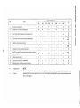
Ma inte nance I nterva I
Items
No.
I'V
I'V
I
1
Engine oil replacement
2
Engine oil filter element replacement
3
Fuel filter element cleaning-up and replacement
50
100
•
•
•
•
•
0
0
0
4
Air cleaner element deaning-up and replacement
5
Injection nozzle pressure check
6
Transmission oil check or replacement
CD
EEl
7
Hydraulic oil filter element cleaning-up
0
0
replacement.
"
EEl
Valve clearance check
EEl
Cooling water check or replacement
•
EEl
EEl
EEl
8
9
10
0
- - _ .__ ........
_ _ .....
-
200
250
0
350
•
•
"
0
300
0
0
0
0
400
I
•
0
0
0
..
EEl
EEl
EEl
0
0
EEl
EEl
EEl
EEl
EEl
Z
-I
•
•
•
100
:D
100
400
l>
0
m
<
r-
50
0400
(')
400
.200
EEl 100
:D
-I
0
50
•
.200
EEl 100
EEl
400
•
200
EEl
200
• . . . . . . Replacement
NOTE
o . . . . . . Cleaning-up
The intervals shown in the above chart regarding replacing, cleaning-up and checking are for the
standard. Perform each service so as to meet the requirement depending upon the operational condition of the tractor.
EEl • • • • • • Check
m
100
•
EEl
z(')
0
EEl
4-WD front axle diff. case and front gear case oil check or
Specific gravity of battery electrolyte check
-11- -
0
150
Thereafter
every
:t
l>
~--
--------~.~"-~
..--
~,.~.------"-
r-
C
CO
::0
n
~
o
Z
-I
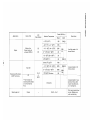
Application
Kind of Oil
API
Classification
Motor oil or
Super tractor oil
universal (STOU)
CC
CD
r-.,)
w
I
Description
Single
5W
-20 - O°C (-4 - 32°F)
lOW
-10-l0°C (14- 50°F)
20W
Multi
5W-20
10W30
OR
GL-3
or
better
* Farm tractor use
transm ission/hydrau lic
oil or multi~ervice
fluid.
Steering gear oil
Grease
20
10-30°C (50-86°F)
30
30°C (86° F)-
40
20W-40
Below O°C (32°F)
75W
-
-10-30°C (14-86°F)
80W
80W-90
0- 35°C (32 - 95°F)
85W
100C (50°F) & above
90
All seasons
-
~
0-20°C (32-68°F)
Gear Oil
Transmission/Hydraulic,
4·WD Front Axle.
rm
Grade (SAE No.)
Ambient Temperature
- 10°C (14°F)
Engine
»CO
NLG1 - No.1
Use High grade oil of
famous brand.
Use good grade oil of
famous brand.
85W140
Use good grade oil supplied by famous farm
tractor manufacturers
or oil companies.
Not requiring periodical
service. Replace only
when overhauling.
I
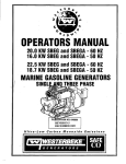
GREASING DIAGRAM
King pin (2-WD)
Center pin
Tie rod end
Drag link end
Clutch pedal boss -
_ _ _ ~_ _ '
This figure shows MT180D.
The greasing part of MT160/D
is same as MT180/D.
-24 -
CD
@
· (2-WD)
King Pin
Center pin
Whee I h ub (2-WD)
Tie rod end
n
\
1
1
U
CD
®
Drag link end
-25-
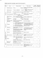
COOLANT REPLACEMENT
SECTION 6. PREVENTIVE SERVICE
INSTRUCTION
This section provides servicing instruction required for
regular maintenance and adjustment and its procedures.
NOTE
When carrying out the maintenance services or adjustments, place the tractor on as open and level ground as
possible. Before removing caps, plugs, and covers, wipe
clean the surrounding surfaces so as not to allow dust
or dirt to enter inside of the engine and the tractor.
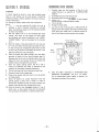
HOOD AND SIDE COVERS OPENING/CLOSING
Before opening the hood for pre-start inspection or light
servicing, push a knob at the hood rear in the direction of
the arrow marked on knob.
CHECKING THE RADIATOR COOLANT LEVEL
•
Remove the radiator cap to see if the coolant is upto the
filler port.
•
A
CAUTION
1. Use clean soft water only.
2. River water, etc. may cause rust, corrosion or
clogging in the radiator or engine.
3. See paragraph "ANTIFREEZE" for its use.
Loosen the coolant cock at lower right of the engine
and drain the coolant.
For replenishment, remove the radiator cap and enter
water upto the radiator filler port.
AWARNING
Be sure to loosen the coolant cock only whi Ie the
engine is cool.
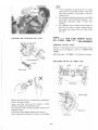
PRECAUTIONS
WEATHER
Radiator cap
ON
COOLING
SYSTEM
IN
COLD
Frozen cooling water may damage the cylinder block. To
avoid such a trouble, mix antifreeze into cooling water, or
thoroughly drain cooling water from the cylinder block in
case the tractor is stored or left unused for a long time in
cold weather.
AWARNING
Do not remove the radiator cap except for checking
the coolant level or coolant replacement. Removing
the cap immediately after operation is hazardous
because pressurized hot water will jet out. Stop the
engine and wait until it cools down before removing
the cap.
ANTIFREEZE
When adding antifreeze solution, the following rules should
be observed, otherwise, the cylinder block will rust.
1. This tractor's engine is of a diesel type and its cylinder
block is made of cast iron. Therefore, suitable a{ltifreeze solution for such a cast engine block must be
used.
2. Before adding mixture of antifreeze and water, completely drain cool ing water and clean the radiator with
detergent.
3. Water to be added to antifreeze should be clean soft
water.
4. When antifreeze is no longer used, drain and wash the
cooling system using detergent and fill it again with
clean water. Do not re-use antifreeze drained from the
engine.
-26 -
..
5.
6.
7.
8.
9.
Treat antifreeze carefully so that it may not remove
paint from the cylinder block.
Any antifreeze solution (antifreeze and water), even if
it is permanent antifr~ze, snQuld ffet be used for more
than 2 years.
Confirm that there are no leak from the hose connections or cylinder head gasket.
Antifreeze with proper density to suit the climate in
your area should be used.
When antifreeze is used over a long period in winter,
measure the specific gravity frequently.
NOTE
Consult your dealer concerning detergent and antifreeze.
FUEL PUMP AIR BLEEDING
Overflow pipe
"
I
Injection pipe
Nozzle holder
n
Injection pump"!
Air vent screw
(0'\:
r"
"
\~
;?
\ I',lJ
/ \
FUEL SYSTEM AIR BLEEDING
If fuel is exhausted and the engine stops or when the fuel
filter element is cleaned, air is induced into the fuel line.
In such case, the fuel system must be bled after refilling
the fuel tank. If air remains in the fuel line, the engine cannot be started_
Loosen the air vent screw of the fuel pump to let the fuel
to overflow after fuel filter air bleeding_ When no more air
bubbles is noticed in the fuel, tighten the screw.
FUEL FILTER AIR BLEEDING
FUEL PIPE AIR BLEEDING
Fill the fuel tank up to proper leveL Loosen No.1 air vent
screw sh own in the above photo and tighten it up after
filling with fuel until no air is noticed. Then loosen No.2
air vent screw, fill with fuel until no air is noticed and
tighten up the air vent screw in the same manner.
-27 -
NOTE
With this operation, the engine should start, but if not,
bleed the injection pipe.
Loosen the nut of the injection nozzle as shown above and
shift the throttle lever to high speed position. Then, start
the engine by operating the starter motor and make sure
the fuel is discharged properly at the loosened nozzle
connection. Tighten the nut to the specified torque.
Start the engine according to the steps given in "OPE RATING THE TRACTOR".
NOTE
Unless air is completely bled, the engine can not be
started; in such case, perform air bleeding again to let
remaining air completely out of the system.
.
FUEL FILTER ELEMENT REPLACEMENT
CHECKING THE ENGINE OIL LEVEL
Fuel filter element is inserted in the filter body in the cup.
To replace the element, close the filter body cock, loosen
the ring nut and remove the cup. After removing the ele·
ment, clean it or replace it, as necessary. After installing
the cleaned or new element to the filter body, install the
cleaned cup to the body with care about "0" ring and then
tighten it enough. Loosen the air vent screw, open the cock,
fill the cup with fuel, and after confirming there is no more
air left, tighten the air vent screw, ensuring there is no fuel
leakage.
The level is appropriate if it comes between two markings
at the end of gauge rod. The level should be checked
before starting the engine or 5 minutes after the engine
stopped.
NOTE
Check the oil level with the engine stopped in any
event.
NOTE
In case the engine won't start, loosen the fuel pump air
vent screw and purge it.
ENGINE OIL REPLACEMENT
CLEANING THE FUEL TANK
Cover for mud
Remove drain plug and clean the tank in the following
cases.
1. Every 600 hours of operation.
2. In case kerosene was entered for cleaning purpuse,
or water or dirt is in the tank.
-28 -
Remove the plug of the engine oil pan and completely
drain the used oil. Supply the specified oil up to the specified level. It should be noted that dirty oil is more easily
discharged when it is warm.
Replacing the engine oil should be carried out while the
tractor is placed horizontally.
X
Filler cap
o
approx.4°
When the injection pressure of the nozzle is lowered or
injection deteriorates, the exhaust gas becomes extremely
black resulting in the loss of engine power and the engine
will also make greater noise. Be sure to always maintain the
correct injection pressu re of 120 kg/cm 2 (1,706.97 psi).
Fill with new oil from filler port. Make sure that the filler
cap is tightened securely before starting the engine.
ENGINE OIL FILTER REPLACEMENT
When necessary, the cartridge type engine oil filter shou Id
be removed with the special tool, and replaced with a new
filter.
CYLINDER HEAD BOLT TIGHTENING
NOTE
1. Lightly apply the engine oil or grease to the seal
surface of the oil filter before mounting.
2. After the oil filter has been screwed in and the
rubber seal comes in contact with the case surface,
screw in the filter 2/3 turn further by hand.
3. After mounting, start the engine and inspect the
seal surface for leaks.
4. Replacing the filter causes the oil to be reduced by
the volume of the filter. Recheck the oil level after
running the engine for 5 minutes.
Front
.......
o
7
4
o
02
INJECTION NOZZLE INSPECTION
o
o
6
o
5
II
8
o
03
Tighten the cylinder head bolts of a new tractor after
50 hours of operation. When the old gasket has been
replaced with new one, tighten the bolts to the specified
torque.
Tightening torque of the cylinder head bolts:
7~ 8kg-m (51 ~58ft-lbs)
M10
M12 11 ~ 12 kg-m (80 ~ 87 ft-Ibs)
Bolt tightening sequence is as shown in the Figure. For
uniform tightening of the bolts, the first tightening should
be for half the specified torque and then tighten it further
until the specified torque is reached.
NOTE
After tightening the cylinder head bolts, adjust the
valve clearances.
-29 -
1.
.... 1!2
.. L ... 2
..
2.
VALVE CLEARANCE ADJUSTMENT
3.
4.
A
B
Position the piston in No.1 cylinder at top dead center
on compression stroke and adjust its intake and exhaust valve clearance.
Then rotate the crankshaft 240 deg. clockwise to move
the piston of No. 3 cylinder to top dead center on
compression stroke, and adjust its valve clearance.
Then rotate the crankshaft 240 deg. clockwise to move
piston of No.2 cylinder to top dead center on compression stroke, and adjust its valve clearance.
AIR CLEANER
Adjust the valve clearances when the sound of the tappets
is loud or when the engine does not run smoothly without
anything abnormal with the fuel system.
Adjust the valve clearances by loosening the lock nut (B),
the adjusting screw (A) using a screwdriver and then applying a thickness gauge to (C). When locking the adjusting
screw by means of the lock nut (B), support the adjusting
screw firmly using a screwdriver so that both are not
rotated together.
Valve clearance: Intake & Exhaust
0.25 mm (0.01 in.) in cold condition.
Element
~
VALVE CLEARANCE ADJUSTMENT PROCEDURE
~
No. 2 Top
1-'r:s\I
Top Dead Center Mark
W;"'""'
~
,
D,,'p,"
~
Clamp
No.1 Top
Injection Timing Mark The air cleaner element, when remarkably stained or
clogged, may prevent smooth start of the engine or deteriorate its performance, preventing normal operation. Keep
the element always clean to ensure full performance of
\
engine.
No.3 Top
1.
The valve clearance should be checked with a cold
engine and with the piston at top dead center on the
compression stroke.
The top dead center on the compression stroke of
No.1 piston can be determined by the timing marks on
the crank pulley and timing gear case.
-30 -
Clean the element in the following procedure:
1. Remove the dust pan clamp and take out the dust pan.
Clean the separator plate ass'y and dust pan.
2. Unscrew the wing bolt and take out the element. Blow
the compressed air to remove dust completely. Blow
out the dust from the inside of the rubber seal and
tap hole.
3.
4.
Proper fan belt tension is for 1 0 ~ 12 mm (0.4 - 0.5 in.)
deflection with a thumb pressure applied halfway between
the crank pulley and alternator pulley. To adjust the ten·
sion, loosen the alternator bracket bolt and the adjust
plate bolt and move the alternator in or out. After proper
tension is obtained, tighten the bolt securely. Check the
belt for cracks and damages.
The element may be washed in synthetic detergent.
After washing, rinse the element completely and
dry before mounting. Never use it before drying up
completely.
Be careful not to allow the dust in the body ass'y and
on the pressure-fitted surface of the element seal to
enter the air hose. Disconnect the air hose when
cleaning the cleaner body by blowing the air.
Assembling the element
Assemble the element to the body and fasten with the wing
bolt completely. Assemble the separator plate ass'y to the
dust pan ass'y and install it to the body ass'y taking care of
the top mark.
BATTERY
(OUTSIDE NORTH AMERICA)
The battery equipped is POL YM ION battery, model
NX100-S6L (S). Though small-sized, it shows 40% higher
perfromance as compared with conventional batteries of
the same size_
NOTE
1. When operating in extremely dusty conditions,
service the filter more frequently than specified.
2. Clean the element with compressed air below
7 kg!cm 2 (100 psi).
1.
The specific gravity of electrolyte is 1,280 ± 0.010
at 20°C (68°F).
NOTE
Shipment for North America does not contain battery.
Read battery manufacturer's manual and follow.
FAN BELT TENSION ADJUSTMENT
ACAUTION
When the battery is not used for a long period of time
in cold weather, check the specific gravity and charge
the battery periodically.
2.
3.
4.
5.
6.
7.
The level of electrolyte should be between the lower
and upper levels indicated on the outside of the battery
case. Particularly in hot weather, frequently check
the level of battery electrolyte.
I n order to prevent the development of rust or other
corrosion at the battery terminal, coat the terminal
lightly with lubricant.
Before demounting the battery, be sure to shut down
the engine and turn off all the electrical switches.
Battery cable at earthing end (negative terminal end)
should be disconnected first.
For cleaning the terminal stud, first remove the battery
cable then use a wire brush for brightening it.
For the reinstallation of the battery, make sure to set it
on the battery support properly.
For connecting the battery cables, connect
end of it
first, followed by earthing end.
®
ACAUTION
The electrical system is of negative earth type. Care
should be taken to ensure that the battery terminals
are correctly connected when installing the battery.
8.
-31-
For dependable battery service, see your local dealer.
Wi
BOOSTER CONNECTION
WARNING
Do not fail to perform in above order.
During the final connection, spark will be generated.
Therefore, connect the
clip to the engine block at
as far away point from the battery that is generating
gas as possible.
Before connecting the cables, remove the electrolyte
port plugs where possible, because as long as such plugs
have been removed, the explosion will be smaller even
if it may catch fire resulting in smaller damage.
In case the battery has run down making it impossible to
start the engine, the booster is used for starting the engine
using good battery of the other vehicle (12V specification
vehicle) as power source. Following procedure should be
observed in such case:
8
PROPER PROCEDURE FOR BOOSTER CONNECTION
CORRECT CONNECTION
Troubled tractor
5.
r---~
Start the engine on the troubled vehicle.
If the engine is difficult to start, try to start it after
starting the engine of the normal veh icle.
Engins
~~
PROPER PROCEDURE FOR REMOVING BOOSTER
CABLES
----
CORRECT DISCONNECTION
1.
Before connecting the booster, carefully check the
followings to see:
III
That the spring in the cable clip is normal.
41&
That cable or clip is not broken or corroded.
Troubled tractor
~)
E __
A CAUTION
Select a booster cable with as large a capacity as
possible.
2.
Stop the engine of the vehicle (source side) which is in
normal operation.
3.
Connect a clip of the booster cable (in red) to
terminal of the battery on the troubled vehicle and
firmly connect another clip to
terminal of the
normal vehicle.
Then connect a clip of another booster cable (in black)
to 8
terminal of the normal vehicle and finally
connect another clip firmly to the engine block.
CD
CB
4.
-32 -
-:-1I
,.----
~
After the engine is started, remove the booster cables in
the reversed procedure of above.
1. First remove the 8end clip from the engine block of
the troubled vehicle, then remove another clip from
the
terminal of the normal vehicle.
8
2.
CD
Then remove a clip from
terminal of the normal
vehicle, followed by removal of another clip from the
terminal of the troubled vehicle.
CD
PROPER BATTERY SERVICE AND TIPS FOR SAFETY
Work
e
Proper servicing
Item
Tips for safety
Check
Watch for
electrolyte explosion
Electrolyte level
If low . . . . . . . . . . . . Replenish
Watch for soiling with leaked
electrolyte
0
Specific gravity
If below 1.200 (20°C) ... Charge
o Watch for splashing the elec·
trolyte.
o See "Battery Recharging".
0
Battery tester
If turned to yellow or red. Charge
Watch for sparks.
0
0
.;:;
If soiled . . . . . . . . . . . . . . Clean
(.)
<ll
0U)
If deformed or cracked . . . . . . . .
Replace the battery
Electrolyte port
plug
Soiled, deformed or loosened . . . .
Clean, Check, Retighten
Check for clogged plug hole.
Terminals and
bracket
Loosened . . . . . . . . . . Retighten
Watch for spark.
Corroded . . . . . . . . . . . . . Clean
Prevent leakage.
Replenishing with
electrolyte
Replenish with distilled water
upto specified level
Do not over·replenish.
0
Perform the charging in the well
ventilated place. Watch for current, temperature, generation of
sparks, sulfuric acid mist or gas.
Remove port plugs.
0
-e
ON
<ll
(.)
e
ro
e
Charging
Connect clips properly to (E)
and 8 terminals, then close
battery charger switch.
Open the battery charger
OFF
switch then disconnect cl ips.
<ll
+-'
e
ro
--- j - - -
~
Tightening
Tighten term inals and mounting
bracket fi rm Iy.
Cleaning
Clean battery surface, terminals
and bracket. Watch for clogging
the filler port plug holes.
Terminal
O'l
e
Disconnect: Earth ing end
8
e
0
::J
0
E
"0><ll
Mounting bracket
0
o<S~
.- .D
Install: Select proper battery for
the tractor (for replacement),
O'l~
e ro
------
<ll
::J..l:
0 .....
~b
Battery
Transport: Safely and surely,
--------
<ll
OJ
Battery with
electrolyte
0
0
Watch for sparks.
Install: Do not allow looseness.
0
0
first.
Demount: Disconnect at terminals
first.
0
------
Avoid damaging by over-tightening or rattling. Avoid spark
generation with tools, leak or
damage,
-
t---
Tighten bolts and nuts to proper
torque.
Watch for sparks due to tools.
0
0
0
0
Watch for leak or spark,
0
0
Watch for short circuit or leakage of electrolyte,
Particularly keep away from
0
0
-- --
Watch for terminal positions of
(E),8·
Do not drop or bang,
--- -----
Select dry place without direct sun
for storage.
Periodical make-up charge.
~
0
+-'
(f)
0
Connect: Earthing end last.
';:;
1::
Watch for leak or being soiled
with electrolyte.
External appearance
Disposal of baltery
Ask your local dealer for disposal.
~,
-33 -
CHECKING THE
ELECTROLYTE
1.
LEVEL
2.
Upper level
~
no
\
on
3.
I
!
With the meter cable removed, pull out the wire
from it.
Wipe the wire with cloth and dip it in engine oil for
a minute or two.
Hang it for about five minutes to dry, then replace
the cable. Install the cable being carefull of the inner
shaft di recti on.
Lower level
---
TRANSMISSION 01 L REPLACEMENT
!
r-
Battery electrolyte level
The amount of electrolyte should be between the lower and
upper levels indicated on the outside of the battery case.
Particularly in hot weather, frequently check the level of
battery electrolyte.
AWARNING
During battery inspection, watch for fire and be careful
not to touch the electrolyte with clothing or part of
your body. See "Basic Safety Requirements for Maintenance" in SAFETY PRECAUTIONS.
BATTERY RECHARGING
1.
2.
For charging the battery on this tractor, a slow charging operation should be carried out at 4.5 amp.
I n case the specific gravity is below 1.200, make lower
rate charging at 3 amp.
For more information, consult local dealer.
NOTE
Don't forget to turn off the lamp and don't treat the
battery in such a way as may be discharged rapidly.
LUBRICATING THE TRACTOR
METER CABLE
Inner shaft
---{J...J
Tractor meter side
Engine side
-34 -
Remove the drain plugs, both right and left, under the
rear part of the transmission case, and drain the transmission oil.
NOTE
When replacing the transmission oil, it is necessary to
clean oil filter element at the same time.
To fill the transm ission case with oil, tighten the drain plugs
first, and remove the transmission oil level plug and then
pour the oil into the filler port in the shift cover until
oil overflows from the transmission oil level plug port.
NOTE
1. If the transmission oil drained has to be reused,
wipe clean the surrounding surfaces of the drain
plug before draining, so that dust or dirt will
not get into oil.
2. Oil replacement should be carried out in every 200
hours under normal operating conditions. If oil
deteriorates excessively, replace it earl ier than
specified.
3. For installation of the oil filter make sure that the
pipe end of the filter is securely inserted into the
hole beside the suction pipe, and then install
the cover.
CHECKING THE 4-WD FRONT AXLE
OIL LEVEL AND ITS REPLACEMENT
CLEANING THE HYDRAULIC OIL FILTER
CHECKING THE OIL LEVEL
Remove oil level plug to check that oil flows out. If not,
add gear oil. For changing oil, refer to "LUBRICATION
TABLE".
Specified quantity: MT180HD - 2.5 Q (3/5 gal, 1/3 guart)
REPLACING THE OIL OF FRONT AXLE
O-ring
o
Filter screen
Drain plug
Oil level plug
Remove the filter at the time of draining the transmission
case oil, and clean the filter.
Loosen two bolts and remove the hydraulic oil filter
under the right part of the transmission case.
The removed oil filter should be thoroughly cleaned in the
detergent solution.
If the filter has been damaged, replace with a new one.
After installing the filter, make sure there is no oil leakage.
-35 -
t
1.
2.
Check the radiator for clogging, and remove large dust,
straw, etc. if any, first with hand.
Blow with clean water to wash away remaining dust or
straw.
A CAUTION
Be careful not to damage the radiator since damaged or
deformed radiator will reduce the cooling efficiency.
CLEANING THE INSIDE OF RADIATOR
1.
2.
3.
Remove drain plugs (3 locations) and let the oil flow
out.
Wrap the drain plugs with sealing tape and tighten it.
Enter new gear oil specified through filler port.
Clean radiator and engine coolant system with cleanser in
the following cases:
ell
After 600 hours of operation
•
Adding anti-freeze.
•
Replacing coolant eliminating anti-freeze.
A CAUTION
For cleaning the radiator, read the instruction on
cleanser carefully, and observe the instruction.
A CAUTION
Replace oil at the first 50m hours and in every 200
hou rs thereafter.
CLEANING THE RADIATOR SCREEN
1.
2.
CLUTCH PEDAL ADJUSTMENT
Open the bonnet and remove the radiator screen.
After removing large dust, straw, etc. with hand, rinse
with clean water.
CLEANING THE RADIATOR
Clutch pedal free play is very important and it must be
always maintained to be correct. If there is no free play, the
clutch disc will wear quickly, while too much free play will
cause difficult disengagement of the clutch even if the pedal
is fully depressed, resulting in hard gear shift.
•
Amount of free play should be 20 to 30 mm (0.79 to
1.18 in.)
ell
Adjust it in the following manner:
1) Remove the snap pin and clevis pin of clutch rod.
2) Adjust the amount of play by turning the joint.
Tu rn-in . . . . . . . . . Reduces the amount of play
Turn-out . . . . . . . . Increases the amount of play
NOTE
This adjustment is important for maintaining the
clearance between the release lever and the release
bearing to obtain a smooth gear shift and transfer all
the driving power to the transmission.
-36 -
BRAKE PEDAL ADJUSTMENT
DIFFERENTIAL LOCK PEDAL
ADJUSTMENT
Free play of the brake pedal must be maintained within
the correct range, otherwise, accident may occur or power
will be lost.
Before the brake on one side becomes unadjustable even by
means of the rod, caused by earlier wear of the brake lining
due to its more frequent use than the other, periodically
interchange the right and left brake shoes. Special care
should be taken in the case of more frequent using one
brake than the other.
The play of the brake pedal is appropriate if it is 20 to 30
mm (0.79 to 1.18 in.).
Adjust it in the following manner.
1. Remove a joint pin at the rear of brake rod, and loosen
locknut.
2. Adjust the amount of play by turning the joint.
Turn-in . . . . . . . . . . . . Reduces the amount of play
Turn-out . . . . . . . . . . . Increases the amount of play
After obtaining the specified dimensions on each side,
check the performance in the following procedure:
•
Effectiveness
Perform the single-side braking and pivot turn to make
sure of the effectiveness of the brakes (each side).
•
Uneven braking
Interlock the right and left brake pedals with link plate
and drive the tractor normally. Step on both brake
pedals simu Itaneously and check the trace of tire
slippage for uneven braking. If the tractor stops
straight, braking is normal. If it stops with turning,
readjustment is required.
-37 h
Loosen the lock nut on the differential lock pedal stopper,
and screw in the stopper bolt. With pedal depressed, adjust
the stopper bolt so that it lightly contacts the pedal. Then,
screw out the stopper bolt by a quarter to half turn and
lock the stopper bolt.
THROTTLE LEVER ADJUSTMENT
The engine speed can be controlled by operating the
throttle lever on the right side of the instrument panel.
The range of speed control is as follows:
Low idle speed. . . . . . . .. 900 rpm
High idle speed ......... 2,900 rpm
1.
Place the throttle lever in the low idle speed position,
and loosen the nut securing the speed control rod to
the joint. While watching the tractor meter on the
instrument panel, turn the nut so that the engine idles
at 900 rpm, and lock the nut.
2.
Pushing the throttle lever fully forward makes the
engine to run at the maximum of 2,900 rpm.
Pulling the throttle lever fully rearward causes the
engine to run at the low idle speed.
3.
NOTE
1. The high speed adjusting bolt is pre-adjusted and
sealed, before leaving the factory, so that the
engine ru ns at the specified maximum speed with
the throttle lever pushed fully forward. If such
specified speed is not obtained, consult Mitsubishi
dealer.
2. Adjust the throttle lever properly with the nut at
the throttle lever supporting point so that it may
not be moved by the vibration of the engine nor
by the tensed governor spring and besides, may
control the engine speed .smoothly enough.
•
HYDRAULIC CONTROL ADJUSTMENT
The hydraulic control link has been carefully adjusted in
the factory, so that adjustment is hardly ever necessary.
However, if it is not working correctly, adjust it in the
following manner:
When carrying out this adjustment, stop and start the
engi ne as requ ired.
A
The hydraulic system is equipped with a pump relief valve
to protect the hydraulic pump and pipe line against
accidents caused by high hydraulic pressure in the system.
The set pressure is 135 kg/cm 2 (1,920 psi) at full flow.
Never disturb nor disassemble the pump relief valve since
its adjustment requires special tools and instruments.
Joint
Feedback I ink
b~
5
~
15mm (0.2
~
CAUTION
Be sure to check that there is no relief sound (beeps)
generated after adjustment.
HYDRAULIC PUMP RELIEF VALVE
POSITION CONTROL ADJUSTMENT
a
;)
After adjustment, attach implement and raise engine
speed slightly (over 1,500 rpm). Operate hydraulic
control lever to lift and lower the implement several
times to check the function.
a: In case play is too small
or not available.
b: In case play is too great.
AC GENERATOR
0.6 in.)
Lift arm
Generator
Ram shaft
Nut~
Joint
Arm
Start the engine, and operate the hydraulic control lever to
raise the lift arm to the maximum lifting position without
implement. With the arm so raised, stop ,the engine, and
check to be sure that there is a play of 5 to 15 mm (0.2 ~
0.6 in.) at the top of the lift arm by hand.
CD
fI
ED
Move stop lever on lifting end all the way and fix it
there.
Have a lift rod for implement removed off the lift arm.
With engine running at about 1,000 rpm, raise the
control lever until it contacts the stopper and check
the amount of play at lift arm end to be about 5 ~
15 mm (0.2 ~ 0.6 in) with the lift arm lifted.
NOTE
•
•
•
Without this play, hydraulic circuit will be subjected to
unnecessary pressure when implement is lifted, causing
trouble.
If play is too small or not available, loosen feed back
link nut and turn the feed back link to the direction
of lift arm for adjustment (tightening direction).
If play is too great, adjust it in direction away from lift
arm (loosening direction).
Be sure to lock the feed back link nut after adjustment
without fail.
-38 -
The generator is of an alternator type. Seal bearings are
employed for this generator, so that lubrication is not
necessary.
During maintenance, pay attention to the following points.
1. The generator is negative-grounded and if the polarity
is reversed, the diode will be damaged. Be careful
enough when connecting it to the battery.
2. As the battery voltage is always connected to the
terminal A, never run the engine with the terminal A
disconnected.
3. Don't water the alternator at high pressure.
4. Pay full attention to the belt tension so that normal
charging may be made.
5. During operation, be sure to set the starter switch at
"ON".
6. If difficulties are experienced, consult Mitsubishi
dealer.
STARTING MOTOR
FUSE
F aci Iities and
starter motor.
weak, measure
by insufficient
A fuse is installed in the cil"cuit to protect the electrical
system aga inst troll bl e.
The fuse capacity is 10 A, and it is placed in the fuse box
under the instrument panel. If the fuse is burned out, check
for the possible cause first, and replace it with a specified
one. Never use a fuse of a large capacity.
instruments are necessary for servici ng the
When the rotational force of the motor is
the battery voltage because it may be caused
battery capacity. When the voltage is correct
and there is still inferior rotation, let your dealer check the
carbon brush for deterioration and magnetic switch for
defective performance. The motor sometimes does not
start even when the light is sufficiently bright. The cause
may be due to trouble in the regulator or a loose battery
terminal connection.
When the starter motor does not operate, don't continue to
drive it because it will result in damage to the motor or
battery. In this case, consult your dealer.
Y G
R (bold)
REGULATOR
The regulator is an important part for the electrical system
protection of your tractor. When trouble occurs with the
regulator, consult your dealer because specific knowledge
and special instruments are required to repair it.
GLOW PLUG
The glow plugs are of a sheathed type and connected in
parallel. Therefore, if one of the plugs is disconnected,
performance is not totally defective. When the heat wire of
the glow plug is disconnected, the preheat time of the
control resistance is abnormally prolonged. When the center
polarity, the body and the sheath come is contact with one
another, the glow signal lamp will be heated quickly and
the wiring of the pre-heated circuit will burn out.
-39 -
Y
CD
G
@
R/L R/W
@
~I
Combination flash and turn signal lights
2 Horn and work light
3 Instrument lights
4 Headlights and red tail light
Fuse box
REOPERATION AFTER STORAGE
SECTION 7. STORING
1.
STORAGE
A tractor should be stored in a dry and protected place
when it is left without use for some period. It should be
noted that leaving a tractor outdoors will result in shortened Iife of the tractor.
For storing the tractor please follow the procedures shown
below:
1. After washing and cleaning the tractor be sure to
lubricate it. And if hydraulic implement is mounted
apply rustinhibiting grease to all the exposed cylinder
or piston rod su rfaces.
2. Run the engine until oil in the crankcase gets warm
enough, then drain oil and replace oil filter. Refill
the crankcase with fresh oil specified in the "LUBRICATION TABLE" and run the engine for five minutes
or so.
3.
2.
3.
4.
5.
6.
7.
Store the tractor in the place where the tires may not
be in the sun. Before storing wash and clean the tires.
In case of long term storage jack up the tractor so that
the tires may be under no load. When the tractor is not
jacked up inflate the tires periodically_
After the engine gets cooled enough, pour one tablespoonful of engine oil from the air breather pipe. To
distribute the oil allover the cylinder walls, crank the
engine for five or ten seconds. Be sure to reinstall the
breather hose on the pipe after pouring oil.
5. Drain the engine cooling system and fill it with a
mixture of antifreeze and water as specified on the
container for the lowest expected temperature.
6. Fill the fuel tank with fuel, and clean the fuel filter.
7. Plug up the end of the exhaust pipe.
8. Clean the air cleaner and then cover it so as to seal the
air intake system.
9. Check the battery for proper electrolyte level and
specific gravity at least once a month. In order to
increase the durability as well as prevent freezing, the
battery should be kept fully charged all the time.
10. Hold the clutch at the disengaged position in use of
clutch lock, so that clutch facing will be prevented
from sticking to the flywheel or clutch pressure plate.
Check to make sure that viscosity of the oil in the
engine crankcase is as specified in "LUBRICATION
TABLE".
Remove the plug from the exhaust pipe.
Remove the cover over the air cleaner.
Check to make sure that the battery is fully charged
and the terminal is clamped tightly enough.
Fill the fuel tank.
Release the clutch pedal.
Just like the case of storing, pour a table spoonful of
engine oil from the breather pipe and crank the engine
while pushing the rubber part of solenoid switch for
five or ten seconds to prevent engine from starting.
Push
====>
4.
8.
-40-
Start the engine as described in "STARTING AND
STOPPING THE ENGINE" and let it run slowly.
Do not accelerate the engine rapidly or operate it at
high speed immediately after starting.
tb
SECTION 8. WIRING DIAGRAM
Flash &
Turn Signal
Glow
Signal
(L.H)
Combination
Flash and Turn
Signal Switch
Red Rear Light
Safety Starter
Switch
Fuse Box
Water Temperature
Switch (ENG.)
Oil Plessure
Switch
(ENG.)
Fuel
Tank
Glow
Plugs
Battery
12V
-41-
SECTION 9. SPECIFICATIONS AND DATA
ENGINE (Mitsubishi Diesel Engine)
Model . . . . . . . . . . . . . . . . . . . . . . . . . . . . . . . . .
MT160
MT180
K3A
K3C
Type . . . . . . . . . . . . . . . . . . . . . . . . . . . . . . . . . . Water cooled vertical 4-cycle overhead valve in line diesel engine
Number of cylinder. . . . . . . . . . . . . . . . . . . . . . . .
3
776cc (47.35cu.in.)
Piston displacement . . . . . . . . . . . . . . . . . . . . . . . .
900cc (54.91 cu.in.)
Bore x Stroke . . . . . . . . . . . . . . . . . . . . . . . . . . . . 65 x 78 mm (2.56 x 3.07 in.)
70 x 78 mm (2.76 x 3.07 in.)
23: 1
Compression ratio . . . . . . . . . . . . . . . . . . . . . . . . .
Max. bare horse power . . . . . . . . . . . . . . . . . . . . . .
16.5 Hp/2,700 engine rpm
Max. torque . . . . . . . '. . . . . . . . . . . . . . . . . . . . . .
4.6 kg-m/1,900 engine rpm
Max. engine rpm . . . . . . . . . . . . . . . . . . . . . . . . . .
Idling speed . . . . . . . . . . . . . . . . . . . . . . . . . . . . .
Compression pressure . . . . . . . . . . . . . . . . . . . . . . .
18.5 Hp/2,700 engine rpm
5.3 kg-m/1 ,600 engine rpm
+0
2,900 _ 75 rpm
925 ±25 rpm
32 kg/cm 2 (455 psi) at 280 engine rpm
Injection order . . . . . . . . . . . . . . . . . . . . . . . . . . .
1-3-2
Weight . . . . . . . . . . . . . . . . . . . . . . . . . . . . . . . . .
125 kg (276Ib) at dry
Valve clearance
Intake . . . . . . . . . . . . . . . . . . . . .
0.25 mm (0.01 in.) at cold
Exhaust . . . . . . . . . . . . . . . . . . . .
0.25 mm (0.01 in.) at cold
COOLING SYSTEM
Radiator cap pressure . . . . . . . . . . . . . . . . . . . . . . .
0.9 kg/cm 2 (12.8 psi)
Water pump . . . . . . . . . . . . . . . . . . . . . . . . . . . . .
Centrifugal impeller type
FUEL SYSTEM
Fuel . . . . . . . . . . . . . . . . . . . . . . . . . . . . . . . . . .
No.2 Diesel fuel
Fuel injection pump . . . . . . . . . . . . . . . . . . . . . . . •
Bosch M type
Injection nozzle . . . . . . . . . . . . . . . . . . . . . . . . . .
Throttle type
Fuel filter . . . . . . . . . . . . . . . . . . . . . . . . . . . . . .
Paper element type
LUBRICATION SYSTEM
Oil pump . . . . . . . . . . . . . . . . . . . . . . . . . . . . . . .
Trochoid type pump
Oil filter . . . . . . . . . . . . . . . . . . . . . . . . . . . . . . .
Paper element filter cartridge type
Oil pressu re . . . . . . . . . . . . . . . . . . . . . . . . . . . . .
4 kg/cm 2 (56.9 psi) at cold
AIR CLEANER
Type . . . . . . . . . . . . . . . . . . . . . . . . . . . . . . . . . .
Cyclone dry air cleaner
Filter . . . . . . . . . . . . . . . . . . . . . . . . . . . . . . . . .
Dry paper element type
GOVERNOR
Type . . . . . . . . . . . . . . . . . . . . . . . . . . . . . . . . . .
Mech an ical centrifugal type
ELECTRICAL SYSTEM
Battery (Outside North America) . . . . . . . . . . . . . . .
Model NX100S6L (S) (12V - 45Ah)
Generator . . . . . . . . . . . . . . . . . . . . . . . . . . . . . .
12V - 35A
Starting motor . . . . . . . . . . . . . . . . . . . . . . . . . . .
12V - 1.6kW Magnet type
Glow plug . . . . . . . . . . . • . . . . . . . . . . . . . . . . . .
10.5V - 30A
(Speed heating sheathed type)
-42 -
CHASSIS
MT180
MT160
DIMENSIONS
4-WD
2-WD
4-WD
4-wheel drive
2-wheel drive
4-wheel drive
2-WD
Model . . . . . . . . . . . . . . . . . . . . . . . . . . . . . . . . . 2-wheel drive
Overall length (To end of tire) . . . . . . . . . . . . . . . . .
2,200 mm
(86.6 in.)
2,200 mm
(86.6 in.)
2,225 mm
(87.6 in.)
2,225 mm
(87.6 in.)
Overall width . . . . . . . . . . . . . . . . . . . . . . . . . . . .
975mm
(38.4 in.)
975 mm
(38.4 in.)
940mm
(37.0 in.)
970mm
(38.2 in.)
Overall height (To steering wheel) . . . . . . . . . . . . . . .
1,155 mm
(45.5 in.)
1,165mm
(45.9 in.)
1,175mm
(46.3 in.)
1,185mm
(46.7 in.)
Wheelbase . . . . . . . . . . . . . . . . . . . . . . . . . . . . . .
1,422 mm
(56.0 in.)
1,422 mm
(56.0 in.)
1,422 mm
(56.0 in.)
1,422 mm
(56.0 in.)
Ground clearance . . . . . . . . . . . . . . . . . . . . . . . . .
260mm
(10.2 in.)
215 mm
(8.46 in.)
280mm
(11.0 in.)
215 mm
(8.46 in.)
720 mm
(28.3 in.)
785mm
(30.9 in.)
720mm
(28.3 in.)
785mm
(30.9 in.)
Tread (w/AG tire)
Front. . . . . . . . . . . . . . . . . . . . . . . . . . . . . .
Rear. . . . . . . . . . . . . . . . . . . . . . . . . . . . . . .
740 and 890 mm
(29.1 and 35.0 in.)
740 and 890 mm
(29.1 and 35.0 in.)
Weight. . . . . . . . . . . . . . . . . . . . . . . . . . . . . . . . .
565 kg
(1,246Ib)
615 kg
(1,356 Ib)
575 kg
(1,268Ib)
625 kg
(1,378Ib)
Turning radius (with brakes) . . . . . . . . . . . . . . . . ..
1,850 mm
(72.8 in.)
1,850 mm
(72.8 in.)
1,850 mm
(72.8 in.)
1,850 mm
(72.8 in.)
CLUTCH
Dry single plate
Clutch type . . . . . . . . . . . . . . . . . . . . . . . . . . . . .
TRANSMISSION
Number of shift lever . . . . . . . . . . . . . . . . . . . . . . .
2
No. of speeds . . . . . . . . . . . . . . . . . . . . . . . . . . . .
6-Forward 2-Reverse
Speed shift type . . . . . . . . . . . . . . . . . . . . . . . . . .
SI iding gear type
Differential gear . . . . . . . . . . . . . . . . . . . . . . . . . .
Bevel gear type
Differential lock . . . . . . . . . . . . . . . . . . . . . . . . . .
With differential lock
POWER TAKE OFF
Power take off shaft . . . . . . . . . . . . . . . . . . . . . . . .
1-3/8" 6 spline SAE standard
PTa Shaft speed . . . . . . . . . . . . . . . . . . . . . . . . . .
623,919,1,506 rpm/2,700 engine rpm
Standard PTa speed . . . . . . . . . . . . . . . . . . . . . . . .
(1st)
540 rpm/2,340 engine rpm
(3rd)
1,000 rpm/1 ,793 engine rpm
Clockwise as viewed from the rear
Direction of rotation . . . . . . . . . . . . . . . . . . . . . . .
BRAKE
Type . . . . . . . . . . . . . . . . . . . . . . . . . . . . . . . . . .
Foot operating internal expansion water-proof dry type
Parking brake . . . . . . . . . . . . . . . . . . . . . . . . . . . .
Locking main brake by hand operating lever
STEERING
Steering type . . . . . . . . . . . . . . . . . . . . . . . . . . . .
Toe-in
(2-WD) . . . . . . . . . . . . . . . . . . . . . . . . . .
5 ~ 8 mm (0.20
(4-WD) . . . . . . . . . . . . . . . . . . . . . . . . . .
o ~ 6 mm
-43b
Ball screw type
(0
~
~
0.31 in.)
0.24 in.)
MT160
HYDRAULIC SYSTEM (Mitsubishi live hydraulic system)
Control . . . . . . . . . . . . . . . . . . . . . . . . . . . . . . . .
MT180
Position (lifting and lowering), down speed
Type of cylinder . . . . . . . . . . . . . . . . . . . . . . . . . .
Single acting cylinder
Pressure of relief valve . . . . . . . . . . . . . . . . . . . . . .
135 kg/cm 2 (1,920 psi)
Pump model . . . . . . . . . . . . . . . . . . . . . . . . . . . . .
GP-3607A
Output of hydraulic pump . . . . . . . . . . . . . . . . . . .
12.9 Q (3.4 gal)/min at 2,700 engine rpm (Design output)
control and lock.
[5.25 cc/rev. (0.32 cu.in./rev.)]
Type of hydraulic pump . . . . . . . . . . . . . . . . . . . . .
Pressure loading type
Implement lock valve . . . . . . . . . . . . . . . . . . . . . . .
With lock valve
Hydraulic oil . . . . . . . . . . . . . . . . . . . . . . . . . . . .
Refer to "LUBRICATION TABLE"
External service ...... '. . . . . . . . . . . . . . . . . . . . .
PT3/8 Tap
Optional
Hydraulic adapter plate
Category 1.
3-POINT LINKAGE
Top hitch pin hole dia . . . . . . . . . . . . . . . . . . . . . . .
19.5 mm (0.77 in.)
Lower link stud hole dia . . . . . . . . . . . . . . . . . . . . .
22.5 mm (0.89 in.)
Width of cross-shaft . . . . . . . . . . . . . . . . . . . . . . . .
683 mm (26.9 in.)
DRAWBAR
Type . . . . . . . . . . . . . . . . . . . . . . . . . . . . . . . . . .
Max. drawbar pull
Fixed type
(2-WD) . . . . . . . . . . . . . . . . . . .
390 kg ( 8601b)
(4-WD) . . . . . . . . . . . . . . . . . . .
590 kg (1,301 Ib)
TIRE
AG
MT160/D
Tire size
Ply
Front (2-WD)
4.00-9
4
Farm service rib
Front (4-WD)
5-12
4
Farm service lug
210 kg/2.2 kg/cm 2
2
Rear (2 & 4-WD)
Front (2-WD)
ES
AG
Front (4-WD)
Allowable load/Air pressure
200 kg/3.25 kg/cm 2 (441 Ib/46.2 psi) (One side)
8-16
4
Farm service lug
475 kg/1.6 kg/cm
18x7.00-8
4
Pillow dia.
300 kg/2.0 kg/cm 2
2
(
4631b/31 psi) (One side)
(1,047 Ib/23 psi) (One side)
(
661 Ib/28 psi) (One side)
(
595 Ib/28 psi) (One side)
6-12
4
All weather
270 kg/2.0 kg/cm
Rear (2 & 4-WD)
9.5-16
4
All weather
555 kg/1.4 kg/cm 2 (1,223 Ib/20 psi) (One side)
MT180/D
Tire size
Ply
Front (2-WD)
4.50-10
4
Farm service rib
235 kg/2.8 kg/cm 2
(
5181b/40 psi) (One side)
Front (4-WD)
5-12
4
Farm service lug
210 kg/2.2 kg/cm 2
(
463 Ib/31 psi) (One side)
Farm service lug
520 kg/1.6 kg/cm
2
2
Rear (2 &4-WD)
ES
Lug pattern
8-18
4
Lug pattern
Allowable load/Air pressure
Front (2-WD)
20x8.00-10
4
Pillow dia.
400 kg/1.6 kg/cm
Front (4-WD)
6-12
4
All weather
270 kg/2.0 kg/cm 2
All weather
2
Rear (2 & 4-WD)
9.5-18
4
-44 -
600 kg/1.4 kg/cm
(1,146 Ib/23 psi) (One side)
(
8821b/23 psi) (One side)
(
595 Ib/28 psi) (One side)
(1,323 Ib/20 psi) (One side)
p
TRAVELLING SPEED
MT180/D Tire size 8-18
MT160/D Tire size 8-16
AG 2-WD and 4-WD at engine speed 2,700 rpm
F-1
F-2
F-3
Max.
F-4
F-5
F-6
R-1
R-2
Km/Hr
m/Sec.
Mile/Hr
Km/Hr
m/Sec.
Mile/Hr
1.2
0.33
0.75
1.2
1.9
0.33
0.75
0.53
0.89
1.50
2.28
4.03
0.44
1.18
1.99
3.35
5.09
9.00
0.99
4.28
1.8
3.0
5.1
7_7
13.2
1.5
6.5
1.12
1.86
3.17
4.78
8.20
0.93
4.04
0.50
0.83
1.42
2.14
3.67
0.42
1.81
CAPACITIES
Engine oil . . . . . . . . . . . . . . . - . . . . . . . . . . . . . .
Fuel tank . . . . . . . . . . . . . . . . . . . . . . . . . . . . . . .
Cooling water . . . . . . . . . . . . . . . . . . . . . . . . . . . .
*
1.92
3.0 Q (3/4 gal. 1/3 pt.)
18.0 Q (4 gal. 3 qt.)
5.0 Q (1 gal. 1-1/4 qt.)
Transmission oil . . . . . . . . . . . . . . . . . . . . . . . . . .
12.0 Q (3 gal. 2/3 qt.)
Hydraulic oil . . . . . . . . . . . . . . . . . . . . . . . . . . . .
Steering gear box . . . . . . . . . . . . . . . . . . . . . . . . . .
4-WD front axle (with diff. case) . . . . . . . . . . . . . . .
Same as transmission oil
Specifications are subject to change without notice.
-45h
3.2
5.4
8.2
14.5
1.6
6.9
200 cc (3/7 pt.)
2.5 Q (1/2 gal. 2/3 qt.)
-------------------------------MEMO-----------------------------
-------------------------------MEMO---------------------------------
------------------------------MEMO-----------------------------
J.. MITSUBISHI
AGRICULTURAL MACHINERY CO., LTD.
6-3, KANDA KAJICHO 3-CHOME, CHIYODA-KU,
TOKYO JAPAN
Publication No. 19862971 000
Printed in Japan (K)