1
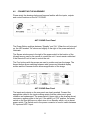
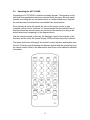
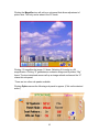
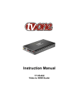
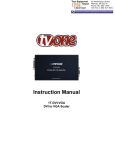
AV Toolbox
Instruction Manual
AVT-3190HD
PC/HDTV to Video
Scan Converter
2
Table Of Contents
1.0
Introduction
4
2.0
Specifications
6
3.0
Package Contents
7
4.0
Connecting the Hardware
8
5.0
Operating The Unit
9
6.0
Troubleshooting
17
7.0
Limited Warranty
18
8.0
Regulatory Compliance
19
9.0
Contact Information
19
3
1.0
INTRODUCTION
Thanks for purchasing this AVT-3190HD PC/HDTV to Video Scan Converter
product from AV Toolbox. The AVT-3190HD is designed to facilitate the
conversion of PC video or HDTV video to either NTSC or PAL video standard
outputs or component outputs. AV Toolbox offers a full line of high quality
Standards Converters, Up-Converters, Scan Converters, Distribution Amplifiers,
Routing Switchers, Time Base Correctors, PIP Display Devices, Quad Splitters
and Video Conditioners. RF Modulators, Digital Audio Converters, LCD
Monitors/Receivers and Multimedia Cables round out the product offerings.
1.1
Liability Statement
Every effort has been made to ensure that this product is free of errors. AV
Toolbox cannot be held liable for the use of this hardware or any direct or indirect
consequential damages arising from its use. It is the responsibility of the user of
the hardware to check that it is suitable for his/her requirements and that it is
installed correctly. All rights reserved. No parts of this manual may be
reproduced or transmitted by any form or means electronic or mechanical,
including photocopying, recording or by any information storage or retrieval
system without the written consent of the publisher.
AV Toolbox reserves the right to revise any of its hardware and software
following its policy to modify and/or improve its products where necessary or
desirable. This statement does not affect the legal rights of the user in any way.
All third party trademarks and copyrights are recognised. The AV Toolbox Logo,
TV One Logo, TV One-Task and CORIO are the registered Trademarks of TV
One. All other trademarks are the property of their respective holders.
4
1.2
FEATURES
The AVT-3190HD Scan Converter has many features that enable it to
perform in a superior manner. Among those features you will find:
•
•
•
•
•
•
•
•
•
•
•
•
Switchable PC or HDTV Inputs
NTSC or PAL Outputs, Composite, S-Video or Component (YCbCr)
Supports PC Inputs up to UXGA (1600x1200@60Hz)
Supports VGA Refresh Rates to 140Hz
Supports HDTV Inputs up to 1080i
Loop Thru Inputs––Both PC and HDTV
Adjustable Image Scaling: Pan, Position and Zoom
2D Flicker Filter
Aspect Ratio Adjustment
Test Functions: Overscan, Freeze, Test Pattern and Magnifier
Remote Control with OSD (On Screen Display)
RS-232 Control is Fully Supported
5
2.0 SPECIFICATIONS
Video Input Connectors
HDTV Video
PC
Video Output Connectors
Composite
S-Video
Component
HDTV Video
PC
Input Signal Characteristics
HDTV Inputs Resolution Supported
PC Resolutions Supported
Output Signal Characteristics
Composite, S-Video
Component
Control Methods
Local
Remote
Mechanical
Size (H-W-D)
Weight (Net)
Warranty
Limited Warranty
Power Requirements
External AC Adaptor
Regulatory Approvals
AVT-3190
AC Power Adaptor
Accessories Included
3x RCA Female (Loops to Output)
1x HD-15 Female (Loops to Output)
1x RCA Female
4-pin Mini-DIN Female
3x RCA Female
3x RCA Female (Looping From Input)
1x HD-15 Female (Looping From Input)
4801, 480p, 576i, 576p, 720p, 1080i
VGA, SVGA, XGA, SXGA, UXGA
NTSC or PAL, Interlaced
YCbCr
Push buttons on unit + OSD
IR Remote Control w/OSD + RS-232
2”x8”x6” (50mmx204mmx155mm)
2.2 Lbs (1kg)
1 Year, Parts and Labor
5 VDC/2A US, UK or EURO AC Plug
FCC, CE
UL, CE, CSA
1x AC Power Adapter
1x HD-15 to HD-15 VGA Cable
1x 3 RCA to 3 RCA Cable
1x RCA to RCA Component Cable
1x S-Video to S-Video Cable
1x IR Remote Control
1x Application Software CD
1x Instruction Manual
6
3.0
CHECKING PACKAGE CONTENTS
Before attempting to use this unit, please check the packaging and make certain
the following items are contained in the shipping carton:
•
•
•
•
•
•
•
•
•
1x AVT-3190HD Scan Converter
1x AC Power Adapter
1x HD-15 to HD-15 VGA Cable
1x 3 RCA to 3 RCA Cable
1x RCA to RCA Component Cable
1x S-Video to S-Video Cable
1x IR Remote Control
1x Applications Software CD
1x Operations Manual
Note: Please retain the original packing material should the need ever arise to
return the unit. If you find any items are missing, contact your reseller or AV
Toolbox immediately. Have the Model Number, Serial Number and Invoice
available for reference when you call.
7
4.0
CONNECTING THE HARDWARE
Please study the drawings below and become familiar with the inputs, outputs
and control locations on the AVT-3190HD.
AVT-3190HD Front Panel
The Power Button switches between “Standby” and “On”. When the unit is turned
on, the LED marked “On” above and slightly to the right of the power switch will
illuminate.
The Square window area to the right of the power switch is the location of the
Infrared sensor used by the remote to control the unit. It must remain unblocked
if the Remote IR unit is used to control the unit.
The Four buttons with the arrows are used to position and pan the image. The
Aspect button allows switching between wide screen and standard display
modes and the Overscan button allows magnification of the image.
AVT-3190HD Rear Panel
The inputs and outputs on the rear panel are clearly marked. Connect the
appropriate cables to the inputs making certain that the cables are in good
condition and undamaged. The power switch (Upper right on the drawing above)
removes or applies power to the unit. If the switch is in “Off” position, the power
switch on the front will have no effect since it is a Standby switch, not an actual
power switch. The Switch next to the power connector is used to switch between
PC input and HDTV input.
8
5.0
Operating the AVT-3190HD
Operating the AVT-3190HD is intuitive and easily learned. The operation at the
unit itself is accomplished via buttons mounted within the case. Although easily
learned, controlling the unit via these buttons is a rather limited way to operate
the unit because all functions are not available from these buttons.
Since virtually all users will operate the unit via the remote control to gain
complete control over its functions, it is recommended that you take the time to
discover where the various buttons are located on the remote by looking at the
actual remote and comparing it to the diagram above.
Like the manual controls on the unit, the labeling is clear for the majority of the
functions and the unit’s On Screen Display (OSD) will help clarify any confusion.
The pages that follow will magnify the remote’s control sections and explain each
function. Study the overall drawing and become familiar with the general layout of
the remote control. Refer to the descriptions that follow in this manual for detailed
information.
9
OUTPUT: Toggles between
Composite, S-Video and
Component Outputs
POWER: Switches
between “On” and
“Standby”
OVERSCAN: Toggles
Between over scanned
and under scanned
normal image.
FREEZE: Causes the
image being displayed to
freeze.
BUTTONS 1-9:
When the Zoom
button is pressed, the
picture is divided into
nine zones. Pressing
one of the numbered
buttons selects the
portion of the image
(the zone) you want
to enlarge.
ZOOM: Press the Zoom
button to enlarge a section
of the picture. Press it again
to return to normal image
size.
10
The Four Buttons shown below––Zoom, Aspect, Pos/Pan and Size/Exp––
control picture manipulations and the arrowed buttons work in conjunction with
these four buttons to do the actual manipulations. The Default Button (in the
middle of the arrow button matrix) returns the following parameters to factory
presets: Zoom, Position, Size and Picture Adjustments. Descriptions of the
Zoom, Aspect, Pos/Pan and Size/Exp functions are shown below.
ZOOM: As explained above,
this Button places the unit in
the Zoom mode and the
numbered buttons select the
portion of the image to be
zoomed. Once selected, the
arrowed buttons allow
zooming or movement across
the selected image.
ASPECT: This button toggles
three modes. Full is the regular
4:3 aspect mode. The second
toggle activates the Pan and
Scan mode wherein you can
adjust the image horizontally and
vertically. The final toggle
activates the letterbox mode.
POS/PAN: If the unit is in
underscan mode, pressing
this button allows the user to
position the under-scanned
image anywhere on the
raster using the arrow
buttons. If the unit is in the
overscan mode, pressing
this button allows the user to
pan the over-scanned image
using the arrow buttons
SIZE/EXP: When in the
underscan mode, pressing
this button allows the arrow
keys to expand or shrink the
image within the monitor’s
raster. If the system is in
overscan mode, the arrow
buttons set the degree of
overscan.
11
Along the right side and bottom of the remote control there are several control
buttons. The functions are:
CONTRAST, BRIGHTNESS,
COLOR & SHARP: These buttons,
allow adjustments to be made to the
labeled signal parameters. Pressing
a button causes the arrow buttons to
become active and those buttons are
used to make the actual adjustments.
V-RESET: Restores Factory default
settings to the Contrast, Brightness,
Color and Sharpness parameters.
NTSC/PAL: Selects the television
standard to use on the unit’s output.
SYS-RESET: Restores Factory
Presets to all parameters. (Overscan,
NTSC, 4:3 Aspect, Signal
Parameters & CV/SV Output.)
COLORBAR: Causes an internally
generated color bar signal to appear
on the unit’s outputs.
12
5.1 RS-232 Operation
Software is included to allow control of the AVT-3190HD via a computer. The
operation under RS-232 control is explained below.
5.1.1 Installation of the Software (Windows 98/ME/2000/XP)
• Place CD in appropriate drive and execute the setup.exe function from the CD.
(The computer will probably update some files causing the need to reboot after
the initial setup has finished. If this happens, reboot and run setup a second
time.)
• Once fully installed, click the taskbar menu (Start>Programs>Scan Converter)
to start the RS-232 software.
5.2 Operation Under Control of RS-232 Software
A main panel will appear containing 19 icons that provide the control functions of
the unit (except icons 16 through 19). Click the icon to perform the function.
Refer to the list of numbers on the next page to learn the function of the icons.
1
2
3
4
5
6
7
8
16
17
18
19
9
10
11
12
13
14 (Above)
15 (Below)
13
Icon Number
1
2
3
4
5
6
7
8
9
10
11
12
13
14
15
16
17
18
19
Meaning
Connection Status - If grey, there is no connection
Prompt Text
Power On Indicator
System Reset
Zoom
Magnifier
Over/Under Scan
Option
Aspect
Pan/Position
Expand/Size
Output Format
Screen Freeze
Video Settings
RS-232 Com Port in use
Close
Minimize
System Tray
About
Selecting Zoom will cause a sub menu to appear where the actual adjustments
are made. The functionality is just like the remote control for the sub-panel
wherein the arrows and number matrix control the same things that the remote
control did. (The upward facing arrow at the lower right returns you to the main
menu.)
14
Selecting Position/Pan or Size/Expand will cause a sub menu to appear where
the actual adjustments are made. The functionality is just like the remote control
for the sub-panel wherein the arrows control the same things that the remote
control did. (The upward facing arrow at the lower right returns you to the main
menu.)
Selecting Video Settings on the main menu will call up another sub-panel where
the actual adjustment can be made. Clicking the “R” icon on this panel resets
these settings to Factory Default. Again, the upward facing arrow at the lower
right returns you to the main menu.
15
Clicking the Magnifier icon will call up a sub-panel that allows adjustment of
picture size. This only works when in the PC mode.
Clicking 1.5 magnifies the image 1.5 times. Selecting 2.0 results in a 2X
magnification. Clicking “S” generates an undersize image and B yields a ”Big”
frame. The two intertwined arrows call up an image refresh routine and the “X”
closes this sub-panel.
There are two other sub-panels available:
Clicking Option causes the following sub-panel to appear. (Click on the desired
action.)
16
Finally, the last sub-panel displays software and firmware information. Click the
About icon to call up this display:
Again, the upward facing arrow at the lower right returns you to the main menu.
5.3 Pinouts for RS-232 Cable
The connections for the RS-232 connectors are as follows:
AVT-3190 Connector Pinout
1, NC
2, TxD
3, RxD
4, NC
5, GND
6, NC
7, NC
8, NC
9, NC
PC Serial Connector Pinout
1, NC
2, RxD
3, TxD
4, NC
5, GND
6, NC
7, NC
8, NC
9, NC
6.0 Troubleshooting
Other than checking for faulty cables, the only common problem would be
choosing a wrong Output Setting. Make sure the AVT-3190HD is capable of
handling the resolution and refresh rate selected and make sure the output
format selected (Composite, S-Video or YCbCr) is correct for the type of cable
and connector being used at the output. Also make certain that you have
selected the correct television standard (NTSC or PAL).
After trying the above suggestions should the problem still persist, contact your
dealer for additional suggestions before contacting TV One. Should the dealer’s
technical personnel be unable to assist you, contact TV One via our support
17
website: http://tvone.crmdesk.com. Create a technical support request on the
site and our support team will respond within a short period of time.
7.0
LIMITED WARRANTY
LIMITED WARRANTY – With the exceptions noted in the next paragraph, AV
Toolbox warrants the original purchaser that the equipment it manufactures or
sells will be free from defects in materials and workmanship for a period of one
year from the date of purchase. Should this product, in AV Toolbox’s opinion,
prove defective within this warranty period, AV Toolbox, at its option, will repair or
replace this product without charge. Any defective parts replaced become the
property of AV Toolbox. This warranty does not apply to those products which
have been damaged due to accident, unauthorized alterations, improper repair,
modifications, inadequate maintenance and care, or use in any manner for which
the product was not originally intended.
Items integrated into AV Toolbox products that are made by other manufacturers,
notably computer hard drives and liquid crystal display panels, are limited to the
term of the warranty offered by the respective manufacturers. Such specific
warranties are available upon request to AV Toolbox.
If repairs are necessary under this warranty policy, the original purchaser must
obtain a Return Authorization Number from AV Toolbox and return the product to
a location designated by AV Toolbox, freight prepaid. After repairs are complete,
the product will be returned, freight prepaid.
LIMITATIONS - All products sold are "as is" and the above Limited Warranty is in
lieu of all other warranties for this product, expressed or implied, and is strictly
limited to two years from the date of purchase. AV Toolbox assumes no liability
to distributors, resellers or end-users or any third parties for any loss of use,
revenue or profit.
AV Toolbox makes no other representation of warranty as to fitness for the
purpose or merchantability or otherwise in respect of any of the products sold.
The liability of AV Toolbox with respect to any defective products will be limited to
the repair or replacement of such products. In no event shall AV Toolbox be
responsible or liable for any damage arising from the use of such defective
products whether such damages be direct, indirect, consequential or otherwise,
and whether such damages are incurred by the reseller, end-user or any third
party.
18
8.0 REGULATORY COMPLIANCE
This product complies with the relevant standards for CE and FCC approval.
The Power Adaptor/Supply has been tested for compliance with: UL, CSA and
CE standards.
9.0
CONTACT INFORMATION
Should you have questions or require assistance with this product in areas not
covered by this manual, please contact us at the location shown below:
AV Toolbox
1350 Jamike Drive
Erlanger, Ky, 41018
859.282.7303
19
AV Toolbox
1350 Jamike Drive
Erlanger, Ky, 41018
859.282.7303