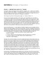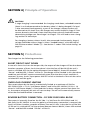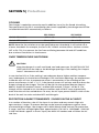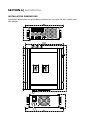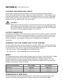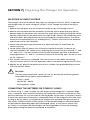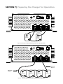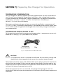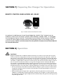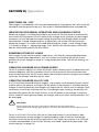
1
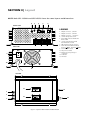
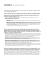
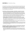
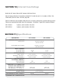
Owner's
Manual
Please read this
manual before
operating your
battery charger
Switch Mode,
Automatic, Lead
Acid Battery
Charger
MODELS:
SEC-1250UL
SEC-2425UL
Section 1 | Important Safety Precautions
The following safety symbols will be used in this manual to highlight safety
and information:
WARNING!
Indicates possibility of physical harm to the user in case of non-compliance.
!
CAUTION!
Indicates possibility of damage to the equipment in case of non-compliance.
i
INFO
Indicates useful supplemental information.
Hazardous conditions may result if the charger is not installed or operated correctly.
Please read the following instructions to prevent personal injury or damage to the
charger.
Battery Related
• To reduce the risk of battery explosion, follow these instructions and those marked on
the battery.
• Never smoke or allow an open spark or flame in the vicinity of the battery or the
engine.
• Charge only Lead Acid type of batteries (Flooded / Absorbed Glass Mat (AGM) / Gel
Cell). Do not charge other type of batteries like Nickel Cadmium (NiCad), Nickel-Metal
Hydride (Ni-MH), Dry-Cell etc. Other types of batteries might burst causing personal
injury.
• Never charge a frozen battery.
• Working in the vicinity of Lead Acid batteries is dangerous. Batteries generate explosive Hydrogen and Oxygen gases during normal operation. Take necessary safety
precautions when installing the charger near a battery or in a battery compartment
(Follow safety instructions given by the battery manufacturer).
• Never place the charger directly above or below the battery being charged; gases or
fluids from the battery will corrode and damage the charger. Locate the charger as far
away from the battery as DC cables permit. Do not install in the same compartment as
batteries.
• Use caution to reduce the risk of dropping a metal tool on the battery. It could spark
or short circuit the battery or other electrical parts and could cause an explosion.
Section 1 | Important Safety Precautions
• Remove metal items like rings, bracelets and watches when working with batteries.
The batteries can produce a short circuit current high enough to weld a ring or the
like to metal and thus cause a severe burn.
• If you need to remove a battery, always remove the ground terminal from the battery
first. Make sure that all the accessories are off so that you do not cause a spark.
Charger Related
• The maximum Ah capacities of the batteries must be limited as follows:
- SEC-1250UL: 500 Ah
- SEC-2425UL: 300 Ah
• Do not operate the charger in a closed-in area or restrict ventilation in any way.
Install in a well ventilated, cool, dry place.
• The charger must not be operated in a damp or wet environment. When mounting
in a boat, make sure it is not subjected to bilge water splash.
• Do not block the ventilation openings / openings for the cooling fan. There should
be at least 6 inches clearance all around the unit.
• Installation and wiring must comply with the local and the National Electrical Codes.
It is recommended that installation may be carried out by a certified electrician.
• Wrong installation on a boat may lead to corrosion of the boat. It is recommended
that installation on the boat must be carried out by a boat electrician.
• Disconnect the AC input power to the charger before connecting / disconnecting the
batteries or other DC loads or when working on the charger.
• Disconnect the AC input power before changing the setting of the Dip Switches.
• The chassis of the charger is connected to the earth ground pin of the power cord
plug. Ensure that the earth ground pin of AC receptacle feeding the charger is
connected to earth ground.
• Do not use an adapter. If a grounding type of receptacle is not available, do not use
this charger until proper outlet is installed by a qualified electrician.
• Do not operate the charger if the power cord is damaged.
Section 2 | Description & Features
SEC-1250UL (for 12V batteries) and SEC-2425UL (for 24V batteries) are high current, 3
Stage Chargers (also called I UOU) that deliver 50A and 25A respectively for almost 75%
to 80% of the charging cycle ensuring a very fast, safe and complete charging of Lead
Acid batteries. The nomenclature “ I UO U” is a DIN nomenclature and signifies the 3
charging stages – “I” for Bulk Charge Stage, “UO” Absorption / Over-charge Stage and
“U” for Float / Maintenance Stage (under DIN specification, voltage is designated “U”
and current is designated “I”. The subscript “O” in “UO” signifies over- charge).
Features
• State-of-the-art Switch Mode Technology for high efficiency, light-weight and quiet
operation.
• User configurable AC input voltage – 120 VAC or 230 VAC, 50 / 60 Hz
• Automatic operation for all types of Lead Acid Batteries - Flooded, AGM or Gel Cell
• User selectable 2 or 3-Stage automatic charging algorithm with timed Absorption
Stage and temperature compensation ensures rapid, safe and full return of capacity
for stand-alone and loaded batteries.
• Ability to reduce maximum charging current to approximately 1/2 of the rated capacity during “Half Power Mode”. This allows safe charging of lower capacity batteries.
• Includes a Battery Temperature Sensor allowing temperature compensated charging,
if required.
• 2 banks of batteries can be charged simultaneously without the use of an external
battery isolator. The charging current will be shared between the two banks depending upon the depth of discharge of the connected batteries.
• Voltmeter and Ammeter for monitoring
• Fan cooled - fan on/off based on output current.
• Protections against short circuit, over current, reverse battery connection and
over-temperature.
• Can be used as a power supply or as a DC UPS (Uninterruptible Power Supply)
when used in conjunction with a battery.
• Optional Remote LED Panel Model 900-RC with 10 Meters of wire for remote
ON/OFF control and indication of charging status.
• Safety certified and listed to UL Standard UL-1564
• EMI compliant to FCC Part 15(B), Class B
Maximum Ah Capacity Of Battery To Be Charged
If the chargers are used to charge very high capacity batteries, they will be forced to
supply their maximum rated charging current for longer time than the designed limit
and hence, the components will be overstressed and are likely to fail prematurely. To
prevent premature failure, the maximum Ah capacities of the batteries must be limited
as follows:
- SEC-1250UL: 500 Ah
- SEC-2425UL: 300 Ah
SECTION 3 | Layout
NOTE: Both SEC-1250UL and SEC-2425UL have the same layout and dimensions
4
5
6
7
8
OUTPUT SIDE
LEGEND
1. Output connector: +, Bank 1
2. Output connector: +, Bank 2
3. Output connector: –, Common
4. Jack for Temperature Sensor
5. Green LED: Indicates “Half Power
Mode” is ON
6. Jack for optional Remote LED
Panel Model No. 900-RC
7. DIP switches for mode selection
3
INPUT SIDE
2
1
8. Push Switch for Half Power Mode:
Pressed
ON; Released
OFF
9. Power ON/OFF switch
10. AC power cord inlet
11. Grille protected opening for
cooling fan
9
12. Voltmeter
13. Ammeter
10
11
TOP VIEW
12
11
3
2
1
13
10
Fig. 3.1 Layout of SEC-1250UL and SEC-2425UL
SECTION 4 | Principle of Operation
i
INFO
For complete understanding of working of battery chargers, understanding of
operation of Lead Acid batteries is desirable.
For detailed information on construction, working and application of batteries,
please refer to Application Note titled “Lead Acid Batteries – Construction and
Application” at the following link to Samlex America, Inc.
BATTERY CHARGER IS A CURRENT LIMITED DC POWER SUPPLY
The charger is a current limited DC power supply that converts 120 / 230 VAC, 50 / 60 Hz
to regulated DC voltages and limits the maximum output current as follows:
Constant
Voltage at
Absorption
Stage “U0”
Constant
Voltage at
Float Stage
“U”
Current Limit
Constant
Voltage at Bulk
Stage “I”
SEC-1250UL
50A
13.5 VDC
14.0 VDC or
14.4 VDC
13.5 VDC
SEC-2425UL
25A
27 VDC
28 .0 VDC or
28.8 VDC
27 VDC
Model No.
The specified output voltage of the charger during particular charging stage is held
constant till the current limit value is reached. When the battery or DC load tries to draw
current > the current limit value, the charger limits the current to the current limit value
and the output voltage of the charger drops and is no longer constant. When the charger is connected to a battery and is in current limit condition, the terminal voltage of
the charger will be clamped to the actual lower intrinsic terminal voltage of the battery
(assuming the charger is very close to the battery and there is no voltage drop in the
wires connection the charger to the batteries).
BATTERY IMPEDANCE AND CHARGING CURRENT
The internal impedance of a healthy battery is very low - in tens of milli Ohms (The
impedance is higher in discharged condition due to Lead Sulfate formation and reduces
when the battery is fully charged – Lead Sulfate gets fully converted to Lead and Lead
Dioxide). Average impedance may be assumed as 20 milli Ohm or 0.02 Ohm
When the charger is delivering a constant voltage (is not in current limit condition), the
charging current drawn by the battery can be roughly calculated as follows:
Charging current = (Charger Voltage - Intrinsic battery voltage) ÷ Internal resistance (0.02 Ohm)
SECTION 4 | Principle of Operation
For example, when SEC-1250UL is in the Bulk Charge Stage 1, its output voltage is set
at 13.5 VDC. When a battery discharged to say 10.5V is charged, it will try to draw very
large current = (13.5V - 10.5V) ÷ Internal resistance (0.02 Ω) = 150A. SEC-1250UL will,
however, limit this current to 50A.
CHARGING STAGES
The battery is charged in 3 stages:
• STAGE 1 -BULK STAGE (“I” Phase),
• STAGE 2 - ABSORPTION STAGE (“UO” Phase) and
• STAGE 3 - FLOAT STAGE (“U” Phase)
The 3 charging stages and associated Charging Curves for SEC-1250UL are given at Figure 4.1 and for SEC-2425UL at Fig. 4.2
Stage 1
“I Phase”
15
Stage 2*
“Uo Phase”
Stage 3
“U Phase”
14.4V
14
13
13.5V
D1
12
11
10
A1
B1
C1
B2
C2
Voltage
curve
E1
D2
9
55
50
45
8
50A
7
A2
40
6
35
5
30
25
20
15
10
5
0
4
3
80% of
current
capacity
of charger
(40 Amps)
2
1
Current
curve
10% of
current
capacity
of charger
(5A ± 0.5A)
E2
0
AMPS VOLTS
Time, Hours
Figure 4.1 Charging Curve - SEC-1250UL
Fig xxx - SEC-1250UL Charging Curves (Absorption 14.4V, Float 13.5V)
* Stage 2 time for 4 or 8 hours.
SECTION 4 | Principle of Operation
30
Étape 1
Étape 2*
Étape 3
“Phase I”
“La Phase Uo”
“La Phase U”
28.8V
28
26
27V
24
22
20
A1
18
27.5
25.0
22.5
16
25A
14
A2
20.0
12
17.5
10
15.0
8
12.5
6
10.0
7.5
4
5.0
2
2.5
0
B1
C1
B2
C2
80% de
la capacité
actuelle du
chargeur
(20 ampères)
D1
Voltage
curve
E1
D2
10% de la
capacité
actuelle
du chargeur
(3A ± 0,5A)
E2
0
AMPS VOLTS
Temps, Heures
* Étape 2 temps de 4 ou 8 heures.
Fig. 4.2 Charging Curve for SEC-2425UL
i
INFO
Fig xxx - SEC-2425UL
Charging Curves (Absorption 28.8V, Float 27V)
Please note the following important information related to the Charging Curves
shown in Figs 4.1 and 4.2 above:
1.1 Terminal Voltage reading on no load and on load: The output terminals of the
charger consist of one common Negative terminal (3) and two Red Positive terminals
(1, 2) for charging two banks of batteries. Each of the two Positive terminals of the
two banks has Schottky Diode in series for isolation. These isolating diodes have a
current dependent forward voltage drop Vf ranging from 0.2 to 0.3V (at 0.1A) to
0.6V (at 50A). In addition, there will be additional forward drop Vb across the bulk
resistance of the diode and this drop will also increase with increase in charging
current. Please note that the forward voltage drops Vf and Vb occur only when current flows through the diode.
1.2 The Float and Absorption voltages are tightly regulated before the isolating
diodes. However, the voltages available at the terminals of the two banks will vary
with the value of the charging current because of the current dependent forward
voltage drop Vf and bulk resistance drop Vb. The Float Voltage before the diodes is,
SECTION 4 | Principle of Operation
therefore, set 0.2 to 0.3V higher to compensate for the forward drops during float
condition when the charging current would have dropped to less than 1A. Hence,
the output voltage at the terminals of the two banks at no load (nothing connected
to the terminals of the banks) will read 0.2 to 0.3V higher because there is no forward voltage drop as there is no current flow through the diodes. The voltages are
specified with respect to charging / load current as follows:
Absorption Stage (“UO” Phase) of 14.4 / 14V for SEC-1250UL
At 5A +/- 0.5A
Absorption Stage (“UO” Phase) of 28.8 / 28V for SEC-2425UL
At 3A +/- 0.5A
Float Stage (“U” Phase) of 13.5V for SEC-1250UL
At 0.1A
Float Stage (“U” Phase) of 13.5V for SEC-2425UL
At 0.1A
1.3 Please also note that the output voltage at the two banks may differ between
0.2 to 0.6V depending upon the different values of the charging current being delivered through each as a result of different values of voltage drops Vf and Vb.
2.1 Standard Temperature Conditions: The charging voltages shown pertain to battery electrolyte temperature of 77°F (25°C)
3.1 Charger / Battery Voltage / Current Values: When the battery is connected to
the charger and the charger is in ON condition, the voltage at the common charger
/ battery terminals will be the actual battery terminal voltage corresponding to its
state of charge ONLY when the charger is in “current limit condition” and is supplying 50A for SEC-1250UL and 25A for SEC-2425UL. When the charger is NOT in
“current limit” condition and is supplying < 50A for SEC-1250UL or < 25A for
SEC-2425A, its terminal voltage will be nearly regulated and will be nearly equal to
the set Bulk / Float Voltage of 13.5V for SEC-1250UL (27V for SEC-2425UL) or nearly
equal to the Absorption Voltage of 14.4 / 14V for SEC-1250UL (28.8V / 28V for SEC2425UL). Under these conditions, the battery terminal voltage will also be at 13.5
(27V) or 14.4 / 14V (28.8V / 28V) although the actual intrinsic terminal voltage of the
battery corresponding to its State of Charge at that point of time will be lower.
3.2 The voltage curve shows the voltage at the charger output terminals, which will
be the same as the voltage at the battery terminals (assuming that there is no voltage drop along the wires connecting the charger to the batteries)
3.3. The Current Curve shows the current being drawn by the battery
SECTION 4 | Principle of Operation
STAGE 1- BULK CHARGE STAGE (“I” PHASE)
In this stage SEC-1250UL outputs voltage of 13.5 VDC and SEC-2425A outputs 27V.
The following explanation is for SEC-1250UL. Explanation for SEC-2415UL will be
same but the voltage values will be 2 times and current values will be half as compared
to SEC-1250UL.
NOTE: For explanation purpose, it is assumed that the battery is deeply discharged
to around 10.5 / 21V when charging is initiated.
When the charger is switched on, the battery will try to draw very large current =
(13.5V- 10.5V) ÷ Internal resistance (0.02 Ω) = 150A which will be much higher than the
current limit value of 50A. The charger will enter current limit condition (point A2),
its internal voltage will try to drop but will be clamped to the terminal voltage of the
battery i.e. 10.5V (point A1). The battery starts charging at constant current of 50A (Section A2-B2) and its intrinsic voltage starts rising almost linearly (Section A1-B1). When
its intrinsic voltage approaches 13.5V, the current drawn by the battery will reduce to
< 50A. At this point (B2), the charger will exit current limit and will output a constant
voltage of 13.5V (point B1). As the battery charges further under constant voltage of
13.5V (Section B1 – C1), its intrinsic voltage rises further and its current starts to taper
down (Section B2 – C2). The current tapers down because the intrinsic battery voltage is
rising and the differential voltage between 13.5V of the charger and intrinsic voltage of
the battery is reducing thereby, lesser current is driven into the battery. Tapering charge
is provided at this transition to reduce surface charge effect to ensure that the charge
slowly diffuses to the internal thickness of the plates and prevents overcharging. When
the charging current tapers down to 80% of the rated capacity of the charger (40A for
SEC-1250UL and 20A for SEC-2425UL) at point “B2”, the charger transitions to the next
Stage 2 - Absorption Boost Stage (“UO” Phase)
Charging Characteristics During This Stage Are As Follows:
• Battery voltage rises slowly and almost linearly (it will start rising sharply at
the beginning of the next Absorption Stage 2).
• The entire charging current is used to convert Lead Sulfate to Sponge Lead at
the Negative plates and to Lead Dioxide at the Positive plates.
• There is no gassing and the charging efficiency is high - around 91%.
• The restored capacity in this stage is inversely proportional to the charging rate
(due to Peukert Effect). This means that as the charging rate is increased, the
capacity restored reduces. This stage restores 60% of capacity at charging rate
of C/5, 70% to 75% capacity at charging rate of C/10 and 85% to 90% of
capacity at charging rate of C/20
• Red LED marked “I Phase” will be lit on the optional Remote Control
Model 900-RC
SECTION 4 | Principle of Operation
STAGE 2 – ABSORPTION STAGE (“U0” PHASE)
During this stage, the charger outputs constant voltage of 14V / 14.4V for SEC-1250UL
and 28V / 28.8V for SEC-2440UL. As charging proceeds, there is a fairly sharp rise in the
battery voltage as gassing starts. Gassing and fast rise of battery voltage continues to
restore the balance of the capacity till charging is completed.
The Charger Transitions To Absorption Stage (“UO” Phase) At Point “C”.
As soon as the charger transitions to this stage, a user selectable 4 Hr / 8 Hr Timer is
started with the help of DIP Switches (7) (See page 22 under “Selecting time for stage
2 - Absorption Stage”). This Timer decides the maximum duration of operation in this
stage and subsequent transition to the final constant voltage Float Stage 3 at point “E”.
The duration of operation in this stage is also determined by another condition where
the transition to the next Float Stage at point “E” occurs when the charging current
reduces to 10% or the rated capacity i.e. 5A +/- 0.5A for SEC-1250UL and 3A +/- 0.5A for
SEC-1225UL. The condition, which occurs earlier, controls the transition At the transition point “C”, the charger will output a higher constant voltage, which is
above the Gassing Voltage to ensure that the battery is further, charged to full capacity
without overcharging. The value of this voltage will depend upon the type of battery or
charging stages selected (The type of battery and charging stages are selected with the
help of DIP Switches (7) - See Section 7 under “DIP Switch Setting” on page 21):
• 14.4V (SEC-1250UL) or 28.8V (SEC-2425UL) when Flooded / AGM
battery is selected
• 14V (SEC-1250UL) or 28V (SEC-2425UL) when Gel Cell battery is selected
• 13.5V (SEC-1250UL) or 27V (SEC-2425UL) when loaded battery is
selected (2 stage charging)
However, this constant voltage is not seen immediately because the charger enters current limit as soon as it enters point (C2). As the charger voltage has been increased, the
battery will try to draw higher value of current which will be equal to the difference
between this higher voltage and the actual intrinsic voltage of the battery divided by
the internal resistance of the battery (.02 Ohm). The value of this current at the transition point (C2) will be higher than the current limit value forcing the charger to enter
current limit condition once again. As the charger is in current limit condition, it does
not regulate its output voltage. The voltage at the charger terminals is the actual internal battery voltage at that point (C1). Once again, the battery starts charging further at
the maximum rated constant current of 50A for SEC-1250UL / 25A for SEC-2425UL (C2 to
D2). The battery voltage also starts rising further (C1 to D1).
At point (D2), the charging current reduces to less than the current limit value of 50A
for SEC-1250UL / 25A for SEC-2425UL and the charger now exits current limited constant
current mode and enters constant voltage mode of 14V / 14.4V for SEC-1250UL and
28V / 28.8V for SEC-2440UL (point D1). (Please note that the voltage of 14V / 14.4V or
SECTION 4 | Principle of Operation
28V / 28.8V at both the charger and battery terminals is the constant Absorption Voltage being put out by the charger. The intrinsic voltage of the battery is still lower than
this voltage as the battery is still not fully charged at this transition). As the intrinsic
voltage of the battery rises further, the charging current starts tapering down (section
D2 to E2). Tapering charge is provided at this transition to reduce surface charge effect
to ensure that the charge slowly diffuses to the internal thickness of the plates and
prevents overcharging.
When the 4 Hr / 8 Hr Timer runs out or when the charging current tapers down to 10%
of the rated capacity of the charger (5A +/- 0.5A for SEC-1250UL and 3A +/- 0.5A for SEC2425UL) at point “E2” (whichever is earlier), the charger transitions to the next Stage 3
- Constant Voltage, Float or Maintenance Charge Stage (“U” Phase)
NOTE: The threshold of current for change-over between the Constant Overcharge Voltage, Timed Voltage Absorption / Boost Stage (“U0” Phase) & the Float / Maintenance
Charge Mode (“U” Phase) are different as follows:
From “Uo” Phase to “U” Phase
From “U” Phase to “Uo” Phase
SEC-1250UL
5A +/- 0.5A
10A +/- 1A
SEC-2425UL
3A +/- 0.5A
6A +/- 1A
Charging Characteristics During This Stage Are As Follows:
• The Absorption Stage (“UO” Phase) feeds additional 35% to 55% of the capacity that
adds up to a total charged capacity of around 115% to take care of around 15% loss
of charging efficiency.
• Orange LED marked “UO” Phase on the optional Remote Control 900-RC will be lit
STAGE 3 - CONSTANT VOLTAGE, FLOAT OR MAINTENANCE
CHARGE STAGE (U PHASE)
During this mode, the charger outputs a constant voltage "U" = 13.5V (SEC-1250UL) or
27V (SEC- 2425UL). This helps in maintaining full capacity of the battery and also provides replacement charge to overcome self discharge of the battery. The battery
can remain connected in this stage indefinitely without the risk of discharging.
Charging characteristics during this stage are as follows:
Green LED marked Float Stage (“U” Phase) on the optional Remote Control
900-RC will be lit.
SECTION 4 | Principle of Operation
!
CAUTION!
3 stage charging is recommended for charging stand-alone, unloaded batteries
(there is no load connected to the battery when it is being charged). If a load
is also connected simultaneously, a part of the charger’s output current will
be diverted to this load. Thus, the charger may remain locked in Stage 2 if the
current drawn by the load is more than the preset value of threshold current
determining change over from Stage 2 to Stage 3 .This will lead to over- charging and loss of electrolyte.
For charging a battery when a load is also connected simultaneously, Stage 2
voltage should be same as Stage 3. Select “Loaded Battery” with the help of
DIP Switches marked “Mode” (7) - See Section 7 under “DIP Switch Setting” on
page 21.
SECTION 5 | Protections
The charger has the following protections:
SHORT CIRCUIT SHUT DOWN
In case of a short circuit on the output side, the output of the charger will be shut down. Another symptom of short circuit shut down is that the fan will be ON till the unit is
reset or switched OFF. On the optional Remote Control 900-RC, Green LED marked
"Power" and Red LED "I Phase" will be lit. The charger will be latched in this shut down
condition and will NOT recover automatically even after the short circuit condition is
removed. To reset, the AC input power ON/ OFF switch at the back of the unit has to be
switched OFF and ON again. OVER LOAD CURRENT LIMITING
The current drawn by the load is automatically limited to a maximum of 50A for
SEC-1250UL (25A +/- 1A in “Half Power Mode”) and 2A for SEC-2425UL (12.5A +/- 1A
when in “Half Power Mode”). If the load tries to draw a higher current than these limits, the output voltage of the unit will start to drop. The unit will automatically recover
when the overload condition is removed.
REVERSE BATTERY CONNECTION – DC Side Fuses Will Blow
The output is internally fused on the DC side - 2 x 30A fuses for SEC-1250UL and 2 X
20A fuses for SEC-2425UL. In case, the polarity of the battery connection is reversed, the
fuse(s) will blow. Another symptom of blown fuse on DC side is that the fan will be ON
till the unit is switched OFF. On the optional Remote Control 900-RC, Green LED marked
"Power" and Red LED marked "I Phase" will be lit.
SECTION 5 | Protections
COOLING
The charger is cooled by convection and in addition, has a fan for forced air-cooling.
The operation of the fan is controlled by the current supplied by the charger and will be
switched ON and OFF automatically as follows:
SEC-1250UL
SEC-2425UL
Switch ON current
10A +/- 1A
6A +/- 1A
Switch OFF current
5A +/- 0.5A
3A +/- 0.5A
NOTE: Once the fan switches on at the specified current threshold, it will switch off at
a lower threshold. For example, the fan in SEC-1250UL switches ON at 10A but switches
OFF at 5A. This is to prevent the fan from oscillating between ON and OFF conditions
due to minor fluctuations in load current
OVER TEMPERATURE SHUTDOWN
!
CAUTION!
Keep the charger in a well ventilated, cool and open area. Do not block the vent holes on the sides or the discharge openings of the cooling fan. Keep at
least 6” clearance on all sides
In case the fan fails or if the cooling is not adequate due to higher ambient temperature, inadequate air circulation or blockage of air ventilation openings, the temperature
inside the unit will rise. A temperature sensor is mounted on in the windings of the
power transformer. At 105° C +/- 5° C the thermal sensor will activate and shut down the
output voltage of the charger. The fan will be ON. On the optional Remote Control
900-RC, Green LED marked "Power" and Red LED marked "I Phase" will be lit. The
charger will be latched in this shut down condition and will NOT reset automatically
even after the unit has cooled down. To reset, the AC input power ON/OFF switch at the
back of the unit has to be switched OFF and ON again.
Protection Against Transients / Surges In The Ac Input
In a number of locations, the AC line input is not clean and may contain high voltage transients / surges. To prevent damage to the internal components against these
unwanted high voltages, the charger uses a MOV (Metal Oxide Varistor) for protection.
If surge / transient voltage higher than approximately 170 VAC in 120V Mode / 340 VAC
in 230 VAC Mode appear in the AC input, the MOV will conduct and will blow the AC
side fuse.
SECTION 6 | Installation
INSTALLATION DIMENSIONS
Installation dimensions are given below. Dimensions are same for SEC-1250UL and
SEC-2425UL.
SECTION 6 | Installation
LOCATION, MOUNTING AND SAFETY
The charger is required to be installed in a safe, well ventilated and dry location.
Please see the details given under “Important Safety Precautions”. The charger can be
mounted horizontally or vertically. When mounting vertically on a wall or a bulkhead,
please ensure that the axis of the fan rotor is horizontal i.e. the fan exhaust opening
should face left or right but NOT face up or down.
WARNING!
Mounting the unit vertically on a vertical surface with the fan opening facing
up or down is NOT allowed for safety. This is to prevent falling of objects into
the unit through the fan grille when the fan opening faces up. If fan opening
faces down, hot damaged components may fall out.
OUTPUT CONNECTORS
Connectors with tubular, screw down type of terminals are used for output connection.
The diameter of the tubular hole of the connector is 8 mm (0.31 inches). Two positive
output connectors (1, 2) are provided for connecting to the Positive terminals of the 2
banks of batteries. One common connector (3) is provided for the Negative
connection.
TERMINAL LUGS FOR CONNECTION TO THE CHARGER
For firm connection when using stranded wire, crimp / solder “pin” style terminal lugs
on the charger end of the DC wires used for connecting to the battery / other DC loads.
3 pieces of “pin” style terminal lugs have been provided as follows:
• For SEC-1250UL Will accommodate up to AWG #4 wire
• For SEC-2425UL Will accommodate up to AWG #8 wire
WIRES
To avoid polarity errors and possible damage, never use wires of only one color. Use Red
insulated wire(s) for Positive connection(s) and Black for Negative connection(s).
Recommended DC wire sizes are given below (Based on a voltage drop of 2%). The
length in feet is the length of the pair of the positive and negative DC wires from the
charger to the battery / other DC loads.
Distance From Battery
Up to 6 ft.
6 to 10 ft
10 to 20 ft.
SEC-1250UL
SEC-2425UL
AWG #6
AWG #10
AWG #4
AWG #8
AWG #1/0
AWG #6
TERMINATION OF WIRE ENDS
For firm connection when using stranded wire, wire ends for the connection to the
charger should be terminated with pin types of lugs that have been provided.
SECTION 7 | Preparing the Charger for Operation
SELECTING AC INPUT VOLTAGE
The charger is pre-set to operate from input AC voltage of 120 VAC, 60 Hz. To operate
the charger from AC input voltage of 230 VAC, 50 Hz, change the internal setting as
follows:
1. Remove the side plate that has the power cord entry by unscrewing 4 screws
2. Remove the Voltmeter and the Ammeter on the top central plate by prying up the
bottom edges of the meters with a broad, flat screw driver and by pushing the meters
up from the bottom of the plate (these are snap fitted). Remove the connecting wires
and mark them. Note the polarity for connecting back in proper polarity. The meter
terminals are marked Positive (+) and Negative (-). Thicker wires are for the Ammeter
and thinner are for the Voltmeter 3. Gently slide the center top cover plate out. Note and mark its orientation for
correct re-fitting
4. Locate Yellow loop of jumper wire with quick female disconnect. In the pre-set
120 VAC condition, this jumper wire is shorting the male vertical pins marked “C” and
“D” and “115V”. Pull any one end of this female disconnect upwards to disconnect
shorting between “C” and “D”. Insulate this end with insulating tape. The unit is now
set for “230 VAC”
5. The 120 VAC version has a soldered 12A fuse on the AC side. When converting
120 VAC version unit for 230 VAC operation, there is no need to replace the 12A fuse
6. Replace the AC plug of the power cord with a suitable 3 pin grounded plug to mate
with the 230 VAC outlet.
!
CAUTION!
The new plug should have 3 poles i.e. Line (L), Neutral (N) and Earth ground.
Color code for the power cord conductors is:
- Line (L) - Black
- Neutral (N) - White
- Earth ground - Green
CONNECTING THE BATTERIES OR OTHER DC LOADS
As shown in Fig. 7.1 and 7.2 (page 19), the output of the charger has a common Negative (-) connector and 2 Positive connectors for connection of 2 banks of batteries. Each
Positive connector has its own internal isolating diode, which works as a battery isolator.
If more than one bank of batteries is connected, these will be charged at the same time
as long as the AC power is available to the charger (the maximum charging current of
50A of SEC-1250UL and 25A of SEC-2425UL will be shared among the connected banks
of the batteries depending upon their discharged states). In case the AC power fails
or if there is no output from the charger, the isolating diodes will prevent charging /
discharging among the batteries connected to the banks.
SECTION 7 | Preparing the Charger for Operation
Auxilary /
House
Battery
Starter
Battery
Fig 7.1 Connecting 2 separate battery systems to 2 separate banks
Positive
Wire “A”
Negative
Wire “B”
Battery 4
Battery 3
Battery 2
Fig. 7.2 Connecting bank of paralleled batteries to single bank
Battery 1
SECTION 7 | Preparing the Charger for Operation
In a single battery bank, two or more batteries may be connected in parallel to increase
their AH capacity. These will be discharged and charged as a single battery bank. In this
case, the paralleled bank of multiple batteries is to be considered as a single bank and
connected to any one of the 2 banks of the charger as shown in Fig. 7.2 for bank of 4
batteries. For proper charging of all the batteries, please ensure that the Positive wire
“A” from the charger is connected to the Positive terminal of the first battery (Battery
1) and the Negative wire “B” is connected to the Negative terminal of the last battery
(Battery 4). This will ensure the following:
• Resistance of the interconnecting cables will be balanced and the individual batteries
will see the same series resistance
• All the individual batteries will be charged at the same charging current and thus will
be charged to the same state of charge
• None of the batteries will see an over-charge condition
When connecting a single battery or other single DC load, it can be connected to the
common Negative and any one of the 2 Positive terminals as in Fig. 7.1.
CHARGING MORE THAN ONE BANK OF BATTERIES
!
CAUTION!
When charging more than one bank of batteries at the same time using 3 Stage
Charging, ensure that the batteries in the banks are in a similar discharged condition. If one bank is completely discharged and another is almost fully charged,
the bank that is fully charged will be subjected to over charge condition during
the time when the charger remains in Stage 2 (“Uo” Phase) for charging the
completely discharged bank.
If 2 banks of batteries are required to be charged and they are at different
discharged conditions, select “Loaded Battery” (2 Stage Charging) with the help
of switches S1 and S2 of the set of 4 DIP Switches (both S1 & S2 in off condition)
- See under heading “Dip Switch Setting” on page 21.
SELECTING TYPE OF BATTERY AND CHARGING STAGES
Stage 3 Float Stage (“U” Phase) voltage and Stage 2 Absorption Stage (“Uo” Phase) voltage are different for different types of Lead Acid Batteries.
3 Stage charging (Stages 1, 2 and 3) is recommended when charging stand alone, unloaded battery (The battery has no load connected to it when it is being charged).
When the charger is used to charge a battery and simultaneously supply an external
load, the voltage level of Stage 2 is required to be set to the same level as the voltage of
Stage 3 to prevent over-charging. Effectively, the battery will be charged in 2 stages only
SECTION 7 | Preparing the Charger for Operation
- Stage 1 and Stage 3. This also applies when two banks of batteries are being charged
simultaneously and the batteries in the two banks are in a dissimilar state of discharge.
A pair of switches S1 & S2 out of a set of 4 DIP Switches has been provided for selecting
the battery type and for modifying the Stage 2 Absorption Stage when charging loaded
batteries / two banks of batteries with different discharged states. The following selections can be made with the help of the DIP Switches S1 and S2:
!
CAUTION!
Do not change the DIP Switch setting when the charger is operating. Always
change the DIP Switch setting when the charger is OFF, i.e. after disconnecting
the charger from the AC input power).
NOTE: The voltages are for battery temperature of 77ºF / 25ºC.
DIP SWITCH SETTING FOR SEC-1250UL Battery
Type
Charging
Stages
14.4V*
Flooded /
AGM*
3 Stages
(Stages 1, 2, 3)
13.5V
14.0V
Gel Cell
3 Stages
(Stages 1, 2, 3)
13.5V
Disabled
Battery with
Load
2 Stages
(Stages 1, 3)
S1
S2
Float
Absorption
OFF*
ON*
13.5V*
ON
OFF
OFF
OFF
ON
ON
Caution! Do NOT use this setting
* Factory pre-set in this position
DIP SWITCH SETTINGS - SEC-2425UL
S1
S2
Float
Absorption
Battery Type
Charging
Stages
OFF*
ON*
27V*
28.8V*
Flooded /
AGM*
3 Stages
(Stages 1, 2, 3)
ON
OFF
27V
28.0V
Gel Cell
3 Stages
(Stages 1, 2, 3)
OFF
OFF
27V
Disabled
Battery with
load
2 Stages
(Stages 1, 3)
ON
ON
Caution! Do not use this setting
* Factory pre-set in this position
SECTION 7 | Preparing the Charger for Operation
!
CAUTION!
Please ensure that position S1- ON and S2 - ON is never selected
SELECTING THE TIME FOR STAGE 2 - ABSORPTION STAGE (“U0” Phase)
Stage 2 - Absorption Stage (“Uo” Phase) is controlled by an internal timer circuit. Time
of 4 hours or 8 hours can be selected with the help of a pair of switches S3 & S4 of the
set of 4 DIP Switches (5). Check with the battery manufacturer for the optimum setting.
The preset value is 4 Hrs. Select the times as follows:
Time
DIP Switch S3
DIP Switch S4
Type of Battery
4 hours*
Off*
On*
Flooded / Wet Cell
8 hours
On
Off
Gel Cell & AGM
Disable
Off
Off
-
* Factory preset in this position
!
CAUTION!
Please ensure that position S3- ON and S4 - ON is never selected
REDUCTION OF MAXIMUM CHARGING CAPACITY TO HALF FOR SAFE
CHARGING OF LOWER CAPACITY BATTERIES - HALF POWER MODE
Batteries should not be charged at very high currents to ensure long life. Unless approved by the manufacturer, the maximum charging current should be limited to
approximately C/10 (where C is the Ah capacity of the battery at 20 Hour Rate). Thus,
at the rated current capacities (50A for SEC- 1250UL and 25A for SEC-2425UL), the Ah
capacity of the battery that should be charged with the charger will be:
• 50A x 10 = 500 Ah for SEC-1250UL
• 25A x 10 = 250 Ah for SEC-2425UL
If battery with lower Ah capacity is charged at the full charging rate, the battery life is
likely to be reduced.
A provision has been made to reduce the maximum charging current to approximately
half: 25A +/- 1A for SEC-1250UL & 12.5A +/- 1A for SEC-2425UL. This mode is termed as
“Half Power Mode”. This mode can be selected by pressing push switch marked “Half
Power Mode” (8). When selected, a Green LED marked “Half On” (5) will be lighted.
When “Half Power Mode” is selected, batteries with the following lower capacities can
be safely charged at C/10 charging rate:
• SEC-1250UL - 250 AH
• SEC-2425UL - 125 AH
SECTION 7 | Preparing the Charger for Operation
TEMPERATURE COMPENSATION
The cell voltages of a battery depend upon the temperature of the cells inside the battery. The cells have a Negative Temperature Coefficient - their voltage levels increase
at lower temperature and decrease at higher temperature. The Negative Temperature
Coefficient is - 2.5 mV / ºF / cell or - 15.0 mV / ºF/ 6 cells for a 12V battery or 30.0 mV / ºF / 12 cells for a 24V battery.
The battery and battery charger voltages are normally specified at a temperature of
77ºF (25 º C). Thus, if the battery temperature is considerably lower than or higher than
77ºF, it will be under-charged or over-charged unless the battery charger has temperature compensation.
TEMPERATURE SENSOR PROBE TF-500
This charger has a provision for temperature compensation. A temperature sensor unit Model No. TF-500 (Fig. 7.3) is provided for this purpose.
Temperature
Sensor Element
Plug
Fig. 7.3. Temperature Sensor Model No. TF-500
!
CAUTION!
This temperature sensor is matched and calibrated for each battery charger and
should not be interchanged with the sensor from another battery charger.
The temperature sensor comes with 5 Meter cable. It has a plug on one end. Connect this
plug into the jack marked TS (4) on the rear panel of the charger. The other end has the
temperature sensor element. Mount this temperature sensor element flush with the side
surface of the battery for proper heat transfer.
When the temperature sensor is connected, the voltages during Stages 2 and 3 are
automatically adjusted as per the temperature of the battery and the above temperature
coefficient.
SECTION 7 | Preparing the Charger for Operation
REMOTE CONTROL PANEL MODEL NO. 900-RC
Cable
with plug
Remote
Panel
Fig 7.4 Remote Control Panel Model No. 900-RC
An optional wired Remote Control Panel Model No. 900-RC (Fig 7.4 above) can be
ordered. It comes with 10 meters of RJ-45, 8P8C Modular, Straight cable . It is plugged
into the Remote Control Jack (6). The Remote Control Panel can be used to switch ON
/ switch OFF the charger and also monitor the charging status of the charger from a
remote location. Please read the manual for the optional Remote Control Panel 900-RC
for related indications.
SECTION 8 | Operation
!
CAUTION!
Negative Temperature Coefficient (NTC) thermistors are used in series with the AC input
circuit to limit very large spike of inrush current drawn by input side capacitors, which act
almost like a short circuit during the first half cycle after the charger is switched ON. When
charger is switched ON, NTC is in cold state, its resistance is high and hence, the inrush current spike is suppressed to safe level. It heats up very fast and its resistance drops to almost
zero. It remains in heated condition as long as the charger remains switched ON. When
the charger is switched OFF, the NTC requires around 2 to 3 min to cool down and reset its
resistance to high cold state value for spike suppression the next time it is needed. The following precautions are to be taken to prevent damage to the NTC and to the input circuit:
• Do not switch ON, switch OFF and Switch ON the charger in quick succession. After switching OFF the charger, wait for at least 5 minutes before switching ON again to allow cooling down of the NTC
• When powering the charger from a generator, allow the generator to warm up and
stabilize in voltage before switching ON the charger. If the charger is in ON condition and
the generator is started, high voltage transients produced by the generator during startup
may damage the NTC
SECTION 8 | Operation
SWITCHING ON / OFF
The charger is switched ON / OFF with the illuminated AC input power ON / OFF switch (9)
located on the rear panel of the unit. The switch is illuminated Red when switched ON.
INDICATION OF NORMAL OPERATION AND CHARGING STATUS
When the charger is switched on without any load, the fan will come on momentarily
and switch off. Voltmeter (12) will indicate the voltage at the terminals of the charger.
Ammeter (13) will indicate the current being drawn from the charger. When a standalone battery is being charged and has charged fully, the current will be almost 0A.
When the charger is in current limit condition during the Stage 1- Bulk Charge Stage
(“I” Phase) or Stage 2 – Absorption Stage (“Uo” Phase), the current shown will be full
50A for SEC-1250Ul and 25A for SEC-2425A .
POWERING OTHER DC LOADS
The charger can be used as a power supply or as a DC UPS (DC Uninterruptible Power
Supply. For both these applications, first set switches S1 and S2 of DIP Switch to OFF
position to set the charger to work in 2 stage mode (See under “DIP Switch Setting” on
page 21).
USING THE CHARGER AS A POWER SUPPLY
To use as a power supply, first switch off the DC load. Connect the DC load between the
common Negative terminal and one of the 2 Positive terminals. Ensure that the maximum current drawn by the DC load is below the maximum current rating of the charger.
Switch on the charger and then the DC load.
USING THE CHARGER AS A DC UPS
In a DC UPS (Uninterruptible Power Supply) , the charger simultaneously powers the DC
load as well as the battery. As long as the AC power to the charger is available and the
charger is working normally, the charger will supply the DC load as well as charge / float
the battery. In case the AC power fails or if the charger stops working, the battery will
automatically power the DC load. As soon as the AC power to the charger is restored,
the DC load will once again be fed by the charger and at the same time the battery will
be recharged.
!
CAUTION!
Please ensure that the sum of the current drawn by the DC load and the
current desired for charging the battery is less than the maximum current capacity of the
charger.
To use as a DC UPS, first switch OFF the DC load and connect it to the battery. Now
connect the battery to the charger as explained above under. Switch on the charger
and then switch on the DC load. For operation in this mode, set switches S1 & S2 of DIP
switches marked Mode (7) to OFF for "Battery with Load" application (See under “DIP
Switch Setting” on page 21).
SECTION 9 | Troubleshooting
The symptoms of abnormal operation and the possible cause(s) and remedies are given
in the succeeding paragraphs.
There is no output. The AC power ON/OFF switch does not illuminate when
switched on. The voltage meter doesn’t move (On the Remote Panel, the
Green LED under “Power” is off).
• There is no AC input voltage in the outlet: Check that AC power is available in the AC outlet
receptacle and that it is switched ON.
• The AC input side fuse is blown due to:
- High input voltage: Check that the input voltage is 120 VAC nominal (normal range is 108 to
132 VAC).
- High voltage transients / surges in the AC input line: Ensure that the AC input voltage is clean
and does not have high voltage transients / surges. Input voltage surges / transients > 170 VAC
will blow the AC side fuse. Use a suitable AC line conditioner / surge suppressor, if necessary.
- The unit has become defective: If fuse is not blowing due to the above two causes, the unit
has become defective. Call Technical Support of assistance.
There is no output voltage. The voltage meter doesn’t move and the AC
Power ON/OFF switch is illuminated Red (On the OPTIONAL REMOTE CONTROL
900-RC, the Red LED under “I Phase” is lighted, the Green LED under “Power” is
lighted). The fan is ON continuously.
• The DC side output fuse is blown: The DC side fuse will blow if the battery is connected in wrong
polarity. Ensure that the Positive battery post is connected to the Positive connector of the charger
(either Bank 1 or Bank 2) and the Negative battery post is connected to the Negative connector
(common) of the charger. Replace the fuse with a fuse of the specified rating.
• The battery / DC load is shorted: Check and remove the short circuit. The charger will latch in the
off condition if it was shut down due to short circuit and will NOT reset automatically. To re-set,
switch off the AC power input ON / OFF switch and switch on again.
• Shut down due to high temperature: Check that the cooling fan is working, the air vents are not
clogged and the ambient temperature is not very high. The charger will be latched in this shut
down condition and will NOT reset automatically even after the unit has cooled down. To reset,
the AC input power ON / OFF switch has to be switched off and on again.
• AC input has been set to 230 VAC and is being operated at 120 VAC: Check the position of the internal jumper for setting 120 VAC / 230 VAC operation. For 120 VAC operation, the jumper should
be connected and should be shorting points “C” and “D” on the PCB
When the charger is powered and is being used as a DC power supply / UPS,
the output voltage drops when the DC load is switched on or increased.
The charger is being forced into current limit condition. The load is trying to draw current more
than the current limit value of the charger - 50A for Normal operation & 25A +/- 1A for “Half Power
Mode” for SEC-1250UL and 25A for Normal operation & 12.5A +/- 1A for “Half Power Mode” for
SEC-2425UL (the current limit value is the maximum specified charging Amps). Once the load current
reaches the current limit value, the current limit circuit is activated and the output voltage drops.
SECTION 9 | Troubleshooting
Some loads like motors, compressors, incandescent lamps, halogen lamps, heating elements, relays,
coils, capacitors etc. draw very large inrush / starting currents which may reach up to 10 times their
normal operating currents. Ensure that the starting / inrush current or the maximum operating current of the load is lower than the current limit value of the charger. Do not use a load that draws
more than 50A (25A +/- 1A for “Half Power Mode”) for SEC-1250UL or more than 25A (12.5A +/- 1A
for “Half Power Mode”) for SEC-2425UL. Once the load current is reduced below the above limiting
values, the charger will recover automatically.
The battery is getting over charged / overheated / loses water or boils.
• There is an external load connected to the battery when it is being charged: 3-stage charging is
recommended for charging stand-alone or unloaded batteries (there is no load connected to the
battery when it is being charged). If a load is also connected simultaneously, a part of the charger’s
output current will be diverted to this load. Thus, the charger may remain locked in Stage 2 if the
current drawn by the load is more than the preset value of threshold current determining transition
from Stage 2 to Stage 3 .This will lead to overcharging, overheating and loss of electrolyte.
For charging a battery when a load is also connected simultaneously, Stage 2 voltage should be
the same as Stage 3 voltage (Stage 2 is disabled). Select “Loaded Battery” with the help of DIP
Switches S1 and S2 of the set of 4 DIP Switches - See under “DIP Switch Setting”
• Two banks of batteries are being charged and the batteries in the two banks are in dissimilar
state of discharge: When charging more than one bank of batteries at the same time using 3
Stage Charging, ensure that the batteries in the banks are in a similar discharged condition. If one
bank is completely discharged and another is almost fully charged, the bank that is fully charged
will be subjected to over charge condition during the time when the charger remains in Stage 2
for charging the completely discharged bank.
If 2 banks of batteries are required to be charged and they are at different discharged conditions,
select “2 Stage Charging” with the help of switches S1 and S2 of the set of 4 Dip Switches (both S1
& S2 in off condition) - See under “DIP Switch Setting” on page 21.
• Very high charging current for low Ah capacity battery: Charging rate should normally be limited
to C/10 unless specified otherwise by the battery manufacturer. Very high charging rate may lead
to reduction in the cell voltage when gassing starts and can result in higher temperatures, loss of
water and boiling of the battery.
The battery is taking excessively long time to fully recharge or when the
charger is powered and is being used as a DC power supply / UPS, the output voltage drops at lower DC load currents.
• The unit is in “Half Power Mode”: (Green LED (8) located on the bottom left corner of the front
panel of the unit is lighted). When this mode is selected, the maximum charging current will be
automatically reduced to 25A +/- 1A for SEC-1250UL and 12.5A +/-1A for SEC- 2425UL. Hence, the
charging time will increase. Switch off the “Half Power Mode” if the full rated charging capacity is
required.
SECTION 10 | Internal Fuse Ratings
Both the AC input side and DC output side have fuses.
The AC input side fuse is located on the PCB F1 inside the unit. It is rated at 250V, 12A,
Time Delay (Size 6.3 mm x 32 mm, pig-tail).
The DC side fuses are located inside the unit. To access these fuses, remove the top cover.
These are automotive blade fuses (for example, “Littelfuse” Type ATO) rated as follows:
SEC-1250UL
2 pieces, each rated at 32V, 30A
SEC-2425UL
2 pieces, each rated at 32V, 20A
SECTION 11 | Specifications
PARAMETER
SEC-1250UL
SEC-2425UL
Nominal Input Voltage
Factory Preset
120 VAC, 50 /60 Hz
(108 to 132 VAC)
By changing internal jumper
230 VAC, 50 / 60 Hz
(207 to 253 VAC)
Input Current
At 120 VAC input
At 230 VAC input
10.4A
5.6A
10.1A
5.5A
13.5V +/-0.05V
14V / 14.4V +/-0.05V
13.5V +/- 0.05V
27.0V +/- 0.05V
28V / 28.8V +/- 0.05V
27.0V +/- 0.05V
50A
25A +/-1A
25A
12.5A +/- 1A
10A +/-1A
5A +/-0.5A
6A +/-1A
3A +/-0.5A
Output Voltage
Bulk “I Phase”
Absorption “Uo Phase”*
Float “U Phase”*
Maximum Bulk Charging Current, I
Normal Operation
Half Power Mode
Threshold of Current FOR
Change Over ABSORPTION
From Float “U” to Absorption “Uo”
From Absorption “Uo” to Float “U”
Duration of Absorption /
Boost Stage
Maximum Battery Capacity
Temperature Compensation
4 Hrs or 8 Hrs
(Switch selectable)
500 Ah
300 Ah
Yes, with Temperature Sensor TF-500
SECTION 11 | Specifications
PARAMETER
SEC-1250UL
Wired Remote Panel
(Optional)
SEC-2425UL
YES (Model 900-RC)
Cooling
Load Controlled Fan – ON at 10A; OFF at 5A
Protections
Overload
Short Circuit
Reverse Polarity
Over Temperature
YES
YES
YES
YES
Output Banks
Output Connectors
2
Terminals with tubular holes (8 mm Dia) and set screw
Operating Temperature
Range
0˚ – 40˚C
Fuses - AC Input Side
(6.3 mm x 32 mm);
Slow Blow / Time Delay:
120 VAC Input
12A / 250V
Fuses, DC Output Side
Automotive Blade Type
e.g. Littelfuse “ATO” Series
32V , 60A
(2 pieces of 30A in parallel)
Dimensions: (L X W X H), mm
Weight, KG.
Safety Compliance
EMI Compliance
32V , 40A
(2 pieces of 20A in parallel)
331 X 244 X 97
4.1
Intertek – ETL Listed
Conforms to ANSI / UL STD 1564
Certified to CAN / CSA STD C22.2 No. 107.2
FCC Part 15(B), Class B
*Notes: The charging voltages shown are applicable at battery temperature of 77°F (25°C)
Specifications are subject to change without notice.
SAMLEX AMERICA BATTERY
CAR BATTERIES