1
NOOSA
REEF
Oval Instruction Manual
2007-2008
To be used in
conjunction with
the DVD.
MASTERING THE ELEMENTS
Renowned worldwide for the quality and reliability of its products in the aeronautical and
marine sectors, Zodiac has now brought its expertise to swimming pools, to bring you a full
range of pools, automatic pool cleaners and water treatment systems.
Backed by Zodiac technology, expertise and experience, Zodiac brings you the reassurance of
top quality equipment in terms of both design and performance.
A real guarantee of efficiency and peace of mind!
INDEX
Introduction. . . . . . . . . . . . . . . . . . . . . . . . . . . . . . . . . . . . . . . . . . . . . . . . . . . . . . 2
Tools required . . . . . . . . . . . . . . . . . . . . . . . . . . . . . . . . . . . . . . . . . . . . . . . . . . . . 5
Parts list. . . . . . . . . . . . . . . . . . . . . . . . . . . . . . . . . . . . . . . . . . . . . . . . . . . . . . . . . 6
Site selection . . . . . . . . . . . . . . . . . . . . . . . . . . . . . . . . . . . . . . . . . . . . . . . . . . . . . 9
Site preparation . . . . . . . . . . . . . . . . . . . . . . . . . . . . . . . . . . . . . . . . . . . . . . . 10
Positioning the channels . . . . . . . . . . . . . . . . . . . . . . . . . . . . . . . . . . . . . . . . . . . 15
Noosa Reef Deep End . . . . . . . . . . . . . . . . . . . . . . . . . . . . . . . . . . . . . . . . . . . . 20
Deep End excavation . . . . . . . . . . . . . . . . . . . . . . . . . . . . . . . . . . . . . . . . . . . 21
Deep End Channel Positioning . . . . . . . . . . . . . . . . . . . . . . . . . . . . . . . . . . . 23
Deep End part quantities. . . . . . . . . . . . . . . . . . . . . . . . . . . . . . . . . . . . . . . . 27
Deep End parts list . . . . . . . . . . . . . . . . . . . . . . . . . . . . . . . . . . . . . . . . . . . . 28
Deep End frame assembly . . . . . . . . . . . . . . . . . . . . . . . . . . . . . . . . . . . . . . . 29
Positioning the channels . . . . . . . . . . . . . . . . . . . . . . . . . . . . . . . . . . . . . . . . . . . 31
Assembly . . . . . . . . . . . . . . . . . . . . . . . . . . . . . . . . . . . . . . . . . . . . . . . . . . . . . . . 32
Liner installation . . . . . . . . . . . . . . . . . . . . . . . . . . . . . . . . . . . . . . . . . . . . . . . . . 45
Assembly of Top Deck . . . . . . . . . . . . . . . . . . . . . . . . . . . . . . . . . . . . . . . . . . . . 49
Skimmer box Installation . . . . . . . . . . . . . . . . . . . . . . . . . . . . . . . . . . . . . . . . . . 52
Backfill requirements for Noosa Reef inground installation . . . . . . . . . . . . . . . 54
Pool care questions and answers . . . . . . . . . . . . . . . . . . . . . . . . . . . . . . . . . . . . 56
Warranty Terms and Conditions . . . . . . . . . . . . . . . . . . . . . . . . . . . . . . . . . . . . 60
1
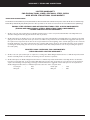
CUSTOMER LETTER
Dear Customer,
Congratulations! You are now the owner of an innovative Zodiac swimming pool that will allow you to make the most
of your summer.These instructions will help you easily and correctly install your Zodiac modular pool. Read them
carefully and make sure you understand them before you proceed. Before you begin, here is some additional
information that will help you through the installation process: Finding the right location for your pool is of the
utmost importance.To find the right spot, you must ask yourself a number of questions. How far is the property line?
Are there electrical lines overhead or underground? What about telephone lines, or gas and water pipes? You must
also consider the slope, soil composition and drainage on your property as well as the climate, prevailing winds and
available sunlight.
Minimum bearing capacity of ground under pool is to be 80k Pa.This may need an engineers soil test to verify.
Unstable soil may result in the pool moving and not remaining level.
Before commencing the installation of your pool, ensure that you have complied with council requirements and
obtained the necessary council permits.
Installation requires a minimum of 2 people and the amount of time varies according to the size and model of the
pool you have. However, it generally takes about 8 hours for an oval pool (not including the time required to prepare
the site and fill up the pool).
We also suggest installing your pool on a sunny and windless day. Installation of the liner on a warm day will make it
easier to fit.
Before starting to use your pool, it is important to know all about water treatment.We also recommend that you
check the fastenings (bolts and screws) every year to make sure that all of the parts are in good shape.
Ensure that the water level in your pool is maintained at the correct level for safe operation of the filtration system.
Never leave your pool empty.This can result in severe damage to your pool liner.
Never dive or jump into a modular pool and never walk or sit on the top deck as it is very dangerous and serious
injuries may occur. Failure to adhere to instructions concerning maintenance, safety, assembly, start-up and use could
pose serious health risks, especially to children.Your pool is designed to provide years of enjoyment, as long as it is
carefully and correctly installed and maintained. Read and make sure you understand the instructions before you start.
Work step by step, and take your time.
If you encounter any problems during installation or if you require additional information, please contact the Zodiac
retailer/dealer
or contact Zodiac Group Australia Pty Ltd
by phone 1800 229 526 or by fax 61 2 9757 2860
Happy swimming!
POOL WARRANTY REGISTRATION
Your pool is warranted by Zodiac Group Australia Pty. Ltd. It is advisable to register your pool within 30 days of purchase.
Complete and return your pool warranty registration card to Zodiac Group Australia. If you did not receive a warranty
registration card you can register your warranty online at http://www.zodiac.com.au or contact your pool dealer.
POOL CARE
Like a car your pool will remain looking its best if washed occasionally.As water is splashed out of your pool onto the decks,
verticals and wall, the water will evaporate leaving behind deposits of concentrated salts.This can be prevented by washing your
pool with soapy water then rinsing with fresh water to remove all the salts from the metal components of your pool, even
underneath the decks (rinsing with fresh water will help, but soap will give a better result).
2
SAFTEY FIRST
SAFETY FIRST!
NEVER UNDER ANY CIRCUMSTANCE stand, walk or sit on the top decks. Any fall could
result in spinal or neck injuries and/or possible drowning.Always enter the pool via the step entry system
or ladder provided with your pool. Do not jump or dive.
ALWAYS MAKE SURE THAT CHILDREN ARE SUPERVISED whilst in the pool area
and make sure that pool fencing and gates are adequate barriers to your children when the pool is not
being supervised.
ALWAYS FOLLOW THE INSTRUCTIONS contained in this manual. Incorrect installation can
lead to product failure and warranty voids. Please respect that your pool can be holding up to 60 tonnes
of water! Make sure that when joining the pool wall all bolts and nuts are used and tightened/ correctly.
ALWAYS KEEP ELECTRICAL HAZARDS AWAY FROM POOL AREA.
NEVER INSTALL YOUR POOL WALL IN WINDY CONDITIONS.
NEVER LIFT WALL CARTONS OR LARGE POOL CARTONS by yourself.These cartons
require two people to lift. Remember, lift with your knees bent and not with your back!
KEEP POOL CHEMICALS OUT OF REACH OF CHILDREN AT ALL TIMES.
3
INTRODUCTION
INTRODUCTION
Congratulations on the purchase of your new Zodiac pool.This pool is the product of more than thirty years continuous
development.The pool installation procedure has been set out in easy to follow step by step instructions with illustrations.
Please take the time to read your owners manual thoroughly before and during installation of your pool.Your warranty will be
void if the procedures in this manual are not followed. If you are having your pool installed by a professional installer it is your
responsibility to inspect the work at all stages to ensure that each step being undertaken complies with ALL instructions. Please
also read and follow the instructions relative to all accessories, i.e. pumps and filtration prior to installation.
IMPORTANT POINTS
LOCAL REGULATORY BODIES
When installing a new pool, you must comply with your local safety regulations and codes. As these regulations vary from
council to council it is a must that you check with your local council what the requirements for your site are, i.e. fencing
requirements. COMPLYING WITH LOCAL REGULATIONS AND CODES ARE YOUR RESPONSIBILITY.
CONTRACT INSTALLATIONS
Proper installation procedures are essential to ensure the best performance and durability of our pools in service. Zodiac are
not affiliated with any pool installers and we cannot accept any responsibility for problems caused by incorrect installation
procedures. It is strongly recommended that only reputable licenced and insured professional installers undertake the work
ensuring that it complies with the instructions contained in this manual. (not applicable in all states)
BEFORE YOU START
Before attempting pool installation, please make yourself familiar with the DVD and this manual. Make sure that the instructions
relate to the correct pool.Take the time to study the step by step procedures; an extra half an hour now could save
complications later on.
Allow plenty of time for installation, start early in the day.The installation process is made up of six defined stages.
1. Site selection
2. Site preparation
3. Frame installation
4.Wall installation
5. Liner installation
6. Skimmer box installation
Great care should be taken with all stages. If the site preparation and cross channel installation are not done with care and/or by
following the instructions contained in this manual the structural integrity of your pool may be reduced.
Take time, check and re-check.
Check lists can be found at the start of each frame installation section. Do not commence installation with parts missing.
Ensure that you have all the required tools on hand before commencing and make sure that you have help on hand at all times.
IMPORTANT
This pool has been designed and engineered (which complies with an approved engineer certificate). Installation of the
pool should be as shown in the assembly manual. Any deviation from this manual could cause serious injury and void warranty
of the pool.
4
TOOLS REQUIRED
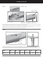
Clear plastic hose
CEMENT
Cut a piece of 9mm tubing around 20cm long,
fill the tubing with water. This can then be used
to find the level between one side and the other.
5
Water
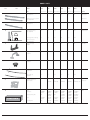
PARTS LIST
Ref.
Part
Model
2012
2412
2315
2715
3015
3815
Size
3.66 x 5.94 m
3.66 x 7.08 m
4.57 x 6.85 m
4.57 x 7.99 m
4.57 x 9.13 m
4.57 x 11.41 m
Carton
Radius/ curve long top deck 15’
PSL 725-001-R
-
-
10
10
10
10
Deck carton
Radius/ curve long top deck 12’
PSL 725-001-R12
8
8
-
-
-
-
Deck carton
A2
Straight side short top deck
PSL 725-001-0
4
6
4
6
8
12
Deck carton
B
Resin upright ends (1)
PSL 725-002-52
1-6
1-6
1-8
1-8
1-8
1-8
Vertical carton
Resin upright sides hollow (2)
2-6
2-8
2-6
2-8
2-10
2-14
A1
Open end exposed
PSL 725-002-52ov
C
Artium joiner plate
P20850
12
14
14
16
18
22
ACC Box
D
Long pin
P1000114
6
8
14
16
18
22
ACC Box
E
EZ-lock atrium
P1000116
13
15
15
17
19
23
ACC Box
Wall channel round end section
P13056UKIT
1-8
1-8
1-10
1-10
1-10
1-10
Rail Box
Side section (2)
P1294215
2-4
2-6
2-4
2-6
2-8
2-12
1
1
PWAL403
1
PWAL406
1
PWAL404
1
PWAL405
1
PWAL409 / 410
Wall carton
Liner
Brookstone
1
PH40BBST
-121952
1
PH40BBST
-122352
1
PH40BBST
-152252
1
PH40BBST
-152652
1
PH40BBST
-153052
1
PH40BBST
-153852
Liner
Brookstone Deep End
N/A
PH40BBST
-1223X52
N/A
PH40BBST
-1526X52
PH40BBST
-1530X52
PH40BBST
-1538X52
Opal
PH22TPSL
-121952
PH22TPSL
-122352
PH22TPSL
-152252
PH22TPSL
-152652
PH22TPSL
-153052
PH22TPSL
-153852
Opal Deep End
N/A
PH22TPSL
-1223X52
PH22TPSL
N/A
PH22TPSL
-1526X52
PH22TPSL
-1530X52
PH22TPSL
-1538X52
F
1
2
G
Wall with skimmer and
returns outlets
H
POOL LINER
6
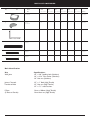
PARTS LIST CONTINUED
Ref.
Part
I
Model
2012
2412
2315
2715
3015
3815
Size
3.66 x 5.94 m
3.66 x 7.08 m
4.57 x 6.85 m
4.57 x 7.99 m
4.57 x 9.13 m
4.57 x 11.41 m
Carton
6
6
8
8
8
8
ACC Box
Base crown
PSL 725-007
J
Seal cap
PSL 725-006
12
14
14
16
18
22
ACC Box
K
P Post R
6
8
6
8
10
14
Separate
Joiner channel Female E
P160563
6
8
6
8
10
14
Channel
Joiner channel Male D
P160564
6
8
6
8
10
14
Channel
carton x1
3
4
5
7
Green
L
Orange
D1
Yellow
D1
Joiner channel Female C
P160562
Green
Bolt Identification
Use
Wall Joint
Specifications
1/4” x 3/8” Roofing bolt (Stainless)
1/4” x 9/16” Flat washer (Stainless)
1/4” Hex nut (Stainless)
Joiner Channels
Female to Male
1/2” x 1” Bolt (High Tensile)
1/2” Hex nut (High Tensile)
1/2” x 11/8” steel washers
P Post
(P Post to Female)
12mm x 100mm (High Tensile)
12mm Hex nut (High Tensile)
7
ENLARGED VIEW OF COMPONENTS
J
A2
D2
A1
E
B1
B2
F2
K
L
G
I
C
F1
8
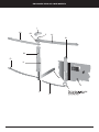
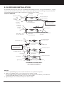
SITE SELECTION
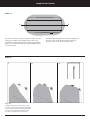
A. DETERMINE POOL LOCATION
Look over the various pool locations shown at right
1.TERRAIN
Look over your property for the most ideal pool
location. A large area is best. If you have no flat area
large enough for the pool then try to pick a spot
where you would have the least amount of digging to
do. Do not install in a major water drainage
depression or sewer drain field. Ground area around
the pool foundation should be level for 900mm out
from base of pool.
NO
NO
YES
NO
ALWAYS DIG AWAY TO
LEVEL THE SURFACE
2. CONVENIENT ELECTRICAL OUTLETS
DO NOT BUILD UP SURFACE
OR LOW SPOTS
Your pump and other accessories are operated by
electricity. If there are no outside electrical outlets,
you must have them installed by a qualified electrician.
3. OVERHEAD ELECTRICAL WIRES
The pool should never be placed directly under any
overhead powerlines for precautionary measures.
4. UNDERGROUND CABLES – CHECK
WITH LOCAL AUTHORITIES!
Before you start digging into the ground to level the
surface, it would be wise to check with your council
as to the location of any underground lines or pipes.
Dial 1100
5.TREES
Trees and their occupants are not the best of friends with swimming
pools. Falling leaves, branches and sap can be a constant problem in
keeping the pool water clean (along with bird droppings and insects
falling into the pool).These materials will necessitate cleaning your
filter unit more often.The further away from the tree, the better for
your pool.
B. CLEAR AREA
Clear the area of anything which may damage the pool. Remove any grass, weeds, stones, asphalt, tarred paper, poison, nut grass or
weeds (NOTE If weed killer is used wait 3 days after spraying before installing your pool, some poisons will adversely effect the
liner). Remove all dead plants as part of site preparation. All of these may puncture the pool liner.
Roughly level an area allowing at least 30cm extra distance around the pool as shown.If a sloping area is used, dig away dirt from
high side.The area to clear is shown on the pool layout plan.Take note of where the lowest point is and remove soil to this level.
Cleared Area
Pool Area
30cm
DO NOT FILL IN
THIS AREA
additional
cleared area
30cm
9
DIG EARTH AWAY
MAKE LEVEL
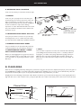
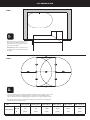
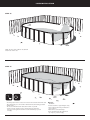
SITE PREPARATION
STEP 1.
When you choose the appropriate site for your
pool, make sure you allow for the distance
between the pool and property line as requires
by law in your municipality.
Important: Make sure the pool wall is at least
1 M from the fence so that the substructure can
be installed.
C
STEP 2.
B
A
B
A
C
B
B
C
Find a site where the ground is stable, level and well drained. Once you have selected your site, trace the
lines in accordance with the above diagram. Each line to be traced in is clearly identified by letter
A,B or C, which corresponds to a different length, according to the size of your pool.(Refer to chart)
Note: Line B is about 30.5 cm (12”) longer than the diameter of the assembled pool (see illustration)
This will allow you more leeway to work.
Model
Size
Dimensions
2012
3.66 x 5.94 m
2412
3.66 x 7.08 m
2315
4.57 x 6.85 m
A&B
2m
2m
2.5 m
2.5 m
2.5 m
2.5 m
C
2.6 m
3.9 m
2.9 m
3.9 m
5m
7.5 m
10
2715
4.57 x 7.99 m
3015
4.57 x 9.13 m
3815
4.57 x 11.41 m
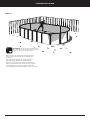
SITE PREPARATION
STEP 3.
Using the steel pegs at the centre of both
circles attach the end of the measuring tape
to the steel pegs.
STEP 4.
B
A
B
B
A
B
Using the tape measure and the can of spray
paint mark out the area to be cleared
and levelled for your pool.
Model
Size
2012
3.66 x 5.94 m
2412
3.66 x 7.08 m
2315
4.57 x 6.85 m
2715
4.57 x 7.99 m
3015
4.57 x 9.13 m
3815
4.57 x 11.41 m
A&B
2m
2m
2.5 m
2.5 m
2.5 m
2.5 m
C
2.6 m
3.9 m
2.9 m
3.9 m
5m
7.5 m
Dimensions
11
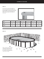
SITE PREPARATION
STEP 5.
Remove any grass sod and tree roots from the
area you have just outlined.
STEP 6.
Rake out pebbles, roots and other debris.
12
SITE PREPARATION
STEP 7.
Hint:
Attach the spirt level to the
straight edge using pvc adhesive tape.
Materials:
- Straight wood plank
Locate the lowest point and level the ground.
You should never fill in holes. Level out bumps instead
LEVEL POOL AREA
FIG 2
Unless you have access to a surveyor’s level,
the best, most accurate way to level
the ground is with a straight
Pool
plank (100mm x
50mm will do but it
should be straight)
and a spirit level (fig 2.).
Find the lowest spot within
the pool area and level the
ground to the lowest point. Dig away
the high areas – do not fill in the low
areas .
Machine excavated sites are rarely level. It is still
necessary to hand trim to ensure that the
framework will be level.The most critical areas
are the pool perimeter and cross channels.The
pool floor should be generally level but the sand
base can be used to fill any low spots. Note: If
not level, pool wall could buckle or crease.
BE SURE: recheck the level of the entire pool area. The success of installation depends upon how well this is performed.
Once the site has been cleared and levelled it is time to start assembling the base channels and P.Posts.
IMPORTANT NOTE:
Some noxious weeds, such as onion weed can grow up through the liner material damaging your pool liner.
To guard against this we reccomend that you treat the area with a suiteable weed killer(poison). Please insure the weed killer you
use is a recognised product and will not have any detremental effects on the vinyl material used in your pool liner.
13
FRAME INSTALLATION
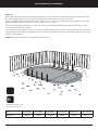
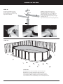
STEP 8. ASSEMBLY
Identify the P. posts, joiner channels (female E), joiner channels (male D) and joiner hardware (nuts,bolts & washers) required
for your size of pool.
Lay these components out on the ground in their correct order and assemble them as per the instructions in step 9. below
NOTE: Refer to page 17 for the layout of the size of the pool you have purchased.
D Male
D Male
E Female
E Female
Joiner channel female
Exploded view
Bolt
Joiner channel male
Nut
NOTE:
1. Diagram shows assembly for a 3706mm
wide section.
Washer
2. 4616 wide pools have 5 joiners in each
section (2 x E joiners , 2 x D joiners and
1 x C joiner
STEP 9. FRAME ASSEMBLY
Once the joiner channels have been assembled and bolted together the channel assembly is to be attached to the P.Posts.The same
components are used for both 3.6m wide pools and 4.5m wide pools, except a C Female joiner is added to the 4.5m pools.The
joining configurations are shown below.
3.8m wide
E Female
D Male
E Female
D Male
4.5m wide
E Female
D Male
E Female
14
D Male
C Female
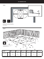
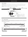
POSITIONING THE CHANNELS
STEP 10.
Once the channels have been assembled and all of the nuts and bolts have been tightened, It’s time to position the assembled
frames into the pool site. Place the first assembled channel across the width of the pool at a point 2100mm from the end of
the cleared area.
2100mm
NOTE:
2100 Refers to a 3.66m Pool, 2540 refers to a 4.57m pool.
STEP 11.
Place the 2nd and remaining channels at a point 1140mm from the adjacent channel.
NOTE: 1140mm measurements are taken from the centre of the channels
1140mm
1140mm
1140mm
NB. The instructions shown refer to a 7.08 x 3.66 pool refer to page 17. for the measurements for the other pools.
15
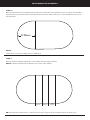
POSITIONING THE CHANNELS
STEP 12.
CHANNEL POSITIONING
Refer to page 21 for the end radius of each pool.
7.99 x 4.57 m
5.94 X 3.66 m - 19800 Lt
C
Y
A
X
B
B
9.13 x 4.57 m - 38000 Lt
7.08 X 3.66 m - 24200 Lt
C
Y
A
X
B
B
Outside measurement
Outside measurement
A= 3856 mm
B= 1140 mm Centres
C= 2100 mm
11.41m x 4.57m - 48500 Lt
6.85m x 4.57m - 27650 Lt
Y
Y
X
X= 4766 mm
B=1140 mm Centres
Y= 2540 mm
X
B
B
Note:The width measurements (A or X) can have a variance of + or - 5mm.
16
POSITIONING THE CHANNELS
STEP 13.
To check the alignment of the P. posts, position a string line along the back of the posts between two (2) steel pegs.
(Points A and B) if the posts are not correctly aligned they need to be tapped back or forward until the back of each post is
correctly aligned with the string line.
String line
A
B
Steel peg
Steel peg
STEP 14.
Once these steps have been completed you need to check the diagonal measurements of the pool frame.
A
B
C
D
Measure the two intersecting axis to ensure that the two straight sections are parallel.
The measurements of the points A to D and B to C must be equal.
17
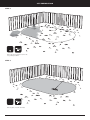
POSITIONING THE CHANNELS
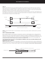
STEP 15.
When the end channels are in the correct position, spray paint a line on either side of each channel across the pool.This is to
mark out the areas to be excavated.When these areas have been marked out, the channels can be removed from the site.The
marked areas should be excavated to a depth of 100mm x 75mm wide across the pool from one side to the other with a 250 x
250 x 150mm excavation at each end for the positioning of the pre-cast concrete blocks.
An alternative to concrete blocks is to pack a strong sand/ cement/ screenings mix under the back of the channels (Rapid set pre
mix is ideal for this purpose). If you are using the cement mix rather than the concrete blocks, the excavations at the ends of the
channels will need to be dug out to 250 x 250 x 150mm.
Pool wall
Width 75 mm
Above view
250 mm
1140 mm
250 mm
DEPTH 100 mm
Side view
The depth of the
precast block 75 mm
Ground Level
75mm Concrete block
Position the concrete blocks into excavated area.
Depth of concrete
mix 150mm
NOTE- If using cement mix instead of concrete blocks, the cement mix is put in place after the channels have been positioned
and levelled.
STEP 16. INSTALLING FRAMES
Frames should be installed in such a way that no horizontal part of the P Post is situated higher than the existing ground level.
All P Posts must be level, as well as being level with all other adjacent P Posts.When checking the level of individual P Post it is
important to note that the vertical section of the P Post is not perfectly perpendicular to the horizontal, the level must be found
on the horizontal member of the P Post and not the vertical.The checking of adjacent P Post can be done by placing a level
(if longer than 1.1M) or sufficient straight edge across the top of the adjacent P Post .
THE LEVELLING OF THE P POST IS AN IMPORTANT EXERCISE THAT MUST BE DONE PRECISELY AND
REPEATEDLY UNTIL CORRECT.
NOTE- CONCRETE PADS:The use of concrete blocks or concrete mix at each end of the P Post is critical as it distributes the
load carried by the frames evenly into the soil below. Not using concrete pads will result in the frame sinking into the ground and
disturbing the level of your pool. Pads should be installed as shown below. DO NOT USE HOUSE BRICKS OR BESSER BLOCKS.
P Post
All excess areas to be filled with 8.1 wet sand/ cement mix
Joiner Channels
Existing ground level
Concrete pad
or concrete mix
18
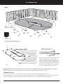
POSITIONING THE CHANNELS
STEP 17.
When all the channels have been positioned and levelled you need to recheck and ensure that the back of the P Posts are all in
line and the diagonal (refer to steps 13 and 14) measurements of the P Posts are all correct and equal.
Before proceeding check the measurements for the width of the pool between the inside of the P. posts should be as per table
below.The width measurements (A or X) can have a variance of + or - 5mm.
If all of the measurements and levels are correct you can now proceed with the backfill of the channels across the pool and
cement mix at the end of the channels.
The excavation for the channels cross the pool needs to be filled in with a wet mix of 8 to 1. sand and cement.This needs to be
packed in firmly around the channels right across the pool into the excavations at the end of each channel and up to the ground
level (top of the channels)
NOTE: Top of the horizontal P Posts and ground should be level.
Backfill all excavated area with
8 to1 sand and cement mix.
Model
Size
Distance A
2012
3.66 x 5.94 m
3.706 m
2412
3.66 x 7.08 m
3.706 m
2315
4.57 x 6.85 m
4.616 m
19
2715
4.57 x 7.99 m
4.616 m
3015
4.57 x 9.13 m
4.616 m
3815
4.57 x 11.41 m
4.616 m
Noosa Reef Deep End
Excavation & Channel Assembly
20
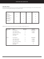
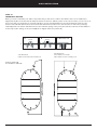
2. DEEP END EXCAVATION
All layout measurements and component assembly methods for both deep end and standard oval pools are shown in the Noosa
Reef Oval Instruction Manual.
The installation of a deep end pool involves a few more steps regarding site excavation. Site excavation plans and measurements
relevant to each model are shown below.
DIAL 1100 BEFORE YOU DIG
Make sure even after any Council approvals that there are no pipes or cables in the excavation area.
Although, shown here in very sharp, straight lines the finished preparation of compacted sand would desirably soften the changes of
angle as gradually and as smoothly as possible as to reduce the chance of wrinkling in the liner.
NOOSA REEF DEEP END EXCAVATION PLANS
1. SIDE VIEW
X
Pool Wall
Y
Pool Wall
X
Ground Level
Y
500
500
7080 x 3856
3010
6850 x 4766
2360
7990 x 4766
3500
2590
9130 x 4766
4640
2590
11410 x 4766
6920
2590
2170
2590
1000
21
700
200
200
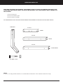
DEEP END EXCAVATION
A
Pool Wall
B
Pool Wall
2. END VIEW
POOL FLOOR
A
B
500
500
POOL FLOOR EXCAVATION
2456
7080 x 3856
6850 x 4766
200
500
3366
7990 x 4766
3366
9130 x 4766
3366
11410 x 4766
3366
22
500
200
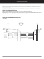
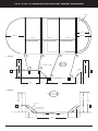
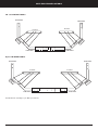
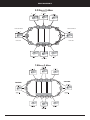
7.08 X 3.66 M X 1.32 NOOSA REEF DEEP END POOL CHANNEL POSITIONING
200 mm
1630 mm
1830 mm
1830mm
1140 mm
1140 mm
BETWEEN CENTRES
BETWEEN CENTRES
1
1. SIDE VIEW
1140 mm
BETWEEN CENTRES
2
X
1320
4
3
Y
1320
1140 mm CENTER TO CENTER
1820
1
2
1820
1830
1830
X
Y
STANDARD FRAME
500
500
3
4
DEEP END FRAMES
200
3010
1000
2170
700
2. END VIEW
A
B
1320
1320
1820
1820
POOL FLOOR
A
B
EXCAVATION 200 mm
INTO POOL FLOOR
500
500
POOL FRAME
POOL FLOOR EXCAVATION
200
500
2306
23
500
200
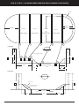
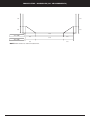
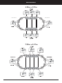
7.99M X 4.57M X 1.32 M NOOSA REEF DEEP END POOL CHANNEL POSITIONING
200 mm
2085 mm
2285 mm
1140 mm
2285 mm
1140 mm
BETWEEN CENTRES
1140 mm
BETWEEN CENTRES
1
1140 mm
BETWEEN CENTRES
2
BETWEEN CENTRES
5
4
3
1. SIDE VIEW
X
Y
1320
1320
1140 mm CENTER TO CENTER
1820
1820
1
2
3
X
Y
500
500
STANDARD FRAME
5
4
DEEP END FRAMES
4640
2590
700
1000
200
2. END VIEW
A
B
1320
1320
1820
1820
POOL FLOOR
A
B
EXCAVATION 200 mm
INTO POOL FLOOR
500
500
POOL FRAME
POOL FLOOR EXCAVATION
200
500
3216
24
500
200
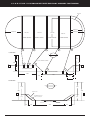
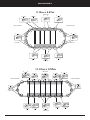
9.13 M X 4.57 M X 1.32 M NOOSA REEF DEEP END POOL CHANNEL POSITIONING
200 mm
2085 mm
2285 mm
1140 mm
2285 mm
1140 mm
BETWEEN CENTRES
1140 mm
BETWEEN CENTRES
1
1140 mm
BETWEEN CENTRES
2
BETWEEN CENTRES
5
4
3
1. SIDE VIEW
X
Y
1320
1320
1140 mm CENTER TO CENTER
1820
1820
1
2
3
X
Y
500
STANDARD FRAME
4
500
5
DEEP END FRAMES
4640
2590
1000
700
200
2. END VIEW
A
B
1320
1320
1820
1820
POOL FLOOR
A
B
EXCAVATION 200 mm
INTO POOL FLOOR
500
500
POOL FRAME
POOL FLOOR EXCAVATION
200
500
3216
25
500
200
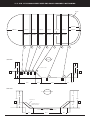
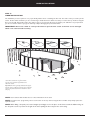
11.41 M X 4.57 M NOOSA REEF DEEP END POOL CHANNEL POSITIONING
200 mm
2085 mm
2285 mm
1140 mm
1140 mm
1140 mm
1140 mm
1140 mm
1140 mm
CENTRES
CENTRES
CENTRES
CENTRES
CENTRES
CENTRES
1
2
4
3
5
X
1. SIDE VIEW
2285 mm
6
7
Y
1320
1320
1820
1140 mm CENTER TO CENTER
1820
2
1
3
4
5
X
Y
STANDARD FRAME
500
500
7
6
DEEP END FRAMES
6920
2590
1000
700
200
2. END VIEW
A
B
1320
1320
1820
1820
POOL FLOOR
A
B
EXCAVATION 200 mm
INTO POOL FLOOR
500
500
POOL FRAME
POOL FLOOR EXCAVATION
200
500
3216
26
500
200
DEEP END PART QUANTITIES
DEEP END POOLS
Note: All parts required for the size of pool you have purchased will be as per the parts list pages 6 & 7 of the instruction manual,
except for the following which will change to the quantities as listed.
Parts
7.08 x 3.6
7.99 x 4.5
9.13 x 4.5
11.41 x 4.5
P. Post
(P.Post R)
4
4
6
10
Joiner Female E
(P160563)
4
4
6
10
2
3
5
4
6
10
Joiner Female C
(P160562)
Joiner Male D
(P160564)
4
Additional parts to pages 6 & 7 required for deep end installation supplied with your pool.
Pool width
Name
3.6m
4.57m
Quantity
Part No.
Deep End Post
8
PPOSTRDE
Joiner Channel short
4
P160567
Joiner Channel extra long
2
P160566
M12 Bolt and Nut
16
P-Post RDE
4
Deep End Post
4
PPOSTRDE
Joiner Channel short
4
P160567
Joiner Channel long
2
P160565
Joiner Channel extra long
2
P160566
M12 Bolt and Nut
16
P-Post RDE
4
27
DEEP END PARTS LIST
DEEP END INSTRUCTION MANUAL SUPPLEMENT MUST BE USED IN CONJUNCTION WITH THE
STANDARD NOOSA REEF OVAL INSTRUCTION MANUAL.THIS SUPPLEMENT ONLY COVERS THE
FOLLOWING:
1. Deep end parts list
2. Deep end excavation plans
3. Deep end frame assembly
ALL OTHER ASPECTS OF THE INSTALLATION PROCESS ARE COVERED IN THE OVAL INSTRUCTION MANUAL.
PPOSTRDE
P160567
SHORT
P160565
LONG
P160566
EXTRA LONG
M12 BOLT & NUT
NOTE:
In order to correctly assemble channels, it is essential that the instructions in the manual are followed correctly
28
DEEP END FRAME ASSEMBLY
A0 3.66 M WIDE POOLS
P.POSTRDE
P.POSTRDE
P160567
P160567
BL
CK
O
O
CK
BL
P.POSTRDE
P.POSTRDE
P160566
B) 4.54 M WIDE POOLS
P.POSTRDE
P.POSTRDE
P160567
BL
P160567
O
CK
CK
O
BL
P.POSTRDE
P160566
P160565
Standard frame assembly as per Oval pool manual
29
P.POSTRDE
FRAME DETAIL - ASSEMBLED (ALL MEASUREMENTS)
900
900
500
500
200
200
2306
3660 WIDE
500
500
3216
4570 WIDE
500
500
NOTE: Inside channel to channel measurement.
30
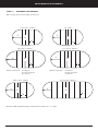
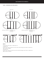
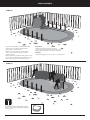
POSITIONING THE CHANNELS
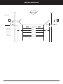
STEP 18. MARKING OUT END RADIUS
5.94 x 3.66 m
7.99 x 4.57 m
A
A
C
C
B
B
7.08 x 3.66 m
A
9.13 x 4.57 m
A
C
C
B
B
Inside post measurement:
A= 3706 mm
B= 1140 mm centres
C= 1830 mm
Inside post measurement:
A= 4616mm
B= 1140 mm centres
C= 2285 mm
11.41 x 4.57m
6.85 x 4.57
C
C
B
B
NOTE:
You will require two people to complete step 18.
3.66 Wide pools
Find the centre of A (point C) from the centre of the channel using a tape measure to mark the arc
1830 mm with screwdriver.
4.57 Wide pools
Find the centre of A (point C) from the centre of the channel using a tape measure to mark the arc
2285 mm with a screwdriver.
31
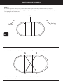
ASSEMBLY
STEP 19.
NOTE: Only the end radius wall channels are adjustable and have indexing pins.The intermediate wall channels side sections
are not adjustable and are used as the straight sides
B
A
STEP 20.
INDEX:
You must now assemble the wall channels.This is a three step process.
Hole (12) = 3.6mt Pools (w)
STEP 1: Detach the indexing pins attached to the wall channel.
Hole (15) = 4.5mt Pools (w)
STEP 2: Identify on the reverse side of the wall channel (while loooking underneath the wall channel) the approximate radius of your pool
and insert the indexing pin into the corresponding hole - refer to illustration “A” above.
STEP 3: Turn the wall channel right side up and align once again the pin with the corresponding hole. Press down the wall channel onto the
pin to complete the assembly - refer to illustration “B” above. Repeat these steps for each wall channel and indexing system.
A
B
13 mm
-13
Important: The wall channels of the straight sections
are shorter (1067 mm). Install the wall channels
by placing them on the inside of the braceless
the joiner plates will hold
frames. In this way, the feet of
the vertical sleeve on either side (ill. C).
Continue by inserting the end of each wall channel into
joiner plates. Ensuring that they are firmly inser ted and
leaving a space of 13 mm (ill. A) between each wall channel
of the round sections. Insert and leave a 50 mm
space on the straight side (ill.B).
Note: The wall channels should be positioned on the mark of the radius
32
50 mm
50
C
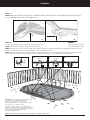
ASSEMBLY
STEP 21.
Now that the wall channels have been positioned, it is necessary to peg the channels into place with steel pegs, to ensure that
the radius does not move out of place during installation of the wall and filling of the pool.
x
x
x
x
x
x
x
x
x
4 steel pegs (x)
x x
x
6 steel pegs (x)
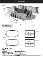
STEP 22.
Model
Size
Approx sand required
2012
3.66 x 5.94 m
2412
3.66 x 7.08 m
2315
4.57 x 6.85 m
2715
4.57 x 7.99 m
3015
4.57 x 9.13 m
3815
4.57 x 11.41 m
1.8 cubic m
2.0 cubic m
2.2 cubic m
2.5 cubic m
2.7 cubic m
2.9 cubic m
PLACE SAND
Place the required amount of builders Fatty sand in the centre of the excavated area.The table above gives the required amount of
sand. Do not spread the sand at this stage. Ensure that there is no sand within approx 900mm from pool edge as it will be in the
way of wall installation later on.
NOTE: Builders Fatty sand is the only sand recommended as a base for the pool. Any other sand may damage the liner.
33
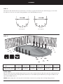
ASSEMBLY
STEP 23.
SIDE POST
Slip the resin uprights (with the holes in
the bottom) over all the straight section posts.
The vertical sleeve is properly positioned when the
joiner plate is inserted into the notch at the
lower end of the sleeve.
Model
Size
B2 Upright
2012
3.66 x 5.94 m
2412
3.66 x 7.08 m
2315
4.57 x 6.85 m
2715
4.57 x 7.99 m
3015
4.57 x 9.13 m
6
8
6
8
10
3815
4.57 x 11.41 m
14
END POST
Important: The resin uprights used in the round sections
(i.e. B1) are different than those used in the straight sections
(i.e. B2) of the pool. Please note that no base crowns are to
be installed on upights B2 in the straight sections of the pool.
Before you commence to install the radius vertical
you will need to determine where your skimmer is
to be positioned. Refer step 24.
Put your first resin upright in place on this joiner plate
and begin installing the wall. The upright is properly
positioned when the joiner plate is inserted into the
notch at the lower end of the straight. To make it easier
to attach the upright to the joiner plate, slant the straight
slightly towards the interior of the pool while inserting it.
This upright will serve as your starting point as you install
the wall.
Temporarily put the top decks to hold the end
verticals in place while installing the walls.
Model
Size
B1 Upright
2012
3.66 x 5.94 m
2412
3.66 x 7.08 m
2315
4.57 x 6.85 m
2715
4.57 x 7.99 m
3015
4.57 x 9.13 m
6
6
8
8
8
34
3815
4.57 x 11.41 m
8
WALL INSTALLATION
STEP 24.
IMPORTANT NOTICE
Before you start to install the pool wall it is important that you take notice of where the skimmer box is to be installed (see
diagram below). Due to the fact that the wall joint must be located in a defined position on the oval end of the pool, it is at one of
these points that you should start to unroll the wall.There are two nuts/bolts/washers located approximately 10mm from the
bottom of the wall that will not fit into the bottom wall channel.These bolts need to be located in one end of the position(s)
marked (B) where the bottom wall channels are at the maximum spacing in the joiner plate and hence behind a vertical. Failure to
do this may result in damage to the pool wall.(Refer to diagram below for positions B)
A
13 mm
B
50 mm
C Overhead view
4.5m Wide Pools
7.99 x 4.57m, 9.13 x 4.57m
6.85 x 4.57m and 11.41 x 4.57m pools.
3.6m Wide Pools
5.94m x 3.66m and 7.08 x 3.66m Pools
Positions marked B.
are suitable for wall bolts
35
WALL ASSEMBLY
STEP 25.
You now have to install the pool wall. A minimum of two
or three people are required to install the wall and
there should be no wind at the time.
Further more, we suggest that you use the packaging
or 60 cm x 60 cm (2’ x 2’) wooden board to help
manoeuvre the wall.
Important:
The skimmer and water return holes are located
at the top of the unrolled start of the wall, and it is essential
that they should be located in a round section of the pool.
Materials:
- Cardboard packaging or a 60 cm x 60 cm (2’ x 2’) wooden board.
Insert the wall into the wall channel, starting from the centre
of one of the joiner plates. Make sure the skimmer hole is at
the place where you want to put the filtration system.
STEP 26.
As you unroll the wall, you must install the uprights.
However do not forget to install the base crowns only
on the end posts.
36
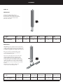
WALL ASSEMBLY
STEP 27.
Wall Short
Control Notch
Wall Long
Control Notch
37
WALL ASSEMBLY
STEP 28.
When both ends of the wall are aligned, use two
or three phillips head screwdrivers, starting at the
bottom of the wall, to keep the wall aligned until
you have installed the bolts.
Screwdriver
Option 1
Option 2
STEP 29.
Assemble the 3/8” x 1/4” bolts, 1/4” nuts and 1/4” washers into the bolt hole provided and firmly tighten. It
is important to have the washers and nuts on the outside of the pool with the bolt head on the inside. Once
this has been done, remove any screwdriver burrs from the wall screws with a file. Cover the bolt
heads from top to bottom with duct tape.
Remove the resin upright located at the wall joint
using a screwdriver. To fasten the wall joint, it is
very important to use the washers provided.
Tighten the bolt heads on the inside of the pool
and the nuts and washers on the outside.
Ensure that all bolts and hole are used
(except as mention in step 24). Use the
bolts provided with the wall.
Once the wall joint has completely bolted,
replace the last resin upright and top deck,
without forgeting the base crown.
38
WALL ASSEMBLY
STEP 30.
Cover the wall joint with two or three layers
of duct tape. Make sure to cover the bolt heads
so there is no sharp edges that can damage the liner.
File any bumps or sharp edges to prevent damaging
the liner.
39
WALL ASSEMBLY
STEP 31.
SPREADING AND LEVELLING THE SAND
Using a tape measure and permanent marking pen mark a line around the inside perimeter of the pool 150mm up from the
bottom edge of the wall.
b. Use the wooden screed (2m) to level the sand before rolling approx 75mm deep (50mm after rolling)
c. Build an even coving of sand around the wall of the pool approximately 200mm high + compact tightly
(150mm after compacting) up to the line around the inside perimeter of the pool.
NOTE: The coving is critical to stop the liner from going under the wall when filled with water.This will be the finished
compact level of the sand coving.
IMPORTANT SAND SHOULD BE DAMP BUT NOT WET TO COMPACT THE SAND CORRECTLY.
A
C
B
Pool Wall Coving
150 mm
50 mm
200 mm
40
ASSEMBLY
STEP 32.
RIGHT
WRONG
A
A
3.65m x 7.08m;
4.57m x 6.85m;
3.65m x5.94m;
4.57m x11.41m
4.57m x 7.99m;
4.57m x 9.13m;
Before you begin installing the liner, you have to insert the pins into the appropriate anchoring slots of the
top deck index system. Please see illustrations for the correct pin location for the size of the pool you are
assembling on the next pages to determine which anchoring slots match the dimensions of your pool.
Important: Make sure that you insert the pin in the right direction as illustrated above.
RIGHT
WRONG
To position the pin in the appropriate anchoring slots, refer to the next three pages (Pages 32, 33, 34).
41
DECK ASSEMBLY
5.94m x 3.66m
B
B
LONG PINS
A
A
C
C
LONG TOP DECK
A
LONG TOP DECK
A
A
LONG PIN
A
LONG PIN
C
C
A
A
LONG PINS
7.08m x 3.66m
42
B
B
DECK ASSEMBLY
6.85m x 4.57m
LONG TOP DECK
LONG TOP DECK
7.99m x 4.57m
43
DECK ASSEMBLY
9.13m x 4.57m
C
A
C
LONG PINS
A
A
A
B
B
LONG TOP DECK
B
LONG TOP DECK
B
B
LONG PIN
B
LONG PIN
B
B
A
C
A
C
LONG PINS
11.41m x 4.57m
C
LONG PINS
C
A
A
A
A
A
B
A
B
LONG TOP DECK
LONG TOP DECK
B
B
B
B
LONG PIN
LONG PIN
A
B
B
A
A
A
A
LONG PINS
44
A
C
C
LINER INSTALLATION
STEP 33.
LINER INSTALLATION
The installation process requires 2 or 3 people. Firstly lift the carton containing the liner into the centre of the pool and open the
carton. At the radius end where you are commencing to install the liner it will be necessary to remove the top decks to hang the
liner over the wall.Temporarily replace the decks as you proceed to hang the liner around the pool wall.This is very important if
you do not refit the decks as you go the wall may collapse damaging the pool wall and liner.
IMPORTANT: Do not use a knife or a sharp instrument to open the liner carton as the liner can be damaged
which is not covered under warranty.
.
Use the liners vertical seam as a guide and make
sure the seam is vertical and perpendicular to the
wall and the bottom.
Important: The liner is generally smaller than the support
structure of the pool. Because it stretches more easliy when
warm, it is important that the liner be installed on a warm
sunny day.
NOTE: Use footwear with soft flat soles to reduce indentations in the sand.
NOTE: You will need to progressively remove each section of the top deck to hang the liner and then temporarily replace the
topdeck section.
NOTE. When filling a deepend pool, several weights (sand bags) need to be place on the liner around the 200mm ledge of
the deepend section to prevent the weight of the water pulling the liner away for the sand coving.
45
LINER INSTALLATION
STEP 34.
B
A
Avoid leaning heavily against the wall when getting into
the pool as this could damage it. Remove the liner
from the centre of the pool toward the sides.
Use the liner’s bottom seam(s) as guide and make sure the
seam(s) are parallel to the straight sections and to the
imaginary line which links points A and B in the illustration
above. It is recommended that you begin installing the liner
in a round section.
STEP 35.
1
2
3
Hung liner:
To install the liner, use its vertical seam as a guide
and make sure the seam is vertical and perpendicular
to the bottom seam between wall and bottom. Make
sure the bottom seam between wall and bottom
sits on the cove. Hang the liner onto the wall.
46
LINER INSTALLATION
STEP 36.
Make sure the seam between the wall and
bottom sits on the cove.
STEP 37.
An ordinary vacuum cleaner can be used to remove the air between the liner and the wall.
This technique helps you to remove folds in the liner. However, the following precautions
should be taken:
- Do not use an industrial vacuum cleaner, which could be to powerful.
- Tape the end of the vacuum hose before inserting it into the return water
hole as not to damage the liner. Seal the hose to the wall with tape to prevent
air leakage.
47
Materials:
– Cardboard
- Insert the vacuum hose approximately 20 cm (7î)
into the wall, and ensure that you will be able to
remove it later on.
- Attach the hose to the wall with tape.
- Cover the skimmer hole with cardboard and
tape in place to prevent air leakage.
LINER INSTALLATION
STEP 38.
IMPORTANT: Do not use bare feet. Remove your
shoes and walk in stocking feet as sharp toe nails can
damage or cut the liner when pushing it in.
Before turning on the vaccum cleaner make sure the bottom
seams are even on the coving and the perpendicular seams
are vertical.
Turn on the vacuum cleaner. As the vacuum pulls the liner
tight against the wall. Push the liner outward with your
feet to iron out any folds in the floor. The liner should now be
drawing correctly back into the pool wall. At this point you can
start running water into the pool, you will need to keep the
vaccum running until you have at least 150mm of water in your pool.
48
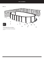
ASSEMBLY OF TOP DECK
STEP 39.
It is now the time to permanently reinstall the top
decks. it is important that you start installing the top
deck ofthe straight side section first before proceeding
with the installation of the long top deck (round section).
Install the first top deck on the wall making sure the
upright is leveled and situated in the middle of the
top deck hole.
Model
Size
2012
3.66 x 5.94 m
2412
3.66 x 7.08 m
2315
4.57 x 6.85 m
2715
4.57 x 7.99 m
3015
4.57 x 9.13 m
3815
4.57 x 11.41 m
Long
8
8
10
10
10
10
Short
4
6
4
6
8
12
STEP 40.
Going in a clockwise direction, install the
next top deck overlapping the first one
while making sure the pin is inserted in
the appropriate anchoring slots. Repeat
the operations for both straight sections
of the pool.(see next page)
49
ASSEMBLY OF TOP DECK
STEP 41.
— alignment
notch
A A
Arrow see below
2
1
C
B
A
A
B
C
Outside of wall
A = 12’ = 3.66m
3.66m x 7.08m;
4.57m x 9.13m;
3.66m x 5.94m;
4.57m x 6.85m;
4.57m 7.99m;
4.57m x 11.41m
Going in a clockwise direction, install a long top deck (round section) on a short top deck.To make it easier to locate the interior alignment slots while you are installing
the top deck, alignment notches have been added close to each pin (male part of the top deck) (illustration 1).
These notches will help you locate the central alignment slot corresponding to each pool size. Simply move the arrow on the interior of the top deck cap (illustration
2) towards the appropriate notch (A). Repeat these operations to complete the top deck installation of the round section of the pool.
NOTE: Standing on the outside of the pool, line up the left hand notch with the arrow on the top deck.
STEP 42.
A
B
16 mm
To make the pieces fit together, you may have to use the adjustment points provided for this purpose and move the top deck to the left or right. In this case the
top deck should be moved approximately 16mm to the left or the right (illustration A) to ensure that upright is levelled and situated in the middle of the top deck
hole. See step 39. Screw the top deck in place with the EZ-lock system (illustration B). Repeat these operations to complete the top deck installation.
Model
Size
2012
3.66 x 5.94 m
2412
3.66 x 7.08 m
E-Z Lock
13
15
2315
4.57 x 6.85 m
17
50
2715
4.57 x 7.99 m
19
3015
4.57 x 9.13 m
15
3815
4.57 x 11.41 m
23
ASSEMBLY OF TOP DECK
J
STEP 43.
D2
You must now install the deck caps.
The deck cap clips onto the EZ-Lock.
Apply a downward pressure on the cap
clips around the EZ-Lock.
E
A2
Installation is performed in 2 steps as per
Demonstration align from the inside to the
outside. B) Clip the deck cap to the EZ lock by
grabbing and pulling it toward the outside of
the pool while simultaniously pushing the upright
toward the inside (c).
Important: Excessive pressure may damage this part.
B2
STEP 44.
IMPOR TANT:
Carefully remove the hose of the vacuum cleaner from the pool.
Begin filling your pool with water.Before making any openings
in the liner to fit the skimmer fill the pool with 60 cm (24”) of water
to stretch the liner fully to the skimmer box cut out. At this point you
may fit the skimmer box and eyeball fitting as per the following instructions.
51
SKIMMER BOX INSTALLATION
ONE PIECE RETURN FITTING
One piece return fitting installation this step
is not to be commenced until there is at
least 60cm of water in the pool.
Before attaching the return fitting to the
pool, it is necessary to cover the threads of
the return fittings with a thin layer of Teflon
tape to ensure a watertight seal.
1/ Using a small piece of cardboard push the
liner back against the metal pool wall to
locate the exact position of the circular cutout in the wall, and using a sharp knife
carefully cut a circular hole in the liner (from
the outside) approximately 3mm smaller
than the cut-out in the metal wall.
2/ Fit a cork gasket over the barrel of the
fitting and a rubber gasket between the pool
liner and the metal pool wall, and push the
fitting through the wall from the inside of
the pool.
3/ The remaining rubber gasket and the cork
gasket are now fitted over the barrel fitting
from the outside of the wall, with the rubber
gasket up against the pool wall, the lock nut
is now screwed onto the barrel and
tightened firmly to ensure a watertight seal,
care must be taken to ensure that the
locknut is not over tightened causing the
flange on the barrel to rotate and distort the
liner, if this occurs the lock nut should be
loosened, the gaskets repositioned and the
lock nut re tightened.
4/ The adjustable directional eyeball fitting,
can now be screwed into the face of the wall
return fitting.The outlet in this fitting (the
return to the pool) should face away from
the opening (the inlet) to the weir skimmer
assembly.
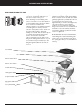
Cover P5315
Vacuum plate P5314
Skimmer basket P5316
Skimmer door P5317
Pool wall & liner
Double gasket P5318
Face plate P7506
Single gasket P7518C
Universal quick snap
(2) P5346
Cover plate P73502
Screws P7514
Eyeball return
P75042
52
Complete Skimmer
P5802
SKIMMER BOX INSTALLATION
SILICONE SEALANT REQUIRED (NOT SUPPLIED)
Important notice: Do not use the silicone sealants that are designed for use with windows and glass as they have an acidic cure
and can damage vinyl and some plastics. If the sealant smells like vinegar do not use it for this application.
A. Insert the double layer gasket around the cut out in the pool walll that there is a gasket layer on each side of the pool wall and
the screw holes line up (DO NOT UNDER ANY CIRCUMSTANCES CUT THE GASKET.)
B. Silicone sealer should now be applied to the back of the face plate, the front of the weir skimmer box, and to both sides of the
single rubber gasket in a single bead of approximately 5mm to assist in forming a leak proof seal between the liner and the
pool wall.
C. Use the screws supplied to locate the 4 corner screw holes of the skimmer box. Please make sure that the pool water depth is
at least 60cm before fitting the skimmer box as the liners can be under very high tension in the initial stages of filling the pool and
skimmer installation at this time can damage the liner.The four (4) corner screws are fitted from inside the pool, through the face
plate, single gasket double gasket and the pool wall, through into the skimmer box. Initially tighten screws 3 to four turns only.
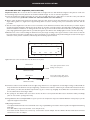
D.With the four corner screws holding the skimmer box in place begin screwing in the upper and lower centre screws so that the
face plate starts to bend into a similar shape to the pool wall (do not over tighten screw.)continue fixing the screws from the upper
and lower centre position outward, as indicated by the numbering sequence below.
1st
1st
6th
3rd
2nd
4th
5th
8th
7th
7th
8th
5th
2nd
4th
1st
3rd
6th
1st
Tighten the four corner screws first once all others are in place.
Skimmer Box
Pool Wall
1. Face plate position with 4 corner
locating screws in place
Skimmer Face Plate
Skimmer Box
2. Face plate position with centre
screw almost completely fastened
Pool Wall
Skimmer Face Plate
E. Continue to fasten screws until all screws are tight, being careful not to over tighten the screws. Higher voltage cordless drills can
strip the thread in the skimmer box. Upon tightening a small amount of silicone sealant may be extruded from between the face
plate and the pool liner, this should be wiped with a rag as to remove any unsightly excess. Allow the recommended cure time
for the sealant before immersing in water.
F. The opening for the skimmer box can now be cut into the liner. It is important that this area be checked for leaks periodically.
(You can now cut the opening in the liner.)
G. Congratulations.The assembly/installation of your pool is now complete.You may now install the filtration motor/pump as per the
equipment suppliers instructions.
H. Operating instructions
1.To adjust inlet flow direction loosen knurled outer ring of eyeball fitting, move ball to desired position and tighten knurled ring
hand tight..
2.To clean basket, only remove skimmer cover and pull it out.
3. To attach vacuum cleaner hose, remove top cover. Put the vacuum adapter into the skimmer fill hose with water and insert
vacuum hose to the vac adapter.
53
Backfill Requirements for
Noosa Reef Inground
Installation
54
E. IN GROUND INSTALLATION
It is imperative when any part of the pool is installed below (finished) ground line, for inground installation or a sloping
site the pool wall must be maintained in a stable condition by carefully placed sub-soil drainage and prepared back-fill.
The maximum inground for the walls is 1220 mm, for pools up to 12m in length.
Slop away
from pool
POOL IN GROUND
Open spoon
drain around pool
Pool coping
Pool wall
8:1 Coarse sand:cement
Slope of ground
Earth
Concrete path
or walk way
450mm Wide
8:1 coarse
sand:cement
Underground drainage
system to remove water
around base of pool
50mm Gravel
around drainage pipe
Concrete path
or walk way
Slop away
from pool
Pool wall
Slope of ground
Earth
bank
Earth
450mm Wide
8:1 coarse sand:cement
50mm Gravel
around drainage pipe
E.G.L
450 mm Wide 8:1
coarse sand:
8:1 Sand & cement mix
around base of wall
Pool
Excavated bank as per
50 mm Gravel
Agricultural pipe
Underground drainage
system to remove water
around base of pool
New levelled ground
450 mm
8:1 Sand & cement mixl
Pool
8:1 Sand & cement mixl
50 mm Gravel
E.G.L
E.G.L
Agricultural pipe
Pool
8:1 Sand & cement mixl
50 mm Gravel
Agricultural pipe
Approved retaining wall
APPROVED RETAINING WALL
BY LOCAL AUTHORITY
NOTES:
1. Prior to any backfilling, the pool is to be full of water for one day, check for any leaks.
2. Walls to be backfilled with 8:1 coarse sand/cement mix (machine mixed).
Use only sufficient water to hold mix together. Do not over moisten the mix. Ensure pool is full before
commencing backfill. Maintain pool full for one month after backfill.
3. Agricultural pipe to be continuous and sloped to the free outlet.
55
POOLCARE QUESTIONS AND ANSWERS
POOL CARE
1. CONTROL OF “pH”
The pH is the measure of acidity or alkalinity of the pool water. If the pH is incorrect, anti-bacterial treatment will not be
completely effective.The ideal pH for swimming pools is between 7.4 and 7.6.These should be checked daily with the Pool Water
Test Kit.
The following table describes how to control the pH.
Circulate the water for three hours and test the pH again, and if necessary, add further chemicals.
pH
0 to 7.2
7.4 to 7.6
7.8 to 14
EXPLANATION
Pool water is too acidic.
Eyes and skin may be IRRITATED.
Metal and plastic parts may be damaged.
TREATMENT
Add pH RAISE (Sodium Bi-Carbonate).
Add no more than 25 grams per 4540 L
(25 grams = 2 level tablespoons approx.)
IDEAL
Pool water is too alkaline.
Water may become cloudy.
Liner may be damaged.
Add pH REDUCER (Sodium Bi-Sulphate).
Add no more than 25 grams per 4540 L
(25 grams = 2 level tablespoons approx.)
2. ANTI-BACTERIAL TREATMENT
One method of keeping the swimming pool free of harmful bacteria is by adding Chlorine to the water using Daily Dose Chlorine
(Calcium Hypochlorite) in powder or tablet form. However, Ultra Violet light from the sun quickly reduces the Chlorine Residual the amount of Chlorine available to fight bacteria. By adding Stabiliser (Cyanuric Acid) the Chlorine loss can be reduced.The
Cyanuric Acid level should be maintained at 50 parts per million. Cyanuric Acid Test Kits are available from your Dealer.The ideal
Chlorine Residual is between 1.0 and 1.5 parts per million (p.p.m.) for unstabilised pools and 0.6 to 1.0 p.p.m. for stabilised pools.
This should be checked daily with the Test Kit.
If using Nature2 chlorine usage should be reduced by 70%.
3. STEP-BY-STEP TREATMENT
Initial or New Season Treatment
1.
Adjust pH to between 7.4 and 7.6.
2.
In the evening, add Chlorine at a rate of 10 grams per 1000 litres.
If the pool is to be stabilised: approximately 12 hours after adding Chlorine, add Stabiliser (Cyanuric Acid).
3.
Run filter all night.
4.
Chlorine Level: For healthy sparkling water the chlorine level should be between 0.6 and 1.0 p.p.m. in “stabilised” pools and
between 1.0 and 1.5 p.p.m. for “unstabilised” pools.The use of Stabiliser will maintain the chlorine level for a longer time as it
acts as a sunlight screening agent and thus minimises the loss of Chlorine caused by sunlight.
Remember the usage rates vary according to climatic conditions and the number of people using the pool.
5.
Testing:Testing of pool water should be carried out in the morning and additions of Chlorine made in the early evening. pH
RAISE and pH Reducer can be added when required but always be certain to spread the chemicals over the whole pool.
Daily Treatment - Unstabilised Pools
As a guide, 10 grams per 1000 litres should be sufficient to maintain a chlorine residual of 0.6 to 1.0 p.p.m. in the pool water, but
naturally the dose will vary according to climatic conditions and how much the pool is used. Note: Do not place liquid chlorine
manually. Refer to Important Information on page 1.
Daily Treatment - Stabilised Pools
When the pool water has been stabilised, the use of 2.5 grams per 1000 litres of Chlorine should be sufficient to maintain a
chlorine residual of 1.0 to 1.5 p.p.m. Check the level with your Test Kit and vary the dose if necessary. Stabilised pools have to be
super-chlorinated once every two weeks and this is done by adding Chlorine at the rate of 5 grams per 1000 litres of water. Note:
Do not use liquid chlorine.
56
POOLCARE QUESTIONS AND ANSWERS
Shock Treatment
Should algae or objectional odours occur, add 14 grams of Chlorine per 1000 litres in the evening when the pool is not in use and
run filter for 2 hours to disperse the chemicals.
Chemical Quantities
To Add Chemicals: Dissolve the chemicals in a half-filled bucket of water and pour into the pool in the stream of returning filter
water or while walking around the pool.When chlorine is dissolved in water a Calcium Residue is formed.This can be kept out of
the pool by allowing the bucket to stand for an hour and then pouring the solution slowly over the lip of the bucket, retaining the
residue in the bottom of the bucket.
4. SAFETY AND CHEMICALS
Personal Treatment: Avoid contact with the eyes, skin or clothing.Wash immediately if there is any spillage.
Not to be taken internally - harmful if swallowed.
Add chemicals to water: Not water to chemicals
First Aid & Antidote: If concentrates are spilt on skin, eyes or clothing, flush with copious quantities of water for 15 minutes and
then seek medical attention.
If poisoning occurs contact a doctor or Poisons Information Centre listed. DO NOT induce vomiting. Give plenty of water or
milk.
Note: If Pool Stabiliser (Cyanuric Acid) is swallowed induce vomiting. Give plenty of water or milk.
Storage: Store under cover in a cool, dry, clean, well-ventilated place away from acids, reducing agents, ammonium compounds,
wood shavings, sawdust, paper, fabrics, petrol, kerosene and other combustible materials.
Handling: Keep the container away from moisture, do not allow to get damp. Avoid naked flames.
Open the container carefully and do not inhale the dust. Replace the lid immediately after use to keep out moisture and
contaminant.
Never mix different chemicals. In case of fire, drench with plenty of water.
In case of poisoning contact your local Poisons Information Centre.
5. POINTS OF SAFETY
•
•
•
•
•
•
•
•
Have a CPR chart within the pool area
Always have an adult swimmer present when children or non-swimmers are using the pool.
When swimming alone, make sure that someone nearby is aware that the pool is in use.
After eating, wait at least thirty minutes before entering the water.
Do not dive or jump from the pool edge, or endanger others with stunts.
It is wise not to swim in the pool when suffering from an infectious disease.
Never swim under the influence of alcohol.
Avoid tracking dirt into the pool. Do not throw or bring hard or sharp objects into the pool, as they damage the liner. Keep
pets out of the pool.
It is wise to learn mouth-to-mouth artificial respiration
Children are precious. Please take due caution to ensure that they are supervised at all times whilst in and around
the pool area.
Contact your local dealer for a range of pool safety stickers.
6. LADDER SAFETY
Be sure to fill the ladder bases with sand. (not water) and to submerge the run which will be placed into the pool, this will remove
any air from inside the run and allow the run to sit correctly.
57
POOLCARE QUESTIONS AND ANSWERS
My pool wall & bottom are slippery.What is the problem?
One of the first signs of incorrect chemically treated pools. Chlorine residual is too low, pH incorrect.
Check with test kit, adjust chlorine and pH. Also first sign of algae growth. Check with test kit, adjust chlorine & pH.
Why is my water cloudy?
Incorrect pH and chlorine reading. Check with test kit, maintain 7.2 - 7.6 pH, 1.00 - 1.5ppm chlorine. Let pool stand after adjusting
for 24 hours before running filter. See Nature 2 Q & A.
In the case of eye irritation, what should I do?
Check pH reading.Too low (over acidic) add pH up.
Do I add chemicals to my filter?
NO. Pool chemicals should not be added directly to the filter or surface skimmer. Diato maceous eart (DE filters only) is the only
item that should be added to the skimmer or filter.
How often should I change my pool water?
With proper filtration and chlorination, the water can stay in your pool indefinitely. Small amounts of water will have to be added
to compensate for splashing and evaporation.
My pool has an unpleasant odour.What is the matter?
Increase chlorine dosage. Maintain a minimum of 1.00-1.5ppm chlorine range. Check pH reading.
Where can we obtain replacement parts?
Be sure you include the name & item number or a complete description of your pool. Contact your local pool dealer.
NATURE2 QUESTIONS & ANSWERS
What is Nature2?
Nature2 is a water purification system which provides safe, clear & refreshing water without heavy chemical use.
How does Nature2 work?
The Purifier directs water through a 6 month cartridge which contains a mineral bed that kills bacteria, algae and viruses on contact.
Next, Nature2 releases trace amounts of silver into the pool to help prevent bacteria and algae growth.
How does pool care change if I use Nature2?
Chlorine usage will be reduced by 70%. Other pool care requirements remain unchanged.
Is Nature2 a filter?
No.A filter removes particles and debris, while Nature2 disinfects pool water by killing bacteria, algae and viruses, which are too
small to be caught by a filter.You need a filter and Nature2.
Do I still need to use chlorine? Why?
You need to use a small amount of residual oxidizer.With Nature2 you can reduce this by up to 70%.
Are low levels of minerals safe in a pool?
The minerals in Nature2 pose no health risks.Water treated by Nature2 actually exceeds EPA drinking water standards for bacteria,
silver and copper.
Can Nature2 stain?
No. In fact Nature2 offers a ‘no-stain’ warranty.
Is Nature2 an ‘ioniser’?
No. Ionisers electrically discharge copper (or metal alloy) ions into the water. But Nature2 non-electrically converts oxygen to
sanitiser, and releases bactericidal and algaestatic minerals.
58
POOLCARE QUESTIONS AND ANSWERS
QUESTIONS & ANSWERS
How can I care for my pool wall?
Wash periodically with a mild soap.Where seashore salt water is present use clear non-yellowing household or autowax on metal
parts. Coat all exposed screw & bolt heads with clear outdoor varnish or matching paint.
Scratches on the pool wall & frame may be touched up with colour matched enamel paint available from your pool dealer or
hardware store.
What should I do in case of corrosion?
Tighten & seal around your skimmer & inlet if corrosion appears in these areas. Carefully wirebrush away all loose material on
affected areas of the wall. Apply a coat of anti-rust enamel primer & allow to dry. Apply a coat of colour matching anti-rust enamel
paint. It is important to maintain a strict periodic pool wall inspection schedule.
How often should I filter my pool?
Run the filter for a minimum of 8 hours per day during the swimming season. In the winter run for 2-3 hours per week or as
required.
Can I vacuum my pool?
Use a vacuum head with soft/smooth edges on liner surfaces.
DO NOT attempt to vacuum up leaves, twigs, stones or other debris. Large debris must be netted from the pool before vacuuming.
Can I use a pool cleaner?
The Barracuda ZOOM automatic pool cleaner is specifically designed for this pool and is recommended by Zodiac Group Australia Pty.
Ltd. Only use pool cleaners designed for vinyl liner pools.
What should I do with my pool during vacation?
Check & adjust pH. Raise chlorine level to 3ppm if you are not using N2. Engage a responsible person to check and keep chlorine
level to 3ppm (if you are not using N2) and run filter for at least 4 hours every 4-5 days. Use cover if possible. See Nature 2 Q &
A.
Can I mix chemicals with chlorine?
NO, DEFINITELY NOT UNDER ANY CIRCUMSTANCES. Mix & disperse chemicals as described in instructions.
Why does my pool water turn green?
Because of algae growth. Algae may impart a green, red or brownish colour to the water. (Or phosphates in your water).
What is algae?
Algae is a microscopic plant life that thrives and multiplies very rapidly in warm, unchlorinated, nutrient rich water or water that
has an incorrect pH.
Algae causes slimy patches and stains to develop on the bottom and sides of the pool.
However, whilst the pool water may appear to be clear it is possible that algae growth is present.
How do I remove algae from the pool?
The only way to ensure that the algae growth is restricted is to ensure that your water is chemically treated correctly with a
chlorine residual of no less than 1.00ppm - 1.5ppm and a pH of 7.2 - 7.6 on the test kit.
Add an algaecide. See Nature 2 Q & A.
When is the best time to chlorinate my pool?
In the evening when the sun has gone down and the day’s swimming is completed. High temperature and sunlight tend to dissipate
chlorine rapidly.
59
WARRANTY TERMS AND CONDITIONS
LIMITED WARRANTY
FOR ZODIAC POOL LINER, SIDEWALL STEEL, RESIN
AND OTHER STRUCTURAL COMPONENTS
TERMS AND CONDITIONS
The Zodiac Pool Liner, PVC Components, Sidewall Steel, other Structural Steel and Resin Components of this Zodiac Pool are warranted by
Zodiac Group Australia Pty Ltd ("Zodiac") from the date of purchase to the extent set out in the terms and conditions below ("Warranty"):
ZODIAC STEEL SIDEWALL AND OTHER STRUCTURAL STEEL & RESIN COMPONENTS
(ZODIAC AND VOGUE POOLS STEEL & RESIN STRUCTURAL COMPONENTS)
– 20 YEAR PRO-RATA LIMITED WARRANTY
1. Zodiac, at its sole option, will replace any Zodiac structural steel or resin components which Zodiac reasonably finds to be
defective during the first five (5) years from the date of purchase.
2. Zodiac will replace any Zodiac steel or resin structural components, which Zodiac reasonably finds to be defective in the sixth
(6th) year from date of purchase at the pro rated cost of 25% to the purchaser at the manufacturers suggested retail price for
the replacement components at the time of the accepted claim. From the beginning of the seventh (7th) year to the end of the
twentieth (20th), the cost of the replacement to the purchaser will increase by 5% on the annual anniversary of the purchase.
(i.e. during the tenth (10th) year the cost to the purchaser will be 45% -25% plus 5% for each of the preceding four years to
the tenth (10th).
PRINTED POOL LINER AND PVC COMPONENTS
5 YEAR PRO-RATA LIMITED WARRANTY
3. Zodiac, at its sole option, will repair or replace free of charge the Zodiac Hung Printed Pool Liner or PVC Components which
Zodiac reasonably finds to be defective in the first year from the date of purchase.
4. Zodiac will replace the Zodiac Hung Printed Pool Liner or PVC Components which Zodiac reasonably finds to be defective
from the second (2nd) year to the end of the fifth (5th) year from the date of purchase at a pro-rated cost to the purchaser
equal to the following corresponding percentages of the manufacturer’s suggested current retail price for the replacement
Zodiac Hung Printed Pool Liner or PVC Components at the time of the accepted claim:
second year
–
20%;
fourth year
–
60%;
third year
–
40%;
fifth year
–
80%.
60
WARRANTY TERMS AND CONDITIONS
CONDITIONS AND LIMITATIONS:
1. This Warranty will not apply unless the Registration Certificate accompanying the products has been completed, detached and returned to Zodiac
Customer Service, Zodiac Group Australia, PO Box 7238, Wetherill Park NSW, 2164 within thirty (30) days of delivery of the Zodiac Pool and
equipment to the purchaser.
2. Any claim under this Warranty must be made in writing to the Zodiac Pool dealer where the Zodiac Pool was purchased accompanied by proof of
purchase receipts.
3. If Zodiac should so request to inspect any parts alleged to be defective, such parts are to be delivered at the purchaser’s expense to the Zodiac
Pool dealer where the Zodiac Pool was purchased.
4. Any Zodiac Pool Liner, Zodiac Structural Steel or Resin Components requested to be returned by Zodiac pursuant to paragraph 3 must first be
cleaned and dried, so as not to cause a health hazard, otherwise such Zodiac Pool Liner, Zodiac Structural Steel or Resin Components, would not
be accepted nor inspected and will be returned to the purchaser at the purchaser’s expense.
5. This Warranty does not cover any labour costs which, in Zodiac’s reasonable opinion, may be necessary or desirable in relation to repairing or
replacing any defective Zodiac Pool Liner, Zodiac Structural Steel or Resin Components or any other part covered by this Warranty including, but
not limited to, dismantling and re-installing the Zodiac Pool, the Zodiac Liner, any Zodiac Structural Steel or Resin Components or any other
accessories. Zodiac (or its nominated Zodiac representative) reserves the right, at its discretion, to make all reasonable charges to the purchaser for
any replacement, repairs and inspection of repair work performed by, or on behalf of, Zodiac in relation to a claim made under this Warranty.
6. The purchaser will be responsible for all transport and freight costs relating to any repair or replacement of the Zodiac Pool Liner or Zodiac
Structural Steel or Resin Components under this Warranty.
7. This Warranty is not assignable nor transferable.
8. This Warranty will not apply in the following circumstances:
(a) Any damage caused to the Zodiac Pool Liner, Zodiac Structural Steel or Resin Components as a result of misuse, negligence or improper care
by the purchaser or as a result of any natural or man-made weed event, including, but not limited to, cuts or punctures to the Zodiac Pool Liner
damage caused by nut grass, onion weed or any other noxious or ultraviolet degradation or shrinkage after initial installation;
(b) The purchaser acquires the Zodiac Pool and/or equipment under hire purchase agreement and the pool and/or equipment is repossessed under
that agreement;
(c) The Zodiac Pool and/or equipment is used for any purpose other than for domestic swimming;
(d) payment for the Zodiac Pool and/or equipment has not been made to Zodiac or the appointed Zodiac Pool dealer in accordance with the
agreed terms at the time of purchase;
(e) If the Zodiac Pool and/or equipment is used in conjunction with any type of automatic, electronic or salt chlorinator unless a specific written
waiver for a particular system is provided by Zodiac;
(f) If the TDS level of your pool water exceeds 2000ppm (refer to manual.)
(g) The Zodiac Pool including the Zodiac Pool Liner, Zodiac Structural Steel or Resin Components have not been installed in accordance with the
Zodiac installation manual provided.
9. Zodiac reserves the right to determine whether or not any claimed defect of the Zodiac Pool Liner, Zodiac Structural Steel or Resin Components
is caused by faulty workmanship or material or that any part is defective.
10. It is the purchaser’s responsibility to ensure that the installation of the Zodiac Pool and equipment comply with appropriate statutory and local government
requirements. As installation and conditions of use are beyond Zodiac’s control, Zodiac makes no claims that any equipment shall comply with such
requirements with the exception that the specifications set out in the Zodiac installation manual are correct at the time of publication.
11. To the extent permissible by the law, Zodiac shall not be liable for any incidental or consequential damage, injury or loss (whether material or personal)
arising out of any defect of the Zodiac Pool, including the Zodiac Pool Liner, Zodiac Structural Steel or Resin Components, including, but not limited
to, loss of chemicals, flooding, injuries to persons, damages to property or loss of use.
12. This Warranty is the only express warranty given by Zodiac in respect of the Zodiac Pool, including the Zodiac Pool Liner, Zodiac Structural Steel
and Resin Components, and excludes or replaces all warranties and conditions implied by any Federal or State legislation which may be excluded,
restricted or modified under such legislation. Nothing in this Warranty, however, shall be construed as excluding, limiting or in any way affecting any
rights the purchaser may have under the Trade Practices Act, 1974 or any other Commonwealth or State legislation which gives the purchaser
rights which cannot be modified or excluded by agreement. If the supply of the Zodiac Pool is a supply of goods to a consumer as defined in the
Trade Practices Act, 1974 ("Act"), nothing in this Warranty excludes, restricts or modifies any condition,
warranty, right or remedy which the purchaser has under the Act. Zodiac’s liability for any breach of a condition or warranty implied by the Act is,
however, limited to the full extent permissible under the Act.
61
OC 17044 01/11/07
P2011100
Zodiac Group Australia Pty Ltd. ABN 87 002 641 965
219 Woodpark Rd, Smithfield, NSW, 2164 Australia
Customer Care: 1800 229 526 for Pools or 1800 668 552 For Pool Care Fax: +61 2 9757 2860
Website: www.zodiac.com.au