1
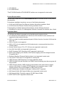
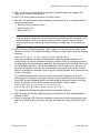
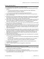
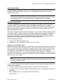
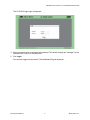
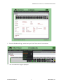
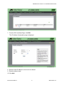
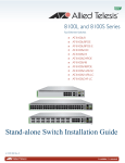
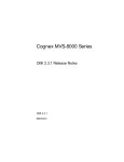
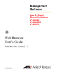
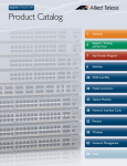
AlliedWare Plus™ Version 2.2.4.0 Release AT-8100S and AT-8100L Series Fast Ethernet EcoSwitches Software Release Notes This is a release of the AT-8100 Series AlliedWare Plus Management Software. Please read this document before you begin to use the management software. This document contains the following sections: “Supported Platforms” on page 1 “Product Documentation” on page 2 “Operational Notes” on page 2 “Stacking Operational Notes” on page 4 “Known Issues” on page 4 “Upgrading the Switch” on page 5 “Logging onto the Switch” on page 5 “Contacting Allied Telesis” on page 11 Caution The software described in this document may contain certain encryption/security or cryptographic functionality and for exporting those products/software, USA export restrictions apply as per 15 C.F.R. Part 730-772 (particularly Part 740.17). At present, as per United States of America’s export regulations our products/software cannot be exported to Cuba, Iran, North Korea, North Sudan, or Syria. If you wish to transfer this software outside the United States or Canada, please refer to export regulations of USA. Supported Platforms Version 2.2.4.0 Release of the AlliedWare Plus™ Management Software is supported on the following switches: AT-8100L/8 AT-8100L/8POE AT-8100S/24C AT-8100S/24 AT-8100S/24POE AT-8100S/16F8-SC AT-8100S/16F8-LC AT-8100S/24F-LC PN 613-001748 Rev A 1 AlliedWare Plus Version 2.2.4.0 Software Release Notes AT-8100S/48* AT-8100S/48POE* *The AT-8100S/48 and the AT-8100S/48POE switches are not supported in stack mode. Product Documentation See the Allied Telesis web site at www.alliedtelesis.com for the latest versions of the product documentation. For hardware installation instructions, see one of the following documents: 8100L and 8100S Series Fast Ethernet Switches Stand-alone Installation Guide 8100S Series Fast Ethernet Switches Stacking Installation Guide For descriptions of software features and procedures, see the following document: AlliedWare Plus Version 2.2.4 Management Software Command Line Interface User’s Guide Operational Notes The following operational notes apply to both standalone and stacked switches. AT-8100/48 and AT-8100/48PoE: AT-8100/48 and AT-8100/48PoE switch models are not supported in stack mode at this time. 802.1x: In order for multiple supplicant dynamic VLANs to function, the native VLAN must be set to VID 1. 802.1x: Re-auth is not supported. 802.1x: 802.1x is not supported on VLAN trunked ports or access ports that have Voice VLANs enabled. Access Control Lists on VTYs: VTY ACLs are not supported in stack mode. Auto-QoS: Auto-QoS is not supported in stack mode. DHCP Snooping: DHCP Snooping is NOT supported in stack mode. DSCP-queue mapping: Per interface, DSCP-queue mapping cannot be changed on stack IDs greater than 1. Enhanced Stacking: Enhanced Stacking feature is not supported in stack mode. Flow control: Flow control is not supported on combo ports. IGMP Snooping: IGMP Snooping is no longer enabled by default. IGMP Snooping: Only the first group in an IGMPv3 report containing more than one group will be processed. IGMP Snooping Querier: IGMP snooping querier should not be used if there is another querier on the network. If multiple AT-8100 switches are connected at Layer 2, IGMP snooping querier must only be enabled on ONE switch per VLAN. MAC Authentication: Multiple Host Dynamic VLANs are NOT supported. MAC-based VLANs: MAC-based VLANs are not supported in stack mode. MAC-based VLANs: The switch supports 256 MAC-based VLANs. MSTP: MSTP is NOT supported in stack mode. PN 613-001748 Rev A 2 Allied Telesis, Inc. AlliedWare Plus Version 2.2.4.0 Software Release Notes PoE+: The 8100 only supports 802.1at compliant Powered Devices that support LLDP negotiation (2-event is not supported). LACP: The 8100 supports a maximum of 8 LACP Groups. Web GUI: The web browser interface has been tested and found to be compatible with the following web browsers: — Microsoft Internet Explorer 7 and 8 — Mozilla Firefox 3.6.3 — Apple Safari 4.0.5 Note If you are using the Explorer 8 web browser and the pull-down menus in the switch’s web browser interface do not work, open the Internet Options window in the web browser, select the Security tab, and set the custom settings to medium-high. Then refresh your page. IGMP Snooping is disabled by default. When enabled, all unknown multicast traffic will be flooded prior to a join. To disable the flooding of unknown multicast traffic, issue the following command: awplus(config)# no ip igmp snooping flood-unknown-mcast Once this command is issued, all multicast traffic except reserved addresses 224.0.0.1 through 224.0.0.255 will be dropped until there is a specific IGMP join requesting access to the suppressed IPv4 multicast group destination. Note that all non-IPv4 multicast traffic, such as IPv6 Neighbor Discovery, will also be suppressed. Once an IGMP join is received on a given port, snooping will only copy the multicast data to the joined ports and any router or query port configured or detected. If there is no join, the multicast data will not be sent to the router or query ports. For multicast networks where there are sources at the network edge and no device is generating joins or reports, for example, multicast security cameras, the best solution is to leave IGMP snooping disabled (which is the default setting) and limit flooding on the edge ports. For example, you can use the following commands for a 48-port switch: awplus(config)# interface port1.0.1-port1.0.48 awplus(config)# switchport block egress-multicast This will allow all multicast data packets to flood to the uplink ports only. IGMP Snooping and VLANs: IGMP Snooping is not supported on MAC-based and 802.1x Dynamic VLANs. VLANs: If more than 255 VLANs are configured on the switch, they are not displayed in the web GUI or SNMP. However, you can view, edit, and delete more than 255 VLANs via the CLI. PN 613-001748 Rev A 3 Allied Telesis, Inc. AlliedWare Plus Version 2.2.4.0 Software Release Notes Stacking Operational Notes The following operational notes apply only to stacked switches: It is required that a full reboot of the entire stack be made after making any physical stack changes: — For optimum stack performance, convergence and recovery time, Allied Telesis recommends stacking no more than 3 switches. — Do not issue any commands into the console during stack discovery. When configuring a stack, make sure that the lowest ID in the stack is running the latest version of the firmware. Upon stack boot up, the firmware loaded on the master switch is automatically downloaded to all member switches unless one or more member switches are running a newer firmware version than the master switch. In this case, the stack will not form. Within a stack, you must assign each switch a unique Device ID. By default, the Device ID is set to 0 which means it is ineligible to participate in a stack. Device IDs of 1 through 8 are reserved for stacking operation. The Device ID of 0 is for standalone switches. If you have PoE switches in a hardware stack, make sure the master switch is a PoE switch. Failing to do this, may limit PoE functionality. After the stack becomes operational, the stack ID LED on the switches displays the switch ID number and flashes the master number every few seconds. This is normal behavior for the LEDs when the switches are operating in a stacked configuration. When powering up, the stack ID LED displays “b.” In the event that current master switch fails or is removed from the stack, the next lowest ID will take over as master. This change of mastership will take anywhere between 1-5 minutes depending on the size of your stack and configuration. During the new initialization interswitch traffic may be disrupted. Once the stack is reinitialized under the new master, full network connectivity will resume. In the event that a stack member should fail (power failure, cable disconnect, etc.) network connectivity may be temporarily disrupted: — In a stack of 3 or less switches, connectivity to and through the stack may be disrupted for up to 2 minutes. — In a stack of 4 or more switches, connectivity may be disrupted for up to 10 minutes. During this time, the stack may require and issue a full reboot to all members. For reliable IGMP snooping operation, multicast sources and routers should only be connected to the master switch. In 802.1x, multiple supplicant mode is not supported on stacked units. Known Issues The following issues are unresolved in the Version 2.2.4.0 Release: Hardware stacking: QoS error message is shown after save and reboot. This is only a display issue and does not affect QoS functionality. PoE: Disabling PoE on an individual port is retained after a reboot. RIP: Triggered updates are not functioning. Regardless of any change, RIP only sends the updated information in the next scheduled update. PN 613-001748 Rev A 4 Allied Telesis, Inc. AlliedWare Plus Version 2.2.4.0 Software Release Notes Upgrading the Switch You may upgrade your switch to Version 2.2.4.0 software using the command line interface. For instructions, see the AlliedWare Plus Version 2.2.4 Management Software Command Line Interface User’s Guide. Note Allied Telesis recommends rebooting the switch before you upgrade the software. If you are upgrading a stack, it is recommended that you upgrade each unit separately. Logging onto the Switch The switch is shipped from the factory using a configuration boot.cfg file (with a copy stored in the qstart.cfg file). This configuration has the Web interface enabled and the IP address 169.254.1.1/16 attached to vlan1 on all ports. If you delete the boot.cfg file and restart the switch, this restores the switch to its default configuration with the Web interface disabled and no IP address assigned to the switch. There are two ways to log into the AT-8100 switches. You can connect a Windows laptop directly to an Ethernet port on a switch and bring up the Web interface with the assigned IP address. Or, you can use a console port connection to log onto the Command Line Interface (CLI). Both procedures assume that you have installed the switch according to the directions in either the stand-alone or stacking installation guide under Product Documentation. See the following procedures: “Logging on to the Web Interface,” next “Logging on to the Command Line Interface (CLI)” on page 9 Logging on to the Web Interface Before you connect a laptop (or any PC with an Ethernet card) directly to an Ethernet port on the switch, you must disconnect the laptop from any other network. When a laptop is disconnected from a network, it is no longer connected to a DHCP server. By default, when a laptop is set to use DHCP and a DHCP address is not found, Windows assigns a random IP address in the 169.254.0.0/16 subnet. Or, you can manually configure your laptop with an IP address in the 169.254.0.0/16 subnet. After you log in to the switch, you need to change the default IP address and reconnect to your network. Note You have to supply the Ethernet cable to connect a laptop directly to the switch. The cable is not shipped with the switch. To log on to the Web interface with a direct connection to the switch and change the default IP address, do the following: 1. Connect a straight through twisted-pair cable to an Ethernet port on the switch. 2. Connect the other end of the straight through twisted-pair cable to a twisted-pair connector on your laptop. 3. Open a web browser on your laptop and enter the following: http://169.254.1.1/ PN 613-001748 Rev A 5 Allied Telesis, Inc. AlliedWare Plus Version 2.2.4.0 Software Release Notes The AT-8100S Login page is displayed. 4. When prompted, enter a username and password. The default settings are “manager” for the username and “friend” for the password. 5. Click Login. You are now logged into the switch. The Dashboard Page is displayed. PN 613-001748 Rev A 6 Allied Telesis, Inc. AlliedWare Plus Version 2.2.4.0 Software Release Notes 6. From the Dashboard Page, select the Layer 3 tab. Then select IPv4 Interfaces. The IPv4 Interfaces Page is displayed. PN 613-001748 Rev A 7 Allied Telesis, Inc. AlliedWare Plus Version 2.2.4.0 Software Release Notes 7. From the IPv4 Interfaces Page, click Edit. The IP Address Configuration page is displayed. 8. Enter the new IP address in xxx.xxx.xxx.xxx format. 9. Enter the subnet mask. 10. Click Add. PN 613-001748 Rev A 8 Allied Telesis, Inc. AlliedWare Plus Version 2.2.4.0 Software Release Notes Logging on to the Command Line Interface (CLI) When you log into the CLI for the first time, you need to delete the factory IP address of 169.254.1.1/16 and assign a new IP address that is valid for your network. You can also disable the Web interface if you are using stacking or for improved security. See the AlliedWare Plus Version 2.2.4 Management Software Command Line Interface User’s Guide for instructions on how to enable secure HTTPs for the Web interface. To log on to the CLI through the console port on the switch, do the following: 1. Connect the RJ-45 connector on the management cable to the Console port on the switch. The management cable is shipped with the switch. 2. Connect the other end of the cable to an RS-232 port on a terminal or PC with a terminal emulator program. 3. Configure the terminal or terminal emulator program as follows: — Baud rate: 9600 — Data bits: 8 — Parity: None — Stop bits: 1 — Flow control: None 4. Press Enter. You are prompted for a user name and password. 5. Enter “manager” for the username and “friend” for the password. The local management session is started when the AlliedWare Plus command line prompt is displayed. awplus> 6. To delete the current IP address and disable the Web interface, you can either delete the startup configuration file (boot.cfg) and then reboot the switch or enter the commands individually. To delete the startup.cfg file and reboot the switch, enter the following commands: awplus> enable awplus# erase Erase startup config? (y/n): y awplus# reboot To delete the current IP address and disable the Web interface, enter: awplus> enable PN 613-001748 Rev A 9 Allied Telesis, Inc. AlliedWare Plus Version 2.2.4.0 Software Release Notes awplus# configure terminal awplus(config)# interface vlan1 awplus(config-if)# no ip address awplus(config-if)# exit awplus(config)# no service http 7. To assign a new IP address and subnet mask to the switch (for example, 167.142.10.5/16), enter the following commands: awplus> enable awplus# configure terminal awplus(config)# interface vlan1 awplus(config-if)# ip address 167.142.10.5/16 8. To confirm the new IP address has been assigned to the switch, enter the following commands: awplus(config-if)# end awplus# show ip interface 9. To save your changes by updating the startup configuration file (boot.cfg) with the switch’s current configuration, enter the following command: awplus# write PN 613-001748 Rev A 10 Allied Telesis, Inc. AlliedWare Plus Version 2.2.4.0 Software Release Notes Contacting Allied Telesis This section provides Allied Telesis contact information for technical support as well as sales or corporate information. Online Support You can request technical support online by accessing the Allied Telesis Knowledge Base at www.alliedtelesis.com/support. You can use the Knowledge Base to submit questions to our technical support staff and review answers to previously asked questions. Email and Telephone Support For Technical Support via email or telephone, refer to the Support & Services section of the Allied Telesis web site: www.alliedtelesis.com/support. Select your country from the list displayed on the website. then select the appropriate menu tab. Warranty For hardware warranty information, refer to the Allied Telesis web site at www.alliedtelesis.com/support/warranty. Returning Products Products for return or repair must first be assigned a return materials authorization (RMA) number. A product sent to Allied Telesis without an RMA number will be returned to the sender at the sender’s expense. To obtain an RMA number, contact the Allied Telesis Technical Support group at our web site: www.alliedtelesis.com/support/rma. Select your country from the list displayed on the website. Then select the appropriate menu tab. Sales or Corporate Information You can contact Allied Telesis for sales or corporate information through our web site: www.alliedtelesis.com/purchase/direct. To find an office near you, select www.alliedtelesis.com/office. Management Software Updates New releases of management software for our managed products are available on our Allied Telesis web site at http://www.alliedtelesis.com/support/software. Copyright © 2012 Allied Telesis, Inc. All rights reserved. No part of this publication may be reproduced without prior written permission from Allied Telesis, Inc. Allied Telesis and AlliedWare Plus are trademarks of Allied Telesis, Inc. All other product names, company names, logos or other designations mentioned herein are trademarks or registered trademarks of their respective owners. Allied Telesis, Inc. reserves the right to make changes in specifications and other information contained in this document without prior written notice. The information provided herein is subject to change without notice. PN 613-001748 Rev A 11 Allied Telesis, Inc.