1
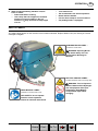
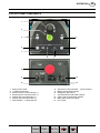
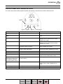
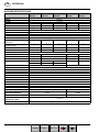
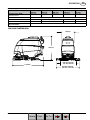
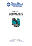
TENNANT T5
SCRUBBER DRYER
OPERATOR MANUAL
Clemas & Co. Unit 5 Ashchurch Business Centre, Alexandra Way, Tewkesbury,
Gloucestershire, GL20 8NB.
Tel: 01684 850777
Fax: 01684 850707
Email: [email protected]
Web: www.clemas.co.uk
OPERATION
EN
TABLE OF CONTENTS
SAFETY PRECAUTIONS . . . . . . . . . . . . . . . . . . . .
4
SAFETY LABELS . . . . . . . . . . . . . . . . . . . . . . . . . . .
5
MACHINE COMPONENTS . . . . . . . . . . . . . . . . . . .
6
CONTROL PANEL COMPONENTS . . . . . . . . . . .
7
MACHINE INSTALLATION . . . . . . . . . . . . . . . . . . .
UNCRATING MACHINE . . . . . . . . . . . . . . . . . .
INSTALLING BATTERIES . . . . . . . . . . . . . . . .
8
8
8
HOW THE MACHINE WORKS . . . . . . . . . . . . . . .
9
BRUSH AND PAD INFORMATION . . . . . . . . . . . .
9
MACHINE SETUP . . . . . . . . . . . . . . . . . . . . . . . . . .
ATTACHING SQUEEGEE ASSEMBLY . . . . .
INSTALLING BRUSHES/PADS . . . . . . . . . . . .
INSTALLING FAST--PAK CARTON . . . . . . . .
FILLING SOLUTION TANK . . . . . . . . . . . . . . .
9
9
10
11
11
MACHINE OPERATION . . . . . . . . . . . . . . . . . . . . .
PRE--OPERATION CHECKS . . . . . . . . . . . . . .
STARTING THE MACHINE . . . . . . . . . . . . . . .
EMERGENCY STOPPING . . . . . . . . . . . . . . . .
WHILE OPERATING MACHINE . . . . . . . . . . .
BATTERY CHARGE LEVEL INDICATOR . . .
HOUR METER . . . . . . . . . . . . . . . . . . . . . . . . . .
OFF--AISLE WAND OPERATION . . . . . . . . . .
12
12
12
13
13
14
14
14
DRAINING AND CLEANING TANKS . . . . . . . . . .
DRAINING RECOVERY TANK . . . . . . . . . . . .
DRAINING SOLUTION TANK . . . . . . . . . . . . .
15
15
16
CHARGING BATTERIES . . . . . . . . . . . . . . . . . . . .
BATTERY CHARGER SPECIFICATIONS . . .
ON--BOARD BATTERY CHARGER
SETTINGS . . . . . . . . . . . . . . . . . . . . . . . . . . . .
USING THE ON--BOARD BATTERY
CHARGER . . . . . . . . . . . . . . . . . . . . . . . . . . . .
ON--BOARD BATTERY CHARGER ERROR
CODES . . . . . . . . . . . . . . . . . . . . . . . . . . . . . . .
USING AN OFF--BOARD BATTERY
CHARGER . . . . . . . . . . . . . . . . . . . . . . . . . . . .
16
16
ADJUSTING SCRUB HEAD BRUSHES . . . . . . .
DISK MODEL . . . . . . . . . . . . . . . . . . . . . . . . . . .
CYLINDRICAL BRUSH MODEL . . . . . . . . . . .
19
19
19
MACHINE MAINTENANCE . . . . . . . . . . . . . . . . . .
DAILY MAINTENANCE . . . . . . . . . . . . . . . . . . .
MONTHLY MAINTENANCE . . . . . . . . . . . . . . .
BATTERY MAINTENANCE . . . . . . . . . . . . . . .
SQUEEGEE BLADES . . . . . . . . . . . . . . . . . . . .
MOTOR MAINTENANCE . . . . . . . . . . . . . . . . .
FAST SYSTEM MAINTENANCE . . . . . . . . . .
21
21
23
24
24
25
25
JACKING UP MACHINE . . . . . . . . . . . . . . . . . . . . .
26
TRANSPORTING MACHINE . . . . . . . . . . . . . . . . .
26
STORING MACHINE . . . . . . . . . . . . . . . . . . . . . . . .
26
RECOMMENDED STOCK ITEMS . . . . . . . . . . . . .
26
TROUBLESHOOTING . . . . . . . . . . . . . . . . . . . . . . .
27
CONTROL PANEL FAULT INDICATOR CODES
29
MACHINE SPECIFICATIONS . . . . . . . . . . . . . . . .
30
16
17
18
18
3
Tennant T5 (06--06)
Home
Find... Go To..
EN
OPERATION
FOR SAFETY:
SAFETY PRECAUTIONS
This machine is intended for industrial and
commercial use. It is designed exclusively to scrub
hard floors in an indoor environment and is not
constructed for any other use. Only use
recommended pads, brushes and commercially
approved floor cleaners intended for machine
application.
The following warning alert symbol and the “FOR
SAFETY” heading are used throughout this manual as
indicated in their description:
WARNING: To warn of hazards or unsafe
practices which could result in severe personal
injury or death.
FOR SAFETY: To identify actions which must be
followed for safe operation of equipment.
The following safety precautions signal potentially
dangerous conditions to the operator or
equipment. All operators must read, understand
and practice them.
WARNING: Fire Or Explosion Hazard
--
Never Use Flammable Liquids Or Operate
Machine In Or Near Flammable Liquids, Vapors
Or Combustible Dusts.
This machine is not equipped with explosion proof
motors. The electric motors will spark upon start
up and during operation which could cause a flash
fire or explosion if machine is used in an area
where flammable vapors/liquids or combustible
dusts are present.
--
Do Not Pick Up Flammable Materials Or
Reactive Metals.
--
Batteries Emit Hydrogen Gas. Keep Sparks And
Open Flame Away. Keep Battery Compartment
Open When Charging.
WARNING: Electrical Hazard
--
Disconnect Battery Cables and Charger Plug
Before Servicing Machine.
--
Do Not Charge Batteries with Damaged Power
Supply Cord. Do Not Modify Plug.
If the charger supply cord is damaged or broken, it
must be replaced by the manufacturer or its
service agent or a similarly qualified person in
order to avoid a hazard.
1. Do not operate machine:
-- With flammable liquids or near flammable
vapors as an explosion or flash fire may
occur.
-- Unless trained and authorized.
-- Unless operator manual is read and
understood.
-- If not in proper operating condition.
2. Before starting machine:
-- Make sure all safety devices are in place
and operate properly.
3. When using machine:
-- Go slow on inclines and slippery surfaces.
-- Wear non--slip shoes.
-- Reduce speed when turning.
-- Report machine damage or faulty operation
immediately.
-- Never allow children to play on or around.
-- Follow mixing and handling instructions on
chemical containers.
-- Do not operate on inclines that exceed 5%
(3°).
4. Before leaving or servicing machine:
-- Stop on level surface.
-- Turn off machine.
-- Set parking brake, if equipped.
-- Remove key.
5. When servicing machine:
-- Avoid moving parts. Do not wear loose
jackets, shirts, or sleeves.
-- Disconnect battery cables and charger plug
before working on machine.
-- Wear protective gloves and eye protection
when handling batteries or battery cables.
-- Avoid contact with battery acid.
-- Do not power spray or hose off machine.
Electrical malfunction may occur.
-- Jack machine up at designated locations
only (See JACKING UP MACHINE).
-- Use hoist or jack that will support machine
weight.
-- Use manufacturer supplied or approved
replacement parts.
-- All repairs must be performed by a
qualified service person.
-- Do not modify the machine from its original
design.
WARNING: Spinning Brush. Keep Hands
Away. Turn Off Power Before Working On Machine.
4
Tennant T5 (06--06)
Home
Find...
Go To..
OPERATION
6. When loading/unloading machine onto/off
truck or trailer:
-- Drain tanks before loading.
-- Use a ramp that can support the machine
weight and person loading it. Do not
exceed a 11° ramp incline at a ramp length
of 3.7m.
------
EN
Turn machine off.
Put scrub head in the lowered position.
Block machine wheels.
Use tie--down straps to secure machine.
Set parking brake, if equipped.
SAFETY LABELS
The safety labels appear on the machine in the locations indicated. Replace labels if they are missing or become
damaged or illegible.
SPINNING BRUSH LABEL Located on scrub head
WARNING: Spinning Brush.
Keep Hands Away. Turn Off
Power Before Working On
Machine.
BATTERY CHARGE LABEL -Located at bottom side of recovery tank.
WARNING: Fire Or Explosion
Hazard. Batteries Emit Hydrogen
Gas. Keep Sparks And Open
Flame Away. Keep Battery
Compartment Open When
Charging.
READ MANUAL LABEL -Located on recovery tank cover.
FOR SAFETY: Do not operate
machine unless operation
manual is read and understood.
5
Tennant T5 (06--06)
Home
Find...
Go To..
EN
OPERATION
MACHINE COMPONENTS
13
14
15
16
28
1
2
15
17
21
20
3
19
18
6
4
7
22
8
5
9
23
27
10
25
24
11
12
1.
2.
3.
4.
5.
6.
7.
8.
9.
10.
11.
12.
13.
14.
15.
16.
17.
18.
19.
20.
Control Handle
Control Handle Start Bail
Upper & Lower Control Panels
Recovery Tank Drain Hose
On--board Battery Charger
Squeegee Lift Lever
Rear Fill-Port
Solution Tank Level/Drain Hose
Squeegee Vacuum hose
Wall Rollers
Squeegee Assembly
Solution Tank Clean-Out Port
Recovery Tank Support Stand
Control Board
Bucket Fill Port/Clean--out Port
FaST--PAK Carton Compartment
Batteries
Off--Aisle Wand Solution Hose Coupler
Recovery Tank
Recovery Tank Cover
26
21.
22.
23.
24.
25.
26.
27.
28.
Cup Holder
Solution Tank
Disk Scrub Head
Pad Release Plunger
Pad Driver Window
Scrub Head Skirt
Parking Brake
Cylindrical Brush Scrub Head
6
Tennant T5 (06--06)
Home
Find...
Go To..
OPERATION
EN
CONTROL PANEL COMPONENTS
1
2
3
5
4
6
7
8
9
10
1.
2.
3.
4.
5.
6.
7.
11
13
12
14
Speed control knob
1--STEP scrub button
Brush pressure increase button (+)
Brush pressure decrease button (--)
Solution flow increase button (+)
Solution flow decrease button (--)
Fault indicator -- Contact Service
8.
9.
10.
11.
12.
13.
14.
Supervisor Control indicator -- Lockout feature
Battery charge level indicator
Emergency stop button
Off--Aisle wand on/off switch (option)
FaST system on/off switch (option)
Main power on/off key switch
Hour meter
7
Tennant T5 (06--06)
Home
Find...
Go To..
EN
OPERATION
MACHINE INSTALLATION
UNCRATING MACHINE
1. Carefully check the shipping crate for signs of
damage. Report damage at once to carrier.
2. Check the contents list. Contact distributor for
missing items.
Contents:
S 4--6 V Batteries--Optional
S 3--Battery Cable Jumpers
S Battery Tray
S 1--FaST--PAK 365 Concentrate--Optional
S Squeegee Assembly
S 2--Pad drivers (Disk Model)
S 2--Brushes (Cylindrical Brush Model)
FIG. 1
3. Carefully install the batteries into the battery
compartment tray (Figure 2). Arrange the battery
posts as shown (Figure 3).
3. To uncrate your machine, remove the shipping
hardware and straps that secure the machine to
the pallet. Carefully back machine down ramp.
ATTENTION: Do not roll machine off pallet unless a
ramp is used, machine damage may occur.
ATTENTION: To prevent possible machine damage,
install batteries after removing machine from
shipping pallet.
FIG. 2
INSTALLING BATTERIES
WARNING: Fire Or Explosion Hazard.
Batteries Emit Hydrogen Gas. Keep Sparks And
Open Flame Away. Keep Battery Hood Open When
Charging.
4. Connect the battery cables to the battery posts as
shown (Figure 3), RED TO POSITIVE (+) and
BLACK TO NEGATIVE (--).
180A/5H
200A/5H
FOR SAFETY: When installing batteries, wear
protective gloves and eye protection. Avoid
contact with battery acid.
BLACK
Battery Specifications:
Four 6 volt,180A/5h or 200A/5h deep cycle batteries.
Maximum battery dimensions:
190 mm W x 275 mm L x 284 mm H.
Machine
Front
RED
1. Park the machine on a level surface, remove the
key and set the parking brake.
2. Lift the recovery tank and remove the right side
battery compartment panel (Figure 1). 13mm
wrench required.
FIG. 3
IMPORTANT: If your machine is equipped with the
on--board battery charger, make sure that the
charger is properly set for your battery type before
charging (See ON--BOARD CHARGER SETTINGS).
8
Tennant T5 (06--06)
Home
Find...
Go To..
OPERATION
HOW THE MACHINE WORKS
EN
MACHINE SETUP
Conventional Scrubbing:
Water and detergent from the solution tank flow to the
floor through a solution valve. The brushes use the
detergent and water to scrub the floor clean. As the
machine moves forward, the squeegee wipes the dirty
solution from the floor into the recovery tank.
Foam Scrubbing (FaST Model):
(FaST--Foam activated Scrubbing Technology)
Unlike conventional scrubbing, the FaST system injects
the FaST--PAK concentrate formula with a small
amount of water and air onto the floor. The mixture
creates a large volume of expanded wet foam for the
brush to scrub the floor clean. As the machine moves
forward, the foam collapses and the squeegee
recovers the dirty solution into the the recovery tank
leaving the floor clean dry and slip free.
ATTACHING SQUEEGEE ASSEMBLY
1. Park the machine on a level surface, remove the
key and set the parking brake if equipped.
2. Lift the squeegee lift lever to the upward position
(Figure 4).
BRUSH AND PAD INFORMATION
FIG. 4
For best cleaning results use the appropriate brush
type for your cleaning application. Refer to the Parts
manual for part number information.
3. Mount the squeegee assembly to the squeegee
pivot bracket and secure with knobs (Figure 5).
Polypropylene Bristle Scrub Brush (Black) -This general purpose polypropylene bristle scrub brush
is used for scrubbing lightly compacted soilage. This
brush works well for maintaining concrete, wood and
grouted tile floors.
Soft Nylon Bristle Scrub Brush (White) -Recommended for cleaning coated floors without
removing finish. Cleans without scuffing.
Super Abrasive Bristle Scrub Brush (Gray) -Nylon fiber impregnated with abrasive grit to remove
stains and soilage. Strong action on any surface.
Performs well on buildup, grease, or tire marks.
Polishing Pad (White) -Used to maintain highly polished or burnished floors.
FIG. 5
4. Connect the vacuum hose to the squeegee
assembly. Loop the hose as shown using the hose
clip provided (Figure 6).
Buffing Pad (Red) -- Used for light duty scrubbing
without removing floor finish.
Scrubbing Pad (Blue) -- Used for medium to
heavy--duty scrubbing. Removes dirt, spills, and scuffs
and leaves surface clean ready for recoating.
Stripping Pad (Brown) -- Used for stripping of floor
finish to prepare the floor for recoating.
Heavy Duty Stripping Pad (Black) -- Used for
aggressive stripping of heavy finishes/sealers, or very
heavy duty scrubbing.
FIG. 6
9
Tennant T5 (06--06)
Home
Find...
Go To..
EN
OPERATION
5. Check the squeegee blades for proper deflection.
The blades should deflect as shown (Figure 7).
3. Align the pad driver under the motor hub and push
it upward to engage (Figure 10).
FIG. 7
FIG. 10
6. To adjust the blade deflection, place the squeegee
assembly on a level surface and adjust the casters
as shown (Figure 8).
4. To remove the pad driver, raise the scrub head and
push the pad release plunger downward
(Figure 11).
2 mm
Lock Nut
FIG. 8
FIG. 11
5. Check the scrub head to ensure that it is properly
adjusted (See ADJUSTING SCRUB HEAD
BRUSHES).
INSTALLING BRUSHES/PADS
FOR SAFETY: Before installing brushes, stop
machine on level surface, remove key and set
parking brake if equipped.
Cylindrical Brush Model:
1. Raise scrub head off the floor and remove key.
2. Remove idler plate from scrub head by pressing
the spring tab downward (Figure 12).
Disk Model:
1. Raise scrub head off the floor and remove key.
2. Attach the pad to the pad driver before installing
the driver. Secure pad with centerlock (Figure 9).
FIG. 12
3. Attach idler plate to the brush end that has the
double row of bristles (Figure 13). Install brush.
FIG. 9
10
Tennant T5 (06--06)
Home
Find...
Go To..
OPERATION
EN
3. When the supply hose is not in use, connect the
storage plug to prevent the FaST system from
drying out and clogging up the hose. (Figure 16).
Double row of
bristles
FIG. 13
4. Check the brushes to ensure they are properly
adjusted (See ADJUSTING SCRUB HEAD
BRUSHES).
FIG. 16
INSTALLING FaST--PAK CARTON (FaST Model)
FILLING SOLUTION TANK
ATTENTION: The FaST--PAK Concentrate Formula
is specifically designed for the FaST system.
NEVER use a substitute. Machine damage may
result.
Using a hose or bucket, fill the solution tank to the
“MAX 85L” mark (Figure 17).
1. Pull out the hose connector from the FaST--PAK
carton and remove cap (Figure 14).
For FaST Scrubbing: Use cool clean water only (less
than 21°C). Do not add any conventional floor cleaning
detergents, FaST system failure may result.
For Conventional Scrubbing: Use hot water (60°C
maximum). Pour a recommended cleaning detergent
into the solution tank according to mixing instructions
on the container.
FIG. 14
2. Open the battery compartment. Connect the
FaST--PAK carton to the supply hose and place
carton in compartment (Figure 15). Make sure the
hose does not get pinched.
FIG. 17
ATTENTION: For conventional scrubbing, only use
commercially approved cleaning detergents.
Machine damage due to improper detergent usage
will void the manufacturer’s warranty.
WARNING: Fire or Explosion Hazard.
Never Use Flammable Liquids.
FIG. 15
11
Tennant T5 (06--06)
Home
Find...
Go To..
EN
OPERATION
MACHINE OPERATION
FOR SAFETY: Do not operate machine, unless
operator manual is read and understood.
WARNING: Fire Or Explosion Hazard. Never
Operate Machine In Or Near Flammable Liquids,
Vapors Or Combustible Dusts.
PRE--OPERATION CHECKS
FIG. 19
- Sweep area.
4. Lower the squeegee assembly to floor by lowering
the squeegee lift lever (Figure 20).
- Check the battery charge level indicator.
- Check the brushes/pads for wear.
- Check the squeegee blades for wear and proper
adjustment.
- Make sure the recovery tank is empty and the float
shut--off screen is installed and clean.
- Check the scrub head skirt for wear.
- Foam Scrubbing (FaST model): Check the
FaST--PAK concentrate level.
- Foam Scrubbing (FaST model): Make sure the
solution tank is filled with cool clean water only.
- Foam Scrubbing (FaST model): Ensure that all
conventional cleaning agents are drained and
rinsed from solution tank.
FIG. 20
5. Press the 1--STEP scrub button (Figure 21).
STARTING THE MACHINE
1. Release the parking brake if equipped (Figure 18).
2. Turn the key to the on ( I ) position (Figure 18).
FIG. 21
6. Pull the control handle bail to start scrubbing
(Figure 22). To reverse the machine, simply push
the control handle bail forward. Raise squeegee
when reversing machine.
FIG. 18
3. To foam scrub (FaST model), press the FaST
system switch to the on ( I ) position (Figure 19).
IMPORTANT: NEVER turn the FaST system switch on
when conventional scrubbing. Conventional cleaning
detergents/restorers may cause failure to the FaST
injection system. Drain, rinse and refill solution tank
with cool clean water before operating the FaST
system.
12
Tennant T5 (06--06)
Home
Find...
Go To..
OPERATION
EN
EMERGENCY STOPPING
Strike the emergency stop button, if equipped, in the
event of an emergency (Figure 25). This button shuts
off all power to machine. Turn the button clockwise and
restart the key to regain power.
FIG. 22
7. Adjust the speed control knob to a desired
scrubbing speed (Figure 23).
NOTE: 45--60 meters per minute is the recommended
scrubbing speed.
FIG. 25
WHILE OPERATING MACHINE
WARNING: Fire Or Explosion Hazard. Do Not
Pick Up Flammable Materials Or Reactive Metals.
1. Overlap each scrub path by 5 cm.
2. Keep the machine moving to prevent damage to
floor finish.
3. Do not operate the machine on inclines that exceed
FIG. 23
5% (3°).
8. Press the brush pressure and solution flow buttons
to increase (+) or decrease (--) as needed (Figure
24). To shut off the solution flow, continue to press
the decrease button (--) until the lights turn off.
4. Conventional scrubbing: Pour a commercially
approved foam control solution into the recovery
tank if excessive foam appears.
NOTE: When foam scrubbing (FaST), the solution flow
lights will not light up. The FaST system solution flow
rate is fixed and requires no adjustment.
ATTENTION: Do not allow foam to enter the float
shut-off screen, vacuum motor damage will result.
Foam will not activate the float shut-off screen.
5. For heavily soiled areas, use the double scrubbing
method. First scrub the area with the squeegee up,
let solution set for 3--5 minutes, then scrub the area
a second time with squeegee down.
6. When leaving the machine unattended, remove the
key and set the parking brake, if equipped.
7. If the machine detects a fault, the control panel
lights will blink a fault code (See CONTROL
PANEL FAULT INDICATOR CODES).
FIG. 24
9. To stop scrubbing, release the control handle bail,
press the 1--STEP scrub button and raise the
squeegee.
13
Tennant T5 (06--06)
Home
Find...
Go To..
EN
OPERATION
BATTERY CHARGE LEVEL INDICATOR
OFF--AISLE WAND SETUP AND OPERATION
The battery charge level indicator displays the charge
level of the batteries (Figure 26). When the batteries
are fully charged, all five indicator lights will glow. As
the batteries discharge, the indicator lights will begin to
go out from right to left.
If your machine is equipped with the off--aisle wand
option, this allows you to scrub areas where the
machine is unable to reach.
When the discharge level reaches the red light, the
operator will have approximately one minute to
continue scrubbing. When the red light begins to flash
the scrubbing functions will automatically shut off to
alert the operator to recharge the batteries. By pressing
the 1--STEP Scrub button, when the red light is
flashing, the operator will get an additional minute of
scrubbing.
1. Park the machine on a level surface, turn key off
and set parking brake if equipped.
Preparing Machine for Off--Aisle Wand Scrubbing:
2. Connect the solution hose to the coupler at the
lower right side of machine (Figure 28).
FIG. 28
3. Using the hose adapter, connect the squeegee
hose to the wand hose (Figure 29).
FIG. 26
HOUR METER
The hour meter records the number of total hours the
vacuum and brush motors have been powered on. Use
the hour meter to determine when to perform
recommended maintenance procedures and to record
service history (Figure 27). See MOTOR
MAINTENANCE.
FIG. 29
4. Attach the off--aisle wand to the hoses (Figure 30).
FIG. 27
FIG. 30
14
Tennant T5 (06--06)
Home
Find...
Go To..
OPERATION
EN
Operating the Off--Aisle Wand:
1. Turn the key and wand switch to the on ( I )
position (Figure 31). The FaST system switch is
disabled when operating the wand.
DRAINING AND CLEANING TANKS
After each use, the tanks should be drained and cleaned.
DRAINING RECOVERY TANK
1. Transport machine to disposal area and turn key
switch off.
2. While holding the drain hose upward, remove the
cap and lower hose to drain (Figure 34).
FIG. 31
2. Lower the squeegee to activate the vacuum motor
(Figure 32).
FIG. 34
3. After draining, open the recovery tank and clean
out the tank (Figure 35).
FIG. 32
3. Squeeze trigger to activate solution. Use brush for
scrubbing and squeegee for pickup (Figure 33).
FIG. 35
4. Clean the float shut-off screen and debris tray
located in the recovery tank (Figure 36).
FIG. 33
4. After scrubbing, turn off the wand switch and
squeeze the trigger for five seconds to relieve the
water pressure before disconnecting the solution
hose.
FIG. 36
WARNING: Fire or Explosion Hazard. Do Not
Pick Up Flammable Materials Or Reactive Metals.
15
Tennant T5 (06--06)
Home
Find...
Go To..
EN
OPERATION
DRAINING SOLUTION TANK
CHARGING BATTERIES
1. To drain remaining water from the solution tank,
pull the solution tank level hose off the hose fitting
(Figure 37).
ATTENTION: To prolong the life of the batteries
only recharge the batteries if the machine was
used for a total of 30 minutes or more. Do not leave
batteries discharged for lengthy periods.
WARNING: Fire Or Explosion Hazard.
Batteries Emit Hydrogen Gas. Keep Sparks And
Open Flame Away. Keep Battery Compartment
Open When Charging.
FOR SAFETY: When servicing batteries, wear
protective gloves and eye protection when
handling batteries and battery cables. Avoid
contact with battery acid.
FIG. 37
2. To rinse out the solution tank remove the clean--out
cap at the rear of the machine and spray water
directly into the clean-out ports (Figure 38).
BATTERY CHARGER SPECIFICATIONS:
S
CHARGER TYPE:
-- FOR SEALED (Gel) BATTERIES
-- FOR WET (Lead acid) BATTERIES
S
S
S
S
OUTPUT VOLTAGE - 24 VOLTS
OUTPUT CURRENT - 20 AMPS
AUTOMATIC SHUTOFF CIRCUIT
FOR DEEP CYCLE BATTERY CHARGING
ON--BOARD BATTERY CHARGER SETTINGS:
If your machine is equipped with the on--board charger,
the charger settings must be set for your battery type,
Wet/lead acid or sealed/Gel, before charging. Failure to
properly set will result in battery damage.
FIG. 38
3. Clean the solution tank filter (Figure 39).
To determine your battery type, see battery label.
Contact your battery supplier if not specified.
To verify what the charger is currently for, connect the
charger cord into an electrical receptacle. The charger
will display a sequence of codes. One of the codes will
either read “GEL” or “Acd” (Figure 40).
GEL = Set for sealed/maintenance free batteries
Acd = Set for wet/lead acid batteries
FIG. 39
FIG. 40
16
Tennant T5 (06--06)
Home
Find...
Go To..
OPERATION
To change the setting, unplug the charger, peel up the
corner of the display label and set the switches
accordingly (Fig. 41). The charger cord must be
unplugged when resetting.
EN
NOTE: The machine will not operate when charging.
FIG. 43
SEALED “GEL” BATTERY
WET “Acd” BATTERY
FIG. 41
USING THE ON--BOARD BATTERY CHARGER
IMPORTANT: Before charging, make sure that the
charger setting is properly set for your battery type
(See ON--BOARD CHARGER SETTINGS).
1. Transport the machine to a well--ventilated area.
6. The charger will display a sequence of codes once
the cord is connected (Figure 44).
Three--digits + the following code:
A = Charging current
U = Battery Voltage
h = Charging time
C = Charging ampere--hours [Ah]
E = Energy used [Kwh]
“GEL” or “Acd” = Battery type the charger is
currently set for. Before charging make sure
your battery type matches the display:
GEL=Sealed, Acd=WET (lead acid). To change
setting, see ON--BOARD CHARGER
SETTINGS.
Press the arrow button to review the codes.
2. Park the machine on a flat, dry surface. Turn the
key off and set the parking brake, if equipped.
3. If charging wet (lead acid) batteries check the fluid
level before charging (See BATTERY
MAINTENANCE).
4. Prop up the recovery tank for ventilation
(Figure 42).
FIG. 44
7. Once the charging cycle begins, the indicator lights
will progress from red, yellow to green. When the
green indicator light comes on, the charging cycle
is done. Unplug the charger cord.
If the charger detects a problem, the charger will
display an error code (See ON--BOARD BATTERY
CHARGER ERROR CODES).
FIG. 42
5. Connect the charger’s AC power supply cord into a
properly grounded receptacle (Figure 43).
17
Tennant T5 (09--06)
Home
Find...
Go To..
EN
OPERATION
ON--BOARD BATTERY CHARGER ERROR CODES
DISPLAY CODE
FAULT
SOLUTION
bat
Loose or damaged battery cable
Check battery cable connections.
Battery exceeded maximum voltage level.
No action necessary.
E01
Exceeded maximum battery voltage allowed.
No action necessary.
E02
Safety thermostat exceeded maximum
internal temperature.
Check if the charger vents are obstructed.
E03
Exceeded maximum time for charging phase
leaving the batteries undercharged due to a
sulfated or faulty battery.
Repeat the charging cycle and if the error
code E03 reappears check battery or
replace it.
SCt
Safety timer exceeded maximum charging
time. Interrupts charging cycle.
Replace battery.
Srt
Possible internal short circuit.
Contact Service Center.
USING AN OFF--BOARD BATTERY CHARGER
(OPTION)
1. Transport the machine to a well--ventilated area.
2. Park the machine on a flat, dry surface. Turn the
key off and set the parking brake, if equipped.
3. If charging wet (lead acid) batteries, check the fluid
level before charging (See BATTERY
MAINTENANCE).
4. Prop up the recovery tank for ventilation
(Figure 45).
FIG. 46
7. The supplied charger will automatically begin
charging and shut off when fully charged.
NOTE: The machine will not operate when charging.
ATTENTION: Do not disconnect the charger’s DC
cord from the machine’s receptacle when the
charger is operating. Arcing may result. If the
charger must be interrupted during charging,
disconnect the AC power supply cord first.
FIG. 45
5. Connect the charger’s AC power supply cord into a
properly grounded receptacle.
6. Connect the charger’s DC cord into the machine’s
battery receptacle (Figure 46).
18
Tennant T5 (06--06)
Home
Find...
Go To..
OPERATION
EN
ADJUSTING SCRUB HEAD BRUSHES
CYLINDRICAL BRUSH MODEL
To ensure optimum scrubbing performance periodically
check the scrub head for proper adjustment.
After installing a new set of cylindrical brushes check
the brush pattern to ensure proper brush adjustment.
Brushes that are not properly adjusted will result in
premature wear and poor scrubbing performance
(Figure 49).
FOR SAFETY: Before adjusting scrub head, stop
machine on level surface, remove key and set
parking brake if equipped.
CORRECT BRUSH PATTERN
Even
Pattern
DISK MODEL
Tools required: Measuring device, 27mm wrench and
24mm wrench
Uneven
Pattern
INCORRECT BRUSH PATTERNS
Tapered
Pattern
1. With brushes installed, lower the scrub head and
apply medium brush pressure.
2. Turn machine off and remove key.
3. From the center front and back of scrub head,
measure the distance from the top edge of scrub
head to the floor (Figure 47).
FIG. 49
To Inspect the Brush Pattern:
1. Position the machine on a dry dusty floor or apply a
powdered substance, such as chalk.
2. Disconnect the drive motor wire connector to keep
machine from moving forward (Figure 50).
FIG. 47
4. If scrub head is not level, loosen the lock nut and
turn the scrub head leveling screw to level. Tighten
down the lock nut once head is level (Figure 48).
FIG. 50
3. Lower the scrub head to the floor and apply
maximum brush pressure.
4. Shut off the solution flow.
5. Pull the control handle bail to create a brush
pattern on the floor.
Lock
Nut
6. Raise the scrub head and pull the machine away.
7. Observe the brush pattern on floor. If the brush
pattern is uneven or tapered, adjustment is
required.
FIG. 48
8. Reconnect drive motor wire.
19
Tennant T5 (06--06)
Home
Find...
Go To..
EN
OPERATION
To Adjust an Uneven Brush Pattern:
To Adjust a Tapered Brush Pattern:
Tools required: Measuring device, 27mm wrench and
24mm wrench
Tools required: 10mm wrench and 6mm hex wrench
1. Measure the distance from the front edge of the
scrub head to the floor and from the back edge of
the scrub head to the floor (Figure 51). The
measurements should be the same.
1. Raise the scrub head off floor and remove key.
2. Remove the idler plate from the brush (Figure 53).
FIG. 53
3. Hold the brush plug shaft with a wrench and loosen
the 6mm hex screw (Figure 54).
FIG. 51
2. To level the scrub head, loosen the lock nut and
turn the leveling screw clockwise to lower the rear
of the scrub head or counter--clockwise to lower the
front (Figure 52).
FIG. 54
4. To lower the brush end, turn the shaft clockwise for
the front brush and counter--clockwise for the rear
brush. Retighten hex screw (Figure 55).
FIG. 52
3. Recheck brush pattern.
NOTE: Replace brushes when worn to 15mm.
FIG. 55
5. Recheck brush pattern.
NOTE: Replace brushes when worn to 15mm.
20
Tennant T5 (06--06)
Home
Find...
Go To..
OPERATION
EN
4. Remove the debris tray and empty (Figure 59)
MACHINE MAINTENANCE
To keep the machine in good working condition, it’s
important that the following maintenance procedures
are performed on a routine basis.
WARNING: Electrical Hazard. Disconnect
Battery Cables Before Servicing Machine.
DAILY MAINTENANCE (After Every Use)
1. Drain the recovery tank (Figure 56).
FIG. 59
5. Drain the solution tank (Figure 60).
FIG. 56
2.
Rinse and clean out the recovery tank (Figure 57).
FIG. 60
6
Clean the solution tank filter (Figure 61).
FIG. 57
3. Remove the recovery tank float shut--off screen
and clean (Figure 58).
FIG. 61
7. Rotate pad or replace when worn (Figure 62).
Disk Model
FIG. 58
FIG. 62
21
Tennant T5 (06--06)
Home
Find...
Go To..
EN
OPERATION
8. Empty and rinse out the debris trough (Figure 63).
Cylindrical Brush Model
FIG. 66
FIG. 63
9. Inspect the cylindrical brushes for wear. Rotate
brushes from front--to--rear every 50 hours (Figure
64). Replace when worn to a length of 15mm.
12. Check the condition of the squeegee blade wiping
edge (Figure 67). Rotate blade if worn (See
SQUEEGEE BLADES).
15mm
Cylindrical
Brush Model
FIG. 64
10. Remove debris buildup from the underside of the
cylindrical brush scrub head, including the idler
plates and drive hubs (Figure 65).
FIG. 67
13. Clean the machine with an all purpose cleaner and
damp cloth (Figure 68).
FOR SAFETY: When cleaning machine, do not
power spray or hose off machine. Electrical
malfunction may occur.
Cylindrical Brush Model
FIG. 65
11. Wipe the squeegee blades clean (Figure 66). Store
the squeegee assembly in the raised position to
prevent blade damage.
FIG. 68
22
Tennant T5 (06--06)
Home
Find...
Go To..
OPERATION
14. Inspect the condition of the scrub head skirt,
replace if worn or damaged (Figure 69).
EN
MONTHLY MAINTENANCE
1. Check the cylindrical brush belt tension every 100
hours (Figure 72). Belt tension should flex 3mm at
midpoint, with 1.13--1.22 Kg force.
WARNING: Electrical Hazard. Disconnect
Battery Cables Before Servicing Machine.
Cylindrical Brush Model
FIG. 69
15. FaST Model: Connect the FaST--PAK supply hose
to the storage plug when not in use (Figure 70).
Remove any dried concentrate from the hose
connector by soaking it in warm water.
Cylindrical Brush Model
FIG. 72
2. Inspect and clean the recovery tank cover seal
(Figure 73). Replace if damaged.
FIG. 70
16. Clean wet/lead acid batteries to prevent corrosion
and check for loose battery cable connections (See
BATTERY MAINTENANCE).
17. Recharge the batteries (Figure 71). To prolong the
life of the batteries, only recharge the batteries if
the machine was used for a total of 30 minutes or
more.
FIG. 73
3. Lubricate all pivot points and rollers with a water
resistant grease.
4. Lubricate the casters with a water resistant grease
(Figure 74).
FIG. 71
FIG. 74
23
Tennant T5 (06--06)
Home
Find...
Go To..
EN
OPERATION
5. Clean the parking brake clamp with a cleaning
solvent.
6. Check the machine for loose nuts and bolts.
7. Check the machine for leaks.
BATTERY MAINTENANCE (Wet/lead acid batteries)
1. Check battery fluid level frequently to prevent
battery damage. The fluid should be at the level
shown (Figure 75). Add distilled water if low. DO
NOT OVERFILL, the fluid may expand and
overflow when charging.
FIG. 76
SQUEEGEE BLADES
When the blades become worn, simply rotate the
blades end-for-end or top-to-bottom to a new wiping
edge. Replace blades when all edges are worn.
The front blades on the 700mm/800mm squeegee
assemblies have 12/14 slots on one edge and 6 slots
on the opposite edge (Figure 77). If making sharp turns
with the cylindrical brush models use the 12/14 slotted
edge for maximum water pickup.
6 Slots on one
edge
CORRECT BATTERY FLUID LEVEL:
Before Charging
After Charging
12/14 Slots on
opposite edge
FIG. 75
WARNING: Fire Or Explosion Hazard.
Batteries Emit Hydrogen Gas. Keep Sparks And
Open Flame Away. Keep Battery Compartment
Open When Charging.
2. Clean the batteries to prevent battery corrosion.
Use a scrub brush with a mixture of baking soda
and water (Figure 76).
FIG. 77
Replacing Squeegee Blades:
1. Loosen the band clamp and remove the band from
the squeegee assembly (Figure 78).
FOR SAFETY: When cleaning batteries, wear
protective gloves and eye protection. Avoid
contact with battery acid.
FIG. 78
24
Tennant T5 (06--06)
Home
Find...
Go To..
OPERATION
2. Replace or rotate the rear blade to a new wiping
edge and replace band (Figure 79).
EN
FaST SYSTEM MAINTENANCE
Every 1000 hours replace the orifice plate and filter
screen located inside the detergent injector assembly.
Order service kit p/n 9001489.
1. To access the detergent injector assembly, lower
the scrub head and remove the front shroud
(Figure 81)
FIG. 79
3. To change the front blade, remove the band and
loosen the four knobs. Replace or rotate the front
blade to a new wiping edge (Figure 80).
FIG. 81
2. Remove the injector assembly from clamps
(Figure 82).
FIG. 80
MOTOR MAINTENANCE
Contact an Authorized Tennant Service Center for
carbon brush replacement.
FIG. 82
Carbon Brush Replacement
Hours
Drive Transaxle Motor
Vacuum Motor
3
Unthread the black plastic filter housing and replace
the orifice plate and filter (Figure 83).
750
Disk Brush Motors
Cylindrical Brush Motors
1000
WARNING: Electrical Hazard. Disconnect
Battery Cables Before Servicing Machine.
FIG. 83
25
Tennant T5 (06--06)
Home
Find...
Go To..
EN
OPERATION
JACKING UP MACHINE
Use the designated locations to jack up the machine for
service (Figure 84). Empty the recovery and solution
tank and position the machine on a level before jacking.
FOR SAFETY: When servicing machine, jack
machine up at designated locations only. Use jack
or hoist that will support machine weight.
FIG. 85
STORING MACHINE
1. Charge the batteries before storing machine to
prolong the life of the batteries.
2. Drain and rinse the tanks thoroughly.
3. Store the machine in a dry area with the squeegee
and scrub head in the up position.
FIG. 84
4. Open the recovery tank cover to promote air
circulation.
TRANSPORTING MACHINE
ATTENTION: Do not expose machine to rain, store
indoors.
When transporting the machine by trailer or truck, be
certain to follow the transporting procedure below:
5. If storing machine in freezing temperatures, make
sure to drain machine of all water.
1. Drain machine tanks.
2. Load the machine using a ramp that can support
the machine weight and person loading it. The
maximum ramp incline should not exceed 11° at a
ramp length of 3.7m.
3. Position the front of machine up against the front of
the trailer or truck. Lower the scrub head and
squeegee.
RECOMMENDED STOCK ITEMS
Refer to the Parts List Manual for recommended stock
items. Stock Items are clearly identified with a bullet
preceding the parts description. See example below:
4. Set the parking brake, if equipped, and place a
block behind each wheel to prevent the machine
from rolling.
5. Secure with tie--down straps as shown (Figure 85).
It may be necessary to install tie-down brackets to
trailer or truck.
FOR SAFETY: When loading/unloading machine
onto/off truck or trailer, use a ramp that can
support the machine weight and person loading it,
do not exceed a 11° ramp incline at a ramp length
of 3.7m, use tie--down straps to secure machine
and block machine wheels.
26
Tennant T5 (06--06)
Home
Find...
Go To..
OPERATION
EN
TROUBLESHOOTING
PROBLEM
CAUSE
SOLUTION
Machine will not operate
Discharged batteries
Charge batteries
Emergency--stop button activated
Turn button clockwise to reset
Faulty battery(s)
Replace battery(s)
Loose battery cable
Tighten loose cable
Faulty control board
Contact Service Center
Faulty key switch
Contact Service Center
Machine fault detected.
See Contol Panel Fault Indicator
Codes
Plug not connected to power supply
Check plug connection
Faulty charger fuse
Replace charger fuse
Faulty power supply cord
Replace cord
Error detected.
See On--board Battery Charger Error
Codes
1--STEP scrub button is off
Turn on the 1--STEP scrub button
Brush motor overload
See Control Panel Fault Indicator
Codes
Discharged batteries
Charge batteries
Faulty control board
Contact Service Center
Faulty scrub head (up/down) switch
Contact Service Center
Faulty control handle bail switch
Contact Service Center
Faulty brush motor or wiring
Contact Service Center
Worn carbon brushes
Contact Service Center
Broken or loose belt
(cylindrical brush model)
Replace or tighten belt
Parking brake is set
Release parking brake lever
Machine fault detected
See Control Panel Fault Indicator
Codes
Faulty control board
Contact Service Center
Wheels raised off floor
Contact Service Center
Faulty transaxle motor or wiring
Contact Service Center
Worn carbon brushes
Contact Service Center
Exceeded maximum incline
Avoid steep inclines and reset key
Squeegee is raised off floor
Lower squeegee
Discharged batteries
Charge batteries
Faulty control board
Contact Service Center
Faulty vacuum motor or wiring
Contact Service Center
Worn carbon brushes
Contact Service Center
Solution tank is empty
Fill solution tank
Clogged solution tank filter
Clean solution tank filter
Discharged batteries
Charge batteries
Clogged solution valve
Remove valve and clean
Faulty control board
Contact Service Center
Onboard battery charger will not
operate
Brush motor(s) will not operate
Machine will not propel
Vacuum motor will not operate
Little or no solution flow
27
Tennant T5 (06--06)
Home
Find...
Go To..
EN
OPERATION
TROUBLESHOOTING - Continued
PROBLEM
CAUSE
SOLUTION
Poor water pickup
Recovery tank is full or excessive
foam buildup
Drain recovery tank
Loose drain hose cap
Tighten cap
Clogged float shut--off screen located
in recovery tank
Clean screen
Clogged squeegee assembly
Clean squeegee assembly
Worn squeegee blades
Replace or rotate squeegee blades
Incorrect Squeegee blade deflection
Adjust Squeegee blade height
Loose vacuum hose connections
Secure hose connections
Clogged vacuum hose
Remove clogged debris
Damaged vacuum hose
Replace vacuum hose
Recovery tank cover not in place
Properly position cover
Damaged recovery tank cover seal
Replace seal
Faulty vacuum motor
Contact Service Center
Debris caught in brush
Remove debris
Worn brushes/pads
Replace brushes/pads
Incorrect brush pressure setting
Adjust pressure setting
Wrong brush/pad type.
Use correct brush/pad
Batteries not fully charged
Fully recharge batteries
Defective batteries
Replace battery
Batteries need maintenance
See BATTERY MAINTENANCE
Faulty battery charger
Repair or replace battery charger
Poor scrubbing performance
Reduced run time
Solution flow and brush pressure Supervisor controls are activated
buttons and FaST system switch (lockout feature)
are locked
Contact your Supervisor
FaST Model: FaST System does FaST system switch is not turned on
Turn on FaST system switch
not operate or operate correctly
FaST--PAK supply hose not connected Connect supply hose
Clogged FaST--PAK supply hose or
connectors
Soak in warm water to unclog
Empty FaST--PAK carton
Replace FaST--PAK carton
Kink in FaST--PAK supply hose
Undo hose kink
Clogged FaST solution system
Contact Service Center
Faulty FaST system on/off switch
Contact Service Center
Faulty pump
Contact Service Center
Clogged solution tank filter
Drain solution tank. remove solution
tank filter, clean and reinstall
Clogged detergent orifice/filter screen
Replace orifice/filter screen
(See FaST SYSTEM
MAINTENANCE)
Clogged FaST solution inlet filter
Contact Service Center
Faulty control board
Contact Service Center
28
Tennant T5 (06--06)
Home
Find...
Go To..
OPERATION
EN
CONTROL PANEL FAULT INDICATOR CODES
The control panel fault indicator lights will display the following codes when the machine detects a fault.
Light #4
Light #1
Light #2
Light #3
Battery Lights
CODE
FAULT
SOLUTION
Light #1 blinks
Recovery tank is raised.
Lower recovery tank. Restart key to reset.
Lights #1, #2 and #3
ripple
Battery charger connected.
Disconnect battery charger. Restart key to
reset.
Lights #1 and #4 blink
Left Brush motor overload.
Inspect brush for entangled debris,
improper pad or contact service center.
Restart key to reset.
Lights #3 and #4 blink
Right Brush motor overload.
Inspect brush for entangled debris,
improper pad or contact service center.
Restart key to reset.
Lights #2 and #3 blink
Propel motor overload.
Exceeded maximum incline.
Avoid steep inclines or contact service
center. Restart key to reset.
Lights #1 and #3 blink
Scrub head movement is obstructed or
actuator motor malfunction.
Check scrub head for obstruction or contact service center. Restart key to reset.
Light #2 blinks
Vacuum motor malfunction.
Contact service center.
Lights #1 and #2 blink
Propel throttle malfunction.
Contact service center.
Light #3 blinks
FaST pump overload or malfunction.
Reset the 10A circuit breaker or contact
service center. Restart key to reset.
Light #3 blinks when
pressing the solution flow,
brush pressure buttons
and FaST system switch
Supervisor controls activated
(lockout feature)
Contact your Supervisor.
Lights #1, #2 and #3 blink
Wand Pump overload or malfunction.
Reset the 10A circuit breaker button or
contact service center. Restart key to
reset.
All battery lights blink
Emergency--Stop button activated
Turn button clockwise to reset.
All battery lights ripple
Key turned on while bail was engaged.
Release the control handle start bail.
29
Tennant T5 (06--06)
Home
Find...
Go To..
EN
OPERATION
MACHINE SPECIFICATIONS
MODEL
Disk,
600 mm
Disk,
700 mm
Disk,
800 mm
1350 mm
LENGTH
WIDTH
580 mm
HEIGHT
1120 mm
Cylindrical,
650 mm
Cylindrical,
800 mm
MINIMUM AISLE TURN
1346 mm
1499 mm
1626 mm
1575 mm
1638 mm
WEIGHT
143 kg
165 kg
171 kg
162 kg
166 kg
WEIGHT WITH BATTERIES
263 kg
276 kg
282 kg
281 kg
285 kg
RECOVERY TANK CAPACITY
102 L
SOLUTION TANK CAPACITY
85 L
Transaxle, 24 V, .19 kW
DRIVE SYSTEM
Cleaning: 67 m/min
TRAVEL SPEED, MAXIMUM
Transporting: 72 m/min
PRODUCTIVITY RATE
Theoretical
2450 m2/h
2860 m2/h
3270 m2/h
2660 m2/h
3270 m2/h
PRODUCTIVITY RATE
Estimated Actual
1660 m2/h
1930 m2/h
2230 m2/h
1785 m2/h
2230 m2/h
CLEANING PATH WIDTH
600 mm
700 mm
800 mm
650 mm
800 mm
BRUSH DIAMETER
302 mm
353 mm
404 mm
151 mm
151 mm
18/36/54 kg
BRUSH PRESSURE
SOLUTION FLOW RATE -- Low:
1.70 L/min
1.90 L/min
1.70 L/min
1.90 L/min
SOLUTION FLOW RATE -- Med:
1.30 L/min
1.51 L/min
1.30 L/min
1.51 L /min
SOLUTION FLOW RATE -- Max:
.95 L/min
1.14 L/min
.95 L/min
1.14 L/min
SQUEEGEE WIDTH
908 mm standard
1051 mm standard
1185 mm standard
1051 mm
1185 mm
800 mm
908 mm
1051 mm
BRUSH MOTOR
Qty 2, .55kW, 220 rpm, 24 V, 29 A
640 W, 3--stage 5.7, 24 V, 26 A
VACUUM MOTOR
5 5mm H2O/ 32.4 L3/min
WATER LIFT/AIR FLOW
Qty 4, 6 V
BATTERIES
Minimum 3.5 h / Maximum 4.75 h
RUN TIME PER CHARGE
BATTERY CAPACITY
Qty 2, .47 kW, 1500 rpm, 24V, 23 A
WET (lead acid) = 180 Ah@ 5 h rate, 200Ah @ 5 h rate
Sealed (Gel)= 180Ah @ 5 h rate
230 VAC, 5 A, 50/60 Hz, 24 VDC, 20 A output
ONBOARD CHARGER
50 Amp nominal
TOTAL POWER CONSUMPTION
24 VDC
VOLTAGE DC
IPX3
PROTECTION GRADE
SOUND POWER LEVEL
79.5dB
81dB
DECIBEL RATING AT OPERATOR’S EAR, INDOORS.
67dBA
68dBA
<.1188 m/s2
VIBRATION AT CONTROLS
ACCELERATION RATE ON
OPERATOR -- MAX.
<.103 m/s2
.179 m/s2
Scrubbing 5% (3°), Transporting 8% (5°)
GRADE LEVEL, MAX.
30
Tennant T5 (06--06)
Home
Find...
Go To..
OPERATION
FaST SYSTEM
Disk,
600 mm
Disk,
700 mm
Disk,
800 mm
2115 m2/h
2440 m2/h
Cylindrical,
650 mm
PRODUCTIVITY RATE
Estimated Actual
1865 m2/h
SOLUTION PUMP
24 Volt DC, 3.5 A, 5.6 L/min open flow, 4.13 Bar bypass setting
SOLUTION FLOW RATE
0.57 L/min.
CONCENTRATE FLOW RATE
0.57 CC/min.
0.83 L/min.
0.83 CC/min.
CONCENTRATE TO WATER
DILUTION RATIO
1950 m2/h
EN
Cylindrical,
800 mm
2440 m2/h
0.57 L/min.
0.83 L/min.
0.57 CC/min.
0.83 CC/min.
1:1000
MACHINE DIMENSIONS
580 mm
1120 mm
600 mm, 650 mm
700 mm, 800 mm
1350 mm
800 mm, 908 mm
1051 mm, 1185 mm
31
Tennant T5 (06--06)
Home
Find...
Go To..