1
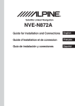
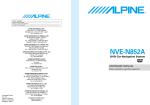
R
R
ALPINE ELECTRONICS, INC.
Tokyo office: 1-1-8 Nishi Gotanda,
Shinagawa-ku, Tokyo 141-8501, Japan
Tel.: (03) 3494-1101
ALPINE ELECTRONICS OF AMERICA, INC.
19145 Gramercy Place, Torrance,
California 90501, U.S.A.
Tel.: 1-800-ALPINE-1 (1-800-257-4631)
1-888-NAV-HELP (1-888-628-4357)
NVE-N852A
DVD Car Navigation System
Guide for Installation and Connections
ALPINE ELECTRONICS OF CANADA, INC.
Suite 203, 7300 Warden Ave. Markham,
Ontario L3R 9Z6, Canada
Tel.: 1-800-ALPINE-1 (1-800-257-4631)
ALPINE ELECTRONICS OF AUSTRALIA PTY. LTD.
6-8 Fiveways Boulevarde Keysborough,
Victoria 3173, Australia
Tel.: (03) 9769-0000
ALPINE ELECTRONICS GmbH
Kreuzerkamp 7-11 40878 Ratingen,
Germany
Tel.: 02102-45 50
ALPINE ITALIA S.p.A.
Via C. Colombo 8, 20090 Trezzano Sul
Naviglio MI, Italy
Tel.: 02-48 47 81
ALPINE ELECTRONICS FRANCE S.A.R.L.
(RCS PONTOISE B 338 101 280)
98, Rue De La Belle Etoile, Z.I. Paris Nord Il
B.P. 50016 F-95945, Roissy,
Charles De Gaulle Cedex, France
Tel.: 01-48 63 89 89
ALPINE ELECTRONICS OF U.K., LTD.
13 Tanners Drive, Blakelands,
Milton Keynes MK14 5BU, U.K.
Tel.: 01908-61 15 56
Yamagata Printing
Co., Ltd.
2-6-34, Takashima,
Nishi-ku, Yokohama,
Kanagawa, Japan
ALPINE ELECTRONICS DE ESPAÑA, S.A.
Portal De Gamarra 36, Pabellón 32
01013 Vitoria (Alava)-Apdo. 133, Spain
Tel.: 34-45-283588
Designed by ALPINE Japan
Printed in Japan (Y)
68P41262Y45-O
Contents
PRECAUTIONS
2
Before Installing the System
4
1. Preparation
7
2. Connections
8
3-1. NVE-N852A Wiring Diagram With CVA-1003 etc.
9
4. Mounting
10
5. Confirmation
12
PRECAUTIONS
■ GUIDE FOR INSTALLATION AND CONNECTIONS
FOR AUTHORIZED ALPINE DEALERS
• Please read this GUIDE FOR INSTALLATION
AND CONNECTIONS FOR AUTHORIZED
ALPINE DEALERS and the OWNER’S MANUAL
thoroughly to familiarize yourself with each control
and function. We at ALPINE hope that your new
NVE-N852A will give you many years of enjoyment.
In case of problems when installing your unit, please
contact your authorized ALPINE dealer.
Points to Observe for Safe Usage
• For safe operation of this system, please read this
manual carefully. We cannot be responsible for
problems resulting from failure to observe the
instructions in this manual.
• Pictorial displays are used to point out safety tips
to prevent harm to yourself or others and property
damage. Here is what these pictorial displays
mean. Knowing them is important to understanding
this manual.
• Meaning of displays
This symbol will precede important
Warning instructions. Failure to heed them
can result in serious injury or death.
This symbol precedes important
instructions. Failure to heed them
Caution can result in injury or property
damages.
Warning
DO NOT DISASSEMBLE OR ALTER.
Doing so may result in an accident, fire or electric
shock.
KEEP SMALL OBJECTS SUCH AS BATTERIES
OUT OF THE REACH OF CHILDREN.
Swallowing them may result in serious injury. If
swallowed, consult a physician immediately.
USE THE CORRECT AMPERE RATING WHEN
REPLACING FUSES.
Failure to do so may result in fire or electric shock.
2
USE ONLY IN CARS WITH A 12 VOLT NEGATIVE
GROUND.
(Check with your dealer if you are not sure.) Failure
to do so may result in fire, etc.
BEFORE WIRING, DISCONNECT THE CABLE
FROM THE NEGATIVE BATTERY TERMINAL.
Failure to do so may result in electric shock or injury
due to electrical shorts.
DO NOT ALLOW CABLES TO BECOME ENTANGLED IN SURROUNDING OBJECTS.
Arrange wiring and cables in compliance with the
manual to prevent obstructions when driving. Cables
or wiring that obstruct or hang up on places such as
the steering wheel, gear lever, brake pedals, etc. can
be extremely hazardous.
DO NOT SPLICE INTO ELECTRICAL CABLES.
Never cut away cable insulation to supply power to
other equipment. Doing so will exceed the current
carrying capacity of the wire and result in fire or
electric shock.
DO NOT INSTALL IN LOCATIONS WHICH MIGHT
HINDER VEHICLE OPERATION, SUCH AS THE
STEERING WHEEL OR GEARSHIFT.
Doing so may obstruct forward vision or hamper
movement etc. and results in serious accident.
DO NOT DAMAGE PIPE OR WIRING WHEN
DRILLING HOLES.
When drilling holes in the chassis for installation, take
precautions so as not to contact, damage or obstruct
pipes, fuel lines, tanks or electrical wiring. Failure to
take such precautions may result in fire.
DO NOT ALTER HARDWARE USED IN ANY
SAFETY-RELATED SYSTEMS DURING INSTALLATION
Never use hardware, utilized to mount critical
components in the steering and brake systems or
fuel tanks, to make wiring or ground connections.
Failure to take such precautions can result in serious
damage from fire or vehicle failure.
DO NOT INSTALL THE MONITOR NEAR THE
PASSENGER SEAT AIR BAG.
If the unit is not installed correctly the air bag may not
function correctly and when triggered the air bag may
cause the monitor to spring upwards causing an
accident and injuries.
MAKE THE CORRECT CONNECTIONS.
Failure to make the proper connections may result in
fire or product damage.
Caution
HAVE THE WIRING AND INSTALLATION DONE
BY EXPERTS.
The wiring and installation of this unit requires
special technical skill and experience. To ensure
safety, always contact the dealer where you purchased this product to have the work done.
USE SPECIFIED ACCESSORY PARTS AND
INSTALL THEM SECURELY.
Be sure to use only the specified accessory parts.
Use of other than designated parts may damage this
unit internally or may not securely install the unit in
place. This may cause parts to become loose
resulting in hazards or product failure.
Precautions
IMPORTANT
Please record the serial number of your unit in the
space provided on the back cover of Owner’s
Manual and keep it as a permanent record. The
serial number plate is located on the bottom of the
unit.
• For installation of the main unit, avoid areas with a
high incidence of dust or moisture. Installing the
unit in such locations may result in contamination
of the DVD ROM making it unreadable.
• Do not install the navigation system near a CD
player that may interfere with GPS signal reception.
• The optimum locations for installing the GPS
antenna are:
– on the dashboard where no metal piece (such as
the defogger wire or antenna wire) is located on
the windshield.
– where no metal cover is located.
• Route the Speed Pulse Sensor cable away from
the audio cables in order to avoid picking up
noises.
DO NOT INSTALL IN LOCATIONS WITH HIGH
MOISTURE OR DUST.
Avoid installing the unit in locations with high incidence of moisture or dust. Moisture or dust that
penetrates into this unit may result in product failure.
ARRANGE THE WIRING SO IT IS NOT CRIMPED
OR PINCHED BY A SHARP METAL EDGE.
Route the cables and wiring away from moving parts
(like the seat rails) or sharp or pointed edges. This
will prevent crimping and damage to the wiring. If
wiring passes through a hole in metal, use a rubber
grommet to prevent the wire’s insulation from being
cut by the metal edge of the hole.
3
Before Installing the System
Mounting the ECU
Wiring
Find a suitable location for the ECU. Avoid any
moving parts, places where moisture can arise,
or locations near extreme heat. Locations such
as under the front seats, or hanging from the
rear package tray work the best.
Caution: The ECU must be mounted horizontal
(less than 5˚). The gyro sensor is mounted
inside the ECU and will not work properly when
the unit is mounted on it’s side. Keep this in
mind when choosing a mounting location.
To wire the NVE-N852A is about as simple as
wiring a cellular phone or a head unit. There are
only seven wires to connect on the main harness. The remaining wire should be used for
connecting to a device having the IN-INT (InInterrupt) function.
Yellow .................. Battery(+)
Black ................... Ground
Red ...................... Ignition(+)
White/Blue ........... Illumination(+)
Green/White ........ Vehicle Speed Sensor (VSS)
Yellow/Blue ......... Parking Brake (+)
Pink/sky blue ....... To a device having the IN-INT
function (–) Negative output
for Audio Mute
Mounting the GPS antenna
The GPS antenna needs to be mounted in a
location that is the most "visible" to the GPS
satellites. Ideally, mounting the antenna on the
top of the roof or on the trunk lid would be the
best location. The GPS antenna typically can
receive the needed signals when mounted
inside of the vehicle, but some precautions
must be taken to insure proper performance.
First, try and mount the system in a location in
the vehicle that allows for the best line-of-site
performance. Locations such as the rear
package tray or front dash work the best.
Secure the antenna with double sided tape or
silicone.
Carefully route the antenna cable and connect it
to the ECU. The cable is matched to its length,
so do not shorten or extend. Avoid making
sharp bends in the cable. Wind excess cable
into large loops.
Cautions: Care should be taken in finding the
proper mounting location. Do not mount under
any metal surface. Some window tinting material, with high metal content like tintanium, can
reduce the GPS antenna’s reception. Also,
some newer vehicles incorporate special heat
resistant glass, Oldsmobile Aurora as an
example, and will cause GPS reception problems. For these types of situations, it is best to
install the GPS on the roof or the rear trunk lid,
use a small amount of silicone or some double
stick tape applied to the bottom of the antenna.
This will prevent the magnetic base from
moving and possibly scratching the paint on the
vehicle.
4
The basic connections for power, ground,
ignition and illumination are very straight forward. The reverse light input is also a necessary connection. It can typically be found at the
transmission switch, the main wire harness that
runs to the taillights or at the reverse light itself.
The navigation unit must know when the vehicle
is driving in reverse, so don’t overlook this
connection. To transmit the state of the parking
brake to the unit, connect the wire to the power
supply side of the parking brake switch.
The most difficult wire to find will be the VSS
wire. This is where the Alpine Application
Support team enters the picture. Simply call 1
(800) TECH-101 and speak with an application
support specialist. We will fax you all of the
necessary information about what color the wire
is and where to find it. For the after hours or
weekend installs, Alpine has a 24 hour Fast Fax
line which can send the information with just a
few key strokes on a touch tone phone. When
calling, please have your dealer account
number and the make, model and year of the
vehicle available. The Alpine Fast Fax phone
number is 1 (800) 978-9655
Caution: Some older vehicles may not have
VSS wires. In this case you must install a speed
pulse generator onto the speedometer cable.
Vehicle Speed Sensor Testing
and Verification
For Digital Type Speed Sensor:
You will need a digital multimeter set to DC
Volts at the 30 volt range or on auto-range. For
front wheel drive, jack up only one of the front
two tires. For rear wheel drive, jack up only one
of the rear wheels. For vehicles with PosiTraction, you will need to jack up both of the
drive line wheels. Be sure to use jack stands
and block the remaining wheels to prevent the
vehicle from rolling. Connect the Black lead of
the multimeter to chassis ground. Probe the
speed pulse wire with the Red lead. Turn the
ignition key to the "ON" or "RUN" position, but
do not start the vehicle. Read the multimeter. It
should show either zero volts (off) or a voltage
ranging from 5-12 volts (on). This voltage range
will differ depending upon the vehicle, however
it will not fluctuate. Rotate the tire slowly. The
voltmeter should change state between zero
volts (off) and 5-12 volts (on) or vice-versa
within 2-3 rotations of the tire. You have now
verified the digital speed pulse.
For Analog Type Speed Sensor
Analog speed pulse is measured as AC voltage, with reference to chassis ground. Due to
varying AC voltages and frequencies, the only
accurate way to verify an analog speed pulse is
to use an oscilloscope. Using a digital
multimeter, verify that the wire does not have a
positive DC voltage by setting it to AC voltage
at the 30 volt range or on auto-range. Connect
the black lead of the multimeter to chassis
ground. Probe the speed pulse wire with the red
lead. The meter should read zero volts. Start
the car and begin to drive slowly. It is a good
idea to have someone with you in the vehicle to
read the multimeter while you keep your eyes
on the road. The meter should slowly begin to
show an increase AC voltage will increase as
well. Maximum AC voltage should be somewhere around 5-8 volts at 60 MPH.
NOTE: Please do not confuse this process with
checking the tachometer wire. The tach wire
increases voltage with the engine's RPM. The
speed pulse wire increases voltage with the
vehicle's actual speed. If any of these conditions differ with your findings, please call
Application Support at (800) TECH-101.
Resources For VSS Information
Alpine constantly performs research on a
variety of vehicles and is currently compiling a
database of VSS wire information. This information is available to you 24 hours a day on our
Fast Fax line at 1 (800)978-9655. Please have
your dealer account number ready when
calling. If calling for first time and you do not
know the document number you are requesting,
please order document number 02 (Dealer
Master Index).
If you happen to come across a vehicle that is
not listed in the database, please call Alpine
Application Support at (800) TECH-101.
Testing The System
To allow the ECU to sync up with the GPS
satellites you must park the vehicle outside in
an open area. The GPS antenna has the best
reception, away from tall buildings or trees. This
process will take the system about 10 to 30
minutes to receive the GPS data and find the
approximate vehicle location. Turn on the unit.
Once the unit "wakes up" and the disclaimer
screen appears, press the "ENTER" button.
The map screen should appear. The vehicle
icon may appear on a blank map screen (no
roads are illustrated). This condition is normal.
Also note the GPS signal icon located on the
upper left hand corner of the screen. It is in the
shape of a satellite, and will initially appear dark
grey with a black background. Once the unit
receives the GPS data, the GPS icon change
color from dark grey (no reception), to light blue
(minimum reception), and finally yellow (maximum reception). The vehicle icon should now
be placed onto the map with your approximate
vehicle location. Don't worry if your map position is a block or so away from your actual
position, the system will correct itself as you
drive. If the GPS icon does not change color in
the specified time period, move the vehicle to
another location or relocate the antenna and try
again.
5
The Test Drive
The navigation system must be driven for about
10 to 15 minutes on actual roads for the map
matching process to accurately place the
vehicle in the correct position. Don’t worry if the
system has you driving in the wrong direction
on the map. Also note that the grey bar on the
bottom of the screen should display the current
street name within this time period. The more
you drive, the more the system will correct
itself. If the vehicle icon does not move
smoothly as you drive, or the street name does
not appear on the bottom of the screen, you
may not have the proper VSS wire. Double
check your connections and verify the VSS wire
once again.
Self Calibration
It is normal that the system may not exactly
follow the vehicle's path for about a day or so.
The system is learning the vehicle. It is calibrating the speed pulse and gyro and checking it
with the GPS. The more the vehicle is driven,
the more accurate the system becomes. This is
also true if the tire size is changed. The system
may be a little off for a day or so but it will
correct itself.
System Check
With the system on, please confirm the following
items for proper operation:
GPS reception: The GPS icon will be colored
blue when the system receives 3 satellites and
yellow when 4 or more satellites are received.
Illumination: When the parking lights are on the
screen should dim (the brightness can be
controlled through the setup mode).
Reverse: The vehicle will back up on the map
when the vehicle is in reverse and moving
backwards.
Speed pulse (VSS): Just drive, if the VSS is
correct, the vehicle will move with you and stop
when you stop.
6
What if the vehicle doesn't have a
VSS wire ?
Most pre-1980 vehicle have mechanical speedometers and do not employ cruise control
systems. Therefore, these vehicles may not
have a VSS wire. Alpine speed pulse generator
NVE-K300 is separately sold. This will magnetize the metal in the tire of the vehicle. The
magnetic field created is sensed as a pulse
during for each rotation of the tire. The number
of tire rotations is used to calculate the vehicle’s
speed. Not all vehicles can use this generator,
but it can be a solution for most of these vehicles.
1. Preparation
1
Check accessory parts.
(5 m)
GPS antenna
Antenna
mounting plate
×3
Cable clamp
×2
Parking brake
aux. cord
Solderless
connector
Remote
Control
Remote Control
Holder
×2
(2.5 m)
Power cable (4.5 m) 13P RGB extension cable (6 m)
1 Bracket
2 Floor base
×4
2
7 Flanged Hex
Nut (M6)
8 Wing Nut (M6)
×4
4 Hex bolt (M6 × 50)
×4
×2
One each left and right
6 Spring
washer (M6)
3 Screw with double
washer (M5 × 8)
Battery (AAA)
×4
9 Velcro
Fastener
×4
! Velcro Tape
×2
5 Flanged self-tapping
screw (M5 × 15)
×4
" Self-tapping
Screw (M3 × 12)
×4
Prepare tools and mounting information.
Screwdriver
Electrical tape
Pliers
3
Park the vehicle in a safe and level location.
4
Apply the brake and remove the ignition key.
5
Mount the antenna on the roof.
Spanner
Clean dust and oil at the mounting location and mount the antenna.
Notes:
• The magnet of the antenna is very strong. Proceed cautiously to prevent any
damage to the vehicle’s body. Keep the magnet away from articles susceptible
to magnetic fields such as credit cards, watches, etc.
• Do not paint the antenna. Reception sensitivity may be decreased.
Pencil and eraser
Antenna
Mounting the antenna inside the vehicle.
1. Clean the mounting location.
2. Put on the antenna mounting plate.
3. Mount the antenna.
Notes:
• Mount the antenna on a flat plane of the dash board or rear tray.
• Some thermal reflection type or thermal absorption type glass may interrupt
high frequency waves. If reception is poor with the antenna installed inside the
car, try to mount the antenna outside the car.
Antenna
7
6
Routing the antenna cable.
1. Route the cable using the provided cable clamps to take up
the cable’s slack.
2. Use the waterproof pad when running the cable under the
vehicle’s rubber gasket.
3. Attach the cable at several points using the remaining cable
clamps.
Water
proof pad
Cable
clamps
2. Connections
1
Disconnect the battery (–) terminal.
2
Connect the power lead to this unit.
3
Wrap electrical tape around end of leads not used.
4
Connect the battery (–) terminal and turn the ignition key to the ACC or ON position. Check to see if operation can be performed properly.
Note:
Some vehicles contain a vehicle control computer etc. in this case, contents of
the computer memory may be erased when the battery (–) lead is disconnected.
Insert until a click sound is heard.
(Is the power turned on? Is the illumination turned on?)
You can check the language selection menu with the monitor. (Refer to the Owner’s Manual for details.)
ON
8
3. NVE-N852A Wiring Diagram With CVA-1003 etc.
∗ The connecting with CVA-1005/CVA-1006/IVA-C800/IVA-C801/TME-M750/
TME-M750A/TME-M790 are also the same as this diagram.
Battery Lead (Yellow)
(5A)
BATTERY
Ignition (Red)
To the Acc power lead
(5A)
Ground (Black)
Connect to a metal
part of chassis
body with screw
Illumination (Dimmer) (+) (White/Blue)
To the Illumination
signal line
Parking Brake (Yellow/Blue)
To the parking brake
signal line
CVA-1003
Speed Sensor (Green/White)
Connect to VSS (Digital or Analog 0V – 3V)
*
To the vehicle speed
pulse line
Mute (Pink/Sky blue)
Use this to connect
a device having the
IN-INT function (–)
output for Audio Mute
GPS Antenna (Included)
Note: SOLDER ALL
CONNECTIONS
A
1 2 3 4 5
6 7 8 9 10
Power Connector Pin
Configuration
13P RGB Extension Cable Included
1
2
Ground (Black)
Acc (Ignition) (Red)
3
4
5
Mute (Pink/Sky blue)
Open
Open
6
7
Battery (Yellow)
Dimmer In (Illumination) (White/Blue)
8
Speed Sensor (Green/White)
9 Parking Brake (Yellow/Blue)
10 Open
A
MIC/SW
TO DISP.
EX-1
POWER
EX-2
GPS ANT.
Use for future system expansion
5
1
10
6
* Improper connection of the
speed pulse line may cause
important safety features of
the vehicle to fail (such as
the brakes or air bag). Such
failures may result in an
accident and loss of life. We
strongly recommend that the
installation be performed by
a trained, authorized Alpine
dealer.
9
4. Mounting
Note:
The main unit must be mounted within ±5 degrees of the
horizontal, left to right, and 30 degrees of the horizontal, back
to front.
Less than 30°
a When mounting using Velcro fastener
1
Place Velcro fastener.
2
Press the Navigation unit onto the
Velcro fastener at the mounting position.
Place two pieces of Velcro fastener onto the mounting surface. The rough side should be facing the navigation
unit.
Remove the backing to the adhesive on the Velcro
strips. Press the Navigation unit onto the mounting
location.
Floor
Continued to 5. Securing leads, etc.
Velcro fastener
a When mounting on the rear tray
1
Mount the brackets 1 on the unit.
Mount the brackets at both sides of the unit with
screws with double washer (M5×8) 3.
Depending on the locations of the
mounting screw holes, the mounting
brackets (for the left and right) can be
used on either side.
2
1
3
(Bottom side)
3
Attach the unit on the rear tray.
4
Attach the unit securely with hex bolts (M6×50) 4,
flanged hex nut (M6) 7, spring washers (M6) 6,
and wing nuts (M6) 8.
Continued to 5. Securing leads, etc.
7
(Bottom
side)
6
8
10
a When mounting the unit directly on the floor
1
Mount the brackets 1 on the unit.
Mount the brackets at both sides of the unit with
screws with double washer (M5×8) 3.
3
1
2
Depending on the locations
of the mounting screw holes,
the mounting brackets (for
the left and right) can be
used on either side.
3
Mount the unit on the floor.
Mount the unit on the floor with flanged self-tapping
screws (M5×15) 5 and spring washers (M6) 6.
5
6
Warning: Do not damage pipe or wiring when
drilling holes.
Continued to 5 . Securing leads. etc.
a When mounting with floor base brackets
1
Mount the brackets 1.
Mount the brackets 1 at both sides of the unit with
screws with double washer (M5×8) 3.
3
1
2
Determine mounting position of the
floor base 2 for placement under the
carpet.
Depending on the locations
of the mounting screw holes,
the mounting brackets (for
the left and right) can be
used on either side.
3
8
6
2
11
3
Cut the carpet in "x" shape with a
cutter and insert the floor base 2
from under side of the carpet.
4
Mount the unit on the carpet with
spring washer (M6) 6 and wing nuts
(M6) 8.
2
8
6
Continued to 5. Securing leads, etc.
5
Securing leads, etc.
6
Connect the battery (–) terminal.
Make sure leads are not pinched by moving parts such as the seat rail, etc. Also check for damaged from
sharp edges or protrusions.
5. Confirmation
1
Turn on the engine key. Make sure
the unit is operating correctly by
referring to the Owner’s Manual.
2
Make sure all factory components
such as brake lamps, parking lamps,
etc. work correctly.
a Remote control holder mounting method
• If the remote control is in direct sunlight, remove it
from the holder and keep it in the glove box.
• When the holder cannot be mounted securely with
double-sided adhesive tape !, mount it by using
screws ".
ON
Reinforcement screws "
Remote
control
Remote control
holder
Protective Paper
!*
Console box, etc.
* Double-sided adhesive tape (Before putting on the
holder, clean dirt on the mounting location)
12
13
14
15