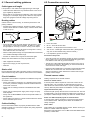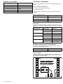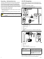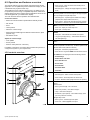
1
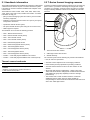
T-S e r ie s
Ins ta lla tion a nd ope ra tion
ins tructions
En g lis h
Da te : 08-2012
Docume nt numbe r: 81338-3-EN
© 2012 Ra yma rine UK Limite d
Trademarks and patents notice
Autohelm, hsb2, RayTech Navigator, Sail Pilot, SeaTalk, SeaTalkNG, SeaTalkHS and Sportpilot are registered trademarks of Raymarine
UK Limited. RayTalk, Seahawk, Smartpilot, Pathfinder and Raymarine are registered trademarks of Raymarine Holdings Limited.
FLIR is a registered trademark of FLIR Systems, Inc. and/or its subsidiaries.
All other trademarks, trade names, or company names referenced herein are used for identification only and are the property of
their respective owners.
This product is covered by one or more of US Patent Nos: 7470904; 7034301; 6812465; 7470902; 6929410 and other patents
pending, or design patents pending.
Fair Use Statement
You may print no more than three copies of this manual for your own use. You may not make any further copies or distribute or use the
manual in any other way including without limitation exploiting the manual commercially or giving or selling copies to third parties.
Export control
T303, T403, T453, T463, T470SC and T473SC thermal cameras are controlled by US export laws.
There are special versions of the system that are approved for international distribution and travel. Please contact Raymarine customer
support if you have any questions.
Contact details can be found on the Raymarine website, www.raymarine.com.
Export Administration Regulations (EAR)
This document is controlled to Raymarine Technology Level 1. The information contained in this document pertains to a dual use
product controlled for export by the Export Administration Regulations (EAR). Raymarine trade secrets contained herein are subject to
disclosure restrictions as a matter of law. Diversion contrary to US law is prohibited. US Department of Commerce authorization is not
required prior to export or transfer to foreign persons or parties unless otherwise prohibited.
Software updates
Check the website www.raymarine.com for the latest software releases for your product.
Product handbooks
The latest versions of all English and translated handbooks are available to download in PDF format from the website www.raymarine.com.
Please check the website to ensure you have the latest handbooks.
Copyright ©2012 Raymarine UK Ltd. All rights reserved.
ENGLISH
Document number: 81338-3
Date: 08-2012
Contents
Chapter 1 Important information............................. 7
Cleaning the thermal camera........................................... 7
Water ingress ................................................................. 7
Disclaimers .................................................................... 7
EMC installation guidelines ............................................. 8
Suppression ferrites ........................................................ 8
Connections to other equipment ...................................... 8
Declaration of conformity................................................. 8
Product disposal ............................................................. 8
Warranty registration....................................................... 8
IMO and SOLAS............................................................. 8
Technical accuracy ......................................................... 8
Chapter 2 Handbook information............................ 9
2.1 Handbook information ............................................... 10
2.2 T-Series thermal imaging cameras ............................. 10
Chapter 3 Planning the installation ........................ 11
3.1 Thermal camera system ............................................ 12
3.2 Installation checklist .................................................. 13
3.3 Typical systems with thermal cameras........................ 14
3.4 Thermal camera parts supplied .................................. 16
3.5 JCU — Parts supplied ............................................... 16
3.6 Tools required ........................................................... 17
Chapter 4 Cables and connections......................... 19
4.1 General cabling guidance .......................................... 20
4.2 Connection overview ................................................. 20
4.3 Power connection ..................................................... 21
4.4 JCU Connection........................................................ 22
Chapter 5 Installation ............................................... 25
5.1 Camera mounting ..................................................... 26
5.2 JCU Mounting........................................................... 27
Chapter 6 System operation and setup.................. 29
6.1 Thermal camera image.............................................. 30
6.2 Operation and features overview................................ 31
6.3 Power up and standby............................................... 32
6.4 Camera control ......................................................... 32
6.5 Image adjustments.................................................... 33
6.6 System reset ............................................................ 34
6.7 Setup menus ............................................................ 35
Chapter 7 Troubleshooting and support ................ 37
7.1 Thermal camera troubleshooting ................................ 38
7.2 Raymarine customer support ..................................... 39
Chapter 8 Technical specification........................... 41
8.1 Technical specification............................................... 42
5
6
T-Series
Chapter 1: Important information
Warning: Product installation and
operation
This product must be installed and operated in
accordance with the instructions provided. Failure to
do so could result in personal injury, damage to your
vessel and/or poor product performance.
Warning: Potential ignition source
This product is NOT approved for use in
hazardous/flammable atmospheres. Do NOT install in
a hazardous/flammable atmosphere (such as in an
engine room or near fuel tanks).
Warning: Product grounding
Before applying power to this product, ensure it has
been correctly grounded, in accordance with the
instructions in this guide.
Warning: Switch off power supply
Ensure the vessel’s power supply is switched OFF
before starting to install this product. Do NOT connect
or disconnect equipment with the power switched on,
unless instructed in this document.
Warning: Entrapment hazard
This product features moving parts that provide a
potential entrapment hazard. Keep clear of moving
parts at all times.
Warning: Ensure safe navigation
This product is intended only as an aid to navigation
and must never be used in preference to sound
navigational judgment. Only official government
charts and notices to mariners contain all the current
information needed for safe navigation, and the
captain is responsible for their prudent use. It is the
user’s responsibility to use official government charts,
notices to mariners, caution and proper navigational
skill when operating this or any other Raymarine
product.
Warning: Maintain a permanent watch
Always maintain a permanent watch, this will allow
you to respond to situations as they develop. Failure
to maintain a permanent watch puts yourself, your
vessel and others at serious risk of harm.
Caution: Service and maintenance
This product contains no user serviceable
components. Please refer all maintenance and repair
to authorized Raymarine dealers. Unauthorized repair
may affect your warranty.
Caution: Sun covers
• To protect your product against the damaging
effects of ultraviolet (UV) light, always fit the sun
covers when the product is not in use.
• Remove the sun covers when travelling at high
speed, whether in water or when the vessel is being
towed.
Cleaning the thermal camera
The camera housing and lens will require occasional cleaning.
Raymarine suggests that you clean the lens when image quality
degradation is noticed or excessive contaminant buildup is seen.
Clean the interface between the yoke and base often to prevent
accumulation of debris or salt deposits.
When cleaning this product:
• Do NOT wipe the lens window with a dry cloth, as this could
scratch the coating.
• Do NOT use abrasive, or acid or ammonia based products.
• Do NOT pressure wash.
Particular care should be taken when cleaning the lens window, this
has a protective anti-reflective coating which may be damaged by
improper cleaning.
1. Switch off the power to the unit.
2. Clean the camera body with a clean, soft cotton cloth. You can
moisten the cloth and use a mild detergent if required.
3. Clean the camera lens.
• Rinse the lens with fresh water to remove all dirt particles and
salt deposits, and allow to dry naturally.
• If any spots or smears remain, very gently wipe the lens
window with a clean microfibre cloth or soft cotton cloth.
• If necessary, use isopropyl alcohol (IPA) or a mild detergent to
remove any remaining spots or marks.
Water ingress
Water ingress disclaimer
Although the waterproof rating capacity of this product meets the
IPX6 standard, water intrusion and subsequent equipment failure
may occur if the product is subjected to commercial high-pressure
washing. Raymarine will not warrant products subjected to
high-pressure washing.
Caution: Do not open the unit
The unit is factory sealed to protect against
atmospheric humidity, suspended particulates and
other contaminates. It is important that you do not
open the unit or remove the casing for any reason.
Opening the unit will:
• compromise the seal with possible damage to the
unit, and
• void the manufacturer’s warranty.
Caution: Power supply protection
When installing this product ensure the power source
is adequately protected by means of a suitably-rated
fuse or automatic circuit breaker.
Important information
Disclaimers
This product (including the electronic charts) is intended to be used
only as an aid to navigation. It is designed to facilitate use of official
government charts, not replace them. Only official government
charts and notices to mariners contain all the current information
needed for safe navigation, and the captain is responsible for their
prudent use. It is the user’s responsibility to use official government
charts, notices to mariners, caution and proper navigational skill
when operating this or any other Raymarine product. This product
supports electronic charts provided by third party data suppliers
which may be embedded or stored on memory card. Use of such
charts is subject to the supplier’s End-User Licence Agreement
included in the documentation for this product or supplied with the
memory card (as applicable).
Raymarine does not warrant that this product is error-free or that it
is compatible with products manufactured by any person or entity
other than Raymarine.
7
This product uses digital chart data, and electronic information from
the Global Positioning System (GPS) which may contain errors.
Raymarine does not warrant the accuracy of such information and
you are advised that errors in such information may cause the
product to malfunction. Raymarine is not responsible for damages
or injuries caused by your use or inability to use the product, by the
interaction of the product with products manufactured by others, or
by errors in chart data or information utilized by the product and
supplied by third parties.
Product disposal
Dispose of this product in accordance with the WEEE Directive.
The Waste Electrical and Electronic Equipment (WEEE)
Directive requires the recycling of waste electrical and electronic
equipment. Whilst the WEEE Directive does not apply to some
Raymarine products, we support its policy and ask you to be aware
of how to dispose of this product.
EMC installation guidelines
Raymarine equipment and accessories conform to the appropriate
Electromagnetic Compatibility (EMC) regulations, to minimize
electromagnetic interference between equipment and minimize the
effect such interference could have on the performance of your
system
Correct installation is required to ensure that EMC performance is
not compromised.
For optimum EMC performance we recommend that wherever
possible:
Warranty registration
To register your Raymarine product ownership, please visit
www.raymarine.com and register online.
It is important that you register your product to receive full warranty
benefits. Your unit package includes a bar code label indicating the
serial number of the unit. You will need this serial number when
registering your product online. You should retain the label for future
reference.
• Raymarine equipment and cables connected to it are:
– At least 1 m (3 ft) from any equipment transmitting or cables
carrying radio signals e.g. VHF radios, cables and antennas.
In the case of SSB radios, the distance should be increased
to 7 ft (2 m).
– More than 2 m (7 ft) from the path of a radar beam. A radar
beam can normally be assumed to spread 20 degrees above
and below the radiating element.
• The product is supplied from a separate battery from that used
for engine start. This is important to prevent erratic behavior
and data loss which can occur if the engine start does not have
a separate battery.
• Raymarine specified cables are used.
• Cables are not cut or extended, unless doing so is detailed in
the installation manual.
Note: Where constraints on the installation prevent any of
the above recommendations, always ensure the maximum
possible separation between different items of electrical
equipment, to provide the best conditions for EMC performance
throughout the installation
IMO and SOLAS
The equipment described within this document is intended for use
on leisure marine boats and workboats not covered by International
Maritime Organization (IMO) and Safety of Life at Sea (SOLAS)
Carriage Regulations.
Technical accuracy
To the best of our knowledge, the information in this document
was correct at the time it was produced. However, Raymarine
cannot accept liability for any inaccuracies or omissions it may
contain. In addition, our policy of continuous product improvement
may change specifications without notice. As a result, Raymarine
cannot accept liability for any differences between the product
and this document. Please check the Raymarine website
(www.raymarine.com) to ensure you have the most up-to-date
version(s) of the documentation for your product.
Suppression ferrites
Raymarine cables may be fitted with suppression ferrites. These
are important for correct EMC performance. If a ferrite has to be
removed for any purpose (e.g. installation or maintenance), it must
be replaced in the original position before the product is used.
Use only ferrites of the correct type, supplied by Raymarine
authorized dealers.
Connections to other equipment
Requirement for ferrites on non-Raymarine cables
If your Raymarine equipment is to be connected to other equipment
using a cable not supplied by Raymarine, a suppression ferrite
MUST always be attached to the cable near the Raymarine unit.
Declaration of conformity
Raymarine UK Ltd. declares that this product is compliant with the
essential requirements of EMC directive 2004/108/EC.
The original Declaration of Conformity certificate may be viewed on
the relevant product page at www.raymarine.com.
8
T-Series
Chapter 2: Handbook information
Chapter contents
•
2.1 Handbook information on page 10
•
2.2 T-Series thermal imaging cameras on page 10
Handbook information
9
2.1 Handbook information
2.2 T-Series thermal imaging cameras
This handbook describes the installation and operation of Raymarine
T-Series thermal cameras as part of a marine electronics system.
It provides an overview of features available and examples of the
controls used.
T-Series is a maritime thermal imaging system for use on nearly any
kind of vessel. It provides a clear image in low-light and no-light
conditions. For example, a thermal camera can help you navigate
at night or identify obstacles in areas of low visibility or even total
darkness.
This handbook covers models: T300, T303, T350, T353, T400,
T403, T450, T453, T460, T463, T470SC and T473SC. It includes
information to help you:
• plan your thermal imaging system and ensure you have all the
necessary equipment,
• install and connect the thermal camera as a part of your system
of Raymarine electronics,
1
• operate the thermal camera system,
• set up the thermal camera system using the on-screen menus,
2
• obtain support if required.
The handbook is for use with the following products:
3
• T300 – QVGA Thermal camera
• T303 – QVGA Thermal camera (30 Hz)
• T350 – VGA Thermal camera
• T353 – VGA Thermal camera (30 Hz)
• T400 – QVGA dual payload camera
• T403 – QVGA dual payload camera (30 Hz)
• T450 – VGA dual payload camera
D11974-2
• T453 – VGA dual payload camera (30 Hz)
• T460 – VGA dual payload camera
1. Thermal camera lens window
• T463 – VGA dual payload camera (30 Hz)
2. Visible light camera lens window
• T470SC — VGA dual payload stabilized color camera
3. Gimbal assembly
• T473SC — VGA dual payload stabilized color camera (30 Hz)
The T-Series system has the following key functions and features:
• Pan, tilt and zoom operations.
Thermal camera handbooks
• Automatic camera adjustment to suit changing conditions.
Description
Part number
• Preset modes (Scenes) optimized for prevailing conditions.
T-Series thermal cameras installation and operation
handbook
Installation, commissioning and operation instructions for
T-Series thermal camera systems.
81338
• Automatic window heaters to de-ice the lens window in cold
weather.
• Single and dual payload configurations. (T400, T403, T450,
T453, T460 and T463 are dual payload models with both thermal
and visible light (greyscale) capability to enhance low light
performance.)
• The T470SC and T473SC models includes a mechanical
stabilization feature which improves image stability by
compensating for vessel motion and both thermal and continuous
zoom color visible light camera.
10
T-Series
Chapter 3: Planning the installation
Chapter contents
•
3.1 Thermal camera system on page 12
•
3.2 Installation checklist on page 13
•
3.3 Typical systems with thermal cameras on page 14
•
3.4 Thermal camera parts supplied on page 16
•
3.5 JCU — Parts supplied on page 16
•
3.6 Tools required on page 17
Planning the installation
11
3.1 Thermal camera system
A typical thermal camera system comprises the items shown below:
Multifunction display
system
Direct video
C-Series Widescreen
— C90W, C120W,
C140W
●
E-Series Classic —
E80, E120
●
Network video
Integrated
camera
controls
Note: Displays without integrated camera controls require a
separate JCU (Joystick Control Unit).
1
Dedicated camera controllers
Controller
Description
Joystick control
unit (JCU)
Dedicated thermal camera controller, featuring 3 axis puck
control, function keys and an LCD display.
3
2
D11966-2
1. Thermal camera
2. Controller – This provides the controls to operate and configure
the camera.
3. Display – This displays the thermal video image as well
as status information and on-screen menus provided by the
camera.
Note: The controller and display may be the same device. Some
Raymarine multifunction displays provide a thermal camera
application which has a set of integral camera controls.
Additional controllers and equipment
You may have additional equipment as part of your thermal camera
system:
• Multiple controllers and displays, for example a camera serving
multiple display / control stations.
• SeaTalkhs network switch – Used to create a network of
compatible Raymarine equipment.
• GVM video module – Used to distribute the video signal around a
Raymarine G-Series system.
Compatible displays and controllers
The following Raymarine displays and systems are compatible with
the T-Series range of thermal cameras.
Multifunction display
system
Direct video
Network video
Integrated
camera
controls
c-series — c95, c97,
c125 , c127
●
●
e-series — e7, e7D,
e95, e97, e125, e127
●
●
G-Series system
● (direct
to G-Series
monitor)
E-Series Widescreen
— E90W, E120W,
E140W
●
12
● (using
GVM400 video
module)
●
●
T-Series
3.2 Installation checklist
Installation includes the following activities:
Installation Task
1
Plan your system.
2
Obtain all required equipment and tools.
3
Site all equipment.
4
Route all cables.
5
Drill cable and mounting holes.
6
Make all connections into equipment.
7
Secure all equipment in place.
8
Power on and test the system.
Schematic diagram
A schematic diagram is an essential part of planning any installation.
It is also useful for any future additions or maintenance of the
system. The diagram should include:
• Location of all components.
• Connectors, cable types, routes and lengths.
Planning the installation
13
.
147IBAKJ2580CLVDM
369FEONYXZPMW
T
S
G
H
U
O
R
Q
3.3 Typical systems with thermal cameras
Example system with fully integrated display
2
1
3
4
5
6
D11964-2
SeaTalkhs – Includes the camera control communications.
Video cable – Carries the thermal / visible light video image.
1
e/c-series display
4
PoE injector (Required if JCU is included in the system.)
2
Thermal camera
5
JCU (optional)
3
Raymarine network switch
6
SeaTalkhs to other digital devices: Additional displays / controllers, Radar,
etc.
G-Series system
1
2
1
2
ABC
4
GHI
ENTER
5
JKL
3
3
DEF
6
MNO
WPTS
PAGE
MENU
MOB
OUT
RANGE
7
8
9
PQRS
TUV
WXYZ
.
0
IN
ACTIVE
DODGE
DATA
STANDBY
PILOT
OK
CANCEL
6
5
4
8
9
7
D11965-2
Video cable
SeaTalkhs – Includes the camera control communications (and video
signal on G-Series system).
1
G-Series Nav station
6
G-Series GVM400 video module
2
Repeat monitor
7
Thermal camera
3
G-Series GPM400
8
JCU (optional)
4
Raymarine network switch
9
PoE injector (Required if JCU is included in the system.)
5
Glass bridge monitor
14
T-Series
System with basic / classic display(s)
This arrangement is applicable for displays which do not have the thermal camera application and integrated camera controls.
3
1
2
D11978-2
Video cable – Carries the thermal / visible light video image.
Ethernet – Includes the camera control
1
Thermal camera
2
JCU (required)
3
Monitor / Display
SeaTalkhs
SeaTalkhs is an ethernet based marine network. This high speed
protocol allows compatible equipment to communicate rapidly and
share large amounts of data.
Information shared using the SeaTalkhs network includes:
• Shared cartography (between compatible displays).
• Digital radar data.
• Sonar data.
Planning the installation
15
3.4 Thermal camera parts supplied
3.5 JCU — Parts supplied
T-Series thermal cameras with JCU included are supplied with the
following additional parts:
x6
x6
2
x6
1
x6
2
3
D11991-1
4
6
141.4 mm (5.6 in) outside of JCU
3
129.54 ±1.25 mm (5.1 ±0.049 in) cutout
1
This document may not print true to scale. Before modifying mounting
surface, ensure printed template matches the measurements provided.
5
123.2 mm (4.9 in) optional drill guide
72.4 mm (2.9 in) optional drill guide
4
D11968-2
78.74 ±1.25 mm (3.1 ±0.049 in) cutout
1. T-Series thermal camera
90.4 mm (3.6 in) outside of JCU
6.4 mm
(0.25 in)
diameter
2. Mounting fasteners
3. Ethernet waterproof coupler
4. Small O-ring
5
6
5. Documentation pack (containing: camera mounting template,
warranty policy and documentation CD.)
6. Large O-ring
Unpack the camera unit carefully to prevent damage. Save the
carton and packing in case the unit has to be returned for service.
Additional items required
To complete the installation you will also need to obtain the following
items:
D11967-2
1. Joystick Control Unit (JCU).
2. Bezel.
3. Sun cover.
4. Mounting template
• Compatible display / control hardware.
5. Power over Ethernet (PoE) injector.
• Cables for power, ground, video and network connection.
6. PoE cable 7.62m (25').
• Thread locking compound (for example Loctite 242 or equivalent),
required for all metal-to-metal threaded connections.
Note: The JCU part number E32130 can also be ordered
separately.
Optional accessories
You may also require the following items:
• Top Down Installation Kit (plate or riser). Required if the camera
is to be mounted on a surface with no access to the underside (for
example on top of a sealed enclosure).
16
T-Series
3.6 Tools required
The following tools are required for installation.
1
2
3
5
4
6
D12333-1
Item
Description
1.
Drill
2.
6mm spanner
3.
6.4mm drill bit
4.
Jigsaw (only required for JCU
installation)
5.
Pozi-drive screwdriver (only required
for JCU installation)
6.
Thread-lock
Planning the installation
17
18
T-Series
Chapter 4: Cables and connections
Chapter contents
•
4.1 General cabling guidance on page 20
•
4.2 Connection overview on page 20
•
4.3 Power connection on page 21
•
4.4 JCU Connection on page 22
Cables and connections
19
4.1 General cabling guidance
4.2 Connection overview
Cable types and length
It is important to use cables of the appropriate type and length
• Unless otherwise stated use only standard cables of the correct
type, supplied by Raymarine.
• Ensure that any non-Raymarine cables are of the correct quality
and gauge. For example, longer power cable runs may require
larger wire gauges to minimize voltage drop along the run.
Routing cables
Cables must be routed correctly, to maximize performance and
prolong cable life.
5
• Do NOT bend cables excessively. Wherever possible, ensure a
minimum bend diameter of 200 mm (8 in) / minimum bend radius
of 100 mm (4 in).
200 mm (8 in)
1
2
3
4
100 mm (4 in)
D11957-1
• Protect all cables from physical damage and exposure to heat.
Use trunking or conduit where possible. Do NOT run cables
through bilges or doorways, or close to moving or hot objects.
• Secure cables in place using tie-wraps or lacing twine. Coil any
extra cable and tie it out of the way.
• Where a cable passes through an exposed bulkhead or deckhead,
use a suitable watertight feed-through.
• Do NOT run cables near to engines or fluorescent lights.
Always route data cables as far away as possible from:
• other equipment and cables,
• high current carrying ac and dc power lines,
• antennae.
1. Power and drain
2. IR out – Thermal camera video
3. SeaTalkhs – To Raymarine network switch or JCU
4. VIS / IR out – Visible light and thermal video. (Dual payload
only, VIS / IR are switched using camera controls.)
5. Low impedance ground connection
Connection care points:
• You must provide a low impedance chassis to ground connection,
this is made to any one of the chassis threaded fixing points and
is in addition to the drain-to-ground connection.
• The 450 mm (18in) cable tails should be routed to a dry area of
the vessel for connection. Alternatively you must ensure that all
connections are made water tight.
Ensure adequate strain relief is provided. Protect connectors from
strain and ensure they will not pull out under extreme sea conditions.
• Ensure that the VIS/IR feed is connected on dual payload models.
Without this connection the user will not be able to use the
camera controllers to switch between the thermal and low light
(visible) camera images.
Circuit isolation
Thermal camera cables
Appropriate circuit isolation is required for installations using both
AC and DC current:
Cabling requirements for thermal cameras.
Strain relief
• Always use isolating transformers or a separate power-inverter
to run PC’s, processors, displays and other sensitive electronic
instruments or devices.
• Always use an isolating transformer with Weather FAX audio
cables.
• Always use an isolated power supply when using a 3rd party
audio amplifier.
• Always use an RS232/NMEA converter with optical isolation on
the signal lines.
• Always make sure that PC’s or other sensitive electronic devices
have a dedicated power circuit.
Cable shielding
Ensure that all data cables are properly shielded that the cable
shielding is intact (e.g. hasn’t been scraped off by being squeezed
through a tight area).
Camera to network switch
A network patch cable is required to connect the camera to the
network switch. The connection is made between the camera
cable tail and the network switch via the coupler (supplied with the
camera). Network patch cables are available in a variety of lengths.
Joystick Control Unit (JCU)
An Ethernet (with power) cable is used to connect the JCU. The JCU
is supplied with a 7.62 m (25 ft) Ethernet cable for this connection. If
you require a different length contact your dealer for suitable cables.
Power over Ethernet (PoE) injector to network switch
A network patch cable is required for connecting the PoE injector
to the network switch. Network patch cables are available in a
variety of lengths.
Video cables
Video cables are not supplied with the product. Please contact your
dealer for suitable cables and adaptors.
Raymarine recommends the use of a BNC terminated RG59 75ohm
(or better) coaxial cable.
20
T-Series
4.3 Power connection
SeaTalkhs patch cables
Cable
Part number
1.5 m (4.9 ft) SeaTalkhs patch cable
E06054
Power must be supplied to the camera from an appropriate power
source.
5 m (16.4 ft) SeaTalkhs patch cable
E06055
Power connection requirements
10 m (32.8 ft) SeaTalkhs patch cable
E06056
• 12 or 24 Vdc nominal supply voltage
15 m (49.2 ft) SeaTalkhs patch cable
A62136
• Isolated power supply
20 m (65.6 ft) SeaTalkhs patch cable
E06057
• Connected via an appropriately rated thermal breaker or fused
switch.
Power connection colors
Color
Description
Red
Power in +ve (12 / 24 V)
Black
Power in -ve (0 V)
Green
Drain / Ground
Power cable
The power connection is made to a 450 mm (18 in) tail out of the
camera base. Extend this tail with appropriate cable as per the table
below.
Total length (max)
Supply voltage
Cable size
0–8 m (25 ft)
12 V
1.5 mm2 (16 AWG)
24 V
0.8 mm2 (18 AWG)
12 V
2.0 mm2 (14 AWG)
24 V
0.8 mm2 (18 AWG)
12 V
3.5 mm2 (12 AWG)
24 V
0.8 mm2 (18 AWG)
12 V
5.5 mm2 (10 AWG)
24 V
0.8 mm2 (18 AWG)
8–16 m (50 ft)
16–24 m (75 ft)
24–32 m (100 ft)
Breakers, fuses and circuit protection
Raymarine recommends that you fit a thermal breaker or fuse for
the camera at the distribution panel.
Camera
Recommended fuse
All models
5 Amp.
Sharing a breaker
Where more than 1 piece of equipment shares a breaker you must
provide protection for the individual circuits. E.g. by connecting an
in-line fuse for each power circuit.
+VE bar
-VE bar
Where possible, connect individual items of
equipment to individual circuit breakers.
Where this not possible, use individual in-line
fuses to provide the necessary protection.
Fuse
Cables and connections
Fuse
D11637-1
Circuit breaker
21
Grounding — Dedicated drain wire
4.4 JCU Connection
The power cable supplied with this product includes a dedicated
shield (drain) wire for connection to a vessel's RF ground point.
The JCU (Joystick Control Unit) can be connected as part of the
SeaTalkhs network. Alternatively it can be connected directly to the
thermal camera provided that there are no other camera controllers
on the system.
It is important that an effective RF ground is connected to the
system. A single ground point should be used for all equipment.
The unit can be grounded by connecting the shield (drain) wire of
the power cable to the vessel's RF ground point. On vessels without
an RF ground system the shield (drain) wire should be connected
directly to the negative battery terminal.
Connection to the SeaTalkhs network
The JCU is connected to the SeaTalkhs network via the PoE (power
over Ethernet) injector supplied with the JCU.
The dc power system should be either:
1
2
• Negative grounded, with the negative battery terminal connected
to the vessel's ground.
• Floating, with neither battery terminal connected to the vessel's
ground
Warning: Positive ground systems
Do not connect this unit to a system which has positive
grounding.
3
4
5
6
D11980-2
1. Thermal camera
2. Raymarine network switch
3. Ethernet coupler
4. JCU
5. PoE injector
6. SeaTalkhs to other devices (e.g. multifunction display, digital
radar...).
1
4
5
2
3
4
D11981-1
1. PoE injector
2. PoE cable.
3. JCU
4. Power to PoE injector
5. SeaTalkhs connection (to SeaTalkhs switch)
Cables
SeaTalkhs connection
Use a SeaTalkhs patch cable. These are
available in various lengths from your dealer.
JCU to PoE injector
Use the 7.62m (25') PoE cable supplied with
the JCU for this connection, if you require
a different length contact your dealer for
suitable cables.
Connection direct to camera
Direct connection is only valid if the JCU is the only controller and
there are no displays with the thermal camera application.
22
T-Series
1
2
3
D11979-1
1. Thermal camera
2. JCU
3. Ethernet coupler, supplied with camera
Cables
Camera to Ethernet coupler
Use the 450 mm (18 ”) tail hard wired from
the camera. Should you need to extend this
use a SeaTalkhs patch cable and additional
coupler available from your dealer.
JCU to Ethernet coupler
Use the 7.62m (25') PoE cable supplied with
the JCU for this connection, if you require
a different length contact your dealer for
suitable cables.
Cables and connections
23
24
T-Series
Chapter 5: Installation
Chapter contents
•
5.1 Camera mounting on page 26
•
5.2 JCU Mounting on page 27
Installation
25
5.1 Camera mounting
Mounting the camera
Use these instructions to mount the camera unit in position.
Location requirement
When planning the installation location, consider the following
points:
• The camera is waterproof, and appropriate for above decks
mounting.
• The underside (inside) of the compartment or deck onto which
the camera is mounted must be weathertight. You must ensure
protection from water ingress to cables and connections.
• The mounting surface must be horizontal.
• If you cannot access both sides of the mounting surface, then you
will need the optional “top down mounting kit”.
• Mounting screws are supplied for a mounting surface of up to
41 mm (1.6 in) thick. A thicker surface will require the installer to
provide alternative fasteners.
• The camera mounting surface must be at least as large as the
footprint of the camera itself to ensure an adequate seal with the
O-ring.
• The camera should be mounted as high as practical, but without
interfering with any radar, navigational or communications
electronics.
• Choose a location that will provide the most unobstructed view in
all directions.
• Choose a location as close to the vessel’s center line as possible.
This provides a symmetrical view when looking forward or aft.
• Select a location that is at least 1 m (3 ft) from devices that
may cause interference, such as motors, generators and radio
transmitters / receivers.
D11971-1
1. Using the template supplied, mark and drill the holes for
mounting the camera.
Camera orientation
Mounting holes care points:
The camera can be mounted in 2 orientations informally known as
“Ball up” and “Ball down”.
• Check the dimensions of any printed template (to ensure that
the template is printed to the correct scale) prior to drilling any
holes.
Note: The stabilized variants of the T-Series thermal cameras
MUST be mounted in the ball up configuration.
• Note the camera forward markings on the camera base, and
make sure the template is oriented properly relative to the bow
of the vessel. This is affected by whether the camera is to be
mounted ball-up or ball-down.
2. Install the 6x threaded studs into the base of the camera with
thread-locking compound. If required, you can use studs of a
different length to suit your installation.
3.
4.
D11975-1
Ball up: The camera is mounted on
top of the mounting surface.
D11976-1
Ball down: The camera is suspended
upside down, below the mounting
surface.
Note: For ball down mounting you must set the ball down option
in the camera system setup menu appropriately.
5.
6.
Tighten the studs to a torque of 9.5 Nm (7 lb-ft).
Install the rubber O-ring in the base of the camera.
Thread the power supply, video, and network cables from the
camera through the center hole, and then place the camera on
the mounting surface (or top-down riser if applicable) so the
threaded studs extend through the drilled holes.
Make the required cable connections to the camera tails.
Secure the camera body to the mounting surface with the
supplied nuts and washers.
Dome capped nuts are provided for a neater solution where the
mounting is exposed to view.
You must ensure a watertight seal. You may use a marine-grade
sealant as an alternative to the mounting O-ring.
Mounting the camera with the top-down kit
The top-down mounting kit is used when access to the underside
of the mounting surface is restricted. Use the instructions below to
mount the camera unit using a top-down mounting kit.
1. Use the top-down riser as a template to mark and drill the holes
for mounting the camera.
26
T-Series
2. Fasten the camera unit to the riser using the 6x threaded bolts
and a suitable thread-locking compound.
5.2 JCU Mounting
Location requirements
When planning the installation location, consider the following
points:
• Select a position on your vessel that is close to the monitor that
displays the T-Series camera video output.
• Ensure the JCU is mounted at least 55 cm (21.7") away from any
equipment fitted with a magnetic compass.
• The JCU can be mounted to a dash or other surface in any
orientation.
• Consider cable lengths and cable routing.
Flush mounting
The standard method for mounting the JCU is a flush or panel
mounting arrangement.
Before mounting the unit, ensure that you have:
• Selected a suitable location. A clear, flat area with suitable
clearance behind the panel is required.
• Identified the cable connection required and the route that the
cable will take.
• Detached the front bezel to reveal the mounting screws.
Mounting the JCU
D11970-1
• Note the camera forward markings on the camera base.
You must ensure that the camera is facing the correct way
depending upon whether the camera is to be mounted ball-up
or ball-down.
• Ensure the rubber O-ring is positioned correctly in the base
of the camera.
3. Make the required cable connections to the camera tails.
4. Fasten the camera-riser assembly to the mounting surface using
the fasteners supplied.
1. Cut the mounting hole according to the dimensions specified in
the mounting template included in this document.
2. Ensure that the unit fits into the removed area and then file
around the cut edge until smooth.
3. Drill four 6.4 mm (0.25 in) holes as indicated on the template to
accept the mounting screws.
4. Before mounting the JCU, insert the supplied ethernet cable
through the mounting hole and into the JCU ethernet port.
Ensure the cable gland sealing nut is tightened correctly.
5. Remove the 4 panel mounting clamps and insert the JCU in
place. Affix the mounting clamps to the screws on the other side
of the mounting surface, ensuring that the mounting clamps
are rotated outward from the JCU housing. Tighten the screws
to draw the mounting clamps up against the mounting surface
and then tighten another 1/4 to 1/2 turn. Do not overtighten the
screws.
i. As shipped from the factory, the JCU can be mounted to a
panel thickness ranging from 0.79 to 4.45 cm (0.31 to 1.750
in). The clamps are set with the small “foot” on the clamp
facing towards the mounting surface, away from the front of
the JCU, as shown in the "Thick panel mounting" diagram
in this document.
ii. To mount the JCU to a panel thickness of 0.79 cm (0.31 in) or
less, remove the clamps from the mounting screws, turn them
around and thread them back onto each of the four screws.
In this configuration, the clamp “foot” faces away from the
mounting surface and allows the clamp to contact thinner
panel surfaces while still allowing for proper compression
of the JCU mounting gasket to form a watertight seal. This
mounting configuration is shown in the "Thin panel mounting"
diagram in this document.
6. Once you have secured the JCU in place, replace the bezel.
D11977-1
You must ensure a watertight seal. You may use a marine-grade
sealant as an alternative to the mounting O-ring.
Installation
27
D11989-1
Thin panel mounting
D11990-1
Thick panel mounting
28
T-Series
Chapter 6: System operation and setup
Chapter contents
•
6.1 Thermal camera image on page 30
•
6.2 Operation and features overview on page 31
•
6.3 Power up and standby on page 32
•
6.4 Camera control on page 32
•
6.5 Image adjustments on page 33
•
6.6 System reset on page 34
•
6.7 Setup menus on page 35
System operation and setup
29
6.1 Thermal camera image
The thermal camera provides a video image which is shown on
your display.
Icon
Description
Rear-view mode — image is flipped horizontally.
Zoom setting: 2x zoom.
Zoom setting: 4x zoom.
Single active controller on network.
Multiple active controllers on network.
PC / laptop detected on network.
Point mode enabled.
The video feed provides:
• Thermal image
• Status icons / system information (e.g. camera direction and
docking mode indicators in the example above).
You should take time to familiarize yourself with the thermal image.
This will help you to make the most of your system:
• Consider every object you view in terms of how it will look
“thermally” as opposed to how it looks to your eye. For example
look for changes caused by the heating effect of the sun. These
are particularly evident right after sunset.
Point mode disabled.
Stabilization Off.
Stabilization On.
• Experiment with white-hot and black-hot (reverse video) modes.
• Experiment by looking for hot objects (such as people) compared
to the colder surroundings.
• Experiment with the camera for daytime viewing. The camera
can provide improved daytime viewing in environments where
traditional video camera performance suffers, such as in shadows
or backlit scenes.
Thermal camera status icons
FFC (Flat Field Correction)
Periodically the camera will perform a Flat Field Correction (FFC).
This will fine tune the thermal image to suit the current ambient
temperature.
The FFC operation is indicated by a momentary pause and a green
rectangle displayed in the upper left of the thermal video image.
The thermal camera image includes icons to show the current status
of the camera.
Icon
Description
Camera direction indicator.
Camera home position.
Camera paused.
Scene preset mode for night conditions.
Scene preset mode for daytime conditions.
Scene preset mode for night docking.
Scene preset mode for identifying people or objects
in the water.
30
T-Series
6.2 Operation and features overview
1
• Press and hold – “Wake” the camera from standby mode or
access the power menu.
The camera features can be accessed using the thermal camera
application of a compatible Raymarine multifunction display, or from
a dedicated JCU (Joystick control unit).
This handbook covers methods using the JCU, for details on how
to operate this product using a compatible Raymarine multifunction
display please refer to the thermal camera application section of the
manual supplied with your multifunction display.
STANDBY / DIM
• Momentary press – Change JCU display brightness (3 different
levels).
2
The main Thermal camera operations are outlined below:
COLOR
The factory default is for a red color image to suite night navigation.
You may change this using the setup menus.
• Momentary press – Cycle through the available color settings.
(Greyscale, Red, Sepia, Rainbow and Fusion.)
Control the camera:
• Switch the camera between operational and standby modes.
• Press and hold – Perform FFC (Flat Field Correction) operation.
This performs a correction for the current ambient temperature.
• Pan and tilt
3
• Zoom
MENU – Access the camera setup menus.
• Home position
• Press once – display on–screen setup menu.
• Pause the camera image
• Press again – exit setup menu.
• Switch between visible light and thermal camera lenses. (Dual
payload only)
4
SCENE
• Short press – Select between the available scene presets.
• Surveillance mode
• Long press (dual payload only) – switch between the thermal
and visible-light image.
Adjust the camera image:
• Color palette
5
Display – Provides information regarding the JCU and camera
status.
6
USER – A programmable button for accessing a favorite setting or
function not provided on the other keys. The default operation is the
Reverse Video function (white-hot / black-hot).
• Scene presets
• Reverse video (white hot / black hot)
In addition to the above, the camera also provides setup menus to
configure the system to your requirements.
• Short press – Perform the programmed action.
JCU controls overview
• Press and hold – Program the USER button with another function.
The USER button can be programmed for the following functions:
• Search Settings
• Switch Thermal / VIS Video
• Hide / Show All Icons
• Reverse Video
1
• Rearview Mode
5
• Surveillance Mode
• Point Mode
6
2
7
7
HOME
• Momentary press – Return camera to home position.
• Press and hold – Set current position as camera home.
• 4 x press – Reset the camera (realign home and stow positions).
3
8
4
PUCK – Use the puck to control the camera and navigate the setup
menus.
Control camera:
• Move up, down left right – Pan / Tilt camera.
8
• Press down (and hold) – Zoom thermal image in .
• Lift up – Zoom thermal image out.
• Double-click (2 quick presses) – Pause thermal image. (Move
puck in any direction to unfreeze.)
Navigate setup menus:
• Move up, down – Scroll through menu options.
• Press down – Select highlighted menu option.
D11956-1
System operation and setup
31
6.3 Power up and standby
6.4 Camera control
When the breaker connecting power to the camera is switched on,
the camera will run a boot up sequence lasting for about 1 minute,
after which the camera will be in Standby mode.
Pan, tilt and zoom
In order for the camera to operate, you must bring the camera out
of standby mode using the camera controls.
The camera controls allow for pan and tilt (elevation) of the camera,
as well as zoom (magnification) of the thermal image.
Thermal camera standby
Standby mode can be used to temporarily suspend the thermal
camera's functions when the camera is not needed for a prolonged
period.
When in standby mode the camera:
• Does NOT provide a live video image.
• Moves the camera into its “stowed” (parked) position (lens facing
down into the camera base) to protect the camera optics.
• Engages its pan / tilt motors to hold the camera in place in rough
seas.
Note: The “stowed” (parked) position can be configured using the
camera's setup menu.
Power menu
Menu item / Description
Settings / Operation
Assign JCU
Assigns the JCU to the camera.
JCU Stndby?
This option places the JCU in standby. The camera
and other controllers on the system are unaffected.
Camera Stndby?
With this option the camera moves to its stow
position and enters standby mode. The JCU
remains on and available to “wake” the camera.
System Off
This option places both the JCU and camera into
Standby mode.
Calibrate JCU
Use the “Calibrate JCU” function to calibrate the
JCU puck.
Follow the on screen instructions to calibrate the
puck:
• Rotate CCW / CW – requires you to rotate the
puck fully clockwise, then counter-clockwise.
then press the puck to continue.
Cancel
Exit the Power Menu.
Accessing the power menu
The power menu can be accessed by following the steps below.
Using the JCU
1. Press and hold the Power button on the JCU.
The JCU LCD will countdown from 3 to 0, after which the power
menu is displayed.
2. Use the JCU Puck to select the relevant power option.
3. Select Cancel to cancel the power menu.
Note: The power menu is only displayed on the JCU's LCD
display.
D11973-1
• Pan continuously through 360º.
• Tilt (elevate) to ±90º relative to the horizon.
• Zoom (magnify) the thermal camera image.
Note: Stabilized variants of the T-Series thermal cameras include
a continuous zoom function, non-stabilized variants can switch
between x2 and x4 magnification.
Zooming the camera using the JCU
The JCU puck is used to control the zoom function of the thermal
camera, an icon will be displayed on-screen to indicate the current
zoom level.
With no zoom level selected:
1. Push the Puck in and hold for 1 second to turn on 2X zoom.
2. Push the Puck in and hold for 2 seconds to turn on 4X zoom.
3. Pull the Puck out to return to the previous zoom level.
Continuous zoom
The T470SC and T473SC have a continuous zoom color visible
light camera. The visible light camera will zoom to the same
magnification as the thermal camera. However, when the visible
light color camera is viewed the zoom can continue to a preset limit.
Thermal camera home position
The home position is a preset position for the camera.
The home position usually defines a useful reference point — for
example, straight ahead and level with the horizon. You can set the
home position as required and to return the camera to the home
position at any time.
The home icon appears on-screen momentarily when the
camera returns to the home position. The icon flashes when a
new home position is set.
32
T-Series
Thermal camera surveillance mode
In surveillance mode the camera pans left and right continuously.
The camera continues to pan until surveillance mode is disabled, or
the JCU (Joystick Control Unit) is used to move the camera. When
this occurs the camera does not automatically resume surveillance
mode and the mode must be enabled again if required.
To enable surveillance mode using only the JCU you must set the
User programmable button to Surveillance mode.
Thermal camera stabilization
The Raymarine T470SC and T473SC thermal cameras includes a
mechanical stabilization feature.
The mechanical stabilization feature improves image stability by
compensating for vessel motion and keeping the camera aimed
at the point of interest. Mechanical stabilization has two aspects:
horizontal (azimuth) and vertical (elevation). By default, mechanical
stabilization is set to on, which provides the best on-the-water
performance particularly when the vessel is underway and traveling
on rough water or in swell conditions. You can disable or enable
stabilization whenever you want. When you enable full stabilization
(horizontal and vertical), the Stabilization On (no wave) icon flashes.
It does not display continually, since this is the normal mode of
operation. If you disable stabilization, the Stabilization Off (wave)
icon remains on the screen to make you aware that the motion of
the vessel can affect the camera performance. This is not a normal
mode of operation. Stabilization is automatically turned off when
the camera is stowed, but the system restores your setting when
the camera is powered on. You can turn off the horizontal (pan)
stabilization while retaining the tilt stabilization by enabling point
mode.
Enabling / Disabling stabilization
Stabilization is enabled by default. You can enable or disable
stabilization at any time by following the steps below.
Using the JCU:
1. Press MENU.
2. Select System Setup.
3. Select Enable Stabilization to turn on mechanical stabilization,
or
4. Select Disable Stabilization to turn off mechanical stabilization.
5. Press MENU to cancel the on-screen menu.
6.5 Image adjustments
Thermal camera scene presets
Scene presets enable you to quickly select the best image setting
for the current environmental conditions.
During normal operation the thermal camera automatically adjusts
itself to provide a high-contrast image optimized for most conditions.
The Scene presets provide 4 additional settings that may provide
better imagery in certain conditions. The 4 modes are:
Night Running — scene preset mode for night conditions.
Day Running — scene preset mode for daytime
conditions.
Night Docking — scene preset mode for night docking.
Search — scene preset mode for identifying people or
objects in the water.
Although the preset names indicate their intended use, varying
environmental conditions might make another setting more
preferable. For example, the night running scene preset might also
be useful while in a harbor. You may find it beneficial to experiment
with the different scene presets to discover the best preset to use
for different conditions.
Thermal camera color modes
A range of color modes are available to help you distinguish objects
on-screen in different conditions.
Changing the color mode switches the thermal camera image
between a greyscale mode and 1 or more color modes. There are
5 color modes available.
The factory default color mode is red, which may improve your night
vision. This default mode can be changed if required using the
camera's on-screen Video Setup menu.
Note: If you have the Disable Color Thermal Video option
selected in the camera's on-screen Video Setup menu, only 2
color modes are available — greyscale and red.
Thermal camera point mode
Point mode is only applicable to thermal cameras which have
mechanical stabilization.
Enabling point mode only has significance when stabilization
is enabled. Enabling point mode turns off the horizontal (pan)
stabilization while retaining the vertical (tilt) stabilization. This can
be helpful when you want to use the thermal camera as an aide
to navigation and keep the camera pointing in the same position
relative to the vessel as it turns. For example, you may have
stabilization enabled and have set the camera to point straight
ahead relative to the front of the vessel. If the vessel is turned
at a sharp angle under these conditions, the camera sensor will
not follow the direction of the vessel. Enabling point mode keeps
the camera in sync with the vessel direction while maintaining a
stable elevation position. When point mode is enabled, a lock icon
displays. The camera’s azimuth position is now locked to the base.
When you disable point mode, the unlock icon displays momentarily.
The camera always starts up with point mode disabled.
Thermal camera reverse video
You can reverse the polarity of the video image to change the
appearance of objects on-screen.
The reverse video option (video polarity) switches the thermal
image from white-hot (or red-hot if the color mode setting is active)
to black-hot. The difference between white-hot and black-hot is
shown below:
White-hot thermal image.
Enabling / Disabling point mode
Point mode is disabled by default. With Stabilization enabled you
can also enable point mode at any time by following the steps below.
Black-hot thermal image.
Using the JCU:
1. Press MENU.
2. Select Enable Point Mode to turn on point mode, or if already
enabled
3. Select Disable Point Mode to turn off point mode.
4. Press MENU to cancel the on-screen menu.
System operation and setup
33
You may find it useful to experiment with this option to find the best
setting to suit your needs.
6.6 System reset
Reversing the video polarity
Resetting the JCU
To reverse the polarity of the video image follow the steps below.
Occasionally it may be necessary to reset the JCU, to do this you
can either power cycle the JCU or follow the steps below:
Using the JCU:
1. Press MENU.
2. Select Video Setup.
3. Select Set Reverse Video
4. Select MENU to cancel the on-screen menu.
1. Press and hold the SCENE, COLOR and HOME buttons for
1 second.
Resetting the thermal camera
Thermal and visible-light operation
Use this procedure to reset the thermal camera. This will realign the
home and stow positions, for example if they become misaligned
due to heavy weather.
“Dual payload” thermal cameras are equipped with 2 cameras — a
thermal imaging (infrared) camera and a visible-light camera.
1. Press the HOME button 4 times successively to reset the
camera.
Thermal camera — provides
night-time imagery, based
on temperature differences
between objects. Thermal
imaging produces a clear
image even in total darkness.
Restoring factory defaults
Use this procedure to reset the camera to its factory default settings.
With the camera setup menu displayed:
1. Select the About/Help menu.
2. Select Restore Factory Defaults from the available options.
Visible-light camera —
provides black and white (or
greyscale) imagery during the
day and in low-light conditions.
Helps to improve navigational
abilities in low-light conditions;
for example during twilight
hours when operating along
intercoastal waterways and
near harbor entrances.
Note: The T470SC and
T473SC have a color
camera and continuous
zoom lens.
Thermal camera rear view mode
The rear view mode flips the video image horizontally, providing a
“mirror image”.
This is useful for example in instances where the camera is
rear-facing and you are viewing the image on a forward-facing
monitor.
Switching the camera to rearview mode
To switch the camera to rear view mode follow the steps below.
Using the JCU
1. Press MENU.
2. Select System Setup.
3. Select Enable Rearview Mode.
When enabled the option is changed to Disable Rearview
Mode, selecting this will revert back to normal view.
4. Press MENU to cancel the on-screen menu.
34
T-Series
6.7 Setup menus
The setup menus provide a range of tools and settings to configure
the thermal camera.
Menu item / Description
Settings / Operation
Hide All Icons
Selecting this option hides all icons except for:
• Position indicator
The menus can be accessed from any controller on the system. The
menus are overlaid onto the video image.
Note: The on-screen menus only appear on the thermal camera
image. They are not available when viewing the visible light
image (on dual payload models).
• Rearview mode enabled
• Stabilization disabled
• Point mode enabled
Exit
Returns to the main menu.
Menus available
Enable Point Mode /
Disable Point Mode
Selecting Enable Point mode will turn point mode on,
selecting disable point mode will turn point mode off.
Only applies to models with mechanical stabilization.
Video Setup
This menu is used to set the video configuration
options.
Set Symbology
Settings associated with the status icons.
User Programmable
Button
Configure the USER button on the JCU.
System Setup
Settings to optimize operation for this particular system
/ installation.
About / Help
Helpful information and restore to factory defaults
setting.
Exit
Cancels on-screen menu.
Video setup menu
Menu item / Description
Settings / Operation
Set Thermal Color
Default
This saves the current color setting as the default
value.
Set Reverse Video
Default
This toggles the infrared image between white-hot
(or red-hot if viewing a color image) and black-hot.
Enable / Disable Color
Thermal Video
Enable or disable the thermal color palettes:
• Enabled – Greyscale, Red, Sepia, Rainbow and
Fusion palettes are available.
• Disabled – Only Greyscale and Red palettes
are available.
Display Test Pattern
Use the display test pattern when setting up the
color / contrast settings for your particular display
or monitor. You can switch through the 4 test
patterns available.
User Programmable Button menu
Use this menu to set up the USER button on the JCU.
Menu item / Description
USER button operation
Search settings
The USER button will set the camera scene to
Search mode.
Switch Thermal / VIS
Video
(Dual payload models
only)
The USER button will switch between Thermal and
Low Light camera images.
Hide / Show All Icons
The USER button will toggle between Show and
Hide icon settings.
Reverse Video
The USER button will toggle between the White-hot
and Black-hot (reverse) thermal image.
Rearview Mode
The USER button will toggle Rearview mode on
and off.
Surveillance Mode
The USER button will toggle Surveillance mode
on and off.
Point Mode
The USER button will toggle Point Mode on and off.
Exit
Returns to the main menu.
System Setup menu
Menu item / Description
Settings / Operation
Enable / Disable
Ball-Down Installation
This menu option should be enabled when the
camera is mounted upside down in the “ball-down”
configuration.
Enable / Disable
Twist-to-Pan mode
This menu option changes the JCU controls pan
and zoom functions as follows:
Enabled — Pan the camera by rotating the Puck
clockwise or counterclockwise, zoom in and out
by pushing the puck in and pulling it out. (This is
default operation of the JCU).
Disabled — Pan the camera by moving the Puck
left or right, zoom in and out by rotating the Puck
clockwise and counterclockwise.
Enable / Disable High
Power Standby
This option controls the amount of power used to
hold the camera in position while it is in Standby
mode. The enabled setting will consume more
power, but will help ensure that the camera is held
in place in rough seas.
Exit
Set symbology menu
Menu item / Description
Settings / Operation
Enable / Disable PC Icon
• Enabled – The PC icon is displayed whenever a
PC is detected on the network.
• Disabled – The PC icon is not displayed.
Enable / Disable JCU
Icon
• Enabled – The JCU icon is displayed whenever
a JCU is detected on the network.
• Disabled – The JCU icon is not displayed.
Display All Icons
Selecting this menu item enables all available
icons.
Display Minimal Icons
Selecting this menu item reduces the icon activity:
Note: If the camera moves when in standby
(due to shock or vibration), then the Position
indicator or Home setting may need realigning
(reset the camera to realign).
• Position, Zoom, Rearview, Pause, Stabilization
disabled and Point Mode enabled icons are
unaffected.
• Home and Scene icons are displayed only
momentarily.
• Other icons are not shown.
System operation and setup
35
Surveillance mode menu
Menu item / Description
Settings / Operation
Enable / Disable High
Motor Torque
This option controls the amount of power used to
hold the camera steady when in use. The enabled
setting will consume more power, but help ensure
that the camera is held in place in rough seas.
The High Motor Torque mode may be useful for
power boats that operate at higher speeds and
experience high impact environments, and can
accept higher power consumption.
Menu item / Description
Settings / Operation
Scan Width
This setting determines the distance that the
camera pans left and right when in surveillance
mode. Select from:
• Narrow — The camera will scan approximately
20º left and right of the center (40º total).
• Medium — The camera will scan approximately
40º left and right of the center (80º total). Or,
Note: If the camera moves due to shock or
vibration, then the Position indicator or Home
setting may need realigning (reset the camera
to realign).
Enable / Disable
Rearview Mode
When this option is enabled the camera image is
reversed and you will see a mirror image on the
display.
Enable / Disable
Stabilization
When this option is enabled horizontal and vertical
stabilization is turned on. Only applies to T470SC
and T473SC.
Set Stow Position
This option sets the current position as the Stow
position. The camera moves to the stow position
whenever it is turned off or put into Standby mode.
Name Camera
Use this option to name the camera.
Surveillance mode
This options enables you to set the scan width and
speed when in surveillance mode.
Exit
Exit to main menu.
High power / High torque power use
Camera State
Camera setting
Dual payload
Single
payload
Standby
• High Power Mode
ON
22 W
17.4 W
• Wide The camera will scan approximately 80º
left and right of the center (160º total).
Scan Speed
• Slow
• Medium
• Fast
Exit
About / Help menu
Menu item / Description
Settings / Operation
Video Icon Help Screens
This option displays an explanation of the purpose
of each of the screen icons. Use the direction
controls to cycle through the pages.
Product Information
This option displays information about the camera:
• Name,
• Serial number,
• MAC address, and
• Software information.
• High Torque Mode
ON
Standby
• High Power Mode
OFF
8W
7.4 W
• High Torque Mode
ON
Standby
• High Power Mode
ON
This option determines the speed at which the
camera pans left and right when in surveillance
mode. Select between:
Contact Raymarine
This option displays Raymarine contact details.
Restore Factory
Defaults
Use this option to restore the camera settings to
their factory default value.
Exit
13 W
13 W
8W
7.4 W
30 W
19.4 W
20 W
16.5 W
• High Torque Mode
OFF
Awake
• High Power Mode
OFF
• High Torque Mode
OFF
Awake
• High Power Mode
ON or OFF
• High Torque Mode
ON
Awake
• High Power Mode
ON or OFF
• High Torque Mode
OFF
36
T-Series
Chapter 7: Troubleshooting and support
Chapter contents
•
7.1 Thermal camera troubleshooting on page 38
•
7.2 Raymarine customer support on page 39
Troubleshooting and support
37
7.1 Thermal camera troubleshooting
Problems with the thermal camera and their possible causes and solutions are described here.
Problem
Possible causes
Possible solutions
Video not displayed.
Camera is in Standby mode.
The camera will not display video if it is in Standby mode. Use the camera
controls (either the thermal camera application or JCU) to “wake” the
camera from standby.
Problem with the thermal camera video
connections.
• Check thermal camera video cables are sound and properly connected.
• Ensure that the video is connected into video input 1 at the multifunction
display or GVM.
• Ensure that the correct video input is selected at the display.
Problem with power supply to the camera
or JCU (if used as the primary controller)
• Check the power connections to the camera and JCU / PoE injector (if
used).
• Ensure that the power switch / breaker is on.
• Check the fuse / breaker state.
Cannot control thermal camera from
Raymarine display or keyboard.
Thermal camera application is not running.
Ensure the thermal camera application is running on the multifunction
display (as oppose to the video application which does not have camera
controls).
Erratic or unresponsive controls.
Network problem.
Check that the controller and thermal camera are correctly connected to
the network. (Note: This may be a direct connection or via a Raymarine
network switch.)
Check the status of the Raymarine network switch.
Check that SeaTalkhs / RayNet cables are free from damage.
Control conflict, e.g. caused by multiple
users at different stations.
Ensure that no other controllers are in use at the same time.
Problem with the controller.
Check power / network cabling to the controller and PoE injector (PoE only
used with optional Joystick Control Unit).
Check other controllers if available. If other controllers are operating this will
eliminate the possibility of a more fundamental camera fault.
Cannot switch between thermal and
visible (VIS / IR) video image .
Camera is not a dual payload model.
Only “dual payload” (dual lens) thermal cameras support VIS / IR switching.
VIS / IR cable not connected.
Ensure that the VIS / IR cable is connected from the camera to the
Raymarine system. (The IR-only cable does not support switching).
Poor quality or faulty video cable.
Ensure that the video cable is no longer than necessary. The longer the
cable is (or the smaller the wire gauge / thickness), the more severe the
losses become. Use only high quality shielded cable suitable for a marine
environment.
Cable is picking up electromagnetic
interference (EMI) from another device.
• Ensure you are using a high quality shielded cable.
Display brightness is set too low.
Use the brightness controls at the display to adjust accordingly.
The contrast or brightness settings in the
thermal camera application are set too
low.
Use the appropriate menu in the thermal camera application to adjust the
contrast and brightness of the image.
The Scene Mode is not appropriate for the
current conditions.
A particular environment may benefit from a different Scene Mode setting.
For example, a very cold background (such as the sky) could cause the
camera to use a wider temperature range than appropriate. Use the SCENE
button.
Image freezes momentarily.
FFC (Flat Field Correction).
The image will pause momentarily on a periodic basis during the Flat Field
Correction (FFC) cycle. Just prior to the FFC, a small green square will
appear in the upper left corner of the screen.
Image is inverted (upside down).
Camera “Ball down” setting is incorrect.
Ensure that the Ball down setting within the thermal camera system setup
menu is set correctly.
Noisy image.
Image too dark or too light.
38
• Ensure proper cable separation, for example do not run data and power
cables in close proximity with each other.
T-Series
7.2 Raymarine customer support
Raymarine provides a comprehensive customer support service.
You can contact customer support through the Raymarine website,
telephone and email. If you are unable to resolve a problem, please
use any of these facilities to obtain additional help.
Web support
Please visit the customer support area of our website at:
www.raymarine.com
This contains Frequently Asked Questions, servicing information,
e-mail access to the Raymarine Technical Support Department and
details of worldwide Raymarine agents.
Telephone and email support
In the USA:
• Tel: +1 603 324 7900
• Toll Free: +1 800 539 5539
• Email: [email protected]
In the UK, Europe, the Middle East, or Far East:
• Tel: +44 (0)13 2924 6777
• Email: [email protected]
Product information
If you need to request service, please have the following information
to hand:
• Product name.
• Product identity.
• Serial number.
• Software application version.
You can obtain this product information using the menus within your
product.
Troubleshooting and support
39
40
T-Series
Chapter 8: Technical specification
Chapter contents
•
8.1 Technical specification on page 42
Technical specification
41
8.1 Technical specification
Nominal supply voltage
12 or 24 V dc
Operating voltage range
-10% to +30% of nominal supply range
Current
• Peak 3.8 A @ 12 V
• Peak 1.9 A @24 V
Power consumption
25 W typical, 50 W Max
Environmental
Installation environment
• Operating temperature: -25 ºC to
+55 ºC (-13 ºF to 131 ºF)
• Storage temperature: -40 ºC to
+85 ºC (-40 ºF to 185 ºF)
• Relative humidity: max 95%
• Waterproof to IPX6
• Wind: 100 knot (115.2 mph)
• Vibration: IEC 60945;
MIL-STD-810E
• Sand/dust: MIL-STD-810E
• Salt Mist: IEC60945
Electromagnetic compliance
EMI: IEC 60945
Dimensions
• Base diameter: 178 mm (7 in.)
• Height: 279.4 mm (11 in.)
Note: T470SC and T473SC
height is 292 mm (11.5 in.)
Weight
<5.26 kg (<11.6 lb ) – depending on
the camera model
Pan / tilt
• 360° continuous pan
• +/-90° tilt
Video out
42
NTSC
T-Series
www.ra ym a rin e .c o m