1
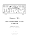
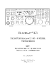
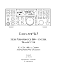
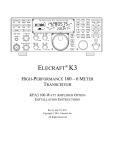
ELECRAFT K3
HIGH-PERFORMANCE
160 – 6 METER TRANSCEIVER
OWNER’S MANUAL
Revision D10, August 24, 2011
Copyright © 2011, Elecraft, Inc.
All Rights Reserved
Contents
A Note to K3 Owners ..................................... 3
Key to Symbols and Text Styles ..................... 3
Quick-Start Guide........................................... 4
Introduction.................................................... 7
Buffered I.F. Output............................................ 39
Using Transverters .............................................. 39
Scanning .............................................................. 40
Main and Sub Receiver Antenna Routing..... 41
Basic K3 (no KAT3 or KXV3)........................... 41
K3 with KXV3 RF I/O Module .......................... 41
K3 with KAT3 ATU ........................................... 42
K3 with KAT3 and KXV3.................................. 43
K3 Features ............................................................7
Specifications .........................................................8
Customer Service and Support ............................10
Front Panel ................................................... 11
Control Groups.....................................................11
Display (LCD)......................................................12
LEDs.....................................................................13
Front Panel Connectors........................................13
Primary Controls ..................................................13
Multi-Function Controls ......................................14
VFO Tuning Controls ..........................................14
Keypad..................................................................15
Memory Controls .................................................16
Message Record/Play Controls............................16
RIT and XIT Controls..........................................16
Remote Control of the K3 ............................ 44
Options and Accessories .............................. 45
Firmware Upgrades...................................... 45
Configuration............................................... 46
Rear Panel .................................................... 17
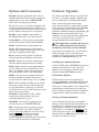
Synthesizer .......................................................... 49
Wattmeter ............................................................ 49
Transmitter Gain ................................................. 49
Reference Oscillator............................................ 50
Front Panel Temperature Sensor ........................ 51
PA Temperature Sensor ...................................... 51
S-Meter and RF GAIN Control .......................... 51
Crystal Filter Setup ............................................. 46
Option Module Enables ...................................... 47
Miscellaneous Setup ........................................... 47
VFO A Knob Friction Adjustment ..................... 48
VFO B Knob Friction Adjustment ..................... 48
Real Time Clock Battery Replacement .............. 48
Calibration Procedures ................................. 49
Connector Groups ................................................17
KIO3 Module .......................................................18
Basic Operation ............................................ 21
Receiver Setup .....................................................23
Reducing Interference and Noise ........................25
Transmitter Setup.................................................26
Voice Modes (SSB, AM, FM).............................28
CW Mode .............................................................30
Data Modes ..........................................................31
Menu Functions ........................................... 52
MAIN Menu ........................................................ 52
CONFIG Menu.................................................... 53
Advanced Operating Features ....................... 33
Troubleshooting ........................................... 64
Text Decode And Display....................................33
CW-to-DATA.......................................................34
Tuning Aids: CWT and SPOT.............................34
Audio Effects (AFX)............................................35
APF and Dual-Passband CW Filtering................35
Receive Audio Equalization (EQ) .......................35
Transmit Audio Equalization (EQ) .....................35
SPLIT and Cross-Mode Operation......................36
Extended Single Sideband (ESSB)......................36
General-Coverage Receive ..................................36
VFO B Alternate Displays...................................36
Alarm and Auto Power-On..................................36
Using the Sub Receiver........................................37
Receive Antenna In/Out.......................................39
Parameter Initialization....................................... 66
Module Troubleshooting..................................... 67
Theory Of Operation .................................... 71
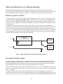
RF BOARD ......................................................... 71
KAT3 (ATU) and KANT3 ................................. 73
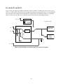
KIO3 (AF/Digital I/O) ........................................ 73
Front Panel and DSP ........................................... 73
KREF3 (Ref./2nd LO) .......................................... 74
KSYN3 (Synthesizer) ......................................... 75
Firmware.............................................................. 75
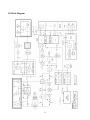
K3 Block Diagram .............................................. 76
Appendix A: Crystal Filter Installation......... 77
Index............................................................ 81
2
A Note to K3 Owners
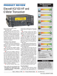
On behalf of our entire design team, we’d like to thank you for choosing the Elecraft K3 transceiver.
The K3—like its predecessor, the K2—reflects our desire to go beyond what other high-performance
transceivers have offered. It isn’t just a home-station rig; at about 8 to 9 pounds, it can accompany you
wherever you go, whether it’s out to your back porch or halfway around the world. And it’s the only
rig in its class that you can build yourself. Above all, we want the K3 to be ready for any operating
situation you encounter, and to be more enjoyable to use than any transceiver you’ve ever owned.
In addition to this manual, you’ll find much more information on the K3 on our web site, including
operating tips, answers to frequently asked questions, and information on firmware upgrades and
accessories.
73,
Wayne, N6KR
Eric, WA6HHQ
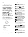
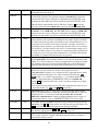
Key to Symbols and Text Styles
Important – read carefully
Operating tip
LS B
LCD icon or characters
LED
.
.
Enter keypad function
XMIT
Tap switch function (labeled on a switch)
TUNE
Hold switch function (labeled below a switch; hold for 1/2 sec. to activate)
SQL
Rotary control without integral switch
PWR
Tap switch function of rotary control (labeled above a knob)
MON
Hold switch function of rotary control (labeled below a knob; hold for 1/2 sec.)
MAIN:VOX GN
Typical MAIN menu entry
CONFIG:KAT3
Typical CONFIG menu entry
3
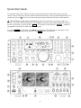
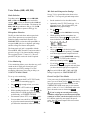
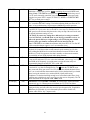
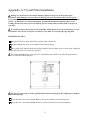
Quick-Start Guide
To get started using your K3 right away, please read this page and the two that follow, trying each of the
controls. The text uses braces to refer to numbered elements in the front- and rear-panel illustrations below. For
example, {1} refers to 1 , the mic jack. Later sections provide greater detail on all aspects of K3 operation.
The first thing you need to know about the K3 is that most switches have two functions. Tap (press
briefly) to activate the function labeled on a switch. Hold to activate the function labeled below the switch. In
the text, tap functions are shown like this: M E N U . An example of a hold function is C O N F I G . Additional
typographical conventions are shown on the previous page.
Try tapping M E N U {8}. This brings up the MA I N menu. Rotating VFO B {19} selects menu entries, while
rotating VFO A {22} changes their parameters. Tap M E N U again to exit the menu.
4
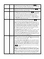
Connections
•
•
•
•
Connect a power supply to the DC input jack {26} (see Specifications, pg. 8).
On the K3/100, a circuit breaker is provided on the fan panel for the 100-W stage {38}.
You can power an accessory device from the switched DC output jack {39} (0.5 A max).
Connect an antenna to ANT1 {29}. With an ATU (pg. 22), you can also use ANT2 {28}.
AUX RF {27} is for the sub receiver; see pg. 17. ANT3 {30} is used with the internal 2-m
module (K144XV). With a KXV3, you can connect an RX antenna to RX ANT IN {34}.
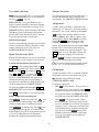
The Basics
•
•
Press P O W E R {5} to turn on the K3. If there are any error indications, refer to pg. 68.
T A P and H O L D Functions: Tapping briefly activates the function labeled on a switch.
Holding for about 1/2 second activates the function labeled below a switch.
Tap either end of B A N D {7} to select a band, and tap M O D E {6} to select the mode. Set
the AF gain using
AF {2}. Set
RF to max. SU B controls are discussed on pg. 37.
The large knob {22} controls VFO A (upper display, {10}). The medium knob {19}
controls VFO B (lower display, {11}). VFO A is main RX/TX except in SPLIT (pg. 36).
C MP / PW R is one of four multifunction controls {24}. Each has two primary
functions, indicated by green LEDs. The knob has a built-in switch; tap it to select either
C MP (compression level) or PW R (power output). Hold the knob in to access its
secondary function, MO N itor level. Tap again to restore the primary function.
•
•
•
•
Rotate the
SHIFT / LOCUT and
HICUT / WIDTH controls {23} to adjust the filter
passband. Crystal filters FL1 -FL5 are automatically selected as you change the
bandwidth. Tap either knob to alternate between shift/width and hicut/locut.
•
•
•
Hold
SHIFT / LOCUT to N O R M alize the bandwidth (e.g., 400 Hz CW, 2.8 kHz SSB).
Hold
HICUT / WIDTH to alternate between two filter setups, I and II (per-mode).
Tap X F I L {13} to select crystal filters manually; this also removes any passband shift.
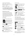
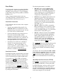
Voice Modes
•
{1}
•
•
•
•
Hold M E T E R {8} to see C MP / A LC levels. While talking, set
MIC {25} for 4-7 bars
of ALC, and
CMP for the desired compression. Then return to SW R / PW R (pg. 28).
Optional: Hold T E S T {6} for TX TEST mode; allows off-air TX adjustments (pg. 13).
Hold
CMP / PWR {24} to set speech MO N itor level; tap to return to C MP / PW R .
Hold V O X {7} to select PTT or VO X . Hold
SPEED / MIC to set VOX D EL A Y .
Details: VOX, pg. 29; TX EQ, pg. 35; MIC SEL, pg. 52; SSB/AM/FM, pg. 28.
Filter
Controls
CW Mode
{36}
Data Modes
{31}
•
•
•
•
•
•
•
•
•
•
SPEED {25} sets the CW keyer speed. Hold this knob to set semi-break-in D EL A Y .
Hold Q S K {7} to select full Q SK (pg. 30.). Hold VO X {7} to select hit-the-key CW.
Hold P I T C H {18} to set sidetone pitch. Hold
CMP / PWR to set sidetone MO N level.
Tap C W T {18} for tuning aid {9} (pg. 34). With C W T on, S P O T auto-spots (pg. 30).
To select CW text decode/display mode, hold T E X T D E C {18}; rotate VFO B (pg. 30).
CW keying is converted to DATA in FSK D and PSK D modes (below and pg. 34).
Hold D U A L P B {13} to turn on audio peaking (APF) or dual-passband filtering (pg. 30).
Tap M O D E {6} until you see the D A T A icon turn on (see Data Modes, pg. 31).
Hold D A T A M D {18}. Use VFO B to select from: D A T A A (PSK31 & other
soundcard-based modes), A FS K A (soundcard-based RTTY), FSK D (RTTY via data
input or keyer), or PSK D (PSK via data input or keyer). VFO A selects data baud rate
for internal encoder/decoder, if applicable. D U A L P B turns on RTTY filter (DTF, pg. 32).
Hold P I T C H {18} to select mark tone and shift (for encoder/decoder and RTTY filter).
Hold T E X T D E C {18} to set up text decode. C W T shows tuning aid (pg. 34).
5
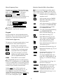
VFOs
and RIT/XIT
•
•
•
•
•
{21} selects 10 or 50 Hz VFO/RIT tuning. See VFO menu entries, pg. 53.
{21} selects 1-Hz steps. C O A R S E selects large steps (MAIN menu, VFO CRS).
Tap F R E Q E N T {21} to enter frequency in MHz using numeric keypad & decimal point.
Tap return (
) to complete the entry, or tap F R E Q E N T again to cancel. (Pg. 15.)
Hold S C A N to start/stop scanning. S C A N must be preceded by a memory recall (pg. 40).
The R I T and X I T offset knob {17} has LEDs that show -/0/+ offset (pg.16). Tap C L R
{16} to zero the offset. Hold C L R for > 2 sec. to add the offset to VFO A, then zero it.
RATE
FINE
Transmit,
ATU, and
Antenna
Controls
•
NB, NR,
and Notch
•
Tap N B {12} to enable DSP and I.F. noise blanking. Hold L E V E L to set DSP NB level
(VFO A) and I.F. NB level (VFO B). Fully CCW is OFF in both cases. (Pg. 25.)
•
Tap N R {12} to turn on noise reduction (saved per-mode). Hold A D J to tailor noise
reduction for the present band conditions (pg. 25).
•
Tap N T C H {12} once to select auto-notch (N TC H icon), and a second time to select
manual notch (adds
icon). Hold M A N to adjust manual notch frequency. (Pg. 25.)
SPLIT,
BSET,
and SUB
•
Hold S P L I T {13} to enter split mode (RX on VFO A, TX on VFO B). If VFOs A and B
are on different frequencies in SPLIT mode, the Delta-F LED (∆f ) will turn on (pg. 13).
Hold B S E T {13} to adjust VFO B / sub RX settings independently of VFO A (pg. 37).
Tap S U B {20} to turn on the sub receiver (pg. 37). VFO B controls its frequency.
Hold S U B {20} to link the two VFOs (VFO A is then the master). A 2-second hold of
S U B engages diversity mode (pg. 38). SPLIT operation is possible in diversity mode.
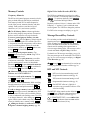
Memories,
Messages, and
DVR
•
•
•
•
•
•
•
•
Menus and
Switch Macros
•
•
Other
Features
The TX LED {4} indicates that the K3 is in transmit mode. The ∆f LED turns on if the
RX and TX frequencies are unequal (S P L I T , R I T / X I T , cross-mode, etc.). (Pg. 13.)
X M I T {8} is equivalent to PTT {35}. T U N E puts out full CW power in any mode.
A T U T U N E {8} initiates antenna matching (pg. 22). A T U enables or bypasss the ATU.
A N T selects A N T 1 or A N T 2 . R X A N T selects main or R X antenna (KXV3).
To store a frequency memory, tap V M {14}, then: tap M 1 - M 4 {15} to save a per-band
quick memory; or tap 0 - 9 to save a general-purpose quick memory; or rotate VFO A to
select from memories 0-99, then tap V M again to save. Tap M V to recall. (Pg. 16.)
R E C and M 1 - M 4 {15} are also used to record & play voice/CW/DATA messages. The
KDVR3 option is required for voice messages and A F R E C / A F P L A Y (pg. 29).
M E N U & C O N F I G {8} access the MAIN and CONFIG menus. VFO B selects entries;
VFO A changes parameters. In general, CONFIG menu entries are used less often.
Tapping D I S P {8} within menus shows information about each entry on VFO B (pg 52).
•
Menu entries can be assigned to programmable switches P F 1 , P F 2 {16} and M 1 - M 4 {15}
(pg 52). These switches can also execute often-used macros like “SPLIT, A>B, move VFO
B up 5,” with a single tap or hold. See the K3 Programmer’s Reference for examples.
•
•
•
•
RX and TX EQ (MAIN menu) provide 8 bands of receive/transmit equalization (pg. 35).
Tap A F X {18} to enable the selected audio effect (see CONFIG:AFX MD, pg. 52).
Tap D I S P {8} and use VFO B to show time, supply voltage, etc. on VFO B (pg. 36).
The ALARM function (MAIN:ALARM menu entry) can be used to remind you about a
contest, net, or QSO schedule, and can even turn the K3 on at alarm time (pg. 36).
The KIO3 module provides a rich set of AF {33} and digital {32} I/O (pg. 17).
•
6
Introduction
This comprehensive manual covers all the features
and capabilities of the Elecraft K3 transceiver. We
recommend that you begin with the Quick-Start
Guide (pg. 4). The Front Panel (pg. 11) and Rear
Panel (pg. 17) sections are for general reference.
Basic Operation (pg. 21) and Advanced
Operation (pg. 33) fill in the details.
•
•
•
•
Anytime you add new filters or options, refer to
Configuration (pg. 46).
User Interface
K3 Features
•
The K3 offers a number of advanced features to
enhance performance and versatility:
•
Receiver
•
•
•
•
•
•
Up to five crystal roofing filters with
bandwidths as narrow as 200 Hz (pg. 23)
High-performance, fully independent sub
receiver, also with up to five crystal filters,
allows true diversity receive with two
antennas (pg. 37)
Variable-bandwidth crystal filters that track
DSP filter settings
Narrow ham-band front-end filters, plus
wider band-pass filters for general-coverage
receive (pg. 45)
•
•
•
•
•
•
•
•
•
•
•
•
32-bit I.F. DSP for advanced signal
processing, including full stereo and other
binaural effects (pg. 35)
Passband tuning and programmable
DSP/crystal filter presets (pg. 14)
8-band transmit and receive EQ (graphic
equalization) (pg. 35)
Versatile digital voice recorder (DVR) for
incoming/outgoing audio streams (pg. 29)
Enhanced remote control (pg. 44)
Firmware upgrades via the Internet (pg. 45)
Isolated PC audio input/outputs (pg. 17)
Front and rear mic and headphone jacks
Full stereo audio with two speaker outputs
Options and Accessories (pg. 45)
•
CW and Digital Modes
•
Dual VFOs with independent modes,
bands, and filter settings (pg. 14)
100 memories with alphanumeric labels,
plus 4 quick-memories per band (pg. 16)
Dedicated message play controls for use in
CW, data, and voice modes (pg. 30)
Real-time clock/calendar with alarm and
automatic power-on (pg. 36)
Utility displays show voltage, current drain,
RIT/XIT offset, front panel temperature,
PA heatsink temperature, etc. (pg. 36)
Built-in help menu help text (pg. 21)
Programmable switch “macros” to
automate often-used operations (pg. 44)
Custom “sign-on banner” can be displayed
on power-up (via the K3 Utility program)
Connectivity
DSP
•
APF (audio peaking filter) for digging out
weak signals in CW mode (pg. 30)
Internal CW-to-RTTY or CW-to-PSK31
encoding for casual digital-mode QSOs
without a computer (pg. 34)
CW decoded and displayed as you send –
great for improving CW skills (pg. 33)
Automatic CW/data signal spotting and
manual fine-tuning display (pg. 30)
•
Built-in digital-mode demodulation with
text displayed on the K3’s LCD (CW,
RTTY, PSK31) (pg. 33)
7
ATU, sub receiver, digital voice recorder,
100-W PA, 2-meter module, external
reference lock, and other internal options
KPA500 amplifier, P3 Panadapter, PR6 sixmeter preamp and other accessories
Specifications
Some specifications apply only if the corresponding option modules are installed (see Options, pg. 45).
GENERAL
Frequency Range
Main and Sub Receivers, 490 kHz - 30 MHz and 44-54 MHz. Transmitter: Amateur
bands between 1.8 and 54 MHz (varies by country). 144-148 MHz with K144XV
option.
MARS coverage on request (excluding transmit from 7.550-8.999 MHz at 13 W and
higher, and 7.650-8.999 MHz at 12 W or lower).
Tuning Step Sizes
1, 10, 20, and 50 Hz fine steps; user-configurable coarse tuning steps (per-mode).
Direct keypad frequency entry in either MHz or kHz.
Memories
100 general purpose, plus 4 scratch-pad memories per band
Frequency Stability
+/- 5 ppm (0-50 C) TCXO standard; +/- 1 ppm TCXO opt. (+/- 0.5 PPM typ., 0-50 C).
K3EXREF option locks TCXO to an external 10-MHz reference (+/- 1 to 2 Hz typ.).
Antenna Jacks
50 ohms nominal. One SO-239 supplied (2nd SO-239 jack supplied with KAT3 ATU).
BNC jacks for RX antenna in/out and transverter in/out (KXV3 Option).
Modes
USB, LSB, AM, FM, CW, DATA (FSK D [direct], AFSK A [Audio], PSK D [Direct]
and DATA A [Audio]; PSK). Built in PSK, RTTY, and CW text decode/display.
VFOs
Dual VFOs (A and B) with separate weighted tuning knobs
Remote Control Port
EIA-232 standard DE-9F; USB adapter option. Full control of all radio functions.
Audio I/O
Line-level isolated TX/RX audio interface (stereo outputs); front (1/4”) and rear (1/8”)
stereo headphone jacks; stereo speaker jack.
Transverter Interface
Transmit, 0 dBm typ.; BNC in/out connectors on KXV3 option module. KXV3A
(updated KXV3) includes connectors for K144XV internal 2-meter module.
Buffered IF output
BNC connector (KXV3 Option); see pg. 39 for interface recommendations.
Other I/O
Key/Keyer/Computer, Paddle, PTT In, and KEY Out. Band information output via
binary interface and AUXBUS on ACC connector.
Real-Time Clock/Calendar
Accuracy: Approx. +/- 20 ppm (+/- 2 seconds/day). U.S. and E.U. date formats.
Battery: 3 V coin cell (see pg. 48 for replacement instructions).
Supply Voltage
and Current
13.8 V nominal (11 V min, 15 V max). 17-22 A typical in TX for K3/100, 3-4 A
typical in TX for K3/10. 0.9A typical RX (less sub receiver). When using reduced
supply voltage (< 12 V), power output should be reduced (e.g. 70 W at 11 V).
Recommended supply: 13.8VDC @ 25A, continuous duty for K3/100; 13.8VDC @
6A for K3/10. For best results, use the supplied 5 foot (1.53 m) power cable. When a
battery is used, both sides of the battery cable should be protected by fast-blow fuses.
Accessory DC output
Switched, 0.5 A max; 13 V no-load, 12 V max load (@ Vsupply = 13.8 V)
Weight (K3/100)
Approx. 8.5 lbs. (3.8 kg). With KRX3 sub receiver option, 9.5 lbs. (4.3 kg).
Size
Enclosure only, 4.0 x 10.7 x 10.0 in., HWD (10.2 x 27.2 x 25.4 cm). With projections,
4.4 x 11.1 x 11.8 in. (11.2 x 28.2 x 30.0 cm).
8
RECEIVER (Main and Sub)*
Sensitivity (MDS)
-136 to -138 dBm (typ.), preamp on, 500 Hz bandwidth. 6 m MDS with PR6 option:
-143 to -144 dBm (typ.). Reduced sensitivity near 8.2 MHz (first I.F.) and from 4449.5 MHz. Sensitivity decreases gradually below 1.8 MHz due to intentional highpass response at the T-R switch. (Use RX ANT input or sub receiver’s AUX input to
avoid the high-pass filter loss.) Note: KBPF3 option required for full general
coverage (including 0.49 to 1.7 MHz).
Dynamic Range
IMD3 > 100 dB, Blocking 140 dB, typical (at 5, 10, and 20 kHz spacing)
Image and I.F. Rejection
> 70 dB
Audio Output
2.5 W per channel into 4 ohms; typ. 10% THD @ 1 kHz, 2 W
S-Meter
Nom. S9 = 50 µV, preamp on; user-adjustable
Noise Blanker
Adjustable, multi-threshold/multi-width hardware blanker plus DSP blanker
Receive AF graphic EQ
+/- 16 dB/octave, 8 bands
Filter Controls
IF Shift/Width & Lo/High Cut with automatic crystal filter selection
* Receive specifications are guaranteed only within ham bands. Dynamic range measurements based on 400-Hz, 8-pole
filter. Other available filters have very similar performance; see www.elecraft.com for full list.
TRANSMITTER *
Output Power
K3/100: 0.1 W –100 W typ. Suggested max from 51-52 MHz, 85 W; 52-54, 70 W.
K3/10 (or K3/100 with PA bypassed): 0.1 W –12 W, HF-10 m; 8 W max on 6 m.
XVTR OUT (KXV3 option): -10 to +1.8 dBm. K144XV: ~10 W, 144-148 MHz.
Note: Output can be set up to 110 W. However, IMD and spurious products are
specified at 100 W, the recommended max. If a KAT3 ATU is installed, actual
output will be slightly lower (typ. loss < 0.5 dB below 28 MHz, < 0.8 dB above).
Duty Cycle
CW and SSB modes, 100% 10-min. 100W key-down at 25 C ambient
True RF Speech Processor
Adjustable compression
Transmit AF graphic EQ
+/- 16 dB/octave, 8 bands
SSB TX Bandwidth
4 kHz max (> 2.8 kHz requires 6 kHz AM filter)
SSB TX Monitor
Post-DSP filtering/processing
VOX
DSP-controlled, adjustable threshold, delay, and anti-VOX
Full and Semi CW Break-In
Adjustable delay; diode T/R Switching
SSB Carrier Suppression
> 50 dB
Harmonic / Spurious Outputs
> 50 dB below carrier @ 100W (> 60 dB on 6 meters)
CW Offset/Sidetone
300-800 Hz, adjustable (filter center frequency tracks sidetone pitch)
Mic Connector
Front panel, 8 pin; rear panel 3.5 mm. Switchable DC bias (MAIN:MIC SEL)
* Transmit specifications are guaranteed only within ham bands.
9
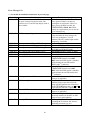
Customer Service and Support
Technical Assistance
You can send e-mail to [email protected] and we will respond quickly – typically the same day
Monday through Friday. If you need replacement parts, send an e-mail to [email protected]. Telephone
assistance is available from 9 A.M. to 5 P.M. Pacific time (weekdays only) at 831-763-4211. Please use e-mail
rather than calling when possible since this gives us a written record of the details of your problem and allows us
to handle a larger number of requests each day.
Repair / Alignment Service
If necessary, you may return your Elecraft product to us for repair or alignment. (Note: We offer unlimited email
and phone support, so please try that route first as we can usually help you find the problem quickly.)
IMPORTANT: You must contact Elecraft before mailing your product to obtain authorization for the
return, what address to ship it to and current information on repair fees and turn around times. (Frequently we
can determine the cause of your problem and save you the trouble of shipping it back to us.) Our repair location
is different from our factory location in Aptos. We will give you the address to ship your kit to at the time of
repair authorization. Packages shipped to Aptos without authorization will incur an additional shipping charge
for reshipment from Aptos to our repair depot.
Elecraft 1-Year Limited Warranty
This warranty is effective as of the date of first consumer purchase (or if shipped from the factory, the date the
product is shipped to the customer). It covers both our kits and fully assembled products. For kits, before requesting
warranty service, you should fully complete the assembly, carefully following all instructions in the manual.
Who is covered: This warranty covers the original owner of the Elecraft product as disclosed to Elecraft at the time
of order. Elecraft products transferred by the purchaser to a third party, either by sale, gift, or other method, who is
not disclosed to Elecraft at the time of original order, are not covered by this warranty. If the Elecraft product is being
bought indirectly for a third party, the third party’s name and address must be provided at time of order to ensure
warranty coverage.
What is covered: During the first year after date of purchase, Elecraft will replace defective or missing parts free of
charge (post-paid). We will also correct any malfunction to kits or assembled units caused by defective parts and
materials. Purchaser pays inbound shipping to us for warranty repair; we pay shipping to return the repaired
equipment to you by UPS ground service or equivalent to the continental USA and Canada. For Alaska, Hawaii, and
other destinations outside the U.S. and Canada, actual return shipping cost is paid by the owner.
What is not covered: This warranty does not cover correction of kit assembly errors. It also does not cover
misalignment; repair of damage caused by misuse, negligence, or builder modifications; or any performance
malfunctions involving non-Elecraft accessory equipment. The use of acid-core solder, water-soluble flux solder, or
any corrosive or conductive flux or solvent will void this warranty in its entirety. Also not covered is reimbursement
for loss of use, inconvenience, customer assembly or alignment time, or cost of unauthorized service.
Limitation of incidental or consequential damages: This warranty does not extend to non-Elecraft equipment or
components used in conjunction with our products. Any such repair or replacement is the responsibility of the
customer. Elecraft will not be liable for any special, indirect, incidental or consequential damages, including but not
limited to any loss of business or profits.
10
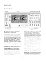
Front Panel
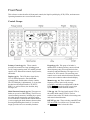
This reference section describes all front panel controls, the liquid crystal display (LCD), LEDs, and connectors.
Operating instructions are covered in later sections.
Control Groups
Primary Controls (pg 13): These controls
provide basic transceiver setup, including power
on/off, band, operating mode, AF and RF gain and
squelch, ATU and transmit controls, display modes,
and menus.
Keypad (pg. 15): This group of switches is
numbered for use during memory store/recall and
direct frequency entry, but each switch also has
normal tap and hold functions. The upper row of
switches are VFO controls. The remaining rows
control receive-mode and miscellaneous functions,
such as noise reduction and text decode/display.
Display (pg 12): The LCD shows signal levels,
VFO A and B frequencies, filter bandwidth,
operating mode, and the status of many controls.
The VFO B display is alphanumeric, so it can show
decoded text from digital modes (CW, RTTY,
PSK31), as well as menus, time and date, help
messages, etc.
Memories (pg. 16): These switches control
frequency memory store/recall, message
record/play, and audio record/playback (with the
DVR). M 1 - M 4 can also be used as up to eight
tap/hold programmable function switches.
Multi-Function Controls (pg. 14): The upper two
knobs set up receiver DSP filtering. The lower two
control transmit parameters, including keyer speed,
mic gain, speech compression, and power output
level. LEDs above each knob show which function
is active; tapping the knob alternates between them.
Pressing and holding these knobs (1/2 second or
longer) provides access to secondary functions.
VFOs (pg. 14): The large knob controls VFO A;
the smaller knob controls VFO B. The four
switches between the VFO knobs select tuning rates
and control related functions.
RIT/XIT (pg. 16): Three switches control RIT and
XIT on/off and clear (offset zero). The knob below
the R I T / X I T switches selects the offset.
11
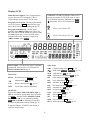
Display (LCD)
Multi-character displays: The 7-segment display
(upper) shows the VFO A frequency. The 13segment display (lower) shows VFO B or text.
VFO Icons: The TX icon indicates which VFO is
selected for transmit. In TX TEST mode, or when
TX is inhibited externally, TX flashes (see T E S T ).
Shows that VFO A or B is locked (see L O C K ).
Bar graph, receive mode: The bar graph normally
acts as an S-meter. If C W T is turned on, the right
half of the S-meter becomes a tuning aid (pg. 34).
A
VFO A is the transmit VFO
Bar graph, transmit mode: The bar graph
normally shows SW R and R F power output. The
R F scale will be either 5 and 1 0 (low power) or 5 0
and 1 0 0 (high power). In voice and data modes,
transmit scales can be changed to compression
(C MP ) and A LC using M E T E R .
TX
Filter Graphic: This shows the approx. bandwidth
and position of the receiver’s I.F. passband. See
Filter Passband Controls, pg. 23.
Other Icons:
TX
B
Notch filtering on ( N T C H , pg. 25)
Manual notch (M A N , pg. 25)
I / II
Shows selected preset (I/ I I , pg. 14)
XFIL
Crystal filter selection (FL1 -FL5 )
SPLIT
CW/data tuning aid on ( C W T , pg. 34)
DVR in use (A F R E C / A F P L A Y , pg. 16)
VO X VOX enabled (V O X , pg. 13)
Q SK Full break-in CW enabled (Q S K , pg. 30)
NB
Noise blanker on ( N B , pg. 15)
NR
Noise reduction on ( N R , pg. 15)
A N T Antenna 1 or 2 ( A N T , pg. 13)
RX
RX antenna in use ( R X A N T , pg. 13)
A TT
Attenuator on (A T T , pg. 15)
PR E Preamp on (P R E , pg. 15)
A TU ATU enabled (A T U , pg. 13)
R IT
RIT on ( R I T , pg. 16)
XIT
XIT on ( X I T , pg. 16)
SU B Sub receiver on ( S U B , pg. 37)
SPL T Split mode in effect (S P L I T , pg. 36)
CWT
Filter Icons:
N TC H
VFO B is the transmit VFO; see
Mode Icons:
Basic modes (LSB / U SB , C W , D A T A , A M , or
FM ) are selected by tapping either end (Up/Down)
of M O D E . Alternate modes (C W R EV , D A T A
R EV , A M- S , FM +/- ) are selected by holding
A L T . LSB and U SB are alternates of each other.
+ icon on in SSB modes indicates ESSB (pg. 36).
T indicates FM/tone, CW/DATA text decode, or
AM-Sync auto-tracking.
12
LEDs
Primary Controls
TX [Red] Turns on in transmit mode.
B A N D Tap left/right end to move among ham
bands. CONFIG:BND MAP disables bands. For
“quick” band switching, see CONFIG:MEM 0-9.
V O X Selects voice-operated or CW keyingoperated transmit (VO X icon on), or PTT (VO X
icon off). Also see
D E L A Y (pg. 30) and CW
VOX auto-off control (CONFIG:CW WGHT).
∆ F [Yellow] The Delta-F LED turns on if
transmit and receive frequencies or modes are
different due to the use of SPLIT, RIT, or XIT.
[Green] Eight LEDs show which functions are
in effect for the Multifunction Controls (pg. 14).
( + ) RIT/XIT OFFSET If the
offset control is centered, or you tap C L R , the
green LED turns on (offset = 0). Otherwise, the
yellow (-) or (+) LED will be on, indicating the
direction of the offset. See R I T , X I T , and C L R .
(-)
QSK
Front Panel Connectors
Tap the left or right end of this switch to
select the operating mode. When D A T A is selected,
the D A T A M D switch is used to specify DATA-A,
AFSK A, FSK D, or PSK D (pg. 31).
Selects either full break-in (Q SK icon on) or
semi break-in keying, if VOX is selected in CW
mode. Also see
D E L A Y (pg.30).
MODE
In LSB mode, switches to U SB (and viceversa). Also selects alternate modes, including:
C W R EV , D A T A R EV , and A M- S (pg. 29). In
FM mode, selects + /- or simplex (pg. 29).
ALT
PHONES You can use either mono or stereo
headphones at either the front- or rear-panel
headphone jack. Also see A F X (pg. 35).
MIC An Elecraft MH2, MD2, Proset-K2, or other
compatible mic can be used (see pinout below). To
select the front- or rear-panel mic, and to turn bias
on/off, use the MAIN:MIC SEL menu entry.
Bias must be turned on for electret mics (e.g. MH2,
MD2, Proset). It must be off for dynamic mics (e.g.
Heil mics using HC4 or HC5 elements).
Selects TX TEST (TX LCD icon flashing);
allows key/mic test without actually transmitting.
TEST
P O W E R Turns the K3 on or off. Note: To ensure
correct save of operating parameters, turn the
K3 off before turning the power supply off.
MENU
Displays MAIN menu (pg. 21).
CON FIG
Displays the CONFIG menu (pg. 21).
X M I T Manually-operated transmit. Places the K3
into transmit mode (same as PTT, pg. 26).
Puts out a carrier at the present power level.
Also TUNE Power Level (pg. 27).
TUNE
R X A N T Enables the receive antenna (pg. 22). If
the sub RX is on, holding R X A N T alternates
between the sub’s MA I N / A U X antennas (pg. 37).
Mic jack, viewed from front of K3
1 Mic audio, low-Z (~600 ohms)
2 PTT
3 DOWN button *
4 UP button *
5 FUNCTION button *
6 8V (10 mA max)
7, 8 Ground
D I S P Shows an alternate display on VFO B, such
as time, date, voltage, etc. (pg. 36).
M E T E R Selects voice transmit bar graph modes:
SW R and R F , or C MP and A LC (pg. 28).
Matches the antenna (transmitting at
up to 10 W) using the KAT3 ATU (pg. 22).
ATU TUNE
Puts the ATU into normal mode (A TU icon
on) or bypass mode (pg. 22).
ATU
* See CONFIG:MIC BTN menu entry.
A N T Selects A N T 1 or 2 . In BSET mode with the
sub receiver on, selects MA I N or A U X antenna for
the sub receiver (pg. 37).
FP ACC This connector (RJ-45, 6 pins) is located
on the bottom of the transceiver, near the VFO B
knob. It is used with accessory devices.
13
Dual-Concentric Potentiometers
Transmit Controls
AF — SUB AF gain controls for main
receiver (inner, or smaller knob) and sub receiver
(outer ring, or larger knob).
The primary functions of the transmit controls are:
SPEED
RF / S Q L — SUB RF gain (and/or squelch)
controls for main and sub receiver.
MIC
CMP
Two menu entries are provided to control squelch
directly: CONFIG:SQ MAIN, and SQ SUB. They
can also be used to reconfigure the RF gain controls
as squelch for either receiver, and to select FM-only
or all-mode squelch. See Config Menu (pg. 53).
PWR
The present transmit mode determines which
primary functions normally apply; for example, in
CW mode, the
S P E E D / M I C control defaults to
S P E E D . You can always tap a knob to override
the present selection.
Multi-Function Controls
The secondary functions of these controls are:
VOX delay (voice/data) or CW semibreak-in delay, in seconds
MON
Voice or data monitor level or
CW/data sidetone level
You can optionally LOCK the MIC, CMP, and
PWR control settings; see CONFIG:PWR SET.
The upper two multi-function controls set up
receiver filtering. The lower two controls adjust
transmit settings. Each control has two primary
functions (white labels) and a secondary function
(yellow). Tap a control knob to alternate between
its primary functions, indicated by two LEDs. Hold
a knob (~1/2 second or longer) to select its
secondary function.
DELAY
VFO Tuning Controls
Filter Controls
VFO A controls the upper frequency display. This
is normally the RX and TX frequency. In SPLIT
mode, VFO B controls the transmit frequency (pg.
36). VFO B also controls the sub receiver (pg. 37).
The primary functions of the filter controls are:
SHIF T
LO CUT
HI CUT
WIDT H
Shift passband either direction
Adjust low-frequency response
Adjust high-frequency response
Adjust width of the passband
The controls to the right of VFO A include:
As these settings change, so does the filter graphic.
Crystal filters are selected automatically (or
manually using X F I L , pg. 15). Also see Filter
Passband Controls (pg. 23).
Direct frequency entry (pg. 15)
SCAN
Start or stop scanning (pg. 40)
Select 1 Hz tuning for both VFOs
and RIT/XIT offset
C O A R S E Select coarse tuning rate (pg. 22)
RATE
Select one of two normal tuning rates
(10/50 or 10/20 Hz; pg. 22)
LOCK
Lock VFO A (use B S E T to lock B)
SUB
Tap to turn sub RX on/off (pg. 37).
Hold to link/unlink VFO A and B on
the present band (pg. 37). A long hold
(2 seconds or longer) enters diversity
mode (pg. 38).
Normalize passband
Normalizing the passband sets the bandwidth to a
fixed, per-mode value (e.g. 400 Hz in CW mode)
and centers the passband. (Also see user-defined
normal settings, N O R M1 /2 , pg. 24.)
I/ I I
FREQ ENT
FINE
The secondary functions of these controls are:
NORM
Keyer speed in WPM, 8-50 (8-100
if CONFIG:CW QRQ is O N )
Mic gain
Speech compression level
RF output power in watts (pg. 26)
Select preset I or II (per mode)
Presets I and II each hold a continuously-updated
DSP/crystal filter setup (pg. 24).
VFO A can optionally be coarse-tuned using
the RIT/XIT offset control if both R IT and XIT are
off . See CONFIG:VFO OFS.
14
Direct Frequency Entry
Receiver Control & Misc. (Lower Rows)
To jump to any frequency within the tuning range
of the K3, tap F R E Q E N T , then enter 1 to 3 MHz
digits, a decimal point, and 0 to 3 kHz digits.
Follow this with Enter ( . . ) to accept or
F R E Q E N T to cancel. The decimal point is
optional if no kHz digits are entered, making it very
easy to get to the low end of most ham bands.
Receiver control functions normally apply to
VFO A/main receiver. If B SE T is in effect, they
apply to VFO B (and the sub receiver if turned on).
PRE
Preamp on/off (6 m: see PR6, pg. 45)
ATT
Attenuator on/off
AGC
AGC slow/fast (also see CONFIG:
AGC DCY, AGC HLD, and other
AGC menu entries)
OFF
AGC off/on (when off, an AF limiter
is available; see CONFIG:AF LIM)
XFIL
Select next available crystal filter
(see CONFIG:FLx ON)
DUAL PB
CW: APF or Dual-passband filtering
(see CONFIG:DUAL PB);
RTTY: dual-tone filtering (pg. 30)
NB
Noise blanker on/off (pg. 25)
LEVEL
Noise blanker levels (pg. 25); use
VFO A knob to setup DSP blanker,
and VFO B to setup I.F. blanker
NR
Noise reduction on/off (pg. 25)
ADJ
Noise reduction parameter adjust; use
VFO B knob (pg. 25)
NTCH
Notch filter auto/manual/off (pg. 25)
MAN
Manual notch frequency (pg. 25); use
VFO B knob
SPOT
Spot tone on/off (manual), or autospot (if CWT is on; pg. 34)
PIT CH
CW sidetone PIT C H , PSK center
pitch, FSK / AFSK MARK tone and
shift (pg. 31), or FM tone setup (pg.
29)
CWT
CW/data tuning aid on/off (pg. 34);
turn on to use auto-spot
TEXT DEC
Text decode, CW or DATA (pg. 33);
use VFO B knob to select mode
AFX
Audio effects on/off (pg. 35); use
CONFIG:AFX MD to set mode
DATA MD
DATA mode selection (pg. 31); use
VFO B knob
Examples:
1.825 MHz: F R E Q E N T 1 . 8 2 5 .
1.000 MHz: F R E Q E N T 1
.
.
.
50.100 MHz: F R E Q E N T 5 0 . 1
.
If four or more digits are entered without a
decimal point, a value in kHz is assumed.
Keypad
Keypad switches have the tap and hold functions
listed below. They are also used for selecting quick
memories 0-9, and for direct frequency entry.
VFO Controls (Upper row)
The upper row of numeric keypad switches is used
to set up VFOs A and B. Their functions are:
A / B
Exchange VFO A and B contents
BSET
Set up VFO B and sub RX (see below)
REV
Exchange VFO A and B temporarily
(repeater RX/TX swap in FM-RPT)
A
B
SPL IT
Copy VFO A frequency to VFO B;
tapping twice copies all other settings
(also see CONFIG:VFO B->A)
Enable SPLIT receive/transmit
If cross-mode operation is not allowed for the
present VFO A and B modes, you’ll see SPL N /A
if you try to enable SPLIT. If cross-mode operation
is allowed, the mode icon for VFO B will flash as a
warning. Tap any switch to cancel the flash.
Holding B S E T allows VFO B (and the sub
receiver, if on) to be set up directly (pg. 37). As
long as B SE T is displayed, all VFO-related
controls and display elements apply to VFO B. An
alternative is to exchange VFOs with A / B , set up
VFO A, then exchange them again.
15
Memory Controls
Digital Voice/Audio Recorder (KDVR3)
Frequency Memories
The DVR can continuously record receive audio
(up to 90 seconds). To start/stop audio record, hold
A F R E C . To start/stop playback, hold A F P L A Y .
The
icon flashes during DVR use.
The K3 has 100 general-purpose memories (00-99),
plus per-band memories (M1-M4 on each band).
Each memory holds VFO A and B frequencies,
modes, filter presets, antenna selection, and other
settings. Each can have a text label of up to 5
characters (A-Z, 0-9, and various symbols).
Playback position (0-90 sec.) is shown on the VFO
B display; “*” appears if you’re within the most
recent segment. Use VFO B to change the position.
For DVR voice message record/play, see pg. 29.
The K3 Memory Editor software application
can be used to simplify setup and use of memories.
Refer to our K3 software web page for details.
Message Record/Play Controls
To store a general-purpose memory (0 0 -9 9 ):
First tap V M (VFO to Memory), then locate the
desired memory using the VFO A knob. The VFO
A frequencies stored in each memory will be shown
as you scroll through them. When you reach the
desired memory number, tap V M again to store,
or tap M V to cancel the operation.
Five switches provide record and playback of
outgoing messages: M 1 , M 2 , M 3 , M 4 and R E C .
These switches provide single-tap play, hold-torepeat, and other functions that are convenient for
contests and for sending often-repeated text or
voice messages during QSOs. CW messages can be
viewed and edited using K3 Utility, if desired.
To recall a general-purpose memory: Tap
M
V , then select memory 0 0 -9 9 using VFO A.
Tap M V again to exit.
For details on CW message record/play, see pg. 30.
The same messages can be used with CW-to-DATA
(pg. 34). For voice message record/play, see Digital
Voice Recorder (pg. 29).
Memories 00-09 are quick memories, accessible
with just two switch taps. These could be used to
get to a starting point in each of 10 ham bands.
Memories M 1 – M 4 are per-band quick memories.
For example, you might set up M 1 for each band’s
CW segment, M 2 for the SSB segment, etc.
through M 4 can alternatively be used as tap
or hold programmable function switches (pg. 21).
M1
RIT and XIT Controls
Memories 00-09 can act as if they were band
switches; see CONFIG:MEM 0-9.
To store or recall quick memories: Tap V M
or M V as before, but instead of rotating VFO A,
tap 0 - 9 or M 1 - M 4 .
To erase one or more memories: While scrolling
through memories to save or recall, tap C L R . Not
applicable to per-band quick memories ( M 1 - M 4 ).
To add or change a memory’s text label: First tap
M
V , then select a memory (0 0 -9 9 ) using VFO
A. Next, rotate VFO B to select each label position
in turn as indicated by the flashing cursor. Use VFO
A to change characters. After editing, tap M V
again. (Labels can be edited at any time, including
when you initially store a memory using V M .)
RIT
RIT (receive incremental tuning) on/off.
PF1
Programmable function switch (pg. 21)
XIT
XIT (transmit incremental tuning) on/off.
PF2
Programmable function switch (pg. 21)
CLR
Sets RIT/XIT offset to 0. Hold for 2
seconds to copy present RIT offset to VFO
A before clearing.
The RIT/XIT offset control sets the offset for R I T
and X I T . Three LEDs above the control show at a
glance whether an offset is in effect (pg. 11).
If CONFIG:RIT CLR is set to U N D O O N ,
tapping C L R will alternate between 0 .0 0 and the
last non-zero offset selected, if any.
Adding an asterisk (*) at the start of a label
designates a channel-hopping memory (pg. 40).
16
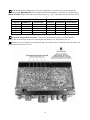
Rear Panel
Connector Groups
The appearance of your rear panel may vary
depending upon the options installed.
KIO3 (pg. 18): The KIO3 is an upgradeable digital
and audio I/O module providing computer and
auxiliary control signals, single or dual (stereo)
speaker outputs, line level in (mono) / out (stereo),
and supplemental headphone (stereo) and mic jacks.
Antennas: ANT1 (SO-239) is standard. ANT2
(SO-239) is supplied with the KAT3 ATU option,
which includes an antenna switch controlled from
the front panel. Both jacks are nominally 50 ohms
when the ATU is bypassed. AUX RF (BNC) is for
use with the KRX3 option; see pg. 37 and pg. 41.
ANT3 (BNC, on the KPA3 option panel) is the
antenna jack for the optional K144XV 2-m module.
KXV3: The KXV3 provides a variety of RF I/O
signals, including receive antenna in/out (pg. 41),
transverter in/out (pg. 39), and a buffered I.F.
output for use with panadapters such as the Elecraft
P3 (pg. 45). The KXV3A also includes internal IF
connections for the K144XV 2-m module.
DC: 12 VDC IN jack is an Anderson PowerPole
connector rated at 30 amps. (See Specifications, pg.
8, for detailed power requirements.)
Keying: PADDLE (1/4” phone jack) is the keyer
paddle input (see CONFIG:CW PDL menu entry).
KEY (1/4” phone jack) can be used with a hand
key, external keyer, computer, or other keying
device. PTT IN (RCA/Phono) is for use with a
footswitch or other external transmit control device.
KEY OUT (RCA/Phono) is the amplifier T-R relay
keying output, capable of keying up to +200VDC
@ 5A.
12 VDC OUT (RCA/Phono) provides up to 0.5 A
(switched) for use with accessory devices.
Ground Terminal: A good station ground is
important for safety and to minimize local RFI.
KPA3: This option panel is blank in the K3/10
except for ANT3 (see above). In the K3/100, the
blank panel is replaced with the fan panel shown,
which includes a circuit breaker.
REF IN (SMA): External 10-MHz reference input
for use with the K3EXREF option module (see
CONFIG:REF CAL and CONFIG:XVn OFS).
17
KIO3 Module
ACC (Accessory I/O)
The KIO3 provides serial I/O, control signals, audio
in/out for use with sound cards, speaker outputs,
and auxiliary headphone and mic jacks.
ACC connector pinouts are listed below.
ACC is not a VGA video connector. The K3
does not provide a video output.
RS232
The RS232 port can operate at up to 38,400 baud. A
straight-through cable is required. If you’re using an
Elecraft P3 Panadapter, the computer is connected
to the P3, and the P3 is connected to the K3.
Pin #
If you’re building your own cable, you can use as
few as three wires (RXD, TXD, and ground; see
table below). DTR and RTS are optional.
This table uses EIA standard descriptions,
which are from the perspective of the PC. These
differ from K2 documentation, even though the
connections are functionally identical.
Pin #
1,6,8,9
Description
Not used
2
RXD IN (data to PC from K3)
3
TXD OUT (data to K3 from PC)
4
DTR (see PTT and Keying, below)
5
Ground (RF isolated)
7
RTS (see PTT and Keying, below)
Description
1
FSK IN (see FSK Input)
2
AUXBUS IN/OUT (see KRC2 or XVSeries transverter instruction manual)
3
BAND1 OUT (see Band Outputs)
4
PTT IN (in parallel with MIC PTT)
5
Ground (RF isolated)
6
DIGOUT0 (see Transverter Control)
7
K3 ON signal (out) or TX INH (in)
(see Transverter Control, TX INH)
8
POWER ON (see pg. 44)
9
BAND2 OUT (see Band Outputs)
10
KEYOUT-LP (10 mA keying output)
11
DIGOUT1 (see DIGOUT1)
12
Ground (RF isolated)
13
BAND0 OUT (see Band Outputs)
14
BAND3 OUT (see Band Outputs)
15
EXT ALC input (see External ALC,
pg. 27)
RS232 Connector (female, on KIO3 panel)
Serial Port Setup: Set CONFIG:RS232 for the
desired baud rate. Software should be set up at the
same rate; 8 data bits, no parity, 1 stop bit.
ACC Connector (female, on KIO3 panel, viewed
from the back of the K3)
DTR and RTS: These are not used as serial I/O
handshaking lines. Instead, the K3 can use these as
PTT IN or KEY IN (see CONFIG:PTT-KEY). The
default for both signals is inactive. Refer to
application software documentation to determine if
it can use RS232 signal lines for PTT or keying.
FSK Input (for FSK D Data Mode)
If a PC or other device asserts RTS or DTR
while you’re using the PTT-KEY menu entry, the
K3 will enter TEST mode as a precaution.
DIGOUT1 is a per-band/per-antenna open-drain
output for controlling antenna switches, preamps,
filters, etc. See CONFIG:DIGOUT1.
This is a TTL input pulled up to 5V, compatible
with PC outputs. When used with an RS232 signal
from the PC, a level translator is required.
DIGOUT 1
18
Band Outputs (BAND0-BAND3)
BAND0-3 provide band selection signals. Their
behavior is controlled by the CONFIG:KIO3 menu
entry (see below). Band data is based on VFO A.
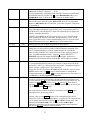
With CONFIG:KIO3 set to H F- TR N , the
BAND0-3 outputs follow the N O R table when HF6 m bands are selected, and the TR N table when a
transverter band is selected.
Earlier K3s may require external pullup
resistors to 5 V on these lines, typically 2.2-10K.
Transverter Control
In tables below, 0 = 0 VDC, and 1 = 5 VDC.
Normally, when the K3 is turned on, a 5-VDC logic
signal appears on ACC pin 7 (K3 ON). This could
be used with Elecraft XV transverters as an enable
signal (pin 8 of J6 on the transverter).
With CONFIG:KIO3 set to N O R , the BAND0-3
outputs are mapped based on the selected HF-6 m
band as shown below. On Transverter bands,
BAND0-3 will all be set to zero.
Band
160 m
80 m
60 m
40 m
30 m
20 m
17 m
15 m
12 m
10 m
6m
BAND3
0
0
0
0
0
0
0
0
1
1
1
BAND2
0
0
0
0
1
1
1
1
0
0
0
BAND1
0
1
0
1
0
0
1
1
0
0
1
However, pin 7 can alternatively be configured as a
transmit inhibit input line for use in multitransmitter stations. (See TX INH, below.) In this
case it is not available as a power-on signal for
Elecraft transverters. Instead, the K3’s 12-VDC
switched output could be used for transverter ON.
BAND0
1
0
0
1
0
1
0
1
0
1
0
For transverter keying, you can use KEYOUT-LP
signal (pin 10 of the ACC connector) or the KEY
OUT jack (RCA).
With KIO3 set to TR N or H F- TR N , the DIGOUT0
line (ACC, pin 6) will output 0 V when low power
mode is selected for the current transverter band
(CONFIG:XVn PWR). At all other times,
DIGOUT0 will be floating (Hi-Z).
If CONFIG:KIO3 is set to TR N , BAND0-3 reflect
the parameters of the CONFIG:XVn ADR menu
entry, as shown below. On HF-6 m they’re set to 0.
Addresses IN T . TR N 0 - 9 are used with the K3’s
internal 2-m transverter option (K144XV). IN T
TR N 0 sets all band outputs to 0, while IN T
TR N 1 - 9 have the same decodes as TR N 1 - 9 .
The K3’s BAND0-2 outputs emulate the
Elecraft K60XV’s XVTR0-2 signals when
CONFIG:KIO3 is set to TR N or H F- TR N .
However, BAND0-2 on the K3 are open-drain
signals, while XVTR0-2 on the K60XV are TTL.
Transverter addresses are also sent to Elecraft XVseries transverters and the KRC2 via the AUXBUS
line. Note: TR N 1 - 7 are sent as 1-7, but TR N 8 and
TR N 9 are sent as 0.
Pin 7 of the ACC connector can be configured as a
transmit inhibit input by setting CONFIG:TX INH
to LO = Inh (or H I= Inh ). Holding pin 7 low (or
high) will then prevent transmit. An external 2.2 to
10 K pull-up resistor (to 5 VDC) is required.
If TX INH is set to O FF , pin 7 reverts to its
default output function, K3 ON (see above).
ADR
TRN 1
TRN 2
TRN 3
TRN 4
TRN 5
TRN 6
TRN 7
TRN 8
TRN 9
BAND3
0
0
0
0
0
0
0
1
1
BAND2
0
0
0
1
1
1
1
0
0
BAND1
0
1
1
0
0
1
1
0
0
TX INH (Transmit Inhibit Signal)
BAND0
1
0
1
0
1
0
1
0
1
Elecraft KRC2 Universal Band Decoder
An Elecraft KRC2 can be used with the K3 to
perform station switching functions; it includes sink
and source drivers for all bands. The KRC2 uses the
AUXBUS rather BAND0-3 (see CONFIG:KRC2
for 6-meter band mapping). Refer to the KRC2
instruction manual for more information.
19
SPKRS
LINE IN
STEREO or MONO; 4 to 8 Ω
MONO, transformer-isolated; 600 Ω (nominal)
Plugging in external speaker(s) cuts off the internal
speaker. A stereo plug is recommended; tip is left
speaker, ring is right. If you only have a mono plug,
set CONFIG:SPKRS to 1 to disable right-channel
audio. (Also see important note below.)
This input should be connected to your computer’s
soundcard output. The
M I C gain control sets the
line input level when the MAIN:MIC SEL menu
entry is set to LIN E IN .
The LINE IN level should be set carefully to
avoid transmit signal distortion due to
saturation of the K3’s input audio transformer.
In addition, sound card gain should be set 6 to 10
dB below the level at which the sound card’s
output stage starts clipping.
PHONES
STEREO or MONO; 16 Ω min. recommended
The front and rear-panel headphone jacks are both
isolated with series resistors. This allows you to use
mono phones on one jack and stereo on the other, if
required. You’ll need stereo phones for AFX (audio
effects) and stereo dual receive (with sub receiver).
LINE OUT
STEREO, transformer-isolated; 600 Ω (nominal)
These outputs can be connected to your computer’s
soundcard inputs. Normally, the left channel is
main receiver audio, and the right channel is sub
receiver audio (if applicable). In this case the
outputs are post-AGC but pre-AF-gain.)
You can plug in headphones and speaker(s) at
the same time, and hear audio in both, if you set
CONFIG:SPKR+PH to YES . However, if you set
CONFIG:SPKRS to 1 , setting SPKR+PH to YES
will force mono headphone as well as speaker
output. You can set SPKRS to 2 if you use a stereo
plug at the external speaker jack, or if no external
speaker is plugged in.
Use CONFIG:LIN OUT to set the level, or to
switch from a fixed-level setting to =PH O N ES .
LIN OUT settings above 10 are usually not
necessary, and can in some cases cause
overloading of either the K3’s output
transformers or the PC soundcard inputs
(typically on noise peaks). Either could degrade
the performance of digital demodulation
software.
MIC
MONO; hi- or low-Z
This jack accommodates an electret or dynamic
mic. Use MAIN:MIC SEL to select the rear panel
mic (R P ). Tap 1 to turn on Low or High mic gain
range. Tap 2 to turn bias on/off (see pg. 28 for
recommendations based on mic type).
Some laptop computers have only very highgain, high-impedance mic inputs, not line-level
inputs. This can make it difficult to adjust the
K3’s LINE OUT level, and can also worsen noise
pickup. If your laptop has only a mic input, you
may want to add a resistive attenuator between the
K3 and the laptop to keep the signal-to-noise level
high.
For the front-panel mic only, additional microphone
gain can be enabled by tapping 3 . Use this only for
very low-output mics.
The mic’s PTT signal, if used, must be routed to
either the PTT IN jack or the PTT line on the ACC
connector (pg. 18).
20
Basic Operation
MAIN Menu
•
Tap M E N U to access the main menu. (Tapping
M E N U again exits the menu.)
•
Use VFO B to scroll through the menu entries,
referring to the list on pg. 52 for details.
Once you’re familiar with the K3, please go on to
Advanced Operating Features (pg. 33).
•
Change the value (or parameter) of any menu
entry using VFO A.
Using Tap/Hold Switches
CONFIG Menu
Most K3 switches have two functions. Tapping
(pressing for less than 1/2 second) activates the
function labeled on the switch. Holding (pressing
for more than 1/2 sec.) activates the function
labeled beneath the switch.
•
This section covers the fundamentals of K3 receive
and transmit operation. It’ll also get you started
using each of the major operating modes.
•
Menu Help
Initial Power-Up
•
Connect a power supply (pg. 8); antenna or
dummy load; key, if used (pg. 16); mic, if used,
and station ground (pg. 16).
•
Tap P O W E R to turn the K3 on. The LCD
should illuminate and show VFO A/B
frequencies. (Tapping P O W E R again turns
power off.)
•
Hold C O N F I G (hold function of the M E N U
switch) to access the CONFIG menu.
Use VFO B to scroll through the CONFIG
menu entries, referring to the list on pg. 53.
Tap D I S P to show help information about the
present menu entry. For most entries, the default
parameter value is shown in parentheses at the start
of the help text.
Programmable Functions
Menu entries that you’d like quick access to can be
assigned to any of the 10 programmable function
switches, P F 1 , P F 2 , and M 1 – M 4 (tap or hold).
“Fun c t ion ” menu entries can only be used via
such a switch assignment. (Examples, from the
CONFIG menu: VFO B->A and TTY LTR.)
The VFO B display can show a variety of
useful parameters in addition to the normal
frequency display. To see these, tap D I S P (left
of the display), then rotate the VFO B knob.
The VFO B display will cycle through time,
date, RIT/XIT offset, supply voltage, current
drain, etc. (pg. 36). You can use these displays
to make sure the supply voltage is in range (1115 V), and that current drain is about 1 amp
(higher with sub receiver installed and turned
on). Tap D I S P to return to the normal VFO B
frequency display.
To set up a programmable function switch, first use
M E N U or C O N F I G to locate the target menu entry.
Next, hold P F 1 or P F 2 ; or, tap or hold M 1 – M 4 .
For example, if you tap M 2 , you’ll see M2 T SET
(T for tap), while holding M 2 would show M2 H
SET (H for hold). The assigned switch can then be
used as a shortcut to access that entry. M 1 – M 4 can
each be assigned a tap and/or hold function.
Any M 1 – M 4 switch that is used as a
programmable function switch will not be available
for message play. To cancel a programmable switch
assignment and restore a previously-saved message,
tap R E C , then tap the buffer you’d like to restore
( M 1 – M 4 ), then tap R E C again.
Using the Menus
There are two menus: MA I N and C O N FIG . Most
entries in the CONFIG menu are used for test,
configuration, and alignment, and are used
infrequently.
Macros
Nearly all menu entries appear in alphanumeric
order. In the few exceptions to this, adjacent entries
are still closely related.
Programmable switches can also be used to
automate often-used sequences, or macros, such as
“SPLIT, A>B, move VFO B up 5.” Refer to the
CONFIG:MACRO x menu entry, K3 Utility help,
or the K3 Programmer’s Reference.
21
Band and Mode Selection
Using the VFOs
Tap either end of B A N D to select the desired ham
band (160 through 6 meters). You can use direct
frequency entry (pg. 15), or recall a frequency
memory (pg. 16). Individual bands can be mapped
out if not needed (see CONFIG:BND MAP).
VFO A is both the main receive and transmit
frequency, except during SPLIT, in which case
VFO B controls the transmit frequency (pg.36).
VFO B also controls the sub receiver (pg. 37).
Tap R A T E to select 10 / 50 Hz per step. The faster
rate can be changed using CONFIG:VFO FST.
The number of counts (or steps) per VFO knob turn
can be changed using CONFIG:VFO CTS.
Tapping R A T E briefly flashes either the 10-Hz or
100-Hz digit to indicate slow or fast tuning.
Tap either end of M O D E to select the operating
mode. Hold A L T to select an alternate mode, if
required. This include C W R EV (pg. 30), D A T A
R EV (pg. 31), A M- S (synchronous detection, pg.
29), and FM +/- (FM repeater split, pg. 29).
For 1-Hz steps, tap F I N E ; for wider steps, use
C O A R S E (see CONFIG:VFO CRS). When F I N E
is in effect, a 1-Hz digit will appear in the VFO A
display. When C O A R S E is in effect, the 10-Hz
digit is not shown.
Antenna Selection and Matching
Main Antennas (ANT1 and ANT2)
If you don’t have a KAT3 antenna tuner installed,
connect your antenna to ANT1.
Tap A B once to copy VFO A’s frequency to
VFO B. Tapping A B a second time within 2
seconds also copies VFO A’s filter setup, preamp
state, and other settings to VFO B.
If you do have a KAT3 installed, you can connect
antennas to both ANT1 and ANT2; tap A N T to
select. Holding A T U selects A U T O (autotune
enabled) or B YP A SS mode. In AUTO mode
(A TU icon on), the antenna can be matched for best
SWR by tapping A T U T U N E . Up to 30 ATU
settings are saved for both antennas on every band.
The A TU icon will flash briefly whenever new
settings are automatically loaded.
A / B exchanges VFO A and B and their settings.
(Also see CONFIG:VFO B->A.) Pressing R E V
only exchanges the VFOs for as long as you hold
it in. (Exception: When using an FM repeater
offset, R E V permanently swaps RX/TX.)
VFO B and the sub receiver can be set up directly
by holding B S E T . While B SE T is in effect, all
icons and VFO-related controls apply to VFO B
(and to the sub receiver, if turned on; see pg. 37).
Tapping A T U T U N E a second time within 5
seconds starts a more extensive match search. The
ATU can even be manually tuned if desired. Refer
to CONFIG:KAT3 for details.
Holding S U B links/unlinks the VFOs, while a long
hold (> 2 seconds) turns on diversity mode (pg. 37).
Holding A N T allows names to be assigned to
ANT1 and 2 (e.g., ‘YA G I’ ). These will be flashed
when you switch antennas. When editing names,
VFO B selects the character position to change;
VFO A cycles through available characters. Setting
the first character to “- ” disables name display.
RIT and XIT
The RIT/XIT offset control, at the far right, sets the
offset for R I T and X I T . The offset is shown on the
VFO B display as you adjust the control. Three
LEDs show whether the offset is 0, (-) or (+).
Receive-Only and 2-Meter Module Antennas
Tap C L R to zero the RIT/XIT offset. Tapping it a
second time restores the offset.
With the KXV3 option installed, you can tap R X to
select the receive-only antenna (RX ANT IN/OUT,
pg. 39). The KRX3 sub receiver either shares the
main receiver’s antennas or uses an auxiliary input
(AUX RF, pgs. 37 and 41).
To copy the present RIT offset to VFO A, hold
C L R for 2 seconds. VFO A will be moved to the
new frequency before the offset is zeroed.
If RIT/XIT are both off, the offset control can
coarse-tune VFO A (CONFIG: VFO CRS). Coarse
tuning steps are programmable by mode.
If a K144XV 2-meter module is installed, connect
its antenna to ANT3. Refer to the K144XV manual
for further details.
22
Receiver Setup
Filter Passband Controls
This section explains how to use basic receiver
controls. Setup for specific operating modes is
described in later sections; see Voice Modes (pg.
28), CW Mode (pg. 30), and Data Modes (pg. 31).
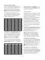
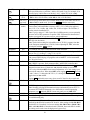
As you rotate the filter controls (shift, width, hicut,
locut), the associated parameter value is shown on
VFO B. The filter graphic shows the width and
location of the passband, as illustrated below. In
these specific examples, segments that turned off as
a result of control movement are shown in gray.
Also see Text Decode and Display (pg. 33) and
Audio Effects (pg. 35).
Receiver Gain Controls
High Cut
Use AF — SU B (pg. 11) to set the desired main
and sub receiver volume level. There are two
overall audio volume ranges, LO and HI, which can
be selected using CONFIG:AF GAIN.
Low Cut
Usually, both
RF — SU B controls will be set
fully clockwise (main and sub receiver RF gain).
You may wish to reduce RF gain to optimize
receiver response to high signal levels or noise.
Width
If the sub RF gain knob has been reconfigured
as squelch for both receivers, then the main RF gain
knob will control RF gain for both receivers. (See
CONFIG:SQ MAIN.)
Shift
To improve weak-signal reception, turn on the
preamp using P R E . In the presence of extremely
strong signals, you may wish to use the attenuator
(A T T ), or reduce the RF GAIN setting.
Filter passband controls don’t apply in FM
mode. SHIFT control granularity can be set to
either 10 or 50 Hz in CW and DATA modes; see
CONFIG:PB CTRL. In Sync AM mode (A M- S ),
SHIFT selects the upper or lower sideband.
Crystal Filter Selection
You can install as many as five crystal roofing
filters in the K3’s main receiver, and another five in
the sub receiver. For diversity receive, matched
main/sub receiver crystal filters should be used (pg.
38).
Each passband control has an integral switch. These
switches are used as follows:
Tapping the control alternates between the two
primary functions for that control, for example
HICUT and WIDTH. This is indicated by the
two LEDs above each control.
Bandwidths as narrow as 200 Hz and variablebandwidth filters are available, thanks to the K3’s
low first I.F. (intermediate frequency) of 8.215
MHz. See Appendix A for recommended crystal
filter bandwidths for each mode.
Holding a control activates its secondary
function, labeled below the control.
Tapping or rotating a control shows the present
setting. To see the settings of both knob functions
without changing them, just tap the control twice.
To select a crystal filter manually, tap X F I L . The
FL1 -FL5 icons show the current selection. This
sets the DSP passband to match the crystal filter,
and removes any passband shift or lowcut/hicut.
The secondary functions of the controls are N O R M
and I/ I I , described in the following sections.
The K3 will also select the most appropriate crystal
filters automatically as you adjust the
SHIF T ,
WIDT H ,
L O C U T , and
H I C U T controls.
23
Filter Presets (I/II)
Custom Settings (NORM1 and NORM2)
Each operating mode provides two ‘floating’ filter
presets, I and II, which store filter settings on a
per-VFO, per-mode basis (excluding FM). They are
updated continuously as you change filter settings.
(Fixed, per-mode ‘normal’ settings are also
available as explained below.)
In addition to the K3's standard "NORM" values,
you can save two of your own setups in each mode,
then recall them using the N O R M function. These
setups are referred to as NORM1 and NORM2.
To save a custom normalization setting:
You can alternate between the I and II settings by
holding I/ I I . This is especially useful when you’re
alternating between a wide and narrow setting
during contest or DX operation.
The I and II settings for VFOs A and B are
independent.
•
set up the filter passband as desired for the
current mode
•
hold N O R M until you see < - SA V - > (3
seconds)
•
rotate the knob slightly left or right to save it as
N O R M1 or N O R M2 .
(The arrows to the left and right of SA V are a
reminder that you can rotate the knob to get to the
two user-defined normalization settings.)
Filter Normalization (NORM)
Standard Settings
To recall, hold N O R M until you see < - N O R - >
(about 1/2 second), then rotate the knob left or right
to recall N O R M1 or N O R M2 .
To get quickly to a standard per-mode bandwidth
and reset any passband shift or cut, hold N O R M
(normalize). The normalized AF bandwidth is 400
Hz in CW and DATA modes, 2.7 or 2.8 kHz in SSB
modes, and 3.0 kHz for AM1.
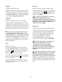
Narrow DSP Filter Types
For bandwidth settings of 100 Hz or lower, the K3’s
DSP normally uses a type of filter that minimizes
ringing: the Finite Impulse Response or FIR filter.
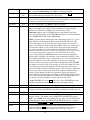
Whenever you normalize the filter passband,
two small "wings" appear at the left and right ends
of the DSP filter passband graphic as shown below.
If you’d like steeper filter skirts, and don’t mind a
small amount of ringing, you can select Infinite
Impulse Response” or IIR filters for these
bandwidths. Locate CONFIG:FLx BW menu entry,
then tap 7 until you see IIR O N . Both main and
sub receivers will use the same setting.
Moving any DSP control makes the "wings"
disappear, as a reminder that the passband is no
longer normalized.
IIR filters take longer to change from one
bandwidth to another, so you may hear audio
artifacts when adjusting the DSP controls. If this is
objectionable, use the default FIR filters.
1
In AM mode, the I.F. bandwidth required for
good fidelity is about twice the AF bandwidth.
This is why a 6 kHz or wider crystal filter is
needed to effectively use the 3 kHz NORM
setting. If a 15 kHz FM filter is installed, it can
be used in AM mode to provide good fidelity at
even higher AF bandwidth settings.
24
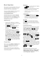
Reducing Interference and Noise
The DSP noise blanker is in the 2nd I.F., where
it can’t be activated by signals outside the crystal
filter passband. It can be used with high-duty-cycle
and complex-waveform noise generated by
computers, switching power supplies, light
dimmers, etc. The I.F. noise blanker is in the 1st
I.F., where it can use very narrow blanking widths.
It is most effective at blanking AC line noise,
lightning, and other very broadband noise. Often, a
combination of the two is the most effective.
The K3 provides several ways to cut interference,
including DSP noise reduction, manual and auto
notch, and noise blanking. Also see Audio Effects
( A F X , pg. 35).
There are actually two noise blankers: one at the
first I.F. (KNB3 module), and the other at the 2nd
I.F. (DSP).
Noise reduction, noise blanking, and notch
filtering should only be used when necessary. These
signal processing techniques are extremely
effective, but can introduce side effects. Sometimes,
reducing the filter bandwidth is the most effective
interference-reduction strategy.
Noise Reduction
Noise reduction reduces random background noise
while preserving meaningful signals. It adds a
characteristic “hollow” sound to all signals.
N R turns noise reduction on. It doesn’t apply to
DATA or FM modes, or with AGC turned off.
Noise Blanking
Hold A D J to display the NR setting, which is
saved per-mode. Use the VFO B knob to tailor NR
for the present band conditions. In general, the
higher the number, the more aggressive the noise
reduction. Settings F1 - 1 through F4 - 4 are
recommended. F5 - 1 through F8 - 4 use a different
algorithm, where the - x part of the setting indicates
the degree of mix between the DSP-processed and
unprocessed signals (- 1 is about 50% processed, - 4
is 100%). A small M appears to remind you that a
M ixed setting is in effect, e.g. N R M F5 - 1 .
First, tap N B to enable I.F. and/or DSP noise
blanking.
Next, hold L E V E L to set the DSP level (VFO A)
and I.F. level (VFO B). You’ll initially see D SP
O FF and IF O FF on the VFO A and B displays.
Rotating VFO A clockwise will turn on the DSP
NB, showing D SP t 1 - 1 through D SP t 3 - 7 . The
first number shows the relative pulse integration
time, and the second shows the blanking level. The
higher the numbers, the more aggressive the DSP
blanking action.
Notch Filtering
Rotating VFO B clockwise will turn on the IF NB,
showing IF N A R n , IF MED n , or IF W ID n ,
where n is 1 -7 . N A R /MED /W ID refers to narrow/
medium/wide blanking pulse widths, and n is the
blanking level. Higher n means more aggressive
blanking action. Use N A R width when possible to
minimize strong-signal interaction effects.
Notch filtering removes interfering carriers while
leaving the desired signal relatively unaffected. The
K3 provides automatic and manual notch tuning.
Auto notch will find and remove one carrier, and in
some cases more than one. (SSB mode only.)
Manual notch removes one carrier at a specified
pitch, and can be used in CW and DATA modes as
well as voice. Since manual notching sets up a fixed
(rather than adaptive) notch, it can even suppress a
keyed carrier, i.e. a Morse code signal.
The N B icon will flash slowly if the I.F.
blanker setting is too high for the present signal
conditions. If this happens, use a lower setting.
Both the DSP and IF blanking settings are saved on
a per-band basis. If CONFIG:NB SAVE is set to
YES , the on/off status of N B will be also be saved
for each band.
Tap N T C H to turn on notch filtering (N TC H icon).
This turns on Auto notch in SSB mode, and
Manual notch in other modes (adds
icon).
Holding M A N U A L directly selects manual notch in
any mode. Adjust the manual notch frequency using
VFO B, then tap N T C H again to exit.
25
Transmitter Setup
VOX, PTT, and QSK
Transmit Crystal Filter Considerations
In voice and data modes, use V O X to select VOX
(pg. 13) or PTT (push-to-talk). PTT can still be
used even with VOX selected. Set VOX gain and
anti-vox level using MAIN:VOX GN and
ANTIVOX.
For each operating mode, you must specify which
I.F. crystal filter to use for transmit using the
CONFIG:FLTX menu entry. See pg. 47 for
recommended per-mode transmit filter bandwidths.
In CW mode, use V O X to select either VOX or PTT
transmit. VOX enables “user-activated” (hit-thekey) transmit, while PTT requires the use of PTT
IN (pg. 17) or X M I T before CW can be sent.
Transmit signals are generated on the RF board,
so the set of filters installed on the RF board must
meet the transmit bandwidth requirements of all
modes you plan to use. (Filters installed on the sub
receiver board are used only in receive mode.)
When the VO X icon is on in CW mode, you can
use Q S K to select full (Q SK icon on) or semi
break-in. For more on break-in keying, see pg. 30.
Transmit Status LEDs and Icons
Transmit Metering
Before putting the K3 on the air, you should be
familiar with the LEDs and LCD icons that pertain
to transmit operation (identified on pgs. 11 and 12).
The most important of these are reviewed here.
Normally, the transmit bar graph shows SW R and
R F (power output). The displayed SW R range is
1:1 to 3:1. The R F control range is 0 to 12 W in
1-W units, or 0 to 110 W in 10-W units. The power
scale changes from watts x1 to watts x10 at 13
watts.
The TX LED turns on during transmit. The ∆F
(Delta-F) LED turns on if the transmit and receive
frequencies differ (SPLIT / RIT / XIT).
In voice modes, you can use M E T E R to switch to
compression (C MP ) and automatic level control
(A LC ) metering. See pg. 28 for information on
adjusting the
M I C and
C M P controls.
The TX LCD icon and associated arrows show
which VFO is being used for transmit. If you plan
to use S P L I T mode, See pg. 36.
If you have a KXV3 installed, you can use
milliwatt-level power output. This is intended for
use with transverters, but it can also allow the K3 to
act as a very stable, very low-noise signal generator.
To route RX and TX through the XVTR jacks on all
bands, set CONFIG:KXV3 to TES T .
Multifunction Transmit Controls
There are two multifunction transmit controls. Their
primary functions (mode-dependent) are:
SPEED
MIC
CMP
PWR
CW keyer speed in WPM
Mic gain
When milliwatt-level output is in effect, rotating
P W R will show milliwatts on VFO A, and dBm
(dB relative to 1 milliwatt) on VFO B. The RF bar
graph displays power output in tenths of a mW.
Speech compression level in dB
RF output power in watts (6 m and
transverter power settings are
independent of other bands; also see
Per-Band Power Control, pg. 27)
Off-Air Transmit Testing
The secondary (hold) functions of these controls
are:
DELAY
VOX or CW semi-break-in delay
MON
Voice/Data monitor or CW sidetone
level.
The K3 allows you to listen to your CW keying, test
your mic and compression settings, or monitor
DATA tones, without transmitting an on-air signal.
To do this, hold T E S T (right end of the M O D E
control). While you're in TEST mode, the TX icon
will flash slowly as a reminder that you're off air.
Hold T E S T again to return to normal operation.
26
External ALC
Per-Band Power Control
External ALC should only be used to protect
your amplifier during operation into a failed
load, or during a prolonged overdrive condition.
ALC should not be used as a way to clip or
compress fast voice peaks, or as a primary
means of amplifier or K3 power output control.
If the CONFIG:PWR SET menu parameter is set
to N O R , power output on all HF bands follows the
present setting of
P W R . (6 m and transverter
bands are always independent of HF.) If you change
PWR SET to PER - B A N D , the power level will
be saved independently on each HF band. This is
especially useful with external amplifiers, or for
those who use QRP levels on one band and QRO on
another.
DO NOT set the K3’s power level to
maximum and adjust amp output using the
amp’s ALC control. This will result in splatter
and key clicks. Instead, adjust the drive on each
band so it’s just below ALC activation level.
When per-band power control is used with an
external amplifier, you can adjust the drive ideally
on each band to prevent external ALC activation
during normal operation.
Preparing the K3 for use with External ALC
You may need to modify the K3 to use
external ALC, depending on its date of
manufacture. Please refer to our K3 Modifications
web page. If you turn on external ALC without
making necessary modifications, power will be
reduced to a very low level during transmit.
TUNE Power Level
If CONFIG:TUN PWR is set to N O R , power
output during T U N E will follow the present setting
of
P W R . If you change the TUN PWR
parameter to a fixed power level, that level will be
used during T U N E , whether or not you’ve selected
per-band power control (see above).
External ALC Setup
External ALC is set up using the CONFIG:EXT
ALC menu entry. EXT ALC defaults to O FF . To
turn it O N , tap 1 . 6 meter external ALC can be
turned on/off separately from HF.
Transmitter RF Delay
Some amplifiers have slow relays whose switching
time must be accommodated to prevent key clicks
during CW operation. If your amplifier requires
more than 8 ms of relay switching time, you can
increase the delay from key-down to RF output at
the K3 using CONFIG:TX DLY.
The EXT ALC menu entry provides a default ALC
threshold of - 4 . 0 V, used by many amplifiers.
If you select C MP /A LC metering at the K3,
external ALC activity is indicated by 8 or more
bars. If you select SW R /R F metering, the
C MP /A LC meter icons will flash during external
ALC activity to make you aware of the condition.
Use the smallest value of TX DLY that works
with your amplifier. Larger values will affect QSK
and keying timing at high code speeds.
Some experimentation may be required to
determine the proper setting of the amplifier’s ALC
output control, if one is provided. Start with the
control set for minimum ALC output. Then adjust
the K3’s power output such that the amplifier is just
reaching its maximum level on voice peaks (in SSB
mode) or peak CW power in CW mode.
Transmitter Inhibit
Some multi-transmitter stations require that
transmitters be able to mutually inhibit each other in
order to prevent simultaneous use of resources. The
K3’s transmit inhibit input (TX INH) can be set up
for low- or high-active control (pg. 19).
Next, adjust the amplifier’s ALC output control
upward until ALC action just begins (or adjust the
K3’s ALC threshold with the EXT ALC menu
entry). Finally, reduce the K3’s drive power just
slightly to provide some safety margin. The goal is
to have no amplifier ALC action during normal
operation. If you see an ALC indication at the K3 or
the amplifier, reduce the K3’s power output.
Fan Speed
The K3/100 includes two large, quiet fans. Fan
speeds are normally selected automatically, but you
can manually select a minimum fan speed if
desired. See the CONFIG:KPA3 menu entry.
27
Voice Modes (SSB, AM, FM)
Mic Gain and Compression Settings
Mode Selection
See pg. 75 for a general discussion about voicemode ALC. To set up mic gain and compression:
Tap either end of M O D E to select LSB /U SB ,
A M , or FM mode. Holding the left end of this
control, A L T , selects an alternate mode. LSB and
U SB are alternates of each other. The alternate for
A M is A M- S (synchronous AM, pg. 29). In FM
mode, A L T enables a repeater offset (pg. 29).
•
Set the monitor level as described earlier.
•
Optionally select TX TEST mode (pg. 13) or
set power to zero. This will not affect your
C MP /A LC bar graph readings.
•
Set
Microphone Selection
•
Hold M E T E R to select C MP /A LC metering.
The K3 provides both front- and rear-panel mic
jacks. Some operators use rear-panel jacks to
minimize clutter around the front panel. Use
MAIN:MIC SEL to select the front panel (FP ) or
rear-panel (R P ) jack, low or high mic gain range,
and bias voltage for electret microphones.
•
While speaking into the microphone in a
normal voice, adjust
M I C for a peak ALC
meter indication of about 5-7 bars (see below).
CMP
to 0 .
•
The front-panel mic jack is compatible with the
Elecraft MH2, MD2, Proset-K2, and some other 8pin mics (see pg. 13 for pinout and bias settings).
•
Adjust
C M P for the desired speech
compression level while speaking. The C MP
scale shows approximate compression level.
•
Hold M E T E R to select SW R /PW R metering.
•
If you were in TX TEST mode, return to
normal operation by holding T E S T .
Voice monitoring allows you to hear the way you’ll
sound on the air with your selected mic gain,
compression, and TX EQ settings. For voice
monitoring without any processing or delays, set
CONFIG:TX MON to FA S T .
•
If you had
P W R set to 0, set it for the
desired level. Key the rig again and verify that
you have about the right power output level.
To set up voice monitoring:
Power Level for Voice Modes
The rear-panel jack is 3.5 mm (1/8”). The rearpanel PTT IN jack can also be used if required.
Voice Monitoring
•
Hold T E S T to put the K3 in TX TEST mode,
so you won’t be transmitting (pg. 13).
•
Set
•
Press your mic’s PTT switch or tap X M I T .
•
While speaking into the mic, adjust M O N for
the desired level. (DVR playback level can be
set differently; see CONFIG:TX DVR).
MIC
You can LOCK the MIC, CMP, and PWR
settings if required; see CONFIG:PWR SET.
Voice power may be slightly different from the CW
power you see in when you use T U N E . Increasing
mic gain cannot correct for this. Instead, use the
CONFIG:TXG VCE menu entry (voice transmit
gain). A value of -1.5 to 1.5 dB should make voice
power about the same as when using T U N E .
high enough to hear your voice.
•
Exit transmit (release PTT, or tap X M I T again).
•
You can either leave the K3 in TX TEST mode
or go back to normal transmit (hold T E S T ) as
you follow the instructions in the next section.
If you’re using an external peak-reading
wattmeter, adjust power such that speech peaks
remain at or below your desired power level. The
K3’s RF bar graph may not capture all speech
peaks, but your actual output will be close to that
set with
PWR .
28
Voice Mode VOX Setup
Transmit Noise Gate
VOX
selects push-to-talk (PTT) or voice-operated
(VOX) transmit (VO X icon on). VOX hold time is
set with
D E L A Y (pg 14).
The noise gate function mutes mic audio below a
selected threshold; this may be useful in noisy
environments. See CONFIG:TX GATE for details.
MAIN:VOX GN (VOX gain) should be set to
trigger at normal speech level, but not in response
to incidental noise. Start with low settings (5-10).
AM Operation
A 6 kHz (AM) crystal filter is required for AM
transmit (pg. 47). AM receive is possible with any
filter from 2.7 to 13 kHz. 6 kHz is recommended.
MAIN:ANTIVOX sets VOX immunity to RX audio.
With the mic closer to the speaker than normal,
increase ANTIVOX until the K3 doesn’t switch to
TX mode when listening to a loud signal.
switches from envelope detection to sync
detection (A M- S ). Sync AM can improve copy
during selective fading. When A M- S is in effect,
rotating
S H I F T selects the upper or lower
sideband; one or the other may improve copy.
ALT
SSB/CW VFO Offset
The K3 can automatically offset the VFO frequency
when you switch from SSB to CW mode, so other
stations will hear the correct CW pitch. See
CONFIG:CW WGHT for details.
Digital Voice Recorder (DVR)
VFO A can automatically track AM signals in A MS mode. This can be useful when listening to
signals mistuned from a nominal frequency. Tap
S P O T to zero in on an AM signal one time; tap
C W T for full-time tracking (T icon turns on).
With the KDVR3 installed, you can record and play
voice messages as well as capture received audio.
Use S P L I T if you don’t want your transmit
frequency to change during auto-tracking.
Transmit Message Record and Playback
You can also listen to AM using LSB or USB
modes. A 2.7 or 2.8 kHz filter will work well.
Tap R E C to start recording, then tap any of M 1 M 4 . Remaining buffer time will be displayed as
you speak. Tap R E C again to end, or C L R to erase.
FM Operation
Tap M 1 – M 4 to play. To cancel, tap R E C . If
you wish to manually assert PTT when using the
DVR, see CONFIG:KDVR3. MIC gain has no
effect during message play; the gain setting at
record time is used. However, DVR monitor level
can be set separately (see CONFIG:TX DVR).
An FM crystal filter (at FL1) is required on the RF
board and/or sub receiver for FM use; see pg. 46.
To auto-repeat, hold (rather than tap) M 1 – M 4 .
MAIN:MSG RPT sets the interval (1-255 seconds).
•
Hold A L T to select simplex, TX up (+ icon), or
TX down (- icon). If an offset is in effect, R E V
swaps RX/TX frequencies and offset direction.
•
Set up repeater offsets with MAIN:RPT OFS,
and VFO step size using CONFIG:VFO CRS.
•
Hold P I T C H to set up tone encode. VFO A
selects pitch in Hz; VFO B turns tone encode
on or off. If 1 7 5 0 Hz is selected (for European
repeaters), an 0.5-s tone burst is sent at the start
of each transmission if squelch wasn’t already
open. Or, you can hold P I T C H during TX to
manually generate a tone burst of any length.
•
To see up voice and PL tone deviation, use
CONFIG:FM DEV.
FM mode can be disabled by setting
CONFIG:FM MODE to O FF .
To setup for repeater use:
Hold R E C to select bank 1 or 2 (4 messages each).
Receive Audio Record and Playback
Hold A F R E C to start/stop record. The
icon
will flash slowly while recording. Only the last 90
seconds of audio will be available for playback.
Hold A F P L A Y to start/stop play. The
icon
will flash quickly during play. A seconds counter
will be displayed on VFO B, along with an asterisk
(*) if you’re within the most recent segment.
Rotating VFO B adjusts the playback position.
29
CW Mode
SPOT and Auto-Spot
CW Normal and Reverse
When calling another station, you should try to
match your frequency to theirs. To facilitate this,
the K3 provides both manual and automatic
spotting for use with CW and DATA signals. See
Tuning Aids: CWT and SPOT (pg. 34).
Select CW mode by tapping either end of M O D E .
Hold A L T to alternate between CW normal (lower
sideband RX) and reverse (upper sideband RX).
CW Text Decode/Display
If you S P O T (or auto-spot) a CW signal (pg. 34),
then switch between CW normal and reverse, the
pitch of the received signal should stay the same.
The K3 can decode transmitted and received CW
signals, displaying the text on VFO B (pg. 33). This
is especially useful when you’re learning CW, or if
someone who doesn’t know CW is looking over
your shoulder while you make CW QSOs. It’s also
indispensable for CW-to-DATA operation (pg. 34).
Basic CW-Mode Controls
In CW mode,
MON
sets the sidetone volume.
Hold P I T C H to adjust the sidetone pitch. The peak
in response of all filters will track this setting.
APF and Dual Passband CW (DUAL PB)
Use A G C to select slow AGC (A G C - S ) or fast
(A G C - F ). Slow is fine for casual operating; fast is
useful during contests or rapid signal fading.
In CW mode, D U A L P B turns on either a narrow
audio peaking filter (APF) or dual-passband CW
(Dual PB). See pg. 35.
Hold Q S K to select full break-in (Q SK icon on) or
semi break-in operation. Q SK allows others to
“break” your CW transmission by sending one or
two characters. With semi break-in selected (Q SK
off), the K3 returns to receive mode after a time
delay you set using D E L A Y .
CW Message Record/Play
Messages can only be recorded using the
internal keyer or the message editor in K3 Utility,
not by using a hand key or external keyer.
must be turned on in CW mode to enable
both full and semi break-in operation. If PTT is
selected (VO X icon off), transmit must be activated
using PTT or by tapping X M I T . PTT is sometimes
activated using a foot switch.
If text decode is on (pg. 33), CW text sent
using the internal keyer is shown on VFO B (pg.
33). Use T E S T to check messages off-air (pg. 13).
For ultra-fast CW full break-in at up to 100
WPM, set CONFIG:CW QRQ to O N . If CW
QRQ is O FF , max speed using VOX is 60 WPM,
and PTT is required for 60 to 100 WPM.
Message Record: To start recording, tap R E C ,
then M 1 - M 4 . The remaining buffer space will be
displayed as you send. Tap R E C again to stop.
VOX
There are 8 message buffers (2 banks of 4). Each
holds 250 characters. To switch banks, hold R E C .
Message Play: Tap M 1 – M 4 to play. To cancel,
tap R E C or hit the keyer paddle or key.
Hold T E S T to place the K3 into TEST mode. This
sets power output to zero, useful for CW practice or
for off-the-air checking of recorded CW messages.
Message Erase: Tap R E C , then M 1 – M 4 , then
CLR .
Other CW-Mode Configuration Settings
Auto-Repeat: To auto-repeat a message, Hold
(rather than tap) M 1 – M 4 . MAIN:MSG RPT sets
the message repeat interval (1 to 255 seconds).
Use the CONFIG menu to set up iambic keying
(CW IAMB), paddle norm/reverse (CW PADL),
and keying weight (CW WGHT). The CW WGHT
menu entry can also be used to enable automatic
SSB/CW VFO offset (pg. 29).
Chaining: Tapping M 1 – M 4 during playback
chains another message onto the message being
played. Holding a message switch during playback
chains a repeating message.
30
Data Modes
The following data modes are available:
You don’t need a computer to get started with data
modes on the K3: it can receive and display RTTY
and PSK31 on its LCD (pg. 33). You can transmit
in data modes using your keyer paddle (see CW-toDATA, pg. 34).
•
D A T A A can be used for all A udio-shift
•
A FS K A also uses A udio-shift transmit, but is
•
FSK D is identical to AFSK A, except that
D irect modulation is used, via FSK IN, ASCII,
Using a computer for data modes is also very
convenient on the K3, as described below. If you’re
using AMTOR or PacTOR, also see pg. 32.
Data Mode Connections
You can transmit and receive data with a computer
in three ways:
•
Connect your soundcard I/O to the K3. Use
MAIN:MIC SEL to use LINE IN/OUT, frontpanel mic jack, or rear-panel mic jack. You can
use VOX or PTT to control transmit.
•
Use the soundcard in receive mode, but use a
PC I/O line to do direct FSK (or PSK)
modulation. Connect the PC’s I/O line to the
“FSK IN” line on the K3’s ACC connector. (If
this signal originates from an RS232 port, it
will require RS232-to-TTL level conversion.)
•
Send and receive ASCII text via the RS232
interface. To send, insert text into a “KY”
command (e.g., “KY CQ DE N6KR;”). To
receive, send “TT1;” (text-to-terminal). “TT0;”
turns it off. See the K3 Programmer’s
Reference, available at www.elecraft.com.
transmit modes, including PSK31, MFSK,
AFSK, etc. The VFO displays the suppressedcarrier frequency, just as when SSB modes are
used for data. USB is “normal” for DATA A.
Compression is automatically set to 0.
optimized for RTTY. The VFO displays the
RTTY mark frequency, and LSB is “normal”.
The built-in text decoder can be used in this
mode (pg. 33), as well as the dual-tone RTTY
filter (DTF, pg. 32).
or the keyer paddle (pg. 34). The text decoder
can be used in this mode (pg. 33), as well as the
dual-tone RTTY filter (DTF, pg. 32).
•
PSK D is a D irect-transmit mode for PSK31.
It’s the only mode that decodes and displays
PSK31 signals with the text decoder (pg. 33).
Like FSK D, PSK D lets you transmit via
FSK IN, ASCII, or the keyer paddle (pg. 34).
You can also use auto-spot with PSK D if the
tuning aid is displayed ( C W T , pg. 34).
The D A T A M D display also shows the data speed in
bps on VFO A. This is relevant only if the text
decoder is on. Depending on the mode, other data
speeds may be available; select them by rotating
VFO A.
Also shown is the current sideband (LSB or U SB ).
If this sideband is considered “data reverse” for the
present mode, then R E V also appears. You can use
A L T to switch to the other sideband if required.
R EV is not recommended with CW-to-DATA (pg.
34).
Data Mode Selection
Soundcard-based data communications can be done
using LSB or USB mode. However, DATA modes
offer several benefits not available in SSB modes.
If you prefer to use LSB or USB, you’ll need to
manually set
C M P to 0 to prevent data signal
distortion. Refer to your data communications
software manual to determine how to set up the
VFO and computer for accurate frequency display.
Mark/Shift and Pitch Selection (PITCH)
Hold P I T C H to view and change the received mark
tone and shift (AFSK/FSK) or center pitch (PSK).
In AFSK/FSK modes, you have a choice of mark
tone/shift combinations. Use VFO A to select a
tone/shift combination that’s compatible with your
software. A lower mark pitch makes signal tuning
easier when using the K3’s text decoder.
To use DATA modes, tap M O D E until the D A T A
icon appears. Next, hold D A T A M D . The present
data mode is shown on VFO B, and can be changed
by rotating the VFO B knob.
31
RTTY Dual-Tone Filter (DTF)
AMTOR / PacTOR
Hold D U A L P B to turn on the RTTY dual-tone
filter (DTF). This creates two filters, one centered
on the mark tone, the other on space, which can
often improve RTTY copy. The filter graphic
changes to reflect this (see below).
AMTOR, PacTOR and similar modes can reliably
transfer data – including e-mail – via HF radio
networks. New modes are under development that
may provide even greater reliability. Applications
include maritime mobile and emergency
communications where the K3’s light weight and
excellent receive performance are advantageous.
General information regarding K3 set up for these
modes appears below.
When DTF is on, the range of the
WIDT H
control is adjusted to better match the
characteristics of the filter. SHIFT, LOCUT and
HICUT are disabled.
•
Frequency stability is important in these modes.
A 1-PPM TCXO is available (KTCXO3-1).
•
Connect modem audio I/O to the K3’s LINE
OUT and LINE IN jacks (for LINE OUT, use
the TIP contact of a stereo plug). A PTT
connection is also usually required. If the
modem operates from 12 V (0.5 A or less), it
can be powered from the K3’s 12 VDC output.
•
Set up the modem (if applicable). Settings may
vary depending on the data mode being used.
•
Locate CONFIG:LIN OUT and set it to 10. A
different level may be better for your modem.
•
The K3’s SYNC DATA feature can be used to
minimize T-R delays (it forces the same crystal
filter to be used for both receive and transmit).
Locate CONFIG:SYNC DT. Assign it to a
programmable function (e.g., by holding P F 1 ),
then exit the menu.
•
Tap M O D E to select D A T A .
•
Select an appropriate data sub-mode by holding
D A T A M D , then rotating VFO B. D A T A A
(generic data mode, USB) is used in most cases;
see pg. 31 for alternatives, such as A FS K A .
Tap A F X to exit the parameter display.
•
Locate MAIN:MIC SEL and set the audio
source for data to LIN E IN . Exit the menu.
•
If you wish to use SYNC DATA, turn it on by
holding P F 1 (or the switch used above). The
– S icon will appear. A CONFIG:PTT RLS
value of 10 to 12 may be ideal in this case.
•
Some modes may have very high duty cycles;
use less than full power output if required.
The dual-tone filter can be used with A FS K A and
FSK D . The on/off state of DTF is saved
independently for each of these modes.
FSK Transmit Polarity
You can invert the logic level of the FSK IN line in
FSK D mode using CONFIG:FSK POL. This
should be used only with external keying via
computer programs such as MMTTY; it is not
recommended for use with CW-to-DATA (pg. 34).
Mic Gain, ALC, and Monitor Level
If you’re using an audio-shift transmit mode (LSB ,
U SB , D A T A A , or A FS K A ), you’ll need to set
the
M I C level while watching the ALC meter.
You can use the same procedure outlined for voice
modes (pg. 28), except that speech compression
should not be used.
In all cases (SSB modes as well as DATA), you can
optionally use M O N to monitor your data
signals. The procedure given for voice modes can
be used (pg. 28). Voice-mode and DATA-mode
monitor levels are independent.
The
M I C setting does not apply to direct
modulation data modes (FSK D and PSK D ),
since no audio is used for transmission. However,
you can still use M O N to monitor the signals.
Refer to your application software for instructions
regarding email set up and other operating details.
32
Advanced Operating Features
Text Decode And Display
DATA Text Decode Setup
The K3 can decode CW, PSK31 and RTTY.
Decoded text is displayed on VFO B. In data
modes, you can use the K3’s internal keyer to
transmit PSK31 and RTTY signals (pg. 34).
To set up text decode for DATA modes:
When text decode is enabled, rotating the
RIT/XIT offset control doesn’t display the offset.
•
Set M O D E to DATA. Then hold D A T A M D
and select either A FS K A , FSK D , or PSK D
mode using VFO B. Tap A F X to exit the datamode display.
•
For A FS K A or FSK D , hold P I T C H and
select the desired mark/shift setting. The lowest
mark tone selection (915 Hz) may be more
pleasant to listen to than higher tones. (The
pitch for PSK D mode is fixed at 1010 Hz.)
Tap S P O T to exit the pitch display.
•
Hold T E X T D E C , then select O N using VFO
B. Below the D A T A icon you should now see a
T, showing that text decode is enabled.
•
Adjust the threshold (TH R ) using VFO A. Start
with TH R 0 . Higher settings prevent text
decode on weak signals or noise. Tap C W T to
exit text-decode setup.
•
You’ll probably want to turn on C W T as a
tuning aid (pg. 34). This also enables auto-spot
(applicable to PSK31 but not RTTY).
CW Text Decode Setup
To set up CW text decode:
•
Set M O D E to CW.
•
If a special VFO B display mode is in effect,
cancel it by tapping D I S P .
•
Hold T E X T D E C , then select C W 5 - 4 0
(lower WPM range) using VFO B. Below the
C W icon you’ll see a T (text decode enabled).
The TX O N LY setting decodes only CW you
send (internal keyer), so the T does not appear.
•
Adjust the threshold (TH R ) using VFO A. Try
A U T O or 1 - 6 (also see tips below). Tap C W T
to exit text-decode setup.
•
You’ll probably want to turn on C W T as a
tuning aid (pg. 34). This also enables auto-spot.
DATA Mode Text Decode Tips:
CW Text Decode Tips:
•
S P O T (or auto-spot) a signal first, then tune
slowly until recognizable words appear.
•
Noise or fading may result in invalid character
decodes, causing asterisks (* ) to appear. In
difficult conditions, reduce
W I D T H to as
low as 50 Hz (100-200 Hz for faster CW).
•
•
To optimize text decode, use manual threshold
settings. Start with TH R 5 . With C W T on,
adjust the threshold so that the C W T bar
flashes in sync with the received CW signal.
To decode very fast CW, use C W 3 0 - 9 0 .
Received CW Speed Display:
Received CW speed (from about 10-70 WPM) can
be displayed using the W PM C H K setting. The left
end of the display shows WPM, e.g. 2 0 w C Q D X .
33
•
Use F I N E tuning with PSK D . S P O T (or
auto-spot) a signal first, then tune slowly in 1Hz steps until recognizable words appear.
•
If you call CQ using PSK31 mode, keep RIT on
so you can fine-tune responding stations
without moving your transmit frequency.
•
In difficult conditions, reduce
W I D T H to
the per-mode minimum (typically 50 Hz for
PSK31, 200 Hz for narrow-shift RTTY).
•
In A FS K A and FSK A modes, the RTTY
dual-tone filter may help (DTF, pg. 32).
•
RTTY text may shift to figures due to noise.
If you assign CONFIG:TTY LTR to a
programmable function switch, you can tap it
to quickly shift back to letters.
CW-to-DATA
Tuning Aids: CWT and SPOT
You can use data modes completely stand-alone
(i.e., without a computer). Just turn on text decode
(pg. 33), and send CW using the internal keyer.
Tapping C W T turns the upper half of the S-meter
into a CW/DATA tuning aid. If no bar appears in
the tuning area, the threshold may be set too high;
hold T E X T D E C and select a lower TH R value.
When a received CW or PSK31 signal is centered
in the passband, the CWT display will appear as
shown below.
CW messages can also be used for CW-to-DATA.
This makes it easy to answer a CQ, send a contest
exchange, or play a “brag tape” during a QSO.
To set up for CW-to-DATA operation:
•
CWT
Referring to pg. 33, use M O D E , D A T A M D ,
T E X T D E C , and P I T C H to set up text decode.
Select either FSK D or PSK D mode. A small
T should appear below the D A T A icon.
•
Try tuning in a few stations (turn on C W T ; pg.
34). Tips for improved copy in tough band
conditions are provided on pg. 33.
•
Plug a keyer into the PADDLE jack. The first
time you try CW-to-DATA, set
P W R to 0
watts or use TX T E S T mode (pg. 13).
•
All CW you send will be transmitted as data
and displayed on VFO B. You’ll hear a CW
sidetone, as well as PSK or FSK tones. Adjust
the data monitor volume using M O N . To
adjust the CW sidetone monitor level,
temporarily switch back to CW mode.
•
When calling CQ, use RIT to tune in stations
that reply (especially important for PSK D ).
•
Whenever you pause, the K3 will remain in a
data idle state for about 4 seconds before
dropping. To extend the timeout, send BT,
which is not transmitted as data.
•
To cut the idle transmit period and exit to
receive mode, send ". . - - " (IMmediately exit).
This character is not transmitted as data.
•
When recording CW messages for use during
CW-to-DATA, you can add ". . - - " at the end to
cut the idle time when they’re played back.
S1 3 5 7 9
SWR
2 3
RF
50
100
In RTTY modes (A FS K A and FSK D ), mark and
space tones are represented by three bars each, with
mark to the left of the CWT pointer, and space to
the right. When only weak signals are present in the
mark/space filters, 1-3 bars will flicker on either
side, leading to a “ghosting” effect, as shown here.
CWT
S1 3 5 7 9
SWR
2 3
RF
50
100
As you tune the VFO close to an RTTY signal, the
number of bars will initially increase on one side or
the other. Keep tuning until you see a rough balance
between left and right bars. (Also see DTF, pg. 32,
and CONFIG:TTY LTR.)
Manual SPOT
If C W T is off, you can tap S P O T , then manually
tune the VFO until the received signal’s pitch
matches the sidetone. If you find pitch matching
difficult to do, try auto-SPOT (below).
Auto-SPOT
To use auto-spot, first turn on C W T . Use a narrow
bandwidth (200 to 500 Hz). Tapping S P O T will
then automatically tune in a received signal that
falls within the CWT display range.
The CW abbreviation for “and” (ES) is not used
in data modes and might lead to confusion. Other
prosigns can be used, including KN, SK, and AR.
Auto-spot may not be usable if more than one
signal is in the CWT range, if the signal is
extremely weak, or if the code speed is very slow.
If you set VFO B for CW mode rather than
DATA mode and use cross-mode S P L I T (pg. 36),
your CW will not be converted to DATA.
Auto-spot coarse-tunes PSK31 signals, but you’ll
need to fine-tune them in 1-Hz steps (F I N E ).
34
Audio Effects (AFX)
Receive Audio Equalization (EQ)
If you have stereo headphones or stereo external
speakers, you can take advantage of the K3’s DSP
audio effects. These create an illusion of greater
acoustic space. For many operators, AFX provides
a less-fatiguing receiver sound.
The K3 provides 8 bands of receive audio
equalization via the MAIN:RX EQ menu entry. RX
EQ can compensate for the physical acoustics of
your station (room, headphones, speakers, etc.), or
just to tailor the audio to your personal preference.
Two receive EQ setups are provided: one for CW
mode, and the other for voice modes. RX EQ does
not apply to DATA modes.
MAIN:AFX MD is used to select the desired AFX
setting. Available selections include D EL A Y 1 -5
(quasi-stereo), and B IN , which provides a constant
phase shift between the left and right outputs.
In the RX EQ menu entry, the VFO A display
shows 8 individual vertical bar graphs. The example
below shows various amounts of EQ for each band.
Tap A F X to turn the selected effect on or off. This
can be done even within the AFX MD menu entry.
When the sub receiver is on, turning AFX on
may not have any noticeable effect. This is because
main/sub dual receive is already in stereo, with
different material routed to each audio channel.
USB
A
VOX
AGC-S
ANT 2
ATU
PRE
XFIL
NB
RIT
TX
B
FL2
APF and Dual-Passband CW Filtering
In CW mode, D U A L P B is used to turn on either
an Audio Peaking Filter (APF) or Dual-Passband
Filtering. Both are described below. CONFIG:
DUAL PB selects the desired function.
The center frequencies of the 8 audio EQ bands are
50, 100, 200, 400, 800, 1600, 2400, and 3200 Hz.
To select a band to change, tap 1 - 8 on the keypad.
For example, tapping 1 selects the 50-Hz band.
APF can make a dramatic difference in copy of
weak signals buried in noise. When APF is turned
on,
S H I F T fine-tunes the center pitch, and
N O R M resets the pitch to that of your sidetone. The
filter graphic will be similar to that shown below.
Next, rotate VFO A to specify boost or cut (+/- 16
dB). The illustration above shows the 800 Hz EQ
band (0 .8 0 kHz) being set to +1 dB of boost.
You can tap C L R to reset all of the RX EQ bands
to 0 dB (no cut or boost).
Transmit Audio Equalization (EQ)
Transmit audio equalization can compensate for
microphones and voice variations. MAIN:TX EQ
works exactly the same as RX EQ, and can be used
during transmit.
Dual-Passband Filtering (Dual PB) sets up a 150Hz-wide focus filter, set within a wider context
bandwidth that is attenuated by about 20 dB. This
lets you hear off-frequency CW signals, which may
be useful if you’re calling CQ, running a net, etc.
W I D T H varies the width of the context filter.
The filter graphic appears as above.
Hold D U A L P B again to exit APF or Dual PB.
Two transmit EQ setups are provide: one for SSB,
the other for wideband voice modes (ESSB, AM,
FM). TX EQ is not applicable to CW or DATA
modes.
When using either APF or Dual PB, you should
reduce the
W I D T H setting if there are S9+20 or
higher signals within the crystal filter passband.
This will maintain optimal AGC performance.
While adjusting TX EQ, you can monitor using
headphones (use M O N to set the level), or listen
to your transmitted signal on another receiver.
35
SPLIT and Cross-Mode Operation
General-Coverage Receive
Normally, VFO A is used for both receive and
transmit. When S P L I T mode is selected, VFO B
becomes the transmit VFO. In this case the SPL T
icon turns on, the TX arrow points to B (pg. 12)
and the yellow delta-F LED (∆f ) turns on if receive
and transmit frequencies or modes differ.
The KBPF3 option module includes band-pass
filters that cover the areas between ham bands. The
K3 will switch between its narrow ham-band filters
and the KBPF3 filters as you tune the VFOs.
A KBPF3 module can be installed on the RF board
(main receiver) and/or KRX3 (sub receiver).
Cross-mode operation is possible in some cases,
such as SSB/CW. You can use B S E T to directly
change the mode of VFO B (pg. 22).
CONFIG:VFO CRS selects C O A R S E VFO tuning
rate in each mode. AM coarse tuning rates include
5, 9, and 10 kHz.
You can transmit in CW when SSB mode is
selected by just hitting the key or paddle; there’s no
need to use cross-mode split in this case. The SSB
station will hear the signal at your sidetone pitch.
See CONFIG:CW WGHT.
Sensitivity below 1.8 MHz will be reduced due
to the high-pass response of the T-R switch, which
protects the PIN diodes.
VFO B Alternate Displays
Extended Single Sideband (ESSB)
The VFO B display can show time, date, RIT/XIT
offset, supply voltage, current drain, KPA3 heatsink
temperature (PA), and front panel temperature (FP).
Tap D I S P to turn the selected display on or off.
Rotate VFO B to select the desired display.
An increase in SSB voice bandwidth may improve
fidelity and reduce listening fatigue.
The K3’s normal SSB receive bandwidth is about
2.7-2.8 kHz. If you have a 6 kHz filter installed,
you can use
W I D T H to select a wider passband.
If CONFIG:TECH MD is O N , additional VFO B
alternate displays will be available. PLL 1 and
PLL 2 show the main and sub synthesizer PLL
voltages; if either is out of range, (*) will appear.
A FV shows the true RMS value of receiver AF
output (mVp-p), unaffected by AF GAIN control.
After the AFV reading stabilizes, you can use VFO
B to select dB V , which is useful for comparative
signal strength measurements. Also see
CONFIG:AFV TIM.
ESSB transmit is set up as follows:
•
A 6-kHz filter on the RF board is required.
Set this filter’s bandwidth to exactly 6 .0 0 kHz
(CONFIG:FLx BW). It must also be enabled
for AM transmit (switch to AM mode, then use
FLTX AM to specify the filter number).
•
Switch back to SSB mode. Locate
CONFIG:TX ESSB, tap 1 to turn ESSB on,
and use VFO A to select the desired transmit
bandwidth. The + icon will turn on in the mode
area of the LCD. See cautions below.
•
•
A FV and dB V apply to the sub receiver if it is
turned on. In this case, you may want to select
diversity mode (pg. 38) so you can tune the sub
receiver’s frequency with VFO A.
ESSB, AM and FM have separate TX EQ from
regular SSB, allowing you to optimize the
transmit passband for these wider-bandwidth
modes. See MAIN:TX EQ.
Alarm and Auto Power-On
Once you’ve set the K3’s real-time clock
(CONFIG:TIME), you can use MAIN:ALARM to
set an alarm. This can be used to remind you of a
schedule or net, or to start warming up for a contest.
Assign TX ESSB to a programmable function
switch if you’ll be turning it on/off frequently.
Carrier and spurious signal suppression,
passband shape, delay characteristics, fidelity,
and other aspects of ESSB performance are not
specified. Use ESSB only after carefully
monitoring your signal.
When an alarm is set, (*) appears in the time
display. (Time can be displayed by tapping D I S P .)
The K3 will turn ON automatically if it was off
at alarm time. It will be on the last-used band.
36
Using the Sub Receiver
The sub receiver’s band cannot be set
independently unless CONFIG:VFO IND is set
to YES . If it’s set to N O , you’ll see =MA IN
when you tap B A N D during B SE T , and the sub
receiver band will always be set the same as
main.
The KRX3 option adds an independent, highperformance sub receiver to the K3. It allows you
to monitor a second frequency, using different
bandwidths or modes. Diversity receive is possible
if the main and sub receivers use different antennas.
Sub Receiver Antenna Selection
Dedicated Sub Receiver Controls
The sub receiver gets its RF input either from the
main receiver (sharing ANT 1-2 or RX ANT IN), or
from its auxiliary antenna input (see pg. 41).
Tapping S U B turns on the sub receiver (and SU B
icon). VFO B then controls the sub’s frequency, and
also serves as the TX frequency during SPLIT.
When using B SE T , you can tap A N T to switch the
sub between MA I N (shared) and A U X (the sub’s
AUX input). When MA I N is in effect, the 1 -2 and
R X icons show which antenna the sub is sharing
with the main receiver. When A U X is in effect,
these icons will all be off (if CONFIG:KRX3 is set
for A N T =B N C ) or will show the non-transmit
ATU antenna, 1 or 2 (if KRX3 is set for
A N T =A TU ).
You should leave the sub off when not in use.
This turns off the -3 dB passive splitter used when
the sub shares the main receiver’s antenna path.
Holding S U B links the VFOs (whether the sub
receiver is on or off). The kHz decimal point of
VFO B flashes as a reminder. VFO A is the master,
moving both VFOs in tandem.
Holding S U B for 2 seconds or longer turns on
diversity receive (pg. 38). The kHz decimal point of
VFO A flashes as a reminder. VFO A controls both
the main and sub frequencies in diversity receive,
but VFO B remains independent so it can be used as
the SPLIT transmit frequency.
Shortcut: If you’re not in B SE T mode, you can
quickly switch the sub between MA I N and A U X by
holding R X A N T . (Tapping R X A N T turns RX
ANT on/off for the main path.)
The sub receiver’s AUX antenna must be
well-isolated from the transmit antenna to avoid
activating the sub’s carrier-operated relay.
SUB AF gain normally sets the sub’s volume
level. Alternatively, SUB AF can be used as a
main/sub balance control (see CONFIG:SUB
AF). With stereo headphones or dual speakers,
you'll normally hear main on the left and sub on the
right. CONFIG:L-MIX-R selects various alternate
combinations of main/sub audio mixing.
Using the AUX input for the sub receiver
slightly improves sensitivity of both the main and
sub receivers because the splitter is not used.
Sub Receiver Band Independence
CONFIG:SPKRS must be set to 2 if you use
stereo speakers; otherwise, set it to 1 .
If CONFIG:VFO IND is set to YES , you can set
the sub receiver to a different band from main.
Hold B S E T , then tap B A N D up/down to select the
sub receiver’s band. If you only use bandindependence for the sub occasionally, you may
want to assign VFO IND to a programmable
function switch (pg. 21).
SUB RF gain normally sets the sub receiver’s
RF GAIN level. If this knob is assigned to main/sub
squelch (CONFIG:SQ MAIN), then RF gain for
main/sub is controlled by the main RF gain control.
BSET: Additional Sub Receiver Settings
If the two receivers are sharing the main
antenna path, putting the sub receiver on a
higher-frequency band than main may result in
signal loss in the sub. This is due to sharing of the
main receiver’s low-pass filters. If you select an
incompatible band combination, the K3 briefly
displays U SE A U X as a warning. To avoid sub
receiver signal loss, use the sub’s AUX input.
Normally, receive controls apply only to the main
receiver. This includes SHIFT, WIDTH, P R E ,
A T T N , etc., as well as M O D E . To change these
settings for the sub receiver, first hold B S E T . VFO
A will show B SE T , and the S-meter will show the
sub receiver's signal level. After you’ve made the
desired sub receiver changes, tap A / B or hold
B S E T to exit B SE T .
37
Diversity Receive
Sub Receiver Crystal Filter Considerations
Diversity receive can greatly improve signal copy
during fading (QSB). True diversity requires a pair
of identical receivers running from a common
frequency reference and using two different
antennas. The K3 is one of very few transceivers
that offer this capability. Most offer only a lowperformance sub receiver, or “dual watch” (splitI.F.) circuitry, which doesn’t provide for separate
main/sub antennas.
Like the main receiver, the sub has slots for up to
five crystal filters. For best dynamic range, we
strongly recommend the use of the narrowest filter
consistent with each operating mode. CW and
DATA operators should have at least one narrow
filter, e.g. 400 or 500 Hz, on each receiver.
For diversity receive, we recommend using
identical crystal filter configurations for the two
receivers. This will ensure that both receivers have
the same characteristics when strong QRM is
present.
An antenna with different polarization, or at least
different orientation, should be used for the sub
receiver (via its AUX input). This ensures that the
two receivers will not experience the same fading
characteristics.
You should also use crystal filters with closely
matched offsets (CONFIG:FLx FRQ). Otherwise,
you may hear a slow phase modulation (similar to a
beat note) between the two receivers on some
signals. 8-pole filters are already matched (FLx
FRQ = 0.00). Elecraft can provide pairs of 5-pole
crystal filters with offsets within 40 Hz of each
other on request. When setting up FLx FRQ, use
the average of the filters’ marked offsets as the
value entered for both filters (main and sub). If you
enter different offsets, you’ll hear phase
modulation, even if the offsets are very close.
To turn on diversity mode: Hold S U B for 2
seconds or longer. This sets the sub to the same
frequency as main (VFO A), matches the sub’s
filter bandwidth to main, and switches the sub
receiver to its AUX antenna. The kHz decimal point
of the VFO A display flashes as a reminder. VFO A
sets the receive frequency for both main and sub in
diversity mode. This leaves VFO B free for use as
the transmit frequency in SPLIT mode (see details
at right).
SPLIT Mode with the Sub Receiver
Mode and filtering changes made to the main
receiver will immediately be made at the sub, as
well, to preserve diversity characteristics. However,
P R E , A T T N and other receive controls remain
independent for the sub. These must be changed
using B S E T .
With the sub receiver installed, in a sense all
operation is “split,” since you listen on the sub’s
frequency (VFO B) and listen/transmit on the main
RX/TX frequency (VFO A). Cross-mode and even
cross-band operation is possible in this case. Crossband operation may require the use of the sub’s
AUX antenna source to avoid the low-pass filter
problem described on the previous page.
You can change the sub receiver’s antenna selection
by holding B S E T , then tapping A N T . When you’re
not using BSET, holding R X A N T will accomplish
the same thing, providing a convenient shortcut.
If you do turn on S P L I T , the VFO’s roles are
reversed, with VFO B controlling the transmit
frequency, and VFO A used only for receive. The
advantage of this is that the receive controls are
always “visible” for VFO A, while receive controls
for VFO B must be accessed using B S E T .
The K3 saves the sub’s MAIN/AUX selection
independently for diversity and non-diversity. AUX
should be used for diversity, as explained above.
You might use MAIN with diversity when
comparing main/sub receiver gain, such as when
adjusting crystal filter gain compensation
(CONFIG:FLx GN). The built-in true-RMS
voltmeter is ideal for this purpose. Entering
diversity mode will allow you to tune both receivers
with VFO A, while VFO B displays the voltage (see
AFV/dBV, pg. 36).
Diversity with SPLIT: In diversity mode you can
still use SPLIT, but both receivers will be set to the
frequency of VFO A. Both receivers will always be
in the same mode, and will use the same filter
settings.
38
Receive Antenna In/Out
Using Transverters
The RX ANT IN/OUT jacks, supplied with the
KXV3 option, have various uses:
Nine user-definable bands are provided for use with
transverters. These can be used with the Elecraft
K144XV internal 2-m module, Elecraft XV-Series,
or other transverters. See pg. 18 for connections.
•
•
•
•
Low-noise receiving antenna: Some operators
use a Beverage, tuned loop, or other low-noise
receiving antenna. You can connect such
antenna to the RX ANT IN jack, then tap
R X A N T to select it. The R X icon will turn on.
Transverter Band Setup
Transverter bands are set up using the XV menu
entries. Tap 1 – 9 within menu entries to select a
transverter band to configure.
Narrowband filters or preamps: You can
"patch in" a specialized filter or preamp (e.g.,
the Elecraft PR6 preamp for 6 meters) between
RX ANT IN / OUT. Tap R X A N T to switch the
filter in (per-band). It will be in-line only during
receive, so you can use low-power devices.
Test signal injection: The RX ANT IN jack is
ideal to inject a test signal, because the
generator won't be damaged if you transmit.
Receiver comparisons: If you connect the RX
ANT OUT jack to a second receiver, and leave
the RX ANT IN jack open, you can A/B test the
K3 against the other receiver. When the R X
A N T is not selected (R X icon off), the K3 will
be receiving on its main antenna jack, and the
other receiver will have no input. If you then
tap R X A N T , the K3 will have no receive
antenna, while the other receiver will be
operating from the K3's main antenna.
If you’re comparing the K3 to a transceiver and
using its transmit/receive antenna, be sure to set its
power to 0 so you won't damage the KXV3 when
you transmit.
Buffered I.F. Output
•
Set XVn ON to YES to enable band n .
•
XVn RF sets the operating frequency (MHz).
•
XVn IF specifies the I.F. band (7, 14, 21, 28, or
50 MHz). Use 28 MHz for the K144XV option.
•
XVn PWR sets maximum K3 power output for
the current transverter band, in two ranges:
L . 0 1 - L1 . 2 7 specifies a power level in
milliwatts; the RF bar graph reads in tenths of a
milliwatt in this case. (Requires the KXV3
option. The KXV3 provides XVTR IN and
OUT jacks for external transverters, and
internal IF signal routing for the K144XV.)
H 0 .0 - H 1 2 .0 specifies power in watts, and
selects the K3’s main ant. jack(s) for IF output.
•
XVn OFS can compensate for frequency offset
in the transverter’s oscillator. Two offsets are
provided for the K144XV (see XVn OFS).
•
XVn ADR specifies a transverter select address.
Use IN T . TR N 0 - 9 with the K144XV (see
XVn ADR description for details).
For weak-signal work: If you have a KXV3,
you can improve isolation between XVTR IN/OUT
and RX ANT IN/OUT by removing any antenna
connected to RX ANT IN. If you have a KAT3, tap
A N T to select the antenna (1 or 2) that has lower
sensitivity on the I.F. band in use. (Note: The A N T
1 /2 icons are not displayed if XVn PWR is set for
L power range. Use H temporarily to see the icons.)
The KXV3 provides a buffered receive I.F. signal
at the IF OUT jack (~8.215 MHz). This signal is
compatible with panadapters, such as the P3 (pg.
45). Refer to panadapter’s manual for interfacing
and operating instructions. The frequency of the
receive I.F. for a given mode/filter setting can be
queried by a computer using the command “FI;”
(refer to the K3 Programmer’s Reference).
CAUTION: When possible, use mW-level
drive and the XVTR IN/OUT jacks with
transverters (see XVn PWR). If you use high
power, via ANT1 or 2, you could accidentally
damage a low-level transverter.
Use a short, high-quality coax cable between
the K3 and the panadapter. Additional isolation
circuitry may also be required.
39
Scanning
Channel Hopping
The K3's scanning features let the K3 tune any band
segment continuously, with or without the receiver
muted. Scanning can be used to monitor any portion
of a band, from a 1-2 kHz range where a station or
net is expected to appear, to an entire band. (6meter scanning range is limited to 50-54 MHz by
default; contact Elecraft for details.)
Scanning or manually tuning VFO A over a
numbered memory range, rather than a frequency
range, is referred to as channel hopping. This is
included in the K3 primarily for use on 60 meters, 6
meters, and transverter bands, although it can be
used on any band.
The U.S. 60-meter channel assignments
correspond to VFO settings of 5330.5, 5346.5,
5366.5, 5371.5, and 5403.5 kHz. USB is the only
mode allowed on this band.
Scanning while muted (normal scanning mode)
allows the K3 to ignore stable carriers, unmuting
only when "interesting" signals are found. Scanning
unmuted (“live” scanning mode) is especially useful
when listening for weak signals on very quiet
bands. Both are covered below.
Memories to be used for channel hopping
must be within the same band and have
consecutive numbers. They also require a text
label that starts with an asterisk (*).
Scanning Setup
To set up channel hopping:
To use scanning, you first need to store the desired
tuning endpoints (VFO A and B) in a memory.
After that, you’ll be able to simply recall the
memory, then start scanning. You can set up
scanning ranges for various bands, modes, etc.
To set up a memory for scanning use:
•
Set VFO A to the starting frequency, and VFO
B to the ending frequency.
•
Select the operating mode, preamp/attenuator
settings, and filter bandwidth. Also select the
tuning rate (using F I N E , C O A R S E and
R A T E ), which affects speed of scanning.
•
Store this setting in any memory (pg. 16).
•
Set VFO A to the first frequency in the intended
channel-hopping range. (VFO B does not have
to be set higher than VFO A for channel
hopping purposes.)
•
Tap V M , then select a memory (0 0 -9 9 )
using VFO A. For the five 60-meter channels,
we suggest using memories 61-65. Start with
memory 61 for 5330.5 kHz (US), or your
country’s first 60-meter allocation.
•
Rotate VFO B to select each memory label
position in turn as indicated by the cursor.
•
Use VFO A to change characters. The first
character must be an asterisk (*); other label
characters are optional.
•
After editing, tap V
•
In the same manner, set up all other memories
to be used for channel hopping.
To start scanning:
•
Recall a saved scanning memory using M
V.
•
Hold S C A N to start scanning. To scan with the
receiver live (unmuted), continue to hold
S C A N until you see A F O N (about 2 seconds).
M
again.
To enable channel hopping (manually, with VFO A,
or via scanning), tap M V , use VFO A to locate
one of the memories in the sequential range set up
earlier, then tap M V again. VFO A will now
cycle through this range of memories as you turn it.
To disable channel hopping, tap R A T E or F I N E or
change bands.
To stop scanning, rotate VFO A manually, or tap
any switch, key, keyer, or mic PTT switch. To
restart, hold S C A N .
If the sub receiver is on the same band as the
main receiver, and the sub is turned on, you can
tune VFO B/sub manually while VFO A/main is
scanning.
To start channel-hop scanning, hold S C A N . You
can also use “live” scanning as mentioned at left.
40
Main and Sub Receiver Antenna Routing
The simplified block diagrams in this section show how antennas are routed to the main and sub receivers.
Heavy lines show the default RF path. All antennas are protected from electrostatic discharge by surge arrestors.
Receive-only antenna inputs, indicated by asterisks (*), include carrier-operated relay circuitry (C.O.R.).
Basic K3 (no KAT3 or KXV3)
As shown in Figure 1, the basic K3 is supplied with one antenna jack (ANT1, SO239). The signal from ANT 1
is routed through the antenna input module (KANT3) to the main receiver (as well as to the transmitter). The
KRX3 sub receiver, if installed, can share the ANT 1 signal via a passive splitter and relay K1. When the sub
receiver is off or is switched to its AUX RF input (dotted line), K1 bypasses the splitter so it will have no effect
on either receiver.
An extra RF I/O connector location is provided (AUX RF, BNC). The sub receiver’s AUX RF input can be
routed to this connector internally. K1 then selects either the main RX path or AUX RF as the sub receiver’s RF
source. Any receiving antenna connected to AUX RF must be isolated from the transmit antennas so the sub
receiver’s C.O.R. will not be activated during transmit. Note: The sub receiver has its own full set of ham-band
and optional general-coverage band-pass filters (KBPF3), but its image rejection will be best when sharing the
main path, which includes the receive/transmit low-pass filters.
Ant 1
KANT3
Ant. Input Module
Main RX
SA1
KRX3
Aux RF
Sub RX
K1
SA4
*
* Includes C.O.R.
Figure 1. Basic Main/Sub Receiver Routing (no KAT3 or KXV3)
K3 with KXV3 RF I/O Module
If the KXV3 option is installed (Figure 2), a separate receiving antenna can be connected to the RX ANT IN
jack. Relay K2 then selects either ANT1 or RX ANT for the main receiver. Note: The low-pass filters will not
be in the path when RX ANT is selected. This will rarely be an issue, since the main receiver has a full set of
ham-band band-pass filters. You can use external filters with RX ANT IN if required.
Relay K1 allows the sub receiver to share the main receiver’s RF source, or use its AUX RF input. This means
that two receiving antennas could be used – one for each receiver. The two inputs could also be joined externally
with a ‘Y’ adapter.
Not shown is the RX ANT OUT jack. The RX ANT IN/OUT jacks can be used together to “patch in” an
external band-pass or low-pass filter or low-noise preamp such as the Elecraft PR6 (6 meters). If such a device is
powered, it can be turned on or off on a per-band, per-antenna basis using the CONFIG:DIGOUT1 menu entry.
41
RX Ant.
* Includes C.O.R.
SA3
*
KXV3
KANT3
Ant. Input Module
Ant 1
Main RX
K2
SA1
KRX3
Aux RF
K1
Sub RX
SA4
*
Figure 2. Main/Sub Receiver Routing with KXV3 Installed
K3 with KAT3 ATU
The KAT3 internal ATU, which replaces the KANT3 antenna input module, provides a second SO239 antenna
jack (ANT 2). As shown in Figure 3, relay K3 routes either ANT 1 or ANT 2 to the main RF path. The antenna
not routed to the main path (the non-transmit antenna) can optionally be used as the sub receiver’s AUX RF
antenna. This requires that the two antennas connected to the KAT3 be well isolated from each other. If not, the
sub receiver’s carrier-operated relay may turn on during transmit. If this occurs, you must either move the two
antennas farther apart, or not connect the sub receiver to the KAT3.
It may be preferable to connect the sub receiver’s auxiliary RF input to the AUX RF connector on the rear panel.
A well-isolated receiving antenna can then be used with the sub receiver when required. (See CONFIG:KRX3,
for sub receiver antenna setup.)
Ant 1
KAT3 ATU
SA1
Main RX
L-Network
Ant 2
K3
KRX3
SA2
K1
Sub RX
SA4
*
* Includes C.O.R.
Aux RF
Figure 3. Main/Sub Receiver Routing with KAT3 Installed
42
K3 with KAT3 and KXV3
Figure 4 shows the antenna possibilities with both the KAT3 and KXV3 installed. The main receiver can use
ANT 1, 2, or RX ANT IN. The sub receiver can either share the main receiver’s RF source, or use its AUX RF
input. The latter can be either the non-transmit KAT3 antenna or the AUX RF BNC connector, as described
earlier. In either case, the sub receiver’s antenna must be isolated from the transmitting antenna.
RX Ant.
SA3
*
Ant 1
* Includes C.O.R.
KXV3
KAT3 ATU
SA1
Main RX
K2
L-Network
Ant 2
K3
KRX3
SA2
K1
SA4
*
Aux RF
Figure 4. Main/Sub Receiver Routing with KXV3 and KAT3 Installed
43
Sub RX
Remote Control of the K3
Remote Power On/Off
A remote-control system can pull the POWER ON
line to ground (ACC connector, pg. 18) to turn the
K3 ON. To turn it OFF, the controller must send
the K3 a “PS0;” remote-control command via the
RS232 interface, wait at least 100 ms, then
deactivate the POWER ON signal. This sequence
ensures that nonvolatile memory is updated
correctly before shut-down.
With appropriate software, any computer with an
RS232 port (or a USB-to-RS232 adapter) can be
used to control the K3. Connections needed for
RS232 communications are covered on pg. 18.
Third-party logging and contesting software is
available for various computers and operating
systems. Most applications written for the K2
should work with the K3, and some provide K3specific features.
Automatic Antenna Control
For a list of K3-compatible software applications,
including configuration requirements, please visit
Some antenna control units (e.g., those used with
SteppIR™ antennas) can track the K3’s band and
frequency by watching for “IF;” (rig information)
packets from the transceiver. Some computer
logging/contesting applications set up the K3 to
output these messages periodically, allowing the
antenna control unit to “eavesdrop.”
www.elecraft.com/K3/k3_software.htm
Remote-Control Commands
The K3 has a rich set of remote-control commands,
including many commands that directly control the
two DSPs. With appropriate software, various
extensions to DSP functionality can be made
available to the operator, including customized
filters, fine control over noise reduction, per-mode
parametric EQ, absolute level metering in dB, and
unique tuning aids.
If you’re not using such software, or if you’re not
using a computer at all, you can still set up the K3
to output “IF;” packets periodically by setting
CONFIG:AUTOINF to A U T O 1 . The packets are
sent once per second while the VFO frequency is
being changed, as well as on any band change.
If you’re using logging/contesting software,
check with the manufacturer before setting
AUTOINF to A U T O 1 . Some applications may
not be tolerant of unsolicited “IF;” packets.
K3 remote-control commands use ordinary ASCII
text, so they can be easily tested using a terminal
emulator. For example, the command “FA;” returns
the current VFO A frequency. Using the same
command, you can set the VFO A frequency, e.g.
“FA00007040000;” sets the VFO to 7.040 MHz.
CW/DATA Terminal Applications
The K3 directly supports CW/PSK31/RTTY ASCII
text transmit and receive via its RS232 port. Our K3
Utility application includes a simple Terminal
function that lets you try out these modes using
your computer’s keyboard and monitor.
Many new commands are provided in addition to
the core set of commands supported by the K2.
Some existing commands have been updated to
directly control the sub receiver (e.g., “AG$;”,
which controls sub AF gain). Please refer to the K3
Programmer’s Reference for further details.
K3 Memory Editor
Front-Panel Switch Macros
Frequency memories can be easily viewed and
changed using our K3 Memory Editor software
application. This program shows the contents of all
100 regular memories and optionally the per-band
memories in a spreadsheet format.
You can set up any programmable front-panel
switch (e.g. P F 1 ) to execute sequences of remotecontrol commands directly from the K3. This is
useful for automation of sequences such as: enter
split mode, assign VFO A to B, move VFO B up 5,
and turn on diversity receive. Refer to K3 Utility
help or the K3 Programmer’s Reference for
examples. Also see CONFIG:MACRO x.
You can also QSY directly to a memory from
within the editor program using the provided
buttons.
44
Options and Accessories
Firmware Upgrades
KPA500: 500 Watt+ high-performance 160-6 m
amplifier with built-in low-noise power supply and
automatic drive-level control (CONFIG:PWR
SET). Same size and styling as the K3.
New features and improvements are available to all
K3 owners via firmware upgrades. Upgrades may
also be required when you install option modules.
Please visit the Elecraft K3 software page
(www.elecraft.com/K3/k3_software.htm) to obtain
our free firmware download application, K3 Utility.
This program runs on PCs, Macs, and Linux
platforms. In addition to firmware downloading, K3
Utility provides automated RX and TX gain
calibration, a custom sign-on banner, configuration
save/restore, crystal filter setup, CW/DATA
message editing, and a terminal function.
P3: The P3 is a fast, very sensitive panadapter with
a high-resolution display that shows signals over a 2
to 200 kHz portion of the band. It is styled to match
the K3, and does not require a PC for operation.
K144XV: 2-meter Module; requires KXV3A.
K144RFLK option locks 2 m to main reference.
Crystal Filters: A wide variety of roofing filters
can be installed, from 200 Hz to FM bandwidths.
Some applications or peripheral devices may
interfere with K3 downloads; check the Help
information in K3 Utility if you have difficulty.
KSSKT: Stainless-steel exterior hardware kit.
KAT3: Wide-range internal 100-W automatic
antenna tuner with dual antenna switch. The ANT2
connector is supplied with this option.
If you don’t have Internet access, you can obtain a
firmware upgrade on CD. If you don't have a
computer, you can send your K3 to Elecraft to be
upgraded. See Customer Service, pg. 10.
KPA3: Internal 100-W upgrade for the K3/10,
with two large fans and separate circuit breaker.
KDVR3: Digital voice recorder, usable both for
transmit messages and general audio recording.
Checking your Firmware Revision
KRX3: High-performance, fully-independent sub
receiver with its own set of crystal filters, 32-bit
DSP , noise blanker, general-coverage band-pass
filter array (KBPF3, below), and antenna input.
Use the CONFIG menu’s FW REVS menu entry to
determine your firmware revision. The serial
number of your transceiver, if needed, can be
obtained using the SER NUM menu entry.
KBPF3: General-coverage band-pass filter array
that allows the K3 main and/or sub receiver to
cover the entire LF and HF range of 0.5 to 30 MHz.
K3 Firmware Self-Test
If the K3 detects an error in its firmware (an
incorrect checksum), it will flash the TX LED and
show MC U LD on the LCD (with backlight off).
KXV3: RF I/O module, including receive antenna
in/out jacks (see pg. 39), transverter interface (pg.
39), and a buffered I.F. output (pg. 39). The RX
ANT IN/OUT jacks can be used to patch-in external
filters or low-noise preamps.
If this occurs, connect the K3 to your computer and
reload firmware. While firmware is loading, the
Delta-F LED (∆f ) will flash. When the download is
complete, the K3 should reset and run normally.
KTCXO3-1: High-stability TCXO; 1 PPM
nominal, typically better than 0.5 ppm (see
calibration instructions, pg. 50).
Forcing a Firmware Download
If you accidentally load an old or incompatible
firmware version and find the K3 unresponsive, do
the following: (1) unplug the K3 from the power
supply and wait 5 seconds; (2) plug the power
supply back in; (3) hold the K3’s P O W E R switch
in; after about 10 seconds, you’ll see the TX LED
flash (you’ll also see MC U LD on the LCD); (4)
load the correct firmware version.
K3EXREF: Locks the K3’s synthesizer to an
external reference (see CONFIG:REF CAL).
PR6: This ultra low-noise 6-m preamp connects
directly to the KXV3’s RX ANT IN and OUT
jacks. It can be then enabled for receive on 6 m by
tapping R X A N T , and turned on using the
DIGOUT1 signal (ACC jack, pg. 18, and
CONFIG:DIGOUT1). BYPASS jacks are provided
for use of RX ANT IN/OUT on other bands.
45
the filter information table, Appendix A). The
default value, 0 .0 0 , corresponds to the nominal
filter center frequency of 8215.0 kHz. Most 5pole filters will have an offset, e.g. “-0.91”.
(This has no effect on performance; firmware
compensates for the offset.)
Configuration
Configuring your K3 involves installing options and
crystal filters, then customizing menu settings.
Options come with their own installation manuals.
Once they’re installed, they must be enabled using
their associated menu entries (see pg. 53).
•
Crystal Filter Setup
Select the remaining filters and adjust their
frequency offsets as required.
Receive Filter Enables (Per-Mode)
Crystal filter installation is covered in detail in
Appendix A (pg. 77). Once filters have been
installed (or moved), follow the steps below.
You must specify which of the five crystal filters is
enabled for receive in each mode.
The K3 Utility software application can also
be used to view or change crystal filter settings;
click on Configuration tab / Edit Crystal Filters.
•
Use VFO B to locate the FLx ON menu entry.
•
Tap S U B if you’re setting up sub receiver
filters.
Filter Bandwidth
•
Tap M O D E until the LSB icon appears. If you
see the U SB icon instead, hold A L T (left end
of the M O D E switch) to select LSB .
•
Turn the K3 on.
•
Hold C O N F I G to access the CONFIG menu.
•
Tap 1 or use X F I L to select FL1 .
•
Locate the FLx BW menu entry, which will be
used in the next step to set up filter bandwidths.
“x ” will be replaced with 1 through 5 ,
corresponding to crystal filters FL1-FL5.
•
Set FL1 ON to YES or N O using VFO A.
You should enable both narrow and wide filters
for use in SSB modes, since they may be used
during copy of data, SSB, or AM signals.
•
Tap S U B if you’re setting up sub receiver
filters. The SU B icon will flash.
•
Use X F I L to go to FL2-FL5 in turn, and enable
or disable these filters for LSB mode.
•
Tap 1 or use X F I L to select FL1 .
•
•
Using VFO A, adjust the bandwidth parameter
so that it matches the filter installed at the FL1
position. Use the filter information table you
filled out in Appendix A.
Tap M O D E to select each of the other modes in
turn (USB, CW, DATA, AM, and FM). For
each mode, set up the FL1-FL5 enables.
•
•
Filter Loss Compensation
Select the remaining filters by tapping 2
through 5 or X F I L , adjusting their bandwidth
parameters according to the table.
You can compensate for the greater loss of narrow
crystal filters by specifying added per-filter gain.
•
Use VFO B to find the FLx GN menu entry.
Stay in the menu for the next filter setup step.
•
Tap S U B to set up sub receiver filters.
Otherwise, make sure the SU B icon is OFF.
•
Tap 1 – 5 or X F I L to select a filter to modify.
Filter Frequency Offset
•
Use VFO B to find the FLx FRQ menu entry.
•
•
If you’re setting up sub receiver filters, make
sure the SU B icon is still flashing (tap S U B if
necessary).
Use VFO A to set the gain in dB. In general,
you’ll want to add 1-2 dB for 400-500 Hz
filters, and 3-4 dB for 200-250 Hz filters.
•
Select any additional filters that require added
gain, and adjust their gain amounts.
•
Tap 1 or use X F I L to select FL1 .
•
Adjust VFO A so that the parameter matches
FL1’s marked frequency offset (as recorded in
46
Transmit Crystal Filter Selection (Per-Mode)
Miscellaneous Setup
This step applies only to filters on the RF board.
We suggest setting up at least the menu entries
below. You may wish to review the other menu
entries as well, starting on pg. 52.
•
Select CW mode by tapping M O D E .
•
Use VFO B to find the FLTX CW menu entry.
•
Rotate VFO A to select a CW transmit filter
(2.7 or 2.8 kHz). Note: Key clicks may result if
a narrower filter is selected for CW transmit.
•
Tap M O D E to select LSB or U S B . The menu
entry will become FLTX SB.
•
Select the filter to be used during SSB and
DATA transmit (2.7 or 2.8 kHz).
•
If applicable, select a 6-kHz filter for AM and
ESSB (FLTX AM), and 13.0 kHz for FM
(FLTX FM).
Mic Gain / Bias
MAIN:MIC SEL is used to select either the front- or
rear-panel mic, or LIN E IN . If a mic is selected,
you can also tap 1 to select L o or H i mic gain
range, and tap 2 to toggle mic bias on/off. See pg.
13 for Elecraft mic bias recommendations.
AF Gain Range
CONFIG:AF GAIN specifies LO or H I AF gain
range. The default is H I .
Time and Date
If you’re using a 2.7-kHz 5-pole filter for SSB
transmit, you can optionally fine-tune its FLx FRQ
parameter to equalize LSB and USB transmit
characteristics. Monitor with a separate receiver and
use headphones, or have another station listen.
CONFIG:TIME sets the 24-hour real-time-clock
(RTC). Tap 1 / 2 / 3 to adjust HH/MM/SS using
VFO A. K3Utility can also be used to set the time.
CONFIG:DATE MD selects US (MM. D D .YY ). or
EU (D D . MM.YY ) date format using VFO A.
Option Module Enables
CONFIG:DATE is used to set the date. Tap 1 / 2 /
3 to adjust MM/DD/YY or DD/MM/YY.
K3 options can be installed at any time.
Once an option has been installed, use the
associated CONFIG menu entry to enable it (see
below). Then turn the K3 off for 5 seconds, and
back on. This allows the K3 to find and test the
module.
•
•
•
•
•
•
VFO Setup
Several CONFIG menu entries are provided to
control VFO behavior:
KAT3 ATU module: set KAT3 to B YP .
KBPF3 general-coverage band-pass filter
module: set KBPF3 to N O R (if you’re
installing a KBPF3 on the sub receiver, tap
S U B while in the menu entry).
KXV3 RF I/O module: set KXV3 to N O R .
KRX3 sub receiver: set KRX3 to match your
selected wiring for the sub receiver’s AUX
antenna: A N T =A TU (KAT3) or A N T =B N C
(AUX RF jack, rear panel). For details on sub
receiver antennas, see pg. 37. You may also
need to set up crystal filters for the sub receiver.
KDVR3 voice recorder: set KDVR3 to N O R .
KPA3 amplifier module: set the KPA3 menu
entry to PA N O R . See menu entry listings for
information on other settings.
•
VFO CRS sets up the C O A R S E tuning
increment in kHz (separate for each mode). Tap
1 to turn rounding on/off.
•
VFO CTS specifies the number of counts per
knob turn (VFO A and B): 1 0 0 , 2 0 0 , or 4 0 0
•
VFO FST selects the normal VFO fast tuning
rate (2 0 or 5 0 Hz)
•
VFO IND, if set to YES , allows VFO B to be
set to a different band than VFO A.
Sign-On Banner
You can have your call sign or other message
shown on power-up. Use K3 Utility (Configuration
tab) to edit the message.
47
VFO A Knob Friction Adjustment
VFO B Knob Friction Adjustment
The VFO A knob’s spin rate can be adjusted by
moving the knob in or out slightly. The rubber
finger grip on the VFO A knob covers the knob’s
set screw, so it must be removed first.
Use the supplied 5/64" (2 mm) Allen wrench to
loosen the VFO B knob’s set screw.
Between the knob and front panel is a felt washer
which, when compressed, reduces the spin rate.
Move the knob in or out in small increments until
the desired rate is obtained, re-tightening the set
screw each time.
In the following procedure, use only your
fingernails; a tool may scratch the knob.
Using your fingernails at the point identified below,
pull the finger grip forward slightly. Rotate the
knob and repeat until the grip can be pulled off.
Real Time Clock Battery Replacement
K3 components or modules can be easily be
damaged by ESD (electrostatic discharge). To
avoid this, put on a grounded wrist strap (with 1
megohm series resistor) or touch a grounded
surface before touching anything inside the
enclosure. An anti-static work mat is strongly
recommended.
The battery for the real time clock/calendar is
located on the left side of the RF board. To access
it, turn power off, then remove the top cover as
described in Appendix A.
Remove the sub receiver module (KRX3) if present.
Remove the old battery.
Use the supplied 5/64" (2 mm) Allen wrench to
loosen the set screw.
If a KRX3 module (sub receiver) is installed,
the battery will be protected by a plastic sleeve,
which prevents shorting to the KRX3 module. Be
sure to save this sleeve and replace it when the
new battery is installed.
Between the knob and front panel are two felt
washers which, when compressed, reduce the spin
rate. Move the knob in or out in small increments
until the desired rate is obtained. (Re-tighten the set
screw each time so you can spin the knob.) Then
and replace the finger grip.
Replace the battery with the same type of 3-V
lithium coin cell (CR2032, BR2032, equivalent).
The (+) terminal is clearly marked on the battery; it
must be oriented as indicated by the (+) symbol on
the RF board. Re-install the KRX3 module (if
applicable) and the top cover.
To set the time, date, and date format, refer to the
following CONFIG menu entries: TIME, DATE,
and DATE MD. (Note: the CONFIG:BAT MIN
menu entry refers to a battery used as the K3’s DC
power source, not to the 3-V battery.)
48
Calibration Procedures
High Power (50 W) Wattmeter Calibration
All calibration procedures are firmwarebased. Please do not adjust any of the trimmer
capacitors or potentiometers inside the K3.
This applies to the K3/100 only. Use the same
procedure as shown for 5 watts, but set power to 50
W. The wattmeter calibration menu entry name will
change to CONFIG:WMTR HP.
Most calibration procedures use Tech-Mode menu
entries. To enable these, set CONFIG:TECH MD
to O N . Set TECH MD to O FF afterward.
1.0 Milliwatt Meter Calibration (KXV3)
Before doing wattmeter or transmit gain
calibration, set both CONFIG:TUN PWR and
PWR SET to N O R .
•
Set the CONFIG:KXV3 menu entry to TES T ,
forcing all bands to use the KXV3’s transverter
output jack. Power will be limited to 0-1.5 mW.
The wattmeter calibration menu entry name
will change to CONFIG:WMTR MW .
•
Connect a dummy load and an accurate RF
voltmeter to the XVTR OUT jack.
•
Set power to exactly 1.00 milliwatts (0 dBm).
•
Hold T U N E ; adjust the WMTR MW menu
parameter for 0.224 Vrms on the external
voltmeter. Then tap X M I T to exit TUNE.
•
Set CONFIG:KXV3 back to N O R .
This applies only if you have the KXV3 option.
Synthesizer
This procedure is normally done at assembly time
or by the factory.
•
Hold C O N F I G and find the CONFIG:VCO
MD menu entry. Set the parameter fully
clockwise to C A L . Exit the menu. The
synthesizer will be tested and calibrated.
•
To calibrate the 2nd synthesizer (for the sub
receiver), locate CONFIG:VCO MD and set
the parameter to C A L , tap S U B to turn on the
SU B icon, then exit the menu.
Transmitter Gain
This procedure is normally done at assembly time
or by the factory. It compensates for per-band TX
gain variation, and must be done on every band.
Wattmeter
If desired, T U N E power readings can be calibrated.
This must be done at 5.0 W, 50 W (K3/100 only),
and 1.00 mW (if the KXV3 option is installed).
If a computer is available, you should use the
automated version of the below procedure. Run
K3 Utility and click on the Calibration tab.
Low-Power (5 W) Wattmeter Calibration
•
•
Low-Power (5 W) TX Gain Calibration
Switch to 20 meters. If applicable, put the ATU
into bypass mode (hold A T U ).
Connect a 50-W capable dummy load (5 W for
K3/10) and an accurate wattmeter to ANT1.
•
Switch to 160 meters.
•
Put the ATU into bypass mode (hold A T U ).
•
Connect a dummy load to ANT1.
•
Switch to ANT1 by tapping A N T .
•
Switch to ANT1 by tapping A N T .
•
Set power to exactly 5.0 watts.
•
Set power to exactly 5.0 watts.
•
Hold C O N F I G and locate the WMTR LP menu
entry. Stay in the menu for the next step.
•
Hold T U N E ; VFO B should show about 5 W.
•
Hold T U N E ; adjust menu parameter for a
reading of 5.0 W on the external wattmeter.
Then tap X M I T to exit TUNE. Exit the menu.
•
Tap X M I T to exit TUNE.
•
Repeat this procedure on 80-6 meters.
49
High Power (50 W) TX Gain Calibration
Method 1 (Frequency Counter):
This applies to the K3/100 only. Use the same
procedure as shown for 5 watts, but set power to 50
W, and use a 50-W dummy load. The T U N E power
output indication should be about 50 watts. (Use the
K3 Utility method if a PC is available.)
•
Locate the CONFIG:REF CAL menu entry.
•
Connect a frequency counter with +/-1 Hz or
better accuracy to J1 on the reference oscillator
module. Measure the exact frequency in Hz.
•
Using VFO A, set the REF CAL parameter to
match this frequency. Then exit the menu.
Milliwatt TX Gain Calibration (KXV3)
This applies only if you have the KXV3 option.
(Use the K3 Utility method if a PC is available.)
Connect a 50-ohm resistor to the XVTR OUT jack.
Method 2 (Zero-Beating):
•
Select CW mode. Set
W I D T H to about 2.8
kHz. (A wide filter passband is necessary since
you may need to move the REF CAL parameter
a significant amount.)
•
Tune the K3 to a strong broadcast station or a
known-accurate reference signal. Use the
highest-frequency source you can (e.g. WWV
at 10, 15 or 20 MHz). Set the VFO to the
specified frequency of the signal.
•
Using M O N , set the sidetone monitor level
to roughly match the volume level of the
received broadcast or reference signal.
•
Locate CONFIG:REF CAL.
•
Tap S P O T to enable the sidetone.
Reference Oscillator
•
The K3’s reference oscillator is a TCXO, or
temperature-compensated crystal oscillator. It is
normally calibrated at assembly time or by the
factory. There are two types: 5 ppm and 1 ppm.
Adjust the REF CAL frequency until the
sidetone is zero-beated with the signal. As you
approach the correct frequency, you’ll hear an
undulating “beat note” between the signals. The
slower the beat note, the closer they are.
•
Cancel S P O T and exit the menu.
•
Switch to 160 m.
•
Set CONFIG:KXV3 TES T . This forces all
bands to use the KXV3’s transverter output
jack, and output to be limited to 0-1.5 mW.
•
Set power to exactly 1.00 milliwatts (0 dBm).
•
Hold T U N E ; output power should be about 1
mW. Then tap X M I T to exit TUNE.
•
Repeat the above procedure on 80-6 m.
•
Set CONFIG:KXV3 back to N O R .
•
Tap M E N U to exit the menu.
Either TCXO can be manually calibrated using an
accurate frequency counter (Method 1), or by zerobeating the sidetone against a reference signal
(Method 2). Both are described at right. If a
K3EXREF option module is installed, the TCXO
will be automatically calibrated to an external 10MHz reference. Refer to the K3EXREF manual.
If a K144XV module with reference lock
(K144RFLK) is installed, it can be set up to track
the TCXO (see CONFIG:REF CAL).
Before attempting to calibrate the reference
oscillator using Method 1 or 2, allow the
transceiver to warm up at room temperature for
at least 15 minutes (cover on).
50
•
Set transmit power to 0.0 W using
•
The S-meter has both relative and absolute
modes. Refer to the CONFIG:SMTR MD
menu entry description if you wish to switch
from relative to absolute. (Relative mode is
easier to calibrate and is the factory default.)
•
Turn the attenuator off (A T T ).
•
If you have CONFIG:SMTR MD set to N O R ,
turn the preamp on ( P R E ). If SMTR MD is set
to A B S , turn the preamp off.
•
Tap A G C to select slow AGC (A G C - S ).
•
Bypass the ATU, if installed, by holding A T U .
•
Turn the K3 OFF. Allow about 15 minutes for
the PA heat sink to cool to room temperature.
Do not turn the K3 ON during this period.
Set
RF GAIN to maximum (fully
clockwise). (Note: If you’ve assigned the RF
gain control for the present receiver to squelch,
its RF gain will default to maximum unless
you’re controlling RF gain from a remotecontrol computer application.)
•
Normalize DSP filtering (hold N O R M ; pg. 14).
•
Turn the K3 ON.
•
•
Locate the CONFIG:PA TEMP menu entry.
Adjust the parameter to match the reading of a
room thermometer. Note: Deg. C = (deg.
Fahrenheit - 32) * 0.555.
Connect the signal generator to ANT1 and set it
for 50 microvolts RF output.
•
Tune to the frequency of the signal generator
(tune for peak audio response). You can also
use auto-spot (pg. 30) to accurately match the
pitch of the signal, ensuring that it is centered in
the passband.
•
Locate the CONFIG:SMTR PK menu entry;
set it to O FF .
•
Locate the SMTR SC menu entry (S-meter
scale). Use the VFO A knob to set it to the
default value (1 4 ).
•
Locate SMTR OF (S-meter offset). Adjust it
for an S-9 reading. The default value (2 4 ) may
suffice.
•
Switch the signal generator to 1-µV output; the
S-meter should now indicate about S-2 to S-3.
If not, change SMTR SC by 1 unit (try 15 first,
then 13, then 16, then 12). After each SMTR
SC change, re-adjust the SMTR OF setting for
an S-9 indication.
•
When you have completed this procedure,
disconnecting the signal generator should now
show NO bars on the S-meter.
Front Panel Temperature Sensor
•
Turn the K3 OFF. Allow about 15 minutes for
the radio to cool to room temperature.
•
Turn the K3 ON.
•
Locate the CONFIG:FP TEMP menu entry.
Adjust the parameter to match the reading of a
room thermometer. Note: Deg. C = (deg.
Fahrenheit - 32) * 0.555.
Front panel compartment temperature can be
monitored continuously. Tap D I S P , then use VFO
B to select the FP x x C alternate display.
PA Temperature Sensor
•
PA heat sink temperature can be monitored
continuously. Tap D I S P , then use VFO B to select
the PA x x C alternate display.
S-Meter and RF GAIN Control
S-meter and RF GAIN control calibration is
normally adequate using the factory settings. The
optional S-meter calibration procedure below may
provide better results.
You can optionally linearize main and sub
receiver IF gain using the “Calibrate RF GAIN”
procedure in K3 Utility (Calibration tab). This
should be done before S-meter calibration.
Calibrating the S-meter requires a 1-µV/50-µV
signal source (an accurate signal generator such as
an Elecraft XG1 or XG2 can be used).
•
Switch to a band applicable to your signal
generator.
•
Select CW mode.
51
PWR .
Menu Functions
There are two groups of menu functions: MAIN and CONFIG. Tap M E N U to access the MAIN menu; hold
C O N F I G to access the CONFIG menu. You can also hold C O N F I G to switch from one menu to the other. Menu
entries that you’d like quick access to can be assigned to programmable function switches (pg. 21).
Tapping D I S P while viewing the menu shows usage information in the VFO B display area. For most entries,
the default parameter value is shown in parentheses at the start of the help text.
MAIN Menu
Entry
Default
AFX MD
ALARM
LCD ADJ
Delay 5
OFF
8
LCD BRT
LED BRT
6
4
MIC SEL
FP, low
range,
bias off
MIC+LIN
OFF
MSG RPT
6
RPT OFS
600
RX EQ
+0 dB,
each
band
TX EQ
+0 dB,
each
band
VOX GN
ANTIVOX
0
0
Description
Audio Effects. Selections: D EL A Y 1 - 5 (quasi-stereo); B IN (L/R phase shift)
Set alarm/Auto-Power-On time. Tap 1 to turn alarm on/off; tap 2 / 3 to set H H /MM .
LCD viewing angle and contrast. Use higher settings if the radio is used at or above
eye level. If adjusted incorrectly, bar graphs will be too light or heavy during keying.
LCD backlight brightness. Use D A Y in bright sunlight, 2 to 8 for indoor lighting.
LED brightness (relative to LCD backlight brightness). Exception: if LCD BRT is
set to D A Y , LEDs are set to their maximum brightness.
Mic/line transmit audio source, mic gain range, and mic bias. Source selections:
FP (front panel 8-pin MIC jack), R P (rear panel 3.5 mm MIC jack), and LIN E IN
(rear-panel LINE IN jack). Tap 1 to toggle between .L ow and .H igh mic gain range
for the selected mic. Tap 2 to turn mic B IA S on/off (turn on for electret mics).
For the front-panel mic only, tap 3 to turn on an additional gain stage. Use this only
with very low-output mics. An apostrophe will appear after the H , e.g. H ’ .
If set to O N , and MIC SEL is set for FP or R P , the present mic OR line input can
be used for transmit audio. NOTE: Setting MIC SEL to LIN E overrides the
MIC+LIN menu entry (its parameter becomes "N-A"). When MIC+LIN is in effect,
rotating the MIC control shows MIC gain. The op has to set MIC SEL to LIN E
temporarily to adjust LINE IN gain.
Message repeat interval in seconds (0 to 2 5 5 ). To repeat a message, hold M 1 – M 4
rather than tap. A 6 - 10 sec. interval is about right for casual CQing. Shorter
intervals may be needed during contests, and longer for periodic CW beacons.
Sets the transmit offset (in kHz) for repeater operation, from 0 to 5 0 0 0 kHz. Store
per-band and per-memory. Use A L T to select a +/- offset or simplex operation.
Receiver audio graphic equalizer. VFO A is used as an 8-band bar graph, showing
boost or cut ( - 1 6 dB to +1 6 dB in 1 dB increments) for each AF band. The 8 bands
are 0.05, 0.1, 0.2, 0.4, 0.8, 1.6, 2.4 and 3.2 kHz. Tap 1 - 8 to select an AF band. VFO
A selects boost/cut. Tap C L R to reset all bands to +0 dB.
CW RX EQ is separate from RX EQ for voice modes. Not applicable to DATA.
Transmit audio graphic equalizer (voice modes only). Functions the same as RX EQ,
above. TX EQ can be adjusted during transmit.
SSB TX EQ is separate from TX EQ for other voice modes. Not applicable to
CW or DATA modes.
Adjusts the sensitivity of the VOX to match your mic and voice.
Adjusts immunity of the VOX circuit to false triggering by speaker audio.
52
CONFIG Menu
Tech Mode Entries
Menu entries that include [T] are tech mode entries. These are only visible if CONFIG:TECH MD is set to O N .
They are normally left at their defaults. Entries further described as “Advanced” or “Troubleshooting” should
be changed with caution. The default values are strongly recommended for these functions; tap D I S P to see the
default value, which appears in parentheses at the start of the help text.
Sub Receiver Settings
Menu entries marked SUB have two settings: one for the main receiver, and one for the sub receiver. If a sub
receiver is installed, the menu entries will change to identify which receiver is being set up by showing R F
(main receiver) or SU B (sub receiver) at the left end of the parameter display. Also, in the SU B case, the SUB
icon will flash.
Prior to adjusting sub receiver menu parameters, you should turn the sub receiver on by tapping S U B . This is
especially important if you’re adjusting crystal filter settings, because it will allow you to hear the changes as
filters are selected and modified. You should also turn SUB AF gain up and main AF gain down.
Even if the sub receiver is turned on, when you first enter the menu, R F will be in effect, and the
be turned off. Tap S U B to switch to the sub receiver parameter as required.
Entry
2 TONE [T]
ADC REF [T]
AF GAIN
AFSK TX
Default
OFF
5.00
HI
FIL OFF
AF LIM
NOR
AFV TIM [T]
1000
SUB
icon will
Description
(Troubleshooting.) Enables built-in 2-tone generator for SSB transmit tests. The
internal 2-tone generator only works if LSB or USB mode is selected. After
setting 2-tone ON, exit the menu and tap XMIT. You can use
M I C to adjust
the amplitude of one of the tones; the other’s amplitude is fixed.
Allows calibration of the voltage reference used by the K3 to measure and display
certain values, such as the rig’s supply voltage. (Optional.) First, disconnect
anything attached to the ACC jack. Next, locate the ADC REF menu entry. It will
initially show 5.00 volts as the reference voltage. Using a DMM set to DC volts,
measure the actual voltage at pin 2 of the ACC jack. This must be done while the
ADC REF parameter is being displayed. (Note: The (-) probe of the DMM
should go to the K3’s chassis ground, e.g. at the GROUND lug.) Finally, use VFO
A to set the ADC REF menu parameter to what you measured at pin 2.
Sets AF gain range. Available selections are H I or LO .
If set to FIL O N , a 400-Hz transmit audio filter is added (via DSP) in order to
maximize transmit signal to noise ratio. This may be useful in high-noise
computer environments. Applies only to AFSK-A mode (RTTY).
(Advanced.) Adjustable AF output limiter for use when AGC is turned off. This
can protect your ears if a large signal appears. Signals or noise above the
threshold will sound highly distorted due to the limiting action, reminding you to
back down the AF or RF gain. Typical settings for those who often turn AGC off
are 17 to 23; some experimentation will be required.
(Advanced.) Integration time for A FV and dB V displays in ms. See VFO B
alternate display information (pg. 36).
53
AGC DCY
NOR
AGC HLD
0.00
AGC PLS [T]
AGC SLP [T]
NOR
12
AGC THR [T]
AGC-F [T]
AGC-S [T]
AUTOINF [T]
5
120
20
NOR
BAT MIN
11.0
BND MAP
{band} In
CW IAMB
A
CW PADL
CW QRQ
TIP=DOT
OFF
AGC decay characteristic; applies to both fast and slow AGC. N O R selects
traditional linear decay. The SO F T setting can reduce IMD caused by traditional
AGC, and is especially useful in “pileup” conditions, in some cases making it
unnecessary to turn AGC off. Also see AGC HLD, below, which can reduce
AGC IMD even further.
SLOW AGC “hold” time. Specifies the number of seconds that the SLOW AGC
level is held after the signal drops. This can be used to reduce IMD caused by
traditional AGC, and is especially useful in “pileup” conditions, in some cases
making it unnecessary to turn AGC off. Also see AGC DCY, above.
(Advanced.) N O R enables AGC noise pulse rejection.
(Advanced.) Higher values result in ‘flatter’ AGC (making signals at all
amplitudes closer in AF output level).
(Advanced.) Sets AGC onset point; a higher number moves the onset up.
(Advanced.) Sets fast AGC decay rate; a higher number means faster decay.
(Advanced.) Sets slow AGC decay rate; a higher number means faster decay.
(Advanced.) If set to A U T O 1 , the K3 will send band data on its RS232 port for
use with devices such as the SteppIR™ antenna on every band change. (Note:
This setting may not be compatible with PC software applications that use the
“AI” remote control command.)
Low-battery warning threshold; 1 1 . 0 recommended. (This refers to a battery
used as the K3’s DC power supply, not to the 3-V backup battery for the real-time
clock.) If the voltage drops below this level, the operator will be alerted with a
B A T LO W message. The menu parameter flashes if this occurs within the menu,
so the level can be easily tested.
Allows you to remove one or more bands from the B A N D rotation. Use B A N D
up/down to select bands, then set them to In or O ut using VFO A. (Works with
transverter bands, too.) You can still get to mapped-out bands using memory
recall, direct frequency entry, or computer-control commands.
Iambic keying mode (A or B ). Both modes produce self-completing dots and
dashes. Mode B is more efficient for operators who use “squeeze” keying
(pressing both paddles at once), because an extra dot or dash is inserted on
squeeze release. Mode A lacks this feature, which may be more appropriate for
those who only press one paddle at a time (often called “slap” keying).
Specifies whether left keyer paddle (“tip” contact on the plug) is D O T or D A S H .
(Advanced) Set to O N to provide CW keying speeds of up to 100 WPM and
much faster break-in at all speeds. The internal keyer range becomes 8-100 WPM
in this case. Caution: In QRQ mode, the delay from key down to first RF out
may be as little as 4 to 5 milliseconds. This may be too fast for some external
amplifiers. You may be able to slightly increase the CONFIG:TX DLY
setting to compensate, but you should then listen to your signal on another
receiver to ensure that your CW keying doesn’t exhibit excessive jitter (perelement variation). This is more likely to occur with external keyers.
Note: If you use SPLIT, RIT, XIT, or cross-mode, QRQ mode will be temporarily
turned off. Filter passband SHIFT/LOCUT/HICUT cannot be used when CW
QRQ is in effect.
54
CW WGHT
1.15
Adjusts element/space timing ratio (weight) for the internal keyer.
Additional functions of this menu entry, via numeric keypad (Advanced):
Tap 1 to select SSB - C W (default) or SSB +C W (allows CW in SSB modes).
Tap 2 to select @ = STO P (‘@’ character terminates KY-packet transmission;
default) or @ = ‘A C ’ (‘@’ in a KY packet is sent as .--.-. [@] in CW mode).
Tap 3 to select O LD or N EW Q SK (default). N EW reduces AF keying artifacts.
Tap 4 to select VO X N O R (default) or A U T O O FF . The A U T O O FF setting
turns CW VOX off on power-up, avoiding accidental keying by attached PCs, etc.
Tap 5 to select automatic VFO offset on SSB/CW mode change (VFO O FS ) or
no offset (VFO N O R , default). Automatic offset is often used on 6 meters, where
mixed-mode QSOs are necessary during fading. Note: Pitch matching will be
more accurate if USB is paired with CW REV, and LSB with CW normal.
DATE
DATE MD
DDS FRQ [T]
DIGOUT1
DUAL PB
N/A
US
{DDS
freq}
OFF
APF
EXT ALC [T]
OFF t-4.0
FLx BW
2.70 (FL1)
SUB
Real-time-clock date, shown as in the format selected by CONFIG:DATE MD
(MM.DD.YY or DD.MM.YY). Tap 1 / 2 / 3 to select month / day / year.
Select U S (MM.DD.YY) or EU (DD.MM.YY) date formats.
(Troubleshooting.) Controls DDS tuning directly to check DDS XFIL range for
synthesizer troubleshooting purposes. Rotate VFO A CCW and CW to find limits
where L (lock) changes to U (unlock). Correct DDS frequency is restored after
exiting the menu and rotating either VFO.
DIGOUT1 is a general-purpose open-drain output signal on the ACC connector
(pin 11). O FF = floating; O N = pull the line to ground.
DIGOUT1 is per-band, and also per-antenna if the KAT3 ATU is installed. It can
be used to turn an Elecraft PR6 preamp on when you switch to 6 meters, control a
remote antenna switch, etc.
Max. load current (O N ) is 15 mA; max. load voltage (O FF ) is 25 VDC.
Assigns one of two specialized filter functions to the D U A L P B switch in CW
mode: A PF (audio peaking filter) or N O R (Dual-Passband Filtering, or Dual
PB). See pg. 35 for details on the two functions.
(Advanced) Set to O N only if using external ALC with a high-power amplifier.
This may require modifications to your K3’s RF and KIO3 modules (see pg. 27
for details). When set O N , the K3’s external ALC threshold (- 4 . 0 V by default)
can be varied.
Crystal filter FL1 -5 bandwidth in kHz, where x=1 to 5 (FL1-FL5). Tap 1 - 5 to
select a specific filter, or tap X F I L ( 6 ) to select the next filter. Then set the
bandwidth to that marked on the crystal filter. (If desired, the value entered can be
slightly different from the marked value. For example, you might set the
bandwidth of the 8-pole, 400-Hz filter to 0 .4 5 kHz rather than 0 .4 0 kHz. This
delays automatic filter switching by the WIDTH control to 0.45, which may be
advantageous if you believe the 400-Hz filter still performs well at 450 Hz.)
Note: An easier-to-use alternative to the FLx menu entries is the Edit Crystal
Filters function of our PC software application, K3 Utility. It shows all filter
setups in a single window.
Tap 7 to turn IIR DSP filters on (IIR O N ) or off (IIR O FF , default) for the 100
and 50 Hz bandwidths. IIR filters have steeper skirts and slightly more ringing
than the default FIR filters.
55
FLx FRQ
0 dB
(FL1)
Crystal filter FLx center freq as offset from nominal (8215.0 kHz). Use the offset
value specified on the crystal filter’s label or PC board, if any. For example, if an
Elecraft 5-pole, 200-Hz filter were labeled “-0.91”, adjust VFO A for – 0 . 9 1 .
Crystal filter FLx loss compensation in dB. 0 dB recommended for wide filters;
2 dB for 400 or 500 Hz filters, and 4 d B for 200 or 250 Hz filters.
ON (FL1),
per-mode
Used to specify which filters are available during receive. Each filter must be set
to O N or O FF in each mode. You can tap M O D E within the menu entry.
0.00 (FL1)
SUB
FLx GN
SUB
FLx ON
SUB
FLTX{md}
FL1 (all
modes)
FM DEV
5.0
FM MODE
FP TEMP
ON
N/A
FSK POL
1
FW REVS
N/A
KAT3
Not Inst
KBPF3
Not Inst
Used to specify which crystal filter to use during TX. {md} = C W /SB /A M /FM .
Choose filters with bandwidths as follows: SSB, 2.7 or 2.8 kHz (also applies to
data); CW, 2.7 or 2.8 kHz; AM, 6 kHz; FM, 12 kHz or higher. The FM filter, if
present, must be installed in FL1.
Note: If you’re using a 2.7-kHz 5-pole filter for SSB transmit, you can optionally
fine-tune its FLx FRQ parameter to equalize LSB / USB transmit characteristics.
Monitor your signal on a separate receiver, using headphones.
(Advanced) FM voice deviation in kHz. Tap 1 to change the function to PL
DEV (PL tone deviation).
Note: The deviation setting for sub-audible tones (CTCSS) is separate from that
for the European standard tone (1750 Hz). Before adjusting PL DEV, select the
desired pitch with the P I T C H switch.
If set to O FF , FM will be removed from the mode selections.
Used to calibrate the front panel temperature sensor, which reads in degrees C. To
convert °F to °C, use Deg. C = (deg. F–32) * 0.555.
0 = Inverted FSK transmit data polarity, 1 = Normal data polarity. For use only
with external FSK-D keying via programs such as MMTTY. Not recommended
for CW-to-DATA use.
Rotate VFO A to see firmware revisions: MCU (uC ), main DSP (d1 ), aux DSP
(d2 , if KRX3 is present), flash parameters (FL ), and KDVR3 controller (dr ).
KAT3 ATU mode; normally set to B YP or A U T O (outside the menu, A T U
alternates between the two). Modes L1 - L8 , C 1 - C 8 , and C t are used to test
KAT3 relays. Mode LC S ET allows manual adjustment of L/C/net settings (you
must exit the menu first). When in LC S ET mode, tapping A T U T U N E shows the
L and C values; C is changed with VFO A, L is changed with VFO B, and A N T
toggles between C a and C t .
Tapping C L R within this menu entry clears stored LC data for the present band.
If KBPF3 option is installed: set to N O R , exit menu, and turn power off/on.
SUB
KDVR3
KIO3
KNB3
Not Inst
NOR
NOR
SUB
KPA3
Not Inst
If KDVR3 option is installed: set to N O R , exit menu, and turn power off/on.
Note: Normally, playing DVR transmit messages automatically asserts PTT. To
use manual PTT with DVR transmit (via a footswitch or external sequencing
equipment), tap 1 within the KDVR3 menu entry until you see U SE PTT .
Determines function of BAND0-3 outputs on ACC connector. See pg. 19.
(Troubleshooting) The K3 can’t be used without a KNB3; N ot Ins t setting is
for troubleshooting only.
Set to PA N O R if KPA3 100-W amp installed. Set to PA I O O N if KPA3 is not
installed, but the KPAIO3 transition PC board is. Other settings include PA B YP
(disables KPA3 if installed), PA fan test settings (PA FN 1 -FN 4 or PA IO FN 1 FN 4 ), and PA I O B YP (if transition board is installed, but not the KPA3 module,
this setting can be used to test the high power bypass relay).
56
KRC2
--
KRX3
Not Inst
KXV3
Not Inst
LCD TST
LIN OUT
OFF
NOR 010
Controls the KRC2 band decoder’s accessory output settings. Shows A C C O FF
or A C C 1 - 3 if a KRC2 is detected; - - if not.
To ensure compatibility with both old and new KRC2 firmware, two different 6
meter band decodes are provided. Tap 1 to select B A N D 6 =B 6 (addr=10) or
B A N D 6 =B 1 0 (addr=9). Refer to the KRC2 manual for further details.
If KRX3 option (sub receiver) is installed, set the parameter to match your
selected sub receiver AUX RF source: A N T =A TU (the KAT3’s non-transmit
antenna) or A N T =B N C (the AUX RF BNC jack on the rear panel). Turn power
off, then back on.
If KXV3 or KXV3A option is installed: set to N O R , exit menu, and turn power
off/on. This option provides RX ANT IN/OUT jacks, low-level transverter I/O
(XVTR IN/OUT), and a buffered I.F. output. The updated KXV3A supports the
internal 2-m module (K144XV).
If KXV3 is set to TES T , the K3 will use low power (0.10 to 1.50 mW) on all
bands, including HF and transverter bands. RF input/output is via the XVTR
IN/OUT jacks in this case. Used for troubleshooting. Note: To access the TEST
setting, KXV3 must first be set to N O R , then K3 power turned off/on.
Rotating VFO A to turn on all LCD segments for test purposes.
Sets the LINE OUT level. LINE OUT connections go to PC soundcard inputs.
Settings above 10 may result in overdrive of the soundcard or saturation of the
KIO3’s isolation transformers; monitor signals using the PC to avoid this.
Note: Normally, LIN OUT sets a fixed-level receive-only output for main/sub
(L/R), compatible with digital modes. Tapping 1 switches LIN OUT to
=PHONES, where the line outputs match headphone audio, audio level is
controlled by AF/SUB gain controls, and both RX and TX audio are available.
MACRO x
Function
MEM 0-9
NOR
Used to assign macros (sequences of remote-control commands) to any of the
K3’s programmable function switches. For example, a single macro can do the
equivalent of “SPLIT, up 2 kHz, turn on diversity mode”; setup transmit EQ for a
specific operator; configure the K3 for a contest, etc.
Macros must first be created using K3 Utility and sent to the K3. Next, locate the
MACRO x menu entry, tap 1 - 8 to select a macro number (x), then hold the
desired programmable switch (e.g. P F 1 ) to assign that macro to it. For details, see
K3 Utility help or the K3 Programmer’s Reference.
If the parameter is set to B A N D SEL , frequency memories 0-9 (“quick
memories”) will act like band switches. Once this mode has been selected, exit
the menu, then use V M to assign individual bands to keypad switches 0-9. For
example, use B A N D to get to 160 m, tap V M , then tap # 1 . From then on,
tapping M V , then # 1 , will take you to your last-used frequency on 160 m, just
as if you had used the B A N D switch.
This menu entry also controls the behavior of memory recall ( M
selecting memories 00-99 using VFO A:
V)
when
Normally, when you tap M V , rotating VFO A through memories 00-99
switches the receiver to the indicated frequency as soon as the VFO stops moving.
You can change this behavior by tapping 1 in the MEM 0-9 menu entry. This
alternates between M>V N O R (“live” memory recall) and M>V D LY
(“delayed”). In the latter case, the receiver will not switch to new frequencies
until you tap M V to return to normal operation.
57
MIC BTN
L-MIX-R
OFF
A
B
NB SAVE
NO
PA TEMP
N/A
PB CTRL
Shift=.05
PTT-KEY
OFF-OFF
PTT RLS
20
PWR SET
NOR
REF CAL
[T]
49380000
Hz
Set to O N if your mic has UP/DOWN buttons compatible with the K3’s frontpanel mic jack. Not applicable to the Elecraft MH2 or MD2 microphones.
Tapping UP/DOWN once moves the VFO up/down one step (based on current
tuning rate); holding UP/DOWN moves up/down continuously. If frequency
moves up/down continuously, your mic is not compatible; set MIC BTN O FF .
Sets left/right mix of main (A) and sub (B) audio. Default is main full left, sub
full right. A setting of A B B would provide main/sub mixing on the left, etc.
Set to YES to save noise blanker on/off state per-band. Noise blanker levels, both
DSP and I.F., are always saved per-band regardless of this setting.
If a KPA3 (100-W PA module) is installed, shows KPA3 heat sink temperature
and allows it to be adjusted. See calibration procedure on pg. 51.
If you’re operating at high power from a battery, and voltage is dropping enough
to cause an erroneous H I TEMP indication, tap 1 in this menu entry to select R
O N L Y (receive only) temperature sensing, rather than the default (T A N D R ).
(Advanced) Specifies the granularity of the passband SHIFT control on a permode basis: .0 5 (default) or .0 1 kHz. Select the desired mode first, then select
the desired granularity. Limitations: Only applies to CW and DATA modes.
Selecting .0 1 kHz reduces the SHIFT range and disables HI CUT and LO CUT.
May interfere with spurious signal removal (CONFIG:SIG RMV), i.e. “removed”
signals may not be shifted the right amount, and thus may again be audible.
(Advanced) Allows selection of R TS or D TR RS232 lines to activate PTT or
key the K3. (See pg. 18 for connections.) Example: if the parameter is set to
R TS - D TR , then the RTS line will activate PTT, and DTS will key the rig. Note:
If a computer or other device asserts RTS or DTR while you’re in this menu
entry, the K3 will switch to TES T mode (zero output) as a precaution. The TX
icon will flash as a reminder. To avoid this, make sure software has flow control
and/or keying options turned OFF while you’re changing the PTT-KEY selection.
(Advanced) Provides a delay between release of PTT and dropping of the
transmit carrier; intended for use with fast turn-around data protocols such as
AMTOR and PacTOR. (No effect in CW, FSK D, or PSK D modes.)
A value of 20 or higher may be needed to ensure accurate data transmission with
these protocols. If sync data or – S is in effect (see SYNC DT), a lower value,
typically 10 to 12, is optimal. Also see AMTOR/PacTOR (pg. 32).
If set to N O R , the power level on each band follows the present setting of the
PWR control. If set to PER - B A N D , the power level is saved on each band. This
is especially useful with external amplifiers (see ALC discussion on page 75.)
If a KPA500 is connected to the K3 via the ACC cable, two sets of per-band
power settings are saved: one for “barefoot” operation, one for use with the amp.
When the amp is used, an asterisk appears as PWR is rotated (e.g. 3 0 W * ).
Tap 1 to LO C K or U N L O C K the MIC, CMP, and PWR controls.
Used to calibrate the K3’s reference oscillator. VFO A is used to set the reference
oscillator frequency in Hz. Typically it will be 49380.000 +/- 1000 Hz. Refer to
page 50 for manual reference oscillator calibration details.
If a K3EXREF option is installed and connected to an external 10-MHz reference,
the REF CAL parameter will be calibrated automatically about 10-15 seconds
after power-up. An asterisk will appear in the menu entry name (e.g. REF*CAL);
the asterisk flashes as long as data is being received from the K3EXREF.
Tapping 1 saves the automatically derived value as the default (manual) value.
This is not required, but is useful if the external reference is ever disconnected.
58
RFI DET
NOR
RIT CLR
UNDO
OFF
4800 b
RS232
SER NUM
SIG RMV [T]
N/A
NOR
N O R enables detection of high RFI at the K3’s antenna in receive mode (see H I
R FI warning, Troubleshooting). Set to O FF to disable the warning.
When this parameter is set to “UNDO ON”, tapping RIT/XIT C L R will alternate
between 0 .0 0 and the present RIT/XIT offset, if any.
RS232 communications rate in bits per second (bps). During firmware download
(via the K3FW PC program), the baud rate is set automatically to 38400 baud, but
it is then restored to the value selected in this menu entry.
Your K3’s serial number, e.g. 0 5 0 0 0 . Cannot be changed.
(Advanced) OPTIONAL SPURIOUS SIGNAL REMOVAL: Can be used to
remove fast-tuning receiver “birdies” that are audible even with an antenna
connected. (An alternative in SSB mode is to turn on auto-notch.)
Limitations: Applies only to CW/SSB/DATA modes, and only to the main
receiver. In CW and DATA modes, SIG RMV should not be used in combination
with a CONFIG:PB CTRL setting of Shi f t =.0 1 .
STEPS: (1) Select the desired band (for transverter bands, use the I.F.), as well
as the desired mode. (2) Adjust the DSP controls (SHIFT/WIDTH or LO/HI
CUT) to the settings you use most often. (3) Locate a birdie to be removed. A
birdie is “fast-tuning” if a small change in the SHIFT control (e.g. 50 Hz) moves
the birdie about 400 Hz or more (with a narrow filter selected, this small shift
may move it completely out of the passband). Such birdies result from UHF
harmonics of the VFO. If you test a birdie using SHIFT, be sure to return SHIFT
to its original setting before continuing, because SHIFT affects the birdie
frequency. (4) Change the SIG RMV parameter to 0 . This saves information
about the birdie, including VFO frequency, mode, bandwidth, and SHIFT value.
(5) Try different parameter values, starting with - 1 or 1 , to see if the birdie can be
removed (shifted out of the audible passband). Each time you change the
parameter, exit the menu and see if the birdie has disappeared. (Each SIG RMV
entry applies to a single 100-Hz VFO segment, e.g. from 28135.30 to 28135.39,
so you’ll have to tune slowly through that 100-Hz range using 10-Hz steps to
make sure the birdie has been completely removed.) You may hear a slight tuning
artifact as you tune in and out of the affected VFO segment. (6) Repeat steps 3
through 5 for the adjacent 100-Hz VFO segments if required to completely
remove the birdie. (7) Repeat steps 2 through 6 for different DSP control settings
you use in the present mode. Note: If you change your CW sidetone pitch, you
may need to re-do the procedure for signals removed in CW mode.
To undo SIG RMV: If you tap C L R while you’re in the SIG RMV menu entry,
all birdie information for the present band will be permanently deleted.
SMTR OF
SMTR SC
024
014
S-Meter offset; see calibration procedure (pg. 51).
S-Meter scale. Typically set so that S-9 = 50 µV and S-2 to S-3 = 1 µV with
Preamp on, AGC ON, and WIDTH of 500 Hz. See calibration procedure (pg. 51).
SMTR PK
SMTR MD
OFF
NOR
Set to O N for peak-reading S-meter. (Not applicable in FM mode.)
(Advanced) S-meter mode: When set to N O R , preamp/attenuator on/off will
affect the S-meter. (The default values of SMTR OF and SMTR SC apply to
N O R .) If set to A B S , the S-meter reading will stay fairly constant with different
preamp/attenuator settings, but SMTR OF and SMTR SC must be re-aligned.
If set to YE S, S P L I T , R I T , and X I T on/off states are saved per-band.
Set to 2 if using two external speakers. This enables binaural effects in
conjunction with the A F X switch, as well as stereo dual-receive if the sub
receiver is installed. For further details on sub receiver use, see pg. 37.
SPLT SV
SPKRS
NO
1
59
SPKR+PH
NO
YES = Speaker is ON, even when headphones are plugged into PHONES jack.
See detailed discussion on pg. 20.
SQ MAIN
0
SQ SUB
0
SUB AF
NOR
SW TEST [T]
OFF
SW TONE
OFF
This menu entry normally sets the main receiver squelch value (0 -2 9 ). If VFO A
is rotated fully clockwise, the parameter changes to =SU B PO T . Squelch for
both main and sub receivers will then be controlled by the SUB RF/SQL knob,
and both main and sub RF gain will be controlled by the MAIN RF/SQL knob.
Note: By default, squelch applies only to FM mode. Tapping 1 while in this
menu entry alternates between SQ L =A LL (all-mode squelch) and SQ L =FM .
This menu entry normally sets the sub receiver squelch value (0 -2 9 ). But if
SQ MAIN is set to =SU B PO T , then SQ SUB will also change to =SU B PO T .
Squelch for the sub receiver will then be controlled by the SUB RF/SQL knob,
and both main and sub RF gain will be controlled by the MAIN RF/SQL knob.
If set to BALANCE, then the SUB AF GAIN control becomes main/sub AF
balance when the sub is turned on (including diversity mode). In this case MAIN
AF GAIN controls the AF gain level for both receivers. When SUB AF is at 12 o’
clock, both receivers will be at full volume (main left, sub right). If SUB AF is
rotated fully counter-clockwise, you’ll hear only the main receiver. If it’s rotated
fully clockwise, you’ll hear only the sub receiver. At intermediate settings you’ll
hear both. A balance control is very useful for contesting and split operation. But
it can also save a lot of AF gain control adjustment (i.e., matching main and sub),
since MAIN AF controls both main and sub receiver audio.
(Troubleshooting) To turn on switch test, rotate VFO A until the parameter
becomes SC N A D C . Then hold any switch to see its scan row and column ADC
reading. You can also rotate any of the four potentiometers to see their associated
ADC readings (main/sub AF gain and main/sub RF gain). If the SUB RF pot is
mapped to main/sub squelch, you must switch to FM mode to see its readings.
If set to O N , enables audible switch feedback tones. (Note: For voice feedback on
switch press, you may wish to use our K3 Voice program for the PC.)
Tones generated: In general, a low-to-high tone pair is generated when a switch
function is turned on, and high-to-low when it is turned off. Following A T U
T U N E , SWR <= 2:1 results in a normal tone; <= 3:1 a medium-pitch tone; and
over 3:1, a high-pitched tone. If CONFIG:RIT CLR is set to U N D O O N ,
tapping C L R a second time (RIT clear “un-do”) produces a unique low-to-high
tone pair.
SYNC DT
Function
TECH MD
OFF
TIME
N/A
TTY LTR
Function
Some switches do not generate tones because they might interfere with received
or transmitted audio (e.g. R E V , and M 1 - M 4 message play).
(Advanced) When SYNC DT (sync data) is activated in either SSB or DATA
modes, T/R switching times are reduced to optimize for modes such as AMTOR
and PacTOR. The “-S” icon turns on. Do not use SYNC DT for normal
SSB/DATA communications. Cannot be changed within the menu; assign to a
programmable function. Also see CONFIG:PTT RLS (PTT release delay).
Set to O N to enable Tech Mode menu entries (those marked with [T] in this list).
(Advanced) Tap 1 or 2 to show main or aux DSP internal error information. Tap
C L R to clear the error information (parameters will then be FFF F ).
Real-time-clock view/set. Tap 1 / 2 / 3 to set HH / MM / SS. To see the time and
other displays during normal operation, tap D I S P (see pg. 36).
Performs an RTTY FIGS to LTRS shift when the text decoder is enabled in
RTTY modes. Cannot be changed within the menu itself; must be assigned to a
programmable function switch.
60
TUN PWR
TX ALC [T]
NOR
ON
TX DLY
NOR 008
TX DVR
NOR
TX ESSB
OFF 3.0
TX GATE
OFF 0
TX INH [T]
OFF
TX MON
NOR
If set to N O R , T U N E power level follows the POWER knob. Otherwise,
establishes a fixed power level for T U N E , overriding the present POWER knob
setting. Note1: TUN PWR does not pertain to A T U T U N E , which always uses 5
or 10 W and is internally controlled. It also does not apply to transverter bands
using the low-power KXV3 output (XVTR OUT). Note2: see CONFIG:PWR
SET for per-band power control.
(Troubleshooting.) Set to O FF to disable both internal and external transmit
ALC (overrides EXT ALC setting). Used when adjusting band-pass filters in TX
mode, or for troubleshooting. Set parameter to O N during normal operation.
(Advanced) For use with external amplifiers that have slow relays; sets the time
from KEY OUT jack (active low) to first RF in 1-ms steps. To minimize loss of
QSK speed, use the shortest delay that works with your amp. Most will work with
the default (minimum) setting of 8 ms.
CAUTION: If you use any setting above 008, and you’re using an external
keyer in CW mode, you should listen to your keying on another receiver. At
some code speeds and keyer weight settings, your CW keying may exhibit
excessive jitter (per-element variation) that can be heard on the air.
Note: If CW QRQ is set to O N , the minimum delay from KEY OUT to first RF
will be somewhat shorter (approx. 4 to 5 ms rather than 8 ms).
(Advanced) Set to IN D to allow independent control of the DVR transmit
playback level, and the monitor normal transmit speech monitor level. In this
case, holding the MON knob a second time alternates between DVR level and
MON level. Useful for operators who don’t normally use the transmit monitor,
but would like to hear DVR playback audio during transmit.
(Advanced) Extended SSB transmit bandwidth (3 .0 to 4 .0 kHz) or O FF . Tap 1
to turn on/off, and rotate VFO A to select the bandwidth. (Also see pg. 36.) If you
turn ESSB on/off frequently, you might want to assign this menu entry to a
programmable function switch (PF1, PF2, or M1-M4).
(Advanced) The TX noise gate can be used to suppress transmitted audio below
a certain level, e.g. that of an amplifier fan. Tap 1 within the TX GATE menu
entry to turn the noise gate on/off. Use VFO A to set the desired threshold. Since
there’s no visual indication that transmit audio is below the threshold, you should
adjust it using the transmit voice monitor (MON), ideally while using
headphones. Set the threshold high enough to cut off transmit audio due to local
noise, but not so high that it causes your voice to drop out too frequently. The TX
GATE threshold can be adjusted in TX TEST mode.
(Advanced) If set to LO = IN H or H I= IN H , an external logic signal can inhibit
transmit (see pg. 19). When transmit is inhibited, the TX LCD icon flashes.
(Advanced) When set to N O R , voice monitor audio will be delayed due to DSP
signal processing, and will reflect the sound of speech compression, if applicable.
FA S T may be preferable if you’re distracted by these effects. In this case,
monitor audio will be “dry” (unprocessed).
61
TXGN{pwr}
[T]
00
(Troubleshooting.) Shows transmit gain constant for the present band and power
mode, where {pwr} = LP (0-12W), H P (13-120W), or MW (0.1-1.5 mW). The
gain constant is updated whenever the T U N E function is activated on a given
band at one of three specific power levels: 5.0 W, 50 W, and 1.00 milliwatt. See
transmit gain calibration procedure, pg. 49.
On 80 m with high power (> 13 W) selected, you should see PR 8 0 as part of the
TXGN parameter display. This indicates that the preamp is turned on during QRO
transmit on 80 m, and is the default. It should only be turned off for
troubleshooting purposes; this is done by tapping P R E .
TXG VCE [T]
0.0 dB
VCO MD [T]
NOR xx
(varies w/
VFO freq)
SUB
VFO B->A
Function
VFO CRS
Per-mode
VFO CTS
200
VFO FST
50 Hz
VFO IND
NO
VFO OFS
OFF
WMTR {pwr}
[T]
XVn ON
100
NO
If TX ALC (above) is O FF , the TXGN parameter can be set manually, at very
fine resolution. This should only be done for troubleshooting purposes.
(Advanced) Balances voice transmit peak power in relation to CW peak power
in T U N E mode. Typically set between -1.5 to 1.5 dB.
(Troubleshooting.) VCO L-C range view/change/calibrate. Once the VCO is
calibrated (pg. 49), the parameter which appears here will include N O R . You can
change the setting to troubleshoot VCO L-C ranges. When finished, set the
parameter back to N O R 1 2 7 , then exit the menu and change bands to restore the
original setting. Note1: In this menu entry only, the main/sub receiver prefix (R F
or SU B ) is not displayed at all times. However, the SUB icon will flash as usual
when S U B is tapped. Note 2: Tapping 8 before starting a VCO CAL will force it
to use “manufacturing” PLL voltage tolerances (TO L =MFG is flashed on VFO
B). These tolerances are more stringent than normal. This might be useful for
those using the K3 over a wider temperature range.
VFO Tuning Noise Reduction (Advanced): Tapping 1 in this menu entry
alternates between SPI 1 (default) and SPI 2 . The SPI 2 setting may eliminate
a weak “ticking” noise sometimes heard in the vicinity of 5, 28, or 50 MHz while
rotating the VFO. Older K3s will require a simple RF board modification before
the SPI 2 setting can be used; without the modification, synthesizer tuning errors
may occur, and SPI 2 may not be effective. Contact Elecraft for details.
Copies VFO B’s frequency to VFO A. Cannot be used within the menu itself;
must be assigned to a programmable function switch.
Per-mode coarse tuning rate (hold C O A R S E and tune VFO A or B). Tap 1 to turn
rounding on/off. Also applies to the RIT/XIT tuning knob if CONFIG:VFO OFS
is set to O N , and both RIT and XIT are turned OFF.
VFO counts per turn (1 0 0 , 2 0 0 , or 4 0 0 ). Smaller values result in easier finetuning of VFO; larger values result in faster QSY. Doesn’t apply to the C O A R S E
tuning rate, which always uses 100 counts per turn.
Specifies the faster of the two VFO tuning rates ( R A T E ). The faster rate is 5 0 Hz
per step by default, but can be set to 2 0 Hz if desired. In this case, VFO CTS =
4 0 0 is recommended to ensure adequate fast-QSY speed.
If set to YES , VFO B can be set to a different band than VFO A, which allows
listening to two bands at once (main/sub). See pg. 37 for independent main/sub
band considerations.
If O N , the RIT/XIT offset control can be used to tune VFO A in large steps when
both R IT and XIT are turned off. The step sizes vary with mode (see VFO CRS),
and are the same as the C O A R S E VFO tuning rates.
Wattmeter calibration parameter. {pwr} is the power mode: LP (0-12W), H P
(13-120W), or MW (0.1-1.5 mW). See calibration procedure (pg. 49).
Tap 1 – 9 to select applicable transverter band (1 - 9 ). Set parameter to YES to
turn the transverter band on.
62
XVn RF
144
XVn IF
28
XVn PWR
L .01
XVn OFS
0.00
Lower edge for transverter band n (1 -9 ); 0 -2 4 9 9 9 MHz. (Tap 1 – 9 to select
applicable transverter band.) Normally, 1 4 4 would be used for the K144XV
internal 2-m module. But if the K144XV is being used as an IF for a higher-band
transverter, you can set it to the lower edge of the higher band.
Specify K3 band to use as the I.F. for transverter band n (1 -9 ) . (Tap 1 – 9 to
select the transverter band.) I.F. selections include 7 , 1 4 , 2 1 , 2 8 , and 5 0 MHz.
Use 2 8 MHz for the K144XV internal 2-m module.
Sets upper limit on power level for XVTR band n. (Tap 1 – 9 to select band.)
H x .x (H igh power level) specifies a value in watts, and use of the main antenna
jack(s). This should be used with caution, as you could damage a transverter left
connected to these antenna jacks accidentally. L x .x x (L ow power level)
specifies a value in milliwatts, which requires the KXV3 option. L 1 .0 0 is
recommended for the K144XV internal 2-m module. (If CONFIG:PWR SET is
set to PER - B A N D , the K3 will save the last-used power setting on each band.
This is especially useful for transverter bands.)
Offset (– 9 . 9 9 to +9 .9 9 kHz) for transverter band n (1 -9 ). (Tap 1 – 9 to select
transverter band.) Compensates for oscillator/multiplier chain errors.
If the present transverter band is assigned to the K144XV internal 2-m
module (by setting XVn ADR to IN T . TR N 0 - 9 ), the XVn OFS parameter will
show either 1 4 4 or 1 4 6 at the left end of the display, depending on whether you
have the VFO tuned to 144-145.999999 or 146-148 MHz. You can enter an offset
for each of these band segments, which correspond to the 116 and 118 MHz
crystals on the K144XV, respectively. (You must have the 2-m band selected
before setting these parameters.) These offset values are normally set up at the
factory, and are also noted on a label on the K144XV module.
XVn ADR
TRNn or
INT. TRNn
If a K144RFLK module is also installed, the K144XV’s 2-m frequency will be
locked to the K3’s 49.380-MHz reference. The XVn OFS parameters can be
automatically calculated in this case. Tap ‘0’ on the keypad in the XVn OFS
menu entry until you see R EF LO C K displayed. The XVn OFS parameter will
then be locked to the REF CAL value, which you’ll need to calibrate. Or, you can
use an external reference and the K3’s K3EXREF option.
This menu entry assigns optional band-decode addresses (TR N 1 -9 , or IN T.
TR N 0 - 9 ) to each transverter band. Addresses TR N 1 -9 are used to automatically
select external transverters, while addresses IN T . TR N 0 - 9 are used to select the
Elecraft K144XV internal 2-meter transverter.
Addresses TR N 1 -TR N 9 and IN T . TR N 0 - 9 can be sent to the BAND DATA
outputs on the KIO3 for use with third-party transverters (BAND0-3; see pg. 19
and CONFIG:KIO3). Addresses TR N 1 -TR N 7 are compatible with Elecraft XVseries transverters and the Elecraft KRC2 band decoder, so they are sent on the
“AUXBUS” serial control line (TRN8 and TRN9 are sent as 0 on the auxBus).
Tap 1 – 9 to select the desired transverter band, then rotate VFO A to select the
desired decode address.
Example 1: To configure an Elecraft K144XV internal 2 m transverter as
XVTR band 1, set XV1 RF to 1 4 4 MHz, XV1 IF to 2 8 MHz, and XV1 ADR to
IN T . TR N 0 (or any of IN T . TR N 1 - 9 as needed for external address decode).
Example 2: To configure an Elecraft XV432 external transverter as XVTR band
2 , set up XV2 RF as 4 3 2 MHz, XV2 IF as 2 8 MHz, and XV2 ADR as TR N 1
(or whatever address matches the DIP switch selection inside the transverter).
63
Troubleshooting
The most common symptoms and their causes are listed below, in three categories (general, transmit, and
receive). Most problems are related to firmware or control settings. Subsequent sections cover Parameter
Initialization (pg. 66) and Module Troubleshooting (pg. 67). If the problem persists, please contact Elecraft
support (see pg. 10) or post a question on our email reflector.
General
•
ER R (error) message appears on the LCD (ER R PL1 , etc.): Refer to Module Troubleshooting (pg. 67).
•
Can’t turn power off: An external device or the KIO3 or KPA3 module may be pulling the POWER ON
line low. Disconnect external devices one at a time. If that doesn’t reveal the problem, unplug the KIO3’s
digital I/O board, then the KIO3 main board, then the KPA3. Also see Module Troubleshooting (pg. 67).
•
General problem with transmit and/or receive: Many problems can be caused by low power supply
voltage or by a noisy or intermittent supply. Check your power supply’s on/off switch, voltage, fuses (if
applicable), and DC cabling. The K3 provides both voltage and current monitoring (pg. 36). Also see
Transmit and Receive troubleshooting sections, below.
•
General problem with firmware behavior: (1) Check all relevant menu settings (see MAIN and CONFIG
menu listings in the previous section). In addition to the information in the manual, each menu entry
provides help text by tapping D I S P . (2) Try loading the latest microcontroller and DSP firmware. Review
the release notes for changes that may be related to your symptoms. (3) If the above suggestions don’t help,
you can try reinitializing the firmware (pg. 64). Be sure to save important parameter settings first.
•
Bands missing from B A N D switch rotation: See CONFIG:BND MAP.
•
N EW K 3 U TI L SO FT W A R E R EQ U IR E D message appears on the LCD: This indicates that you must
•
FPF LO A D PEN D IN G message appears on the VFO A and B displays: Use our K3 Utility software
•
N /A message (Not Applicable): The function you’re trying to use does not apply in the present context.
•
Mode icon flashes: This is a reminder that you’re about to set the K3 up for cross-mode SPLIT operation
(VFOs in different modes). Tap any key to clear. To view and change VFO B’s mode, use B S E T .
•
VFO B is blank: You may have CW or DATA text decode display turned on (T E X T D E C , pg. 30) with the
TH R (threshold) control set too high for text decode to proceed.
•
VFO A or B display doesn’t change when the corresponding knob is rotated: You may have the
affected VFO locked (pg. 14).
install a new version of the K3’s firmware upgrade program (K3 Utility) in order to load the latest K3
firmware. After installing the new version of K3 Utility, reload all new firmware (MCU, DSP, etc.).
application to load the FPF data file from a PC. Refer to K3 Utility’s help information for details.
Transmit
•
B N D EN D : Attempt to transmit out of the allowed ham band.
•
TX LED on all the time: This could indicate that PTT is being held on by external equipment. (Verify that
CONFIG:PTT-KEY is set to O FF - O FF if not keying via the RS232 connector. Try disconnecting
everything connected to the ACC and RS232 connectors.) Also check VOX gain (unplug mic if necessary).
•
H I C U R or H I SW R warning (K3/100): Check load Z and supply voltage. If voltage is low and/or load Z
•
H I TEMP warning (K3/100): When operating QRO from a battery, low voltage may cause an erroneous
is under 50 ohms, current can go up for a given requested power level. Reduce power if necessary.
temperature reading (see CONFIG:PA TEMP for details). Otherwise, PA heat sink temperature has
exceeded 84C (PA drops into bypass mode). Check fans, power supply voltage and current, and load
64
impedance. Allow heat sink to cool. Reduce power if necessary. Make sure the CONFIG:PA TEMP menu
entry is calibrated (allow heat sink to cool to room temperature, then compare menu reading to actual).
•
A LC O FF is displayed on VFO A during transmit: Set CONFIG:TX ALC to O N . ALC should only be
•
Can’t transmit in CW mode: (1) Make sure the key or keyer paddle is plugged into the correct jack.
(2) You must have VOX selected (VO X icon on) in order to use hit-the-key CW. (3) You may be in S P L I T
mode, with VFO B set for a voice or data mode. Tap A / B or use B S E T to check VFO B’s mode.
•
Can’t key external amplifier in CW mode: Some amplifiers require a longer delay from keyline activation
to first RF. See CONFIG:TX DLY. (Caution: Long TX DLY settings may affect keyer timing.)
•
Key clicks in QSK CW mode with an external amplifier:. This may be due to a slow amplifier relay (use
CONFIG:TX DLY) or incorrect application of external ALC (see CONFIG:EXT ALC and pg. 27).
•
Can’t use the mic in voice modes: You may be in S P L I T mode, with VFO B set for CW or data mode
rather than a voice mode. Tap A / B or use B S E T to check VFO B’s mode.
•
No power output: You may have routed RF through the KXV3’s XVTR IN/OUT jacks, either by switching
to a transverter band, or by setting CONFIG:KXV3 to TES T . Also try redoing TX GAIN cal (pg. 49).
•
Relay heard switching during keying: If this happens only above a certain power level, transmit signal
leakage may be activating the carrier-operated-relay circuitry on either the KXV3 module (RF I/O) or the
KRX3 (sub receiver). You must improve isolation between transmit and receive antennas or decrease output
power. If a relay switches during keying even at very low power levels, it could be due to: (1) SPLIT
operation with different bands and/or modes, or the receive VFO tuned outside any ham band; or (2) VFO A
is tuned such that a relay switches during T/R due to incorrect VCO calibration (re-run VCO CAL).
turned off during band-pass filter alignment (do not adjust filters without consulting Elecraft support).
Receive
•
H I R FI warning: A high-power transmitter may be coupling into the K3’s antenna in receive mode. The
•
H I SIG warning: An extremely strong, sustained signal (e.g., a broadcast station’s carrier) may be causing
•
H I C U R or SP K R S=1 warning: H I C U R may indicate a shorted left speaker channel; the K3 will
reduce AF gain. SPK R S=1 may indicate that CONFIG:SPKRS is set to 2 , but a mono external speaker
plug is in use, shorting the right speaker channel to ground. The K3 automatically sets SPKRS to 1 .
•
No received signal: Check (1) receiver being squelched (if RF/SQL controls are assigned to squelch via
CONFIG:SQ MAIN or SQ SUB, rotate squelch controls fully counter-clockwise); (2) RF GAIN too low
(set RF gain controls fully clockwise); (3) bandwidth too narrow (set WIDTH or tap X F I L , and also
verify filter configuration settings); (4) switching to an open receive antenna on the KXV3 (RX ANT IN);
(5) switching the KAT3 to an open antenna jack; (6) CONFIG:REF CAL parameter not adjusted properly;
(7) CONFIG:KXV3 may be set to TES T , which routes all RF through the XVTR IN/OUT jacks.
•
Received signal level too low: (1) Try setting CONFIG:AF GAIN to H I ; (2) check headphone and speaker
plugs and cables; (3) make sure that CONFIG:RX EQ settings are either flat or have not been set for a large
amount of cut; (4) recheck filter configuration, including CONFIG:FLx BW, FLx GN, and FLx FRQ; (5)
verify that CONFIG:REF CAL is properly adjusted; (6) make sure RF GAIN is set to maximum.
•
Spurious signals (“birdies”): All high-dynamic range receivers exhibit some birdies. Most will be
inaudible with an antenna connected. If you find a birdie that’s audible above normal band noise, see the
CONFIG:SIG RMV menu entry. Autonotch may be useful for removing birdies in voice modes.
•
VFO tuning noise: If you hear a weak “ticking” noise on some bands while tuning the VFO, even with an
antenna connected, refer to CONFIG:VCO MD (VFO Tuning Noise Reduction).
warning occurs when the ANT1 or 2 input signal exceeds about 1 to 2 W. Also see CONFIG:RFI DET.
excessive post-mixer amplifier current when operating on the present band. The K3 will automatically turn
the preamp OFF, and in extreme cases will also turn the attenuator ON.
65
Parameter Initialization
Menu parameters are stored in non-volatile memory (EEPROM and/or FLASH). It is possible, though rare, for
parameters to become altered in such a way as to prevent the firmware from running correctly. If you suspect
this, you can reinitialize parameters to defaults, then restore a previously-saved configuration (or re-do all
configuration steps manually; no test equipment is required).
•
If you have a computer available to do configuration save and restore, run the K3 Utility program, then use
the Configuration function to save your present firmware configuration.
•
If you don’t have access to a computer, you should write down your menu parameter settings. The most
important are CONFIG:FLx BW and CONFIG:FLx FRQ (for each installed filter <x >, also tap S U B to
obtain sub receiver crystal filter settings, if applicable). You should also note the settings of option module
enables (all CONFIG menu entries starting with ‘K’, e.g. CONFIG:KAT3) . If you don’t record your crystal
filter and option settings, you may have to remove the K3’s top cover (and sub receiver, if installed) to
verify which options as well as crystals filters are installed, as well as the frequency offsets noted on the
crystal filters (depends on filter type).
•
Turn the K3 OFF (using the K3’s POWER switch, not your power supply).
•
While holding in the SHIFT/LO knob (which is also labeled NORM below), turn power ON by tapping the
K3’s POWER switch. Let go of the SHIFT/LO knob after about 2 seconds. You should now see EE IN IT
on the LCD.
•
When EE IN IT completes after a few seconds, you may see ER R PL1 or other error messages due to
initialization. Tap D I S P to clear each message.
•
If you have a computer, restore all parameters using the Configuration function of the K3 Utility program.
•
If you don’t have a computer, manually re-enter all menu parameters that you wrote down, above, then redo firmware configuration and calibration (starting on pg. 46). You can omit any steps pertaining to
parameters you’ve already restored manually.
•
See if the original problem has been resolved.
66
Module Troubleshooting
The K3 is a highly modular transceiver. With the information provided here, you’ll be troubleshooting to the
module level, not to the component level. In many cases, problems can be resolved by changing a menu setting,
loading new firmware (pg. 45) or initializing parameters to factory defaults (see below).
A full set of schematics can be found on our web site. Due to the use of fine-pitch ICs in the K3, most signal
tracing must be done very carefully using fine-tip probes. Please do not attempt this unless you have
experience in troubleshooting surface-mount assemblies; otherwise, you could damage your K3.
DO NOT ADJUST ANY TRIMMER CAPACITORS OR POTENTIOMETERS unless you have
access to appropriate lab test equipment and have consulted Elecraft support regarding the proper settings. All
trimmers have been aligned at the factory, and if misadjusted could degrade performance.
Error Messages (ER R x x x )
An error message may be displayed on VFO B at power-up or during normal operation. In most cases error
messages are due to a problem with a single option module, and may be due to incorrect firmware configuration.
If you see an error message on VFO B (ER R XXX ): Write down the error message, as well as any associated
error data shown on the VFO A display (e.g. E 0 0 0 0 5 ). Then tap any switch to clear the error code. Multiple
errors may occur; in this case, write down each of the messages and VFO A data, if any, before you clear them.
See Error Msg table (next page) for details on specific ER R messages and their associated data values.
Module Removal
TURN OFF THE POWER SUPPLY OR DISCONNECT THE POWER SUPPLY CABLE before
removing or installing modules. If you drop a metal tool inside the K3 with power still applied, you can
short a power supply or control line, resulting in damage to the RF board or other modules.
Module de-installation procedure: To see if an option module is the cause of an error message, you must deinstall it as described below, or you may not be able to tell if removing the module had any effect:
•
Turn off power.
•
Remove the module.
•
Set the associated CONFIG menu entry to N O T IN ST . (See CONFIG:KAT3, etc.) Note: If the affected
module is on the KRX3 (sub receiver), you must tap S U B to display its configuration setting. Otherwise the
setting shown applies to the main receiver. This applies to the KBPF3 and KNB3 modules, as well as crystal
filters, all of which are duplicated on the RF and sub receiver boards.
•
Turn power off and wait at least 5 seconds.
•
Turn power back on.
67
Error Message List
* = See module de-installation instructions on previous page.
Error Msg
ERR 12V
Problem
The circuit breaker on the KPA3 module may
be open. PA drops into bypass mode, fans
switch to level 2, and PA temp display mode is
not available.
ERR AT3
KAT3 not responding
ERR BP1
ERR BP2
ERR BP3
No response from RF board BPF shift registers
No response from KBPF3 option shift registers
No response from sub RX BPF shift registers
ERR BP4
ERR DS1
ERR DS2
ERR DS3
No response from sub RX KBPF3 option
No main DSP SPI echo
Main DSP SPI echo not inverted
No AUX DSP SPI echo
ERR DS4
AUX DSP SPI echo not inverted
ERR DSE
Missing echo from a DSP command
ERR DSG
DSP internal gain error
ERR DSX
Extended DSP command timeout
ERR DVR
Digital Voice Recorder not found
ERR EE1
On-chip EEPROM read/write test failed
68
Troubleshooting steps
Check for short from PA module’s 12V
line to ground. If there’s no short, try
resetting the circuit breaker. If there is a
short, remove the KPA3 module. Set
CONFIG:KPA3 to PA I O O N . While
waiting for a replacement, you can use the
K3 at reduced power.
*De-install the KAT3 module (see above).
If this eliminates the error message, the
KAT3 may be defective. You can
substitute a KANT3 antenna input module
temporarily, if available.
*De-install option modules one at a time
*De-install KBPF3 on RF board
*De-install the KRX3 module, including
the SUBIN and SUBOUT boards
*De-install the KBPF3 module on KRX3
Reload DSP1 firmware
Reload DSP1 firmware
Reload DSP2 firmware. Note:
CONFIG:KRX3 must be set to N O T
IN S T unless the KRX3 option is installed,
which includes the aux DSP module
(DSP2) and 2nd synthesizer.
Reload DSP2 firmware. Note:
CONFIG:KRX3 must be set to N O T
IN S T unless the KRX3 option is installed,
which includes the aux DSP module and
2nd synthesizer.
Reload DSP1 firmware (and DSP2
firmware, if applicable).
Turn K3 off and back on to clear the error
condition. Please report this to Elecraft,
along with DSP internal error information.
(In the TECH MD menu entry, tap 1 and 2
to get main/aux DSP info, respectively.)
Reload DSP1 firmware (and DSP2
firmware, if applicable).
DVR module may be defective or
incorrectly installed, or the MCU or DSP
firmware may require updating.
MCU may be defective (front panel). Try
re-loading MCU firmware first; then try
initializing parameters (pg. 66).
ERR EE2
External EEPROM read/write test failed
ERR FP3
ERR FW2
Missing display text in flash memory
General firmware problem
ERR IF1
RF board IF GROUP not responding (A6810
or KNB3-U2)
ERR IF2
Sub RX IF GROUP not responding (A6810 or
KNB3-U2)
ERR IO1
MISO line stuck low (asserted)
ERR IO3
KIO3 not responding
ERR KEY
ERR PTT
Attempt to key the transmitter or activate PTT
during power-on
ERR LPF
No response from LPF shift registers
ERR PA1
KPAIO3 module not responding
69
EEPROM may be defective (front panel).
However, this message may also appear if
power is turned off/on too rapidly, or if the
power supply voltage “bounces” during
turn-on due to inadequate regulation. If the
power supply is not at fault, try re-loading
MCU firmware first; then try initializing
parameters (pg. 66).
Try re-loading FPF (flash memory).
Try re-loading MCU firmware first; then
try initializing parameters (pg. 66).
*De-install the KNB3 module on RF
board. Note: The K3 cannot be operated
without a KNB3, because this module
includes T-R switching circuitry. Do not
attempt to bypass it using jumpers.
*De-install the KNB3 module on KRX3
first (tap SUB when in the KNB3 menu
entry). Note: The sub receiver can be
operated without a KNB3 if a jumper is
placed between pins 1 and 7 of J78 on the
KRX3 module.
*De-install option modules one at a time.
If no failing option module can be found,
there may be a problem on the RF board.
The KIO3 may be defective. Note: The K3
can be operated temporarily without the
KIO3 installed. You’ll need to use
headphones, and there will be no computer
or AF I/O available on the rear panel.
Usually caused by an external device
shorting KEY or PTT to ground;
disconnect such devices until they’re
initialized properly. Also see
CONFIG:PTT-KEY. If necessary, try
removing the KIO3 module or its digital
I/O daughter board.
*De-install option modules one at a time.
If no failing option module can be found,
there may be a problem on the RF board.
*De-install the KPA3 module and set
CONFIG:KPA3 to PA I O O N . If this
eliminates the error message, the problem
is likely to be on the KPA3 module. If not,
the problem may be on the KPAIO3
module; remove it as well, and set
CONFIG:KPA3 to N O T IN ST .
ERR PL1/2
VPLL out of range on band change (to view
actual PLL voltage, set CONFIG: TECH MD
to O N , then tap D I S P and use VFO B to locate
the PLL 1 and PLL 2 voltage displays).
ERR SY1/2
ERR SY3/4
ERR SY5/6
General problem with PLL, VCO, or other
circuitry on a synthesizer module.
ERR VCO
ERR VC4
VCO calibration errors. VFO A will show error
data, e.g. E 0 0 0 3 9 ; report this value to
Elecraft customer support.
ERR REF
Missing KREF3 module
ERR RXF
Invalid receive crystal filter bandwidth
ERR TXF
Invalid transmit crystal filter bandwidth
ERR TXG
Transmit gain constant out of range
ERR XV3
KXV3 not responding
70
Verify that the oscillator can on the
KREF3 is fully plugged in and is not in
backwards. Make sure all internal cables
are plugged in, specifically the cables
between the KREF3 and KSYN3 modules
(synthesizers). Try re-calibrating the
applicable VCO (CONFIG:VCO MD) (tap
SUB within the menu entry if you saw
ERR PL2, to make sure you’re calibrating
the sub receiver’s synthesizer). If this
doesn’t work, try removing the 2nd
synthesizer (for the sub receiver), and set
CONFIG:KRX3 to N O T IN ST . If this
eliminates the error, the sub synth may be
defective. You can also try swapping it
with the main synth to see if it can be
calibrated in this slot.
Verify that the oscillator can on the
KREF3 is fully plugged in. Make sure all
internal cables are plugged in between the
KREF3 and other modules. If this doesn’t
help, the problem may be on the KREF3
module or the RF board. Note: The K3
cannot be used without a KREF3 module.
The crystal filter selected for receive is too
wide for the current operating mode. If
CONFIG:CW QRQ is O N , the maximum
allowed receive crystal filter bandwidth is
2.8 kHz. To turn off filters by mode, use
K3 Utility or CONFIG:FLx ON.
The crystal filter selected for TX (with
CONFIG:FLTX) is either too narrow or
too wide. You must specify a filter that is
2.7 or 2.8 kHz wide for CW/DATA/SSB,
6 kHz for AM, and 13.0 kHz for FM).
This usually indicates a problem with
band-pass filter alignment or one of the
low-pass filters. In either case it could
affect one or two bands. Consult Elecraft
support before attempting to realign bandpass filters; all settings are aligned at the
factory.
*De-install KXV3 module
Theory Of Operation
Please refer to the block diagram of the K3 shown at the end of this section. Schematics and additional details
can be found on the Elecraft web site. Only basic modules are covered here; for option module circuit details,
refer to the individual instruction manuals (KPA3, KBPF3, KXV3, KRX3, PR6).
RF BOARD
The RF PCB (Printed Circuit Board) is the heart of the K3 transceiver, both physically and electrically. During
assembly, it serves as an attachment point for other PCBs as well as chassis panels, acting as the glue that holds
things together. During operation, the RF board provides signal routing to and from all modules.
Over two-thirds of the RF board’s components are surface mount devices (SMDs), located on the bottom side of
the board. These are pre-installed and tested at the factory. The use of SMDs minimizes stray coupling in RF
circuits, reduces system cost, and allows the K3 to fit in a modest-size enclosure, compatible with home or field
operation.
The RF board is divided into several functional areas, which are described below.
Low-Pass Filters (LPFs)
The relay-switched low-pass filters, used during both transmit and receive, are located in the back-right corner
of the RF board. These filters can easily handle 100 watts, and are common to both the K3/10 and K3/100.
Some LPFs cover one band, while others cover two bands that are close in frequency. The input to the LPF
section comes from the KPA3 100-W amplifier module, if installed; if there’s no KPA3, the input comes from
the 10-W amplifier (see below). The output of the low-pass filters is routed through the forward/reflected power
bridge, then on to either the antenna input module (KANT3), or the KAT3 automatic antenna tuner, which plugs
in at far right.
Low-Power Amplifier (LPA) and T/R Switching
The large hole near the back-middle area of the RF PCB is where the 10-W low-power amplifier module plugs
in. The LPA has three connectors that mate with the RF board, and its power transistors attach to the rear bottom
cover, which serves as a heat sink. This construction method allows the 10-W module to be tested separately
during production. Also in this area is the T/R (transmit/receive) switch, but you’ll need to turn the RF board
upside down to see most of the components. The K3’s T/R switch uses high-power, high-isolation PIN diodes
rather than relays, resulting in no switching noise during keying.
Low Power Amplifier (LPA)
The low-power amplifier module is capable of up to 12 W power output, and in the case of the K3/10, is the
final amplifier stage. In the K3/100, it provides drive to the KPA3 module. The LPA has three gain stages, the
last two of which use high-power MOSFET transistors to allow coverage up through 6 meters. At the input to
the first gain stage is a 5-dB attenuator, which is switched in under firmware control at certain power levels to
optimize transmit gain distribution.
Band-Pass Filters (BPFs)
At back-left is the bank of ham-band BPFs. These filters are just wide enough to cover each ham band, so they
provide good rejection of IMD products during both transmit and receive. Hi-Q components, including large
toroids, ensure low loss and high signal-handling capability. General coverage receive capability can be added
to the K3 with the KBPF3 option, which includes another 8 band-pass filters that cover all of the areas from 0.5
to 28 MHz that are not covered by the filters on the RF board. The KBPF3 module mounts directly above the
71
main BPF array, and due to its very short connections, has no effect on the performance of the main BPFs
during ham-band operation.
First I.F. Stages
The front-left portion of the RF board is dedicated to the receive/transmit first I.F. (intermediate frequency)
circuitry, most of which is on the bottom of the board. The first I.F. is 8.215 MHz, which is low enough to
permit the construction of high-quality, narrow-band crystal filters, but high enough to offer good image
rejection. The I.F. stages are reversible; i.e., they’re used in one direction in receive mode, and the other during
transmit. In receive mode, the filtered signal from the BPFs is first routed through a relay-switched attenuator,
then to a low-noise diode-switched preamp, high-level switching mixer, and post-mixer amp. The signal next
encounters the noise blanker (KNB3), then the crystal filters (see below),
Crystal Filters and 2nd I.F.
In either receive or transmit mode, the I.F. signal is routed to one of up to five plug-in, 8.215-MHz crystal filters
(FL1-FL5). These can be fixed-bandwidth, or in the case of FL3-FL5, optionally variable-bandwidth. Following
the crystal filters is the receive I.F. and second mixer, which mixes the 8.215 MHz down to an I.F. of 15 kHz for
use by the digital signal processor module (DSP). Excellent 2nd-I.F. image rejection is obtained by cascading an
additional crystal filter just ahead of the second mixer. There’s also a 15 kHz transmit I.F., which is mixed up to
8.215 MHz on the KREF 3 module, which plugs in near the front-middle of the RF board.
Support Circuitry
Several other modules plug into the RF board. The KPAIO3, located at the back edge of the RF board, is a
vertically mounted board used as an interface between the RF board and the KPA3 100-W amp module. It
provides current sensing, bypass relay, and other functions for the KPA3, and eliminates the need for any
interconnecting cables. The KIO3 and KXV3, in the back left corner, provide RF, audio, and digital I/O. The
main synthesizer, used for the main receiver as well as the transmitter, plugs in at front left and is attached to the
front shield. To the right of this is the reference oscillator module (KREF3), as well as the second synthesizer,
used for the sub receiver. These also attach to the front shield. The Front Panel/DSP module plugs in at the very
front of the RF board. Finally, at the far right you’ll find two low-noise linear voltage regulators, one for 5 volts
and the other 8 volts. Both are heat-sinked to the right side panel.
Noise Blanker
There are two noise blanker subsystems in the K3: the KNB3 module, and a DSP-based blanker (see DSP on
pg. 74). The KNB3 is a narrow I.F. pulse blanker that plugs into the RF board. Its broad input bandwidth
ensures minimum stretching of fast noise pulses, so it’s ideal for suppressing noise from power lines,
thunderstorms, and auto ignitions. The DSP blanker can be used on many other types of noise, including radar
and other noise with complex waveforms that might cause heavy intermodulation if an I.F. blanker were
engaged. Using the two blankers in combination is often extremely effective.
The KNB3 includes a triple-tuned bandpass/time-delay filter, wide-range AGC, and a noise gate. You can think
of the noise gate as a switch that is normally closed, allowing received signals to pass unimpeded. When a noise
pulse appears, it is amplified to a high level and used to trigger a one-shot circuit. This opens the noise gate very
briefly (from 5 to about 100 microseconds) to blank the noise pulse. Both the threshold at which blanking action
occurs and the length of time the gate is opened are under control of the operator.
1st Mixer
The 1st mixer combines signals from the input band-pass filters with the output of the synthesizer to obtain the
1st I.F., at 8.215 MHz. The mixer is based on a video switching IC with very low ON resistance, resulting in low
loss and high signal-handling capability. Since this type of mixer requires low drive, there’s very little leak72
through of the local oscillator (synthesizer) signal. The mixer also incorporates a balanced VHF low-pass filter
to suppress both internally and externally generated VHF/UHF spurs. This keeps the K3’s HF spur complement
extremely low, despite the use of a down-conversion system architecture.
KAT3 (ATU) and KANT3
The basic K3/10 includes a KANT3 antenna input module. If you’ve ordered a KAT3 antenna tuner, the
KANT3 is not required and will not be supplied with the kit. In either case, the module plugs into the RF board
at the back-right corner. Both the KANT3 and KAT3 provide antenna surge protection, as well as resistors for
bleeding off static DC charge. The KAT3 provides a wide-range, switchable C-in/C-out L-network for matching
a variety of antennas with SWR as high as 10:1 (100 W) or 20:1 (10 W). There are 8 inductors and 8 capacitors
in the L-network, each switched with a DPDT relay for high reliability. The KAT3 also includes a second
antenna jack and associated switching relay. There’s an additional jack on the board for routing the unused (nontransmit) antenna to the KRX3 sub receiver module.
KIO3 (AF/Digital I/O)
All audio and digital/computer I/O is routed through the KIO3. The KIO3 is made up of three PC boards: Main,
Audio IO and Digital IO.
The Main KIO3 board plugs directly into the RF board. It includes a relay to disconnect the right speaker
channel in case a mono speaker is plugged into the external speaker jack, isolation transformers for Line In and
Line Out signals, a connection point for the internal speaker, a low-noise oscillator to provide voltages for the
RS232 serial interface, and various control line inputs and outputs for external transverters, band decoders, and
the like. This board also contains a differential output microphone amplifier to equalize the gain between the
front and rear microphone jacks, as well as to provide noise immunity for the microphone signal from the rear
panel area.
Circuitry to allow use of the serial port RTS or DTR signal lines as PTT and/or KEY inputs is also located on
this board. This feature is to support logging and control programs which may use these lines for controlling
transmit/receive switching or CW keying.
The Digital IO board plugs into the KIO3 Main board. It includes a DE-9 serial port connector for use with an
external PC, and a DE-15 accessory connector for external band decoders (such as the KRC-2), transverters
(such as the Elecraft XV-series), and similar devices. It is also the connector to which direct FSK or PSK
signaling is applied.
The Audio IO board includes three stereo outputs: headphone jack, speaker jack, and a transformer-isolated Line
Out jack. It also provides two monophonic inputs: microphone and an isolated Line In. The Microphone jack
can provide bias for an electret microphone when enabled via the MAIN:MIC SEL menu entry.
Both Digital and Audio IO boards include extensive bypassing and decoupling to help prevent RF signals
getting into the radio through cables attached to their respective connectors.
Front Panel and DSP
The Front Panel is a large plug-in module that includes both the Front Panel and DSP boards, as well as the Aux
DSP (if a sub receiver is installed) and digital voice recorder module (if the KDVR3 option is installed).
Front Panel Board
This board provides the K3’s user interface: 35 custom-labeled switches; two dual-concentric potentiometers for
gain and squelch control; seven shaft encoders; custom, 240-segment, high-contrast LCD; and 13 discrete LED
73
indicators. Mic and headphones can be plugged into the front panel, or optionally at the rear panel (see KIO3
description, pg. 73).
The Front Panel PCB also includes the microcontroller unit (MCU), which manages the operation of the K3. All
inputs, whether from a switch, knob or external PC, are recognized and acted on by the MCU. All control
outputs – such as switching from transmit to receive, sending a CW code element, adjusting the transmitter
power, controlling LED brightness, etc. – are produced by the MCU.
The Front Panel also contains a large amount of EEPROM memory for parameter storage, and FLASH memory
for program storage. This allows the K3 to be re-programmed with the newest firmware by a simple download
from the Internet. It also enables the K3 to remember your favorite settings, particular configuration preferences,
and the last setting of controls when power is removed from the radio.
DSP Board
The K3’s Digital Signal Processing (DSP) capabilities provide a rich set of features to help combat QRM and
QRN while generating some of the cleanest signals to be found in Amateur radio today. A 32-bit floating point
DSP is used for highest performance.
In receive, a 15 kHz IF signal from the RF board is buffered and then digitized by a 24-bit Analog to Digital
Converter (ADC). This provides over 100 dB of dynamic range within the passband of the selected crystal
(roofing) filter. After the ADC, the DSP converts the signal into a floating point value so dynamic range is not
compromised during further processing. Noise blanking and limiting, AGC, amplification, IF and AF filtering
are all done within the DSP. Several noise blanking algorithms (methods) are available in the DSP, and a
sophisticated AGC system is employed. AM, FM, SSB and CW detectors are also implemented by the DSP.
Various audio effects, such as Quasi-Stereo and Binaural, are provided here as well as combining the audio
signals from the KRX3 (if installed).
After processing, the resulting audio signals are generated in a stereo 24-bit Digital to Analog Converter (DAC)
and applied to separate amplifiers for headphones (front and rear) and speaker. A separate 24-bit DAC and
amplifier provide Line Out signals that are not affected by the AF Gain control. This output is typically used by
sound card digital mode software.
In transmit, Line In, rear or front Microphone signals are sent to a 24-bit ADC and then processed by the DSP.
In speech modes (SSB, AM and FM) and soundcard-based data modes, VOX is derived from these signals as
well as receive audio. Microphone equalization, bandpass limiting, conversion to 15 kHz IF, envelope clipping
and filtering (if applicable) are all done in DSP, then the signal is passed to another 24-bit DAC and presented to
the RF board as a 15 kHz IF signal. Direct FSK, direct PSK and CW signals are generated within the DSP for
those modes.
Thus, the DSP is responsible for all signal processing between audio and the 15 kHz IF for both receive and
transmit. Like all other modules in the K3, the DSP is managed by the MCU.
The DSP board is piggybacked onto the Front Panel board as part of the Front Panel assembly. The Auxiliary
DSP (used if the KRX3 Second Receiver Option is installed) and the KDVR3 option plug into the DSP board.
KREF3 (Ref./2nd LO)
The KREF3 module’s 49.380-MHz temperature-compensated crystal oscillator (TCXO) is the signal source for
the K3’s synthesizers. The high-stability TCXO option is typically better than +/- 0.5 PPM over the 0 to 50 C
temperature range. This signal is also divided by 6 to provide the 8.230-MHz 2nd-LO signal used by the second
receive and transmit mixers. In addition to the TCXO and dividers, the KREF3 provides the 2nd transmit I.F.
mixer, which converts the DSP's 15-kHz transmit I.F. output to 8.215 MHz. This signal passes through a wide
crystal filter to ensure rejection of mixer products before being routed to the RF board. The KREF3 obtains its
DC and low-frequency I/O signals via an 8-pin connector on the RF board, but its RF outputs are fed to the RF
board (and sub receiver) via coax cables. The K3EXREF option locks the KREF3 to an external reference.
74
KSYN3 (Synthesizer)
Low phase noise is key to both receiver and transmitter performance. In the K3’s synthesizer module (KSYN3),
we start with a clean, wide-range voltage-controlled oscillator (VCO). The VCO frequency is placed near the
desired band of operation using 128 carefully-selected L-C combinations, which keep the ratio of fixed
capacitance to tunable capacitance (varactor diodes) as high as possible.
The VCO is held exactly on frequency by a phase-locked-loop IC (PLL), which samples the VCO output
continuously and compares it to its high-stability reference input. The PLL’s reference input is obtained from a
direct-digital-synthesis (DDS) IC, which is tunable in about 0.2-Hz steps. The reference for the DDS itself is the
49.380-MHz signal from the KREF3 module.
To keep the synthesizer’s output signal virtually spur-free, the DDS is followed by a 4-pole crystal filter. This
eliminates both directly-occurring spurs and the Nyquist sampling spurs that normally accompany a DDS-driven
PLL system.
The combination of all of these noise-minimization techniques results in very low phase noise and negligible
discrete spur content.
Firmware
Overview
The K3 is controlled by a Microchip PIC18F8722 microcontroller (MCU) on the Front Panel PCB module. It
uses a highly-optimized, custom operating system to efficiently handle many complex tasks. In contrast, many
transceivers at the K3’s performance level embed the equivalent of a complete PC (personal computer) running
a conventional operating system. This may simplify software development, but at the cost of higher power
consumption, greater RF interference and noise, and slower power up/down cycles.
At the highest level, the K3’s MCU firmware runs a continuous executive loop. Within this loop, calls are made
to handlers for the all user interface elements (switches, potentiometers, encoders, LEDs, LCD, etc.), I/O
(RS232 command handling, AUXBUS, SPI peripheral control, T/R switching), and process control (timers, state
machines, etc.). In addition, a fast interrupt handler runs every 200 microseconds to service high-speed events
such as optical encoder state changes and incoming serial data. This interrupt handler also provides fine-timing
services for other functions and state machines, such as RTTY or PSK31 text encode/decode.
The main and aux DSPs are peripherals of the MCU. They execute an extensive set of commands, allowing the
MCU to specify operating mode, BFO frequencies, keying waveform start/stop, sidetone pitch, AF and IF gain,
filter bandwidth and position, and many other parameters. In some cases the MCU polls the DSP for information
periodically. For example, if voice VOX is enabled, the MCU polls every few milliseconds to see if the present
mic level is above the user’s specified VOX threshold, in which case the rig will be switched to TX mode.
Transmit ALC and Per-Band Power Control
To eliminate transmit splatter, all ALC in the K3 is applied before the narrow first-I.F. crystal filter. However,
with some vocalizations, speech energy may build up within a narrow crystal filter to produce a slight peaking
effect. Because of this, the user should set the K3's power output level such that it peaks at or below the safe
level for any external amplifier under all speech conditions.
To facilitate this, optional per-band power control can be used (see CONFIG:PWR SET). This compensates for
per-band gain variation in the external amp or the K3 itself, reducing the need for ALC. For example, all crystal
filters have a small amount of ripple (typ. +/- 0.5 to 1.0 dB) that can result in a slight difference in average
power output between LSB and USB with some voice characteristics. But since you typically use only one of
the two sidebands on a given ham band, per-band power control can conveniently compensate for small
variations.
75
K3 Block Diagram
76
Appendix A: Crystal Filter Installation
Damage to your K3 due to electrostatic discharge (ESD) can occur if you don’t take proper
precautions. Such damage is not covered by the Elecraft warranty, and could result in costly repairs.
We recommend that you use an anti-static mat and wear a conductive wrist strap with a series 1-megohm
resistor. An alternative is to touch an unpainted, grounded metal surface frequently while you are
working. Do this only when you are not touching any live circuits with your other hand or any part of
your body.
To avoid marring the finish, place a soft cloth under cabinet panels; do not lay them directly on your
work surface. Also, do not use a power screwdriver of any kind, as it can slip and gouge the paint.
Installation Procedure
Disconnect the power cable and all other external cables from the K3.
Remove only the top-cover screws identified in the drawing below.
Press gently at the indicated point near the back edge (X ), then lift off the top cover at the front. Unplug the
speaker, then set the top cover aside in a safe place.
The screws that hold the top cover in place are an important part of the K3’s structural design. Please be
sure to re-install all of them afterward.
Put on your wrist strap or touch a grounded surface before touching any K3 components or modules
in the following steps.
If you have the sub receiver installed (KRX3), refer to its manual for removal instructions.
If you have the 2-m module installed (K144XV), refer to its manual for removal instructions.
77
Locate the crystal filters you presently have installed in slots FL1 - FL5 on the RF board (or sub receiver).
There may be a mix of 5-pole filters (below left) and 8-pole filters (right).
Review the information below to ensure that your crystal filter setup conforms to K3 requirements.
You can install up to five crystal filters (FL1-FL5) on the RF board, and five on the sub receiver (KRX3). FM
operation requires a 13 kHz wide filter. AM transmit requires a 6 kHz filter, and SSB/DATA/CW transmit
requires a 2.7 or 2.8 kHz filter; other bandwidths can be used for receive in these modes. Filters as narrow as
200 Hz can be used for CW and narrow-band data receive. A mix of 5-pole and 8-pole filters can be used.
There are two rules regarding where these filters can be installed in the K3 and how they’re used:
Rule #1: If you plan to use a particular filter for both transmitting and receiving (main receiver), you’ll need to
install it on the RF board. You can optionally install a filter of the same or similar bandwidth on the sub
receiver for receive-only use. (This is recommended since it will keep the receivers identical.)
Rule #2: You can install any filter in any slot, and can leave any slot empty in anticipation of installing a crystal
filter there later. However, you should install the widest filter closest to FL1, the next widest to its left, etc. Here
are two examples that could each apply to either receiver, assuming you follow the rules above:
FL1
FL2
FL3
FL4
FL5
6 kHz (AM)
2.7 kHz (SSB/CW/DATA)
1.8 kHz (SSB/CW/DATA)
500 Hz (CW/DATA)
200 Hz (CW/DATA)
FL1
FL2
FL3
FL4
FL5
78
{saved for FM filter}
6 kHz (AM)
2.8 kHz (SSB/CW/DATA)
{saved for variable-bandwidth filter}
400 Hz (CW/DATA)
Fill in the table below (include sub receiver info, if applicable). Use pencil, since you may change the
configuration later. B A N D W ID TH can be obtained from the model number of each filter. 5-pole filters have a
FR E Q O FFS ET marked on the side of one of the crystals, e.g. “-0.85”. The offset for all 8-pole filters is 0.00.
RF BOARD (MAIN RX & TX)
POSITION
BANDWIDTH
SUB RECEIVER (RX ONLY)
FREQ OFFSET
POSITION
FL1
FL2
FL3
FL4
FL5
BANDWIDTH
FREQ OFFSET
FL1
FL2
FL3
FL4
FL5
If you’ll be changing RF board filters: Turn the K3 upside down, placing a soft cloth beneath it.
Remove the seven black pan head screws retaining the front bottom cover, then lift the cover off.
Remove the screws holding any existing filters that you’ll need to move to obtain the order listed above (on
both the RF board and sub receiver).
79
Turn the K3 right side up. Unplug all filters to be repositioned (those whose mounting screws have been
removed). Lift the filters at each end carefully, first one end then the other, until the connectors separate.
Reposition the filters as required. They will only fit one way. If you put one in backwards, it will not fit
within its outline, and the standoff will not line up with the screw hole in the RF board (or sub receiver board).
Turn the K3 (or sub receiver module) upside down again. Install the mounting hardware shown below.
Filters may be supplied with either a black 3/16” or bright-plated 1/4” pan-head screw. A screw
longer than 1/4” may extend into the 8-pole filter unit and damage it.
Do not over-tighten the screws. Excess torque may pull out the threaded standoff.
Re-install the bottom cover (if applicable) using seven 4-40 x 3/16” black pan head screws. Replace the
screws securely, but do not over tighten them. All screws must be used to maintain shielding performance.
The top cover and sub receiver (if applicable) will be re-installed in at later step.
Turn to Crystal Filter Setup (pg. 46). Follow all instructions for the main receiver and transmitter.
If you have the KRX3 option, re-install the sub receiver module as described in the KRX3 manual. Then
turn to Crystal Filter Setup and follow all instructions for the sub receiver.
Position the top cover on the K3, with its rear tab inserted under the top edge of the rear panel. Then plug
the speaker wire into P25 on the KIO3 board at the left rear of the K3.
Secure the top cover with 4-40 x 3/16” flat head screws at all locations.
This completes crystal filter installation.
80
Index
12 VDC IN, 17
12 VDC OUT, 17
1-Hz Tuning, 22
Accessory 12 VDC Output, 17
Accessory I/O (ACC), 18
AF Balance Control, 37, 60
AF Gain Range, 53
AF Limiter, 53
AFSK A Mode, 31
AFV (Audio Voltmeter), 36, 53
AFX (Audio Effects), 35
AGC, 15, 54
Alarm Function, 6, 36
ALC, 26, 27, 28, 61, 75
ALC OFF Warning, 65
ALC, External, 18, 27, 55, 65
ALT Switch (Alternate Modes), 22, 30
Alternate Displays, 36
AM Mode, 28, 29, 78
Amplifier Keying Delay, 61
Amplifier Module, 10 W, 71
Amplifier Module, 100 W, 47, 56
ANT3, 17
Antenna, 5, 6, 17, 39, 41, 45, 49, 51, 65
Antenna Naming, 22
APF, 35
A-to-D Converter Reference, 53
Attenuator, 15
Audio Effects (AFX), 20, 35, 74
Audio Peaking Filter (APF), 35
Auto Info (AI Mode), 54
Auto Power-On, 18, 36, 44, 64
Automatic Antenna Tuner, 22, 56
Automatic Level Control, 26, 27, 28
Auto-Spot, 34
AUX RF, 37, 41
AUXBUS, 8, 18, 19, 63
Band Independence (Main/Sub), 62
Band Mapping, 13, 22, 54
Band Outputs (BAND0-3), 18, 19, 56
Band Switching, 13, 57
Band-Pass Filters, 71
Bar Graph, 12
Binaural Audio (AFX), 7, 59, 74
Block Diagram, 76
Break-In Delay, 14, 26
Break-In Keying (QSK), 30
Buffered I.F. Output, 17, 45, 57
Calibration Procedures, 49
Channel Hopping, 40
Circuit Breaker, 17, 68
Clock/Calendar, 60
Compression, 14, 26, 28
CONFIG Menu, 21, 46, 52, 53, 60
Configuration, 7, 46, 66
Connector Groups, 17
Control Groups, 11
Cross-Mode Operation, 6, 34, 36
Crystal Filter Bandwidth, 23
Crystal Filter Center Frequency, 9, 46
Crystal Filter Enables, 46
Crystal Filter Installation, 46, 77, 80
Crystal Filter Setup, 14, 46, 78, 80
Crystal Filter, Transmit, 26, 47, 70
Crystal Filter, Variable Bandwidth, 23, 72, 78
Current Drain, 7, 21, 36
Customer Support, 10, 45, 70
CW Keying Weight, 30, 36, 55
CW Mode, 30
CW Normal, 30
CW Reverse, 12, 13, 22, 30
CW Speed Display, 33
CW, Break-In (QSK), 30
CW, Off-Air Keying, 26, 53
CW, Sending in SSB mode, 55
CW, Very High Speed (QRQ), 30, 54
CWT (CW/DATA Tuning Aid), 34
CW-to-DATA, 16, 30, 31, 34
DATA A Mode, 31
DATA Mode, 31
DATA Reverse, 12, 13, 22
Date, 47, 55
dBV (Audio dB Meter), 36, 53
Digital Voice Recorder, 7, 16, 29, 56, 73
DIGOUT0, 18, 19
DIGOUT1, 18, 41, 45, 55
Direct Frequency Entry, 15
Display (LCD), 12, 52
DSP, 7, 45, 74
Dual Passband Filtering, 5, 15, 35
DVR Monitor Level, 29, 61
Error Messages (ERR xxx), 67
ESSB, 36, 61
External ALC, 18, 27, 55, 65
External Reference, 17
Fan Panel, 5, 17
Fan Speed, 27
Filter Graphic, 12, 14, 23, 32
FINE Tuning, 22
Firmware Upgrades, 3, 45
81
FM, 56
FM Deviation, 56
FM Mode, 13, 28, 29
FP ACC, 13
Frequency Entry, Direct, 15
Frequency Memories, 16
Frequency Range, 8, 40
Friction Adjustment, VFO Knob, 48
Front Panel, 11
Front Panel Accessory Connector, 13
FSK, 31, 32
FSK D Mode, 31
FSK IN, 18, 31, 32
Full Break-In (QSK), 13, 30
Ground Terminal, 17
Headphones, 13, 20, 57, 60
HI CUR Warning, 64, 65
HI RFI Warning, 65
HI SIG Warning, 65
HI SWR Warning, 64
HI TEMP Warning, 64
HICUT (High Cut), 5, 23, 32
I/II, 12, 14, 23, 24
Iambic Keying, 54
IF OUT, 39
Intermediate Frequency (I.F.), 23, 72
K144XV, 45
K3 Utility PC Application, 44, 45, 46, 64, 66
KANT3, 41, 42, 68, 71, 73
KAT3, 8, 22, 42, 47, 55, 56
KBPF3, 9, 36, 56, 68, 71
KDVR3, 16, 29
KEY OUT, 17, 19, 61
Keyboard, 44
Keyer Paddle, 17, 30, 54
Keyer Speed, 5, 11, 26
Keying Weight, 30
Keypad, 11
KIO3, 6, 18, 55, 64, 69
KNB3, 25, 56, 67, 69, 72
KPA3, 47, 56
KPAIO3, 56, 69, 72
KRC2, 57
KREF3, 74
KRX3, 48, 68, 69, 77
KSYN3, 70, 75, 76
KTCXO3-1, 32, 45
KXV3, 41
LCD Test, 57
LEDs, 13
LINE IN, 20, 31, 32, 47, 52, 73
LINE OUT, 20, 32, 57
LOCUT (Low-Cut), 5, 32
Low-Pass Filter, 37, 41, 70, 71, 73
LPA, 71
M1-M4, 6, 11, 16, 29, 30
Macros, 21, 44
MAIN Menu, 21, 52
Memories, 16, 57
Memory Label, 16, 40
Menu Help, 21
Message Record/Play, 16, 30
Mic Gain, 11, 20, 28, 32, 47, 52
MIC Up/Down Buttons, 58
Microphone, 28, 73, 74
Mode Selection, 15, 22, 28, 56
Noise Blanker (NB), 9, 25, 56, 67, 69, 72
Noise Reduction (NR), 6, 11, 25, 44
NORM1/2 (Filter Normalization), 14, 24
Normalizing Filter Passband, 14, 24
Notch Filtering, 6, 12, 15, 25
Numeric Keypad, 11
Option Module Enables, 47, 66
Options, 8, 45, 46
PA Interface Module, 56, 68, 69, 72
Panadapter, 39
Parameter Save/Restore, 66, 68, 69, 74
Passband Control Granularity, 23, 58
PF1, PF2, 6, 16, 21, 32
PLL voltage, 36, 70
Pot Test (SW TEST), 60
Power Control Locking, 14
POWER ON Signal, 18, 44, 64
Power Supply, 8
Preamp, 12
Presets, 24
Primary Controls, 11, 13
Programmable Function Switch, 6, 11, 16, 21, 29,
30, 32
PSK D Mode, 31
PSK31, 31
PTT (Push To Talk), 18, 26, 29, 58, 64, 69
PTT Release Delay, 58
QSK, 30
Quasi-Stereo (AFX), 35, 52, 74
Quick Memories, 8, 15, 16
Quick-Start Guide, 4, 7
Real Time Clock, 47, 48
Rear Panel, 7, 17
Receive Antenna, 39
Receiver Setup, 23
REF IN, 17
Reference Oscillator, 50, 58, 70, 72, 74, 75
Reference, External, 17
Remote Control, 7, 8, 44, 54
Remote Power-On, 18, 44, 64
82
Repeater Offset, 29, 52
RF Board, 71
RF GAIN, 51
RFI Detection, 59
RIT, 6, 11, 14, 16, 22, 62
RIT/XIT Offset, 7, 14, 16, 21, 22, 33, 36, 62
Roofing Filter, 7, 23, 74
RS232, 18, 31, 44, 54, 58, 59, 64, 73
RTC, 47
RTTY, 31, 32
RTTY Letters Shift, 60
RX ANT IN/OUT, 39
RX EQ, 35, 52, 65
Scanning, 6, 14, 40
Semi-Break-In, 5, 14, 26
Serial I/O, 18
Serial Number, 59
SHIFT, 12, 14, 23
Sidetone, 30
S-Meter, 12, 51, 59
Speaker, 35, 37, 59, 60
Specifications, 8
Speech Compression, 14, 26, 28
SPKRS=1 Warning, 65
SPLIT and Cross-Mode Operation, 6, 14, 26, 36,
65
SPLIT Save (Per Band), 59
Spot, 15, 30
Spurious Signal Removal (Receive), 59
Squelch, 14, 60
SSB +CW, 55
SSB Mode, 28
SSB, Selecting Alternate Sideband, 12, 28
SSB/CW VFO Offset, 29, 30
Sub Receiver, 5, 17, 37, 41, 42, 43, 47, 53, 57
Supply Voltage, 8
Switch Test, 60
Switch Tones, 60
Sync Data, 32, 58, 60
Synthesizer, 36, 49, 55, 68, 70, 72, 75, 76
Tap/Hold Switch Functions, 11, 21
TCXO, 8, 32, 45, 50, 74
Tech Mode Menu Entries, 60
Temperature Sensor, 51, 56, 58, 64
Terminal Emulator, 44
Text Decode and Display, 23, 30, 33
Theory Of Operation, 71
Time, 47
Transmit Crystal Filter, 26, 47, 70
Transmit Gain Calibration, 49, 62
Transmit Inhibit, 18, 19, 27, 61
Transmit Noise Gate (Voice Modes), 29, 61
Transmitter Setup, 26
Transverter, 8, 9, 18, 19, 39, 49, 57, 65
Transverter Control, 62
Troubleshooting, 64
Tune Power, 61
Tuning Aids, 34
Tuning Rate, VFO, 6, 22, 36, 47, 62
TX EQ, 5, 6, 28, 35, 52
TX LED, 6, 26, 45, 64
TX TEST, 5, 12, 18, 26, 28, 30, 34, 58
TXGN, 62
VCO Calibration, 49, 62
VFO B Alternate Displays, 36
VFO B to A Copy, 62
VFO Counts per Turn, 62
VFO Knob Friction Adjustment, 48
VFO Tuning Controls, 6, 22, 36, 47, 62
Voice Modes, 5, 23, 28
VOX Delay, 14
VOX, Voice Modes, 13, 29
Wattmeter, 28, 49, 62
WIDTH, 12, 14, 23
XFIL, 15, 46, 56
XIT, 6, 11, 14, 16, 22, 62
XVTR IN/OUT, 9, 39, 49, 57, 65
83