1
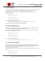
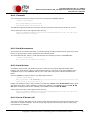
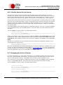
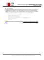
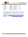
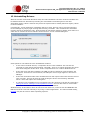
Future Technology Devices International Ltd. Application Note AN_107 Advanced Driver Options Document Reference No.: FT_000073 Version 2.53 Issue Date: 2014-03-13 This application note describes advanced driver settings and operations for FTDI's CDM Windows driver. This is intended to be a reference for experienced engineers developing products incorporating FTDI devices and drivers who are experts with FTDI devices. Future Technology Devices International Limited (FTDI) Unit 1, 2 Seaward Place Centurion Business Park, Glasgow G41 1HH United Kingdom Tel.: +44 (0) 141 429 2777 Fax: + 44 (0) 141 429 2758 E-Mail (Support): [email protected] Web: http://www.ftdichip.com Copyright © 2008-2014 Future Technology Devices International Limited Document Reference No.: FT_000073 Advanced Driver Options AN_107 Application Note AN_107 Version 2.53 Clearance No.: FTDI# 63 Table of Contents 1 Introduction .................................................................... 4 2 CDM USB Serial Converter Properties Page ..................... 5 3 2.1 Loading the COM Port Driver ..................................................... 5 2.2 USB Selective Suspend .............................................................. 5 CDM COM Port Advanced Properties Page ....................... 7 4 Modification of INF for Non-Default VID and PID Values .................................................................................. 9 5 6 4.1 FTDIBUS.INF ............................................................................. 9 4.2 FTDIPORT.INF ........................................................................... 9 FTDIBUS.INF Options .................................................... 11 5.1 Adjusting the Reset Pipe Retry Count ...................................... 11 5.2 Using Location IDs .................................................................. 11 5.3 Limiting the Number of COM Ports That Can Be Installed ........ 13 5.4 Override EEPROM Driver Setting ............................................. 13 5.5 USB Timeout ............................................................................ 15 5.6 Disable EEPROM Writes ........................................................... 15 5.7 USB Selective Suspend ............................................................ 15 FTDIPORT.INF Options .................................................. 17 6.1 Aliasing Baud Rates ................................................................. 17 6.2 Changing the Default USB Transfer Size .................................. 17 6.3 Setting a Custom Default Latency Timer Value ........................ 18 6.4 Enabling Modem Emulation Mode ............................................ 18 6.5 Buffered Writes ....................................................................... 19 6.6 Miscellaneous Options ............................................................. 19 6.6.1 Timeouts ................................................................................................. 20 6.6.2 Serial Enumerator .................................................................................... 20 6.6.3 Serial Printer ........................................................................................... 20 6.6.4 Cancel If Power Off ................................................................................... 20 6.6.5 Event On Surprise Removal ....................................................................... 21 6.6.6 Set RTS On Close ..................................................................................... 21 6.6.7 Disable Modem Ctrl At Startup ................................................................... 22 Copyright © 2008-2014 Future Technology Devices International Limited 2 Document Reference No.: FT_000073 Advanced Driver Options AN_107 Application Note AN_107 Version 2.53 Clearance No.: FTDI# 63 7 6.7 Changing the Driver Priority .................................................... 22 6.8 Specifying the COM Port Allocation Start Value ....................... 23 6.9 USB Selective Suspend ............................................................ 24 System Options ............................................................. 25 7.1 Ignore Hardware Serial Number .............................................. 25 7.2 Phantom Devices ..................................................................... 25 8 Foreign Language Support ............................................ 27 9 Co-Installer ................................................................... 28 10 Renaming Driver Files ................................................... 29 11 Driver Pre-Installation .................................................. 30 11.1 DPInst Packages ..................................................................... 30 12 Uninstalling Drivers ...................................................... 32 13 Contact Information ...................................................... 33 Appendix A – Appendix ........................................................ 1 A.1 FTDIBUS.INF ............................................................................... 1 A.2 FTDIPORT.INF ............................................................................. 4 Appendix B - Revision History .............................................. 9 Copyright © 2008-2014 Future Technology Devices International Limited 3 Document Reference No.: FT_000073 Advanced Driver Options AN_107 Application Note AN_107 Version 2.53 Clearance No.: FTDI# 63 1 Introduction This application note describes advanced driver settings and operations for FTDI's CDM Windows driver. This is intended to be a reference for experienced engineers developing products incorporating FTDI devices and drivers who are experts with FTDI devices. If you are unsure about any of the features described in this document, please do not change any of your driver files or registry settings and seek assistance from FTDI Support. Copyright © 2008-2014 Future Technology Devices International Limited 4 Document Reference No.: FT_000073 Advanced Driver Options AN_107 Application Note AN_107 Version 2.53 Clearance No.: FTDI# 63 2 CDM USB Serial Converter Properties Page With the CDM driver, a property page is now available for the USB Serial Converter driver. This is at the same level as the original D2XX driver. Figure 2.1 USB Serial Converter Properties 2.1 Loading the COM Port Driver In the case of FT232R, FT245R and FT2232 devices, the driver type is determined by a setting in the device EEPROM. The Advanced tab allows the user to override any EEPROM settings to select the driver type. The EEPROM settings can be overridden using the check box shown below: This option can also be configured as a default value via the FTDIBUS.INF file before installation as indicated in FTDIBUS.INF Options. If this is set, the EEPROM driver setting will be ignored. 2.2 USB Selective Suspend The USB Serial Converter driver supports USB Selective Suspend, a feature that allows the system to suspend devices that are not in use and thus reduce overall power consumption. This option is enabled when the “Enable Selective Suspend” checkbox is checked. The period of inactivity used to determine that the device is not in use is selected from values ranging between 1 second and 1 hour that are presented in the “Idle Timeout” pull-down box. The default value for the Idle Timeout is 5 seconds. Copyright © 2008-2014 Future Technology Devices International Limited 5 Document Reference No.: FT_000073 Advanced Driver Options AN_107 Application Note AN_107 Version 2.53 Clearance No.: FTDI# 63 Note that “Load VCP” must be unchecked in order to enable Selective Suspend. Copyright © 2008-2014 Future Technology Devices International Limited 6 Document Reference No.: FT_000073 Advanced Driver Options AN_107 Application Note AN_107 Version 2.53 Clearance No.: FTDI# 63 3 CDM COM Port Advanced Properties Page An advanced properties page is available for devices using VCP drivers. To access the advanced properties page in Windows 2000 or Windows XP, go to "Control Panel > System" then select the "Hardware" tab and click "Device Manager…", or "Control Panel > Device Manager" in Vista. Find the USB serial port you want to change the properties of and right-click on it. Select "Properties" from the menu then select the "Port Settings" tab to get the window below. Figure 3.1 USB Serial (COM3) Properties This page allows configuration of the basic device parameters (i.e. Baud rate, data bits, parity, stop bits and flow control). To access more advanced settings, click on the "Advanced…" button to display the advanced properties page (shown below). Copyright © 2008-2014 Future Technology Devices International Limited 7 Document Reference No.: FT_000073 Advanced Driver Options AN_107 Application Note AN_107 Version 2.53 Clearance No.: FTDI# 63 This page will allow the following parameters to be altered: COM port number USB buffer sizes Latency timer value Read and write timeout values Miscellaneous options USB Selective Suspend These options can also be configured as default values via the FTDIPORT.INF file before installation as indicated in FTDIPORT.INF Options. The miscellaneous options are covered in Miscellaneous Options. Copyright © 2008-2014 Future Technology Devices International Limited 8 Document Reference No.: FT_000073 Advanced Driver Options AN_107 Application Note AN_107 Version 2.53 Clearance No.: FTDI# 63 4 Modification of INF for Non-Default VID and PID Values In order to use FTDI drivers with devices that are identified by a VID and PID combination other than FTDI's VID and the device default PID, the driver INF files must be modified to match the desired VID and PID combination. The following sections indicate which references must be modified for the drivers to function correctly with alternative VIDs and PIDs. There is also some useful information on the modification of INF files for custom VID and PID values in the MProg user manual which is available from the FTDI Knowledgebase. 4.1 FTDIBUS.INF In order that Windows successfully match a device with the driver, the VID and PID programmed into the device must be listed in the driver INF file. The following sections of FTDIBUS.INF show text in bold that must be amended to match the desired VID and PID combination: [FtdiHw] %USB\VID_0403&PID_6001.DeviceDesc%=FtdiBus,USB\VID_0403&PID_6001 [FtdiHw.NTamd64] %USB\VID_0403&PID_6001.DeviceDesc%=FtdiBus.NTamd64,USB\VID_0403&PID_6001 Also, in the case of the FTDIBUS.INF file FT2232 devices must have each interface listed as follows: [FtdiHw] %USB\VID_0403&PID_6010&MI_00.DeviceDesc%=FtdiBus,USB\VID_0403&PID_6010&MI_00 %USB\VID_0403&PID_6010&MI_01.DeviceDesc%=FtdiBus,USB\VID_0403&PID_6010&MI_01 [FtdiHw.NTamd64] %USB\VID_0403&PID_6010&MI_00.DeviceDesc%=FtdiBus.NTamd64,USB\VID_0403&PID_6010&MI_00 %USB\VID_0403&PID_6010&MI_01.DeviceDesc%=FtdiBus.NTamd64,USB\VID_0403&PID_6010&MI_01 The device description string may be modified to display a custom device port name in the device manager if so desired in the section listed below: [Strings] Ftdi=”FTDI” USB\VID_0403&PID_6001.DeviceDesc="USB Serial Converter" and for FT2232 devices: [Strings] Ftdi=”FTDI” USB\VID_0403&PID_6010&MI_00.DeviceDesc="USB Serial Converter A" USB\VID_0403&PID_6010&MI_01.DeviceDesc="USB Serial Converter B" Note: The values shown here are the default values already certified by FTDI. When changing FTDIBUS.INF to match a new VID and PID combination, all references to these default values must be removed from the file. See Technical Note http://www.ftdichip.com/Support/Documents/TechnicalNotes/TN_102_OEM_Technical_Support_Re quirements_for_FTDI_Products.pdf for FTDI Products and Application Note http://www.ftdichip.com/Support/Documents/AppNotes/AN_101_WHQL_Certified_Driver_Process. pdf for more details. A sample FTDIBUS.INF file is included in the appendix. 4.2 FTDIPORT.INF Copyright © 2008-2014 Future Technology Devices International Limited 9 Document Reference No.: FT_000073 Advanced Driver Options AN_107 Application Note AN_107 Version 2.53 Clearance No.: FTDI# 63 In addition to the modifications made to the FTDIBUS.INF file to accommodate driver matching, the following entries in the FTDIPORT.INF file show text in bold that must be changed to match the VID and PID combination: [FtdiHw] %VID_0403&PID_6001.DeviceDesc%=FtdiPort,FTDIBUS\COMPORT&VID_0403&PID_6001 [FtdiHw.NTamd64] %VID_0403&PID_6001.DeviceDesc%=FtdiPort,FTDIBUS\COMPORT&VID_0403&PID_6001 In the case of the FTDIPORT.INF file, separate entries are not needed for each interface of FT2232 and FT4232 devices as each port of these is supported by the same entry: [FtdiHw] %VID_0403&PID_6010.DeviceDesc%=FtdiPort,FTDIBUS\COMPORT&VID_0403&PID_6010 [FtdiHw.NTamd64] %VID_0403&PID_6010.DeviceDesc%=FtdiPort,FTDIBUS\COMPORT&VID_0403&PID_6010 The device description string may be modified to display a custom device port name in the device manager if so desired in the section listed below: [Strings] Ftdi=”FTDI” VID_0403&PID_6001.DeviceDesc="USB Serial Port" Note: The values shown here are the default values already certified by FTDI. When changing FTDIBUS.INF to match a new VID and PID combination, all references to these default values must be removed from the file. See Technical Note OEM Technical Support Requirements for FTDI Products and Application Note Using Microsoft's WHQL Process for Certifying Customer Modified FTDI Driver Files for more details A sample FTDIPORT.INF file is included in the appendix. Copyright © 2008-2014 Future Technology Devices International Limited 10 Document Reference No.: FT_000073 Advanced Driver Options AN_107 Application Note AN_107 Version 2.53 Clearance No.: FTDI# 63 5 FTDIBUS.INF Options Some default configuration options are configurable through FTDIBUS.INF. This section describes the options available and how to implement them. 5.1 Adjusting the Reset Pipe Retry Count In some rare cases, it may be necessary to increase the number of times the driver tries to reset a USB pipe on which an error has occurred, for example in noisy environments where USB errors can occur. The default value for the reset pipe request retry count is 50. This default value may be changed in the FTDIBUS.INF file by editing or including the following fragment. [FtdiBus.NT.AddService] AddReg = FtdiBus.NT.AddService.AddReg [FtdiBus.NT.AddService.AddReg] HKR,Parameters,"RetryResetCount",0x00010001,100 In this example fragment, the reset pipe request is set to 100. This value is held in the registry key located at: HKEY_LOCAL_MACHINE\SYSTEM\CurrentControlSet\Services\FTDIBUS\Parameters\RetryResetCoun t 5.2 Using Location IDs In some application areas it may be desirable to install devices by physical location rather than serial number. In these instances, this may be accomplished by using the LocIds entry in the driver INF file. The driver uses LocIds to define the set of USB ports supported. It can be used in systems that require only certain USB ports to be available, perhaps in conjunction with MaxDevs. The default behaviour is that all USB ports are supported. The default can be overridden by including LocIds in the FTDIBUS.INF service key section. [FtdiBus.NT.AddService] AddReg = FtdiBus.NT.AddService.AddReg [FtdiBus.NT.AddService.AddReg] HKR,Parameters,"LocIds",1,21,00,00,00,32,00,00,00,11,00,00,00,00 In this example INF file fragment, three USB ports are supported. Location ID 0x00000021 represents host controller 1 port 1. Location ID 0x00000032 represents host controller 2 port 2. Location ID 0x00000011 represents host controller 0 port 1. This value is held in the registry key located at HKEY_LOCAL_MACHINE\SYSTEM\CurrentControlSet\Services\FTDIBUS\Parameters\LocIds Note that setting LocIds will radically alter the behaviour of the driver; please contact FTDI if you think you have to change LocIds. Location IDs can be obtained using the latest version of the USBView utility available from the Utilities section of the FTDI website. An application note on location IDs AN232B-07 Configuring FTDI's VCP Drivers to use Location ID's is also available. Copyright © 2008-2014 Future Technology Devices International Limited 11 Document Reference No.: FT_000073 Advanced Driver Options AN_107 Application Note AN_107 Version 2.53 Clearance No.: FTDI# 63 USBView can be configured to show location IDs by selecting Options > Location IDs. The screen shot below shows a PC with a hub connected to location 0x0000002A and devices connected at locations 0x00000019 and 0x00002A3. Figure 5.1 USB View The INF entries for the devices connected to these ports would be [FtdiBus.NT.AddService.AddReg] HKR,Parameters,"LocIds",1,19,00,00,00,03,2A,00,00,00 Please note that the INF entry must end with an additional 00 entry to terminate the location ID list. If an attempt is made to install a device at a location that is not supported, a Code 10 error ("This device cannot start") is generated for the new device. Note that Location IDs are represented in the LocIds field as 4 hexadecimal bytes and in byte reversed order. Note also that although on USB host controllers are indexed from 0 and ports from 1, Location IDs are calculated by adjusting the host controller number so that it is indexed from 1 Copyright © 2008-2014 Future Technology Devices International Limited 12 Document Reference No.: FT_000073 Advanced Driver Options AN_107 Application Note AN_107 Version 2.53 Clearance No.: FTDI# 63 5.3 Limiting the Number of COM Ports That Can Be Installed The number of FTDI virtual COM ports that may be installed in a system can be limited by setting the MaxDevs parameter. MaxDevs defaults to 0, meaning that the feature is disabled and the driver will always attempt to create a COM port. The default can be overridden by including a nonzero MaxDevs value in the FTDIBUS.INF service key section. [FtdiBus.NT.AddService] AddReg = FtdiBus.NT.AddService.AddReg [FtdiBus.NT.AddService.AddReg] HKR,Parameters,"MaxDevs",0x00010001,3 In this example INF file fragment, the maximum number of devices is set to 3. This value is held in the registry key located at HKEY_LOCAL_MACHINE\SYSTEM\CurrentControlSet\Services\FTDIBUS\Parameters\MaxDevs If an attempt is made to install more than MaxDevs devices, a Code 10 error ("This device cannot start") is generated for the new device. Note that setting MaxDevs to a value other than zero will radically alter the behaviour of the driver; please contact FTDI if you think you have to change MaxDevs. 5.4 Override EEPROM Driver Setting In the case if FT232R, FT245R and FT2232 devices, the driver will read the device EEPROM to determine whether to expose a COM port or not. The earlier B and AM series devices do not have an EEPROM setting for driver type, so will default to installing a COM port. This feature can be turned off and the choice of driver to load can be made through a setting in the installation file. For a standard installation, the following sections can be added to FTDIBUS.INF to override the EEPROM configuration and load the VCP driver: [FtdiBus.NT.HW] AddReg=FtdiBus.NT.HW.AddReg [FtdiBus.NTamd64.HW] AddReg=FtdiBus.NT.HW.AddReg [FtdiBus.NT.HW.AddReg] HKR,,"ConfigData",0x00010001,4 Bit 2 of the ConfigData parameter determines the driver to be loaded: if it is set to 1, the VCP driver is loaded (as in the above example); otherwise, only the D2XX driver is loaded. Therefore, adding the above sections to the installation file, and in particular setting the value of ConfigData to 4, will cause the VCP driver to be loaded regardless of the EEPROM settings. This method can be extended for the dual channel FT2232 device. In this case, new sections have to be created for each channel to allow the channels to be configured and installed separately. The following fragments show the additional changes that are necessary to configure channel A to load the D2XX driver only, and channel B to load the VCP driver. [FtdiHw] %USB\VID_0403&PID_6010&MI_00.DeviceDesc%=FtdiBusA,USB\VID_0403&PID_6010&MI_00 %USB\VID_0403&PID_6010&MI_01.DeviceDesc%=FtdiBusB,USB\VID_0403&PID_6010&MI_01 [FtdiHw.NTamd64] %USB\VID_0403&PID_6010&MI_00.DeviceDesc%=FtdiBusA.NTamd64,USB\VID_0403&PID_6010&MI_00 %USB\VID_0403&PID_6010&MI_01.DeviceDesc%=FtdiBusB.NTamd64,USB\VID_0403&PID_6010&MI_01 [FtdiBusA.NT] Copyright © 2008-2014 Future Technology Devices International Limited 13 Document Reference No.: FT_000073 Advanced Driver Options AN_107 Application Note AN_107 Version 2.53 Clearance No.: FTDI# 63 CopyFiles=FtdiBus.NT.Copy,FtdiBus.NT.Copy2 AddReg=FtdiBusA.NT.AddReg [FtdiBusA.NTamd64] CopyFiles=FtdiBus.NTamd64.Copy,FtdiBus.NTamd64.Copy2,FtdiBus.NTamd64.Copy3 AddReg=FtdiBusA.NT.AddReg [FtdiBusA.NT.HW] AddReg=FtdiBusA.NT.HW.AddReg [FtdiBusA.NTamd64.HW] AddReg=FtdiBusA.NT.HW.AddReg [FtdiBusA.NT.HW.AddReg] HKR,,"ConfigData",0x00010001,0 [FtdiBusA.NT.Services] AddService = FTDIBUS, 0x00000002, FtdiBus.NT.AddService [FtdiBusA.NTamd64.Services] AddService = FTDIBUS, 0x00000002, FtdiBus.NT.AddService [FtdiBusB.NT] CopyFiles=FtdiBus.NT.Copy,FtdiBus.NT.Copy2 AddReg=FtdiBusB.NT.AddReg [FtdiBusB.NTamd64] CopyFiles=FtdiBus.NTamd64.Copy,FtdiBus.NTamd64.Copy2,FtdiBus.NTamd64.Copy3 AddReg=FtdiBusB.NT.AddReg [FtdiBusB.NT.HW] AddReg=FtdiBusA.NT.HW.AddReg [FtdiBusB.NTamd64.HW] AddReg=FtdiBusA.NT.HW.AddReg [FtdiBusB.NT.HW.AddReg] HKR,,"ConfigData",0x00010001,4 [FtdiBusB.NT.Services] AddService = FTDIBUS, 0x00000002, FtdiBus.NT.AddService [FtdiBusB.NTamd64.Services] AddService = FTDIBUS, 0x00000002, FtdiBus.NT.AddService Note that the value of ConfigData is set to 0 for channel A (D2XX) and the value of ConfigData is set to 4 for channel B (VCP) to achieve the required configuration. Of course, if ConfigData is not included in the installation file, the EEPROM settings will determine which driver is loaded. The ConfigData parameter is held in the registry under the key HKEY_LOCAL_MACHINE\SYSTEM\CurrentControlSet\Enum\USB\{Device VID, PID and interface}\{Serial number}\DeviceParameters\ConfigData The COM port can also be suppressed after installation through the Advanced tab of the USB Serial Converter properties page which is available through the device manager. Copyright © 2008-2014 Future Technology Devices International Limited 14 Document Reference No.: FT_000073 Advanced Driver Options AN_107 Application Note AN_107 Version 2.53 Clearance No.: FTDI# 63 5.5 USB Timeout The USB timeout is the maximum time in milliseconds that a USB request can remain outstanding. It is unlikely that this will ever need to be changed from the 5000ms default value. This USB timeout (in milliseconds) is configurable through the FTDIBUS INF file in the INF fragments shown below: [FtdiBus.NT.HW] AddReg=FtdiBus.NT.HW.AddReg [FtdiBus.NTamd64.HW] AddReg=FtdiBus.NT.HW.AddReg [FtdiBus.NT.HW.AddReg] HKR,,"USBTimeout",0x00010001,5000 which corresponds to the registry entry HKEY_LOCAL_MACHINE\SYSTEM\CurrentControlSet\Enum\USB\{Device VID, PID and interface}\{Serial number}\DeviceParameters\USBTimeout The default value for the USB Timeout is 5 seconds (5000ms). 5.6 Disable EEPROM Writes In some cases, it may be desirable to disable the ability to write to the device EEPROM. This can be accomplished through a ConfigData bit in the FTDIBUS INF file. The driver can be made to ignore any EEPROM write requests by setting bit 0 of the ConfigData field as shown in the INF fragment below: [FtdiBus.NT.HW] AddReg=FtdiBus.NT.HW.AddReg [FtdiBus.NTamd64.HW] AddReg=FtdiBus.NT.HW.AddReg [FtdiBus.NT.HW.AddReg] HKR,,"ConfigData",0x00010001,1 which corresponds to the registry key HKEY_LOCAL_MACHINE\SYSTEM\CurrentControlSet\Enum\USB\{Device VID, PID and interface}\{Serial number}\DeviceParameters\ConfigData 5.7 USB Selective Suspend The CDM driver supports USB Selective Suspend, a feature that allows the system to suspend devices that are not in use and thus reduce overall power consumption. USB Selective Suspend is controlled through bit 5 of the ConfigData parameter and the SSIdleTimeout value (in milliseconds) in the FTDIBUS.INF file. For a standard installation, the following sections can be added to FTDIBUS.INF to enable Selective Suspend: [FtdiBus.NT.HW] AddReg=FtdiBus.NT.HW.AddReg [FtdiBus.NTamd64.HW] AddReg=FtdiBus.NT.HW.AddReg [FtdiBus.NT.HW.AddReg] Copyright © 2008-2014 Future Technology Devices International Limited 15 Document Reference No.: FT_000073 Advanced Driver Options AN_107 Application Note AN_107 Version 2.53 Clearance No.: FTDI# 63 HKR,,"ConfigData",0x00010001,0x20 HKR,,"SSIdleTimeout",0x00010001,10000 This INF file fragment shows Selective Suspend enabled, and the Idle Timeout value set to 10 seconds. These values are held in the registry under this key: HKEY_LOCAL_MACHINE\SYSTEM\CurrentControlSet\Enum\FTDIBUS\{Device VID, PID and serial number}\0000\Device Parameters NOTE: If setting selective suspend for the driver bus layer it must not be set in the port layer (see section 6.9) Copyright © 2008-2014 Future Technology Devices International Limited 16 Document Reference No.: FT_000073 Advanced Driver Options AN_107 Application Note AN_107 Version 2.53 Clearance No.: FTDI# 63 6 FTDIPORT.INF Options There are many configuration options available through FTDIPORT.INF. This section describes these options and how to configure them. 6.1 Aliasing Baud Rates FTDI devices can support non-standard Baud rates. It is not necessary to alias Baud rates to achieve this, but in cases where the application software tries to set a standard Baud rate and a non-standard Baud rate is desired, this can be achieved by aliasing non-standard baud rates. Baud rates are calculated using a Baud rate divisor. The file FTDIPORT.INF contains entries that are used as the divisors for standard baud rates. By changing these values it is possible to alias standard baud rates with non-standard values - for instance replacing 115k Baud with 512k Baud. Users would then set up the device to operate at 512k Baud by selecting 115k Baud for the USB serial port. The procedure for calculating Baud rate divisors is described fully in application note AN232B-05 Configuring FT232R, FT2232 and FT232B Baud Rates. The FT8U232AM device supports sub-integer divisors of 0, 0.5, 0.25 and 0.125 only. These values can be configured through a Baud rate divisor table with two elements to define a Baud rate. The extract below from FTDIPORT.INF gives an example of the Baud rate table for standard Baud rates for the FT8U232AM device. Note that the Baud rate table is one line in the INF. [FtdiPort.NT.HW.AddReg] HKR,,"ConfigData",1,01,00,3F,3F,10,27,88,13,C4,09,E2,04,71,02,38,41,9C,80,4E,C0,34,00, 1A,00,0D,00,06,40,03,80,00,00,D0,80 In the case of the FT232R, FT2232 and FT232B devices, sub-integer divisors of 0, 0.5, 0.25, 0.125, 0.375, 0.625, 0.75 and 0.875 are supported. This requires that the Baud rate table be extended to four elements per Baud rate as indicated below. This example extract shows the fourelement Baud rate table for standard Baud rates. As with the original divisors, note that the Baud rate table is one line in the INF. [FtdiPort.NT.HW.AddReg] HKR,,"ConfigData",1,11,00,3F,3F,10,27,00,00,88,13,00,00,C4,09,00,00,E2,04,00,00,71,02, 00,00,38,41,00,00,9C,80,00,00,4E,C0,00,00,34,00,00,00,1A,00,00,00,0D,00,00,00,06,40,00 ,00,03,80,00,00,00,00,00,00,D0,80,00,00 The Baud rate table used by each device is located in the registry under HKEY_LOCAL_MACHINE\SYSTEM\CurrentControlSet\Enum\FTDIBUS\{Device VID, PID and serial number}\0000\Device Parameters\ConfigData Please note that the four-element table will not allow the use of the additional sub-integer divisors with FT8U232AM devices. The two-element table will work with all devices. For a full explanation of calculating non-standard Baud rate divisors and how to arrange them in the Baud rate table, see application note AN232B-05 Configuring FT232R, FT2232 and FT232B Baud Rates. 6.2 Changing the Default USB Transfer Size The default USB transfer size may be set up at installation through the ConfigData entry in the FTDIPORT.INF file. This is the same entry that contains the Baud rate table. The options can be set through the first DWORD of the table (shown in bold below) [FtdiPort.NT.HW.AddReg] Copyright © 2008-2014 Future Technology Devices International Limited 17 Document Reference No.: FT_000073 Advanced Driver Options AN_107 Application Note AN_107 Version 2.53 Clearance No.: FTDI# 63 HKR,,"ConfigData",1,01,00,3F,3F,10,27,88,13,C4,09,E2,04,71,02,38,41,9C,80,4E,C0,34,00, 1A,00, 0D,00,06,40,03,80,00,00,D0,80 This entry is byte-reversed, so MSB the DWORD reads 3F 3F 00 01 and the least significant bit is Bit 0. The values are given as follows: Bits 16 - 23: Receive transfer size Bits 24 - 31: Transmit transfer size The maximum value permitted in each case is 3F this is the standard default value. The transfer size in bytes may be calculated as Transfer size in bytes = (Transfer size entry + 1) * 0x40 The USB transfer sizes used by a device are located in the registry under HKEY_LOCAL_MACHINE\SYSTEM\CurrentControlSet\Enum\FTDIBUS\{Device VID, PID and serial number}\0000\Device Parameters\ConfigData 6.3 Setting a Custom Default Latency Timer Value The latency timer is a form of time-out mechanism for the read buffer of FTDI devices. When a FT_Read instruction is sent to the device, data will not be sent back to the host PC until the requested number of bytes has been read. If the requested number of bytes never comes, the device would not send data back. The latency timer counts from the last time data was sent back to the PC. If the latency timer expires, the device will send what data it has available to the PC regardless of how many bytes it is waiting on. The latency timer will then reset and begin counting again. The default value for the latency timer is 16ms. This value may be customised by adding or changing the following entries in the FTDIPORT.INF file of the driver before installation. [FtdiPort.NT.HW.AddReg] HKR,,"LatencyTimer",0x00010001,50 This example will set the default latency timer value to 50ms. The valid range for the latency timer is 1ms - 255ms, although 1ms is not recommended as this is the same as the USB frame length. The latency timer value is held in the registry under HKEY_LOCAL_MACHINE\SYSTEM\CurrentControlSet\Enum\FTDIBUS\{Device VID, PID and serial number}\0000\Device Parameters\LatencyTimer Please see AN232B-04 Data Throughput, Latency and Handshaking for additional information on the latency timer. 6.4 Enabling Modem Emulation Mode Modem emulation mode allows binary data to be transmitted over a two (or more) wire interface with full handshaking and modem control signalling, thus allowing PPP connections to be made. Possible applications include mobile phone data cables, and radio links. Including the following entries in the FTDIPORT.INF file for the VCP driver before installation enables modem emulation mode: [FtdiPort.NT.HW.AddReg] HKR,,"EmulationMode",0x00010001,0x0000nnnn This creates a registry entry under HKEY_LOCAL_MACHINE\SYSTEM\CurrentControlSet\Enum\FTDIBUS\{Device VID, PID and serial number}\0000\Device Parameters\EmulationMode Copyright © 2008-2014 Future Technology Devices International Limited 18 Document Reference No.: FT_000073 Advanced Driver Options AN_107 Application Note AN_107 Version 2.53 Clearance No.: FTDI# 63 Please see AN232B-09 Using the Modem Emulation Mode in FTDI's VCP Driver for additional information on modem emulation mode. 6.5 Buffered Writes In some cases, it is possible that the hardware developer does not have control over the application software. This can cause problems when migrating from RS232 to USB, as applications written for RS232 typically write bytes to the port one at a time and this will have a detremental effect on the USB performance. Due to the packetised nature of USB, it is far more efficient to transfer data in large chunks. This can be achieved by bufferring the data within the application. If the developer does not have control over the application software to allow for buffering the data there, the FTDI driver provides an option to buffer the data from the application in the driver before sending the data out over USB to the device. The Buffered Writes option is enabled through bit 10 of the first DWORD of the ConfigData entry in the FTDIPORT.INF file. This is the same entry that contains the Baud rate table. The first DWORD is shown in bold in the INF fragment below. [FtdiPort.NT.HW.AddReg] HKR,,"ConfigData",1,01,00,3F,3F,10,27,88,13,C4,09,E2,04,71,02,38,41,9C,80,4E,C0,34,00, 1A,00, 0D,00,06,40,03,80,00,00,D0,80 Please note that the ConfigData entry is byte-reversed, so MSB the DWORD reads 3F 3F 00 01 and the least significant bit is Bit 0. With Buffered Writes disabled, the DWORD would read 3F 3F 00 01. With Buffered Writes enabled, the DWORD would read 3F 3F 04 01. In addition to enabling buffered writes in the Config Data entry, some parameters must be set up to control the behaviour. These parameters can also be set up in FTDIPORT.INF as follows: [FtdiPort.NT.HW.AddReg] HKR,,"WriteBufferSize",0x00010001,4096 HKR,,"WriteBufferThreshold",0x00010001,20 HKR,,"WriteLatency",0x00010001,6 These values are held in the registry under this key: HKEY_LOCAL_MACHINE\SYSTEM\CurrentControlSet\Enum\FTDIBUS\{Device VID, PID and serial number}\0000\Device Parameters These parameters are specific to the application. As such, they will require to be "tuned" to provide best performance. 6.6 Miscellaneous Options Miscellaneous options available on the COM port advanced properties page may be set up at installation through the INF sections covered in this section. Timeouts Serial Enumerator Serial Printer Cancel If Power Off Event On Surprise Removal Set RTS On Close Disable Modem Ctrl At Startup Copyright © 2008-2014 Future Technology Devices International Limited 19 Document Reference No.: FT_000073 Advanced Driver Options AN_107 Application Note AN_107 Version 2.53 Clearance No.: FTDI# 63 6.6.1 Timeouts The read and write timeout values may be set through the FTDIPORT.INF file. [FtdiPort.NT.HW.AddReg] HKR,,"MinReadTimeout",0x00010001,0 HKR,,"MinWriteTimeout",0x00010001,0 This INF file fragment shows the minimum read and minimum write timeout values set to 0ms. These values are held in the registry under this key: HKEY_LOCAL_MACHINE\SYSTEM\CurrentControlSet\Enum\FTDIBUS\{Device VID, PID and serial number}\0000\Device Parameters 6.6.2 Serial Enumerator The function of the serial enumerator is to detect a Plug-and-Play enabled device (such as a serial mouse or serial modem) that is attached to the USB serial port. The Serial Enumerator option is controlled through the following entries in FTDIPORT.INF: [FtdiPort.NT.HW.AddReg] HKR,,"UpperFilters",0x00010000,"serenum" 6.6.3 Serial Printer If enabled, serial printer will disable timeouts to allow for long delays associated with paper loading. The Serial Printer option is controlled through bit 7 of byte 0 of the first DWORD of the ConfigData entry in the FTDIPORT.INF file. This is the same entry that contains the Baud rate table. The first DWORD is shown in bold in the INF fragment below. [FtdiPort.NT.HW.AddReg] HKR,,"ConfigData",1,01,00,3F,3F,10,27,88,13,C4,09,E2,04,71,02,38,41,9C,80,4E,C0,34,00, 1A,00, 0D,00,06,40,03,80,00,00,D0,80 Please note that this entry is byte-reversed, so MSB the DWORD reads 3F 3F 00 01 and the least significant bit is Bit 0. When disabled (serial printer disabled), the DWORD would read 3F 3F 00 01. When enabled (serial printer enabled), the DWORD would read 3F 3F 00 81. These values are held in the registry under this key: HKEY_LOCAL_MACHINE\SYSTEM\CurrentControlSet\Enum\FTDIBUS\{Device VID, PID and serial number}\0000\Device Parameters\ConfigData 6.6.4 Cancel If Power Off The Cancel If Power Off option can be used to assist with problems encountered when going into a hibernate or suspend condition. This will cancel any requests received by the driver when going into hibernate or suspend. Copyright © 2008-2014 Future Technology Devices International Limited 20 Document Reference No.: FT_000073 Advanced Driver Options AN_107 Application Note AN_107 Version 2.53 Clearance No.: FTDI# 63 The Cancel If Power Off option is controlled through bit 6 of byte 0 of the first DWORD of the ConfigData entry in the FTDIPORT.INF file. This is the same entry that contains the Baud rate table. The first DWORD is shown in bold in the INF fragment below. [FtdiPort.NT.HW.AddReg] HKR,,"ConfigData",1,01,00,3F,3F,10,27,88,13,C4,09,E2,04,71,02,38,41,9C,80,4E,C0,34,00, 1A,00, 0D,00,06,40,03,80,00,00,D0,80 Please note that this entry is byte-reversed, so MSB the DWORD reads 3F 3F 00 01 and the least significant bit is Bit 0. When disabled (no cancel on power off), the DWORD would read 3F 3F 00 01. When enabled (cancel on power off), the DWORD would read 3F 3F 00 41. These values are held in the registry under this key: HKEY_LOCAL_MACHINE\SYSTEM\CurrentControlSet\Enum\FTDIBUS\{Device VID, PID and serial number}\0000\Device Parameters\ConfigData 6.6.5 Event On Surprise Removal The Event On Surprise Removal option is generally left unselected. If an application sets SERIAL_EV_EVENT2 (see NTDDSER.H) in it's event bitmask and this feature is enabled, the driver will signal this event on surprise removal. The Event On Surprise Removal option is controlled through bit 5 of byte 0 of the first DWORD of the ConfigData entry in the FTDIPORT.INF file. This is the same entry that contains the Baud rate table. The first DWORD is shown in bold in the INF fragment below. [FtdiPort.NT.HW.AddReg] HKR,,"ConfigData",1,01,00,3F,3F,10,27,88,13,C4,09,E2,04,71,02,38,41,9C,80,4E,C0,34,00, 1A,00, 0D,00,06,40,03,80,00,00,D0,80 Please note that this entry is byte-reversed, so MSB the DWORD reads 3F 3F 00 01 and the least significant bit is Bit 0. When disabled (no event on surprise removal), the DWORD would read 3F 3F 00 01. When enabled (event on surprise removal), the DWORD would read 3F 3F 00 21. These values are held in the registry under this key: HKEY_LOCAL_MACHINE\SYSTEM\CurrentControlSet\Enum\FTDIBUS\{Device VID, PID and serial number}\0000\Device Parameters\ConfigData 6.6.6 Set RTS On Close Selecting the Set RTS On Close option will set the RTS signal on closing the port. The Set RTS On Close option is controlled through bit 3 of byte 0 of the first DWORD of the ConfigData entry in the FTDIPORT.INF file. This is the same entry that contains the Baud rate table. The first DWORD is shown in bold in the INF fragment below. [FtdiPort.NT.HW.AddReg] HKR,,"ConfigData",1,01,00,3F,3F,10,27,88,13,C4,09,E2,04,71,02,38,41,9C,80,4E,C0,34,00, 1A,00, 0D,00,06,40,03,80,00,00,D0,80 Please note that this entry is byte-reversed, so MSB the DWORD reads 3F 3F 00 01 and the least significant bit is Bit 0. When disabled (RTS not set on close), the DWORD would read 3F 3F 00 01. When enabled (RTS set on close), the DWORD would read 3F 3F 00 09. These values are held in the registry under this key: HKEY_LOCAL_MACHINE\SYSTEM\CurrentControlSet\Enum\FTDIBUS\{Device VID, PID and serial number}\0000\Device Parameters\ConfigData Copyright © 2008-2014 Future Technology Devices International Limited 21 Document Reference No.: FT_000073 Advanced Driver Options AN_107 Application Note AN_107 Version 2.53 Clearance No.: FTDI# 63 6.6.7 Disable Modem Ctrl At Startup This option is used to control the modem control signals DTR and RTS at startup. In normal operation, the modem control signals at startup follow the behaviour of the legacy port. However, due to timing differences between a legacy COM port and a virtual COM port, a "spike" on one of these signals in the legacy port can appear as an assertion of the signal in the virtual COM port. Devices that monitor these signals can enter the wrong state after an unplug-replug cycle on USB. Note that if the "Serial Enumerator" option in the property page is selected, then the enumeration sequence causes the modem control signals to change at startup. So if it is necessary to select "Disable Modem Ctrl At Startup", then it is likely that "Serial Enumerator" should be unchecked in the property page. The Disable Modem Ctrl At Startup option is controlled through bit 1 of byte 1 of the first DWORD of the ConfigData entry in the FTDIPORT.INF file. This is the same entry that contains the Baud rate table. The first DWORD is shown in bold in the INF fragment below. [FtdiPort.NT.HW.AddReg] HKR,,"ConfigData",1,01,00,3F,3F,10,27,88,13,C4,09,E2,04,71,02,38,41,9C,80,4E,C0,34,00, 1A,00, 0D,00,06,40,03,80,00,00,D0,80 Please note that this entry is byte-reversed, so MSB the DWORD reads 3F 3F 00 01 and the least significant bit is Bit 0. When disabled(modem control at startup enabled), the DWORD would read 3F 3F 00 01. When enabled (modem control at startup disabled), the DWORD would read 3F 3F 02 01. Alternatively, the default can be overridden by directly editing the ConfigData parameter in the virtual COM port's registry entry. HKEY_LOCAL_MACHINE\SYSTEM\CurrentControlSet\Enum\FTDIBUS\VID_0403+PID_6001+12345678\00 00\DeviceParameters\ConfigData Note that if DisableModemControlSignalsAtStartup is set TRUE by editing the installation file or the registry, the same considerations as above apply to "Serial Enumerator ". So it may be necessary to remove references to "serenum" in "UpperFilters" in the AddReg sections of the installation file, and in the UpperFilters key in the virtual COM port's registry entry. 6.7 Changing the Driver Priority For some applications (e.g. audio data transmission), it is possible to change the priority level of the driver to provide better performance. The InPriorityLevel and OutPriorityLevel values can be set to a value between 1 and 31. The default value for both of these parameters is 16. The custom driver priority option is enabled through bit 11 of the first DWORD of the ConfigData entry in the FTDIPORT.INF file. This is the same entry that contains the Baud rate table. The first DWORD is shown in bold in the INF fragment below. [FtdiPort.NT.HW.AddReg] HKR,,"ConfigData",1,01,00,3F,3F,10,27,88,13,C4,09,E2,04,71,02,38,41,9C,80,4E,C0,34,00, 1A,00,0D,00,06,40,03,80,00,00,D0,80 [FtdiPort.NTamd64.HW.AddReg] HKR,,"ConfigData",1,01,00,3F,3F,10,27,88,13,C4,09,E2,04,71,02,38,41,9C,80,4E,C0,34,00, 1A,00,0D,00,06,40,03,80,00,00,D0,80 Copyright © 2008-2014 Future Technology Devices International Limited 22 Document Reference No.: FT_000073 Advanced Driver Options AN_107 Application Note AN_107 Version 2.53 Clearance No.: FTDI# 63 Please note that the ConfigData entry is byte-reversed, so MSB the DWORD reads 3F 3F 00 01 and the least significant bit is Bit 0. With the driver default priority, the DWORD would read 3F 3F 00 01. With custom driver priority enabled, the DWORD would read 3F 3F 08 01. In addition to enabling custom driver priority in the Config Data entry, some parameters must be set up to control the behaviour. These parameters can also be set up in FTDIPORT.INF as follows: [FtdiPort.NT.HW.AddReg] HKR,,"InPriorityLevel",0x00010001,16 HKR,,"OutPriorityLevel",0x00010001,16 [FtdiPort.NTamd64.HW.AddReg] HKR,,"InPriorityLevel",0x00010001,16 HKR,,"OutPriorityLevel",0x00010001,16 These values are held in the registry under this key: HKEY_LOCAL_MACHINE\SYSTEM\CurrentControlSet\Enum\FTDIBUS\{Device VID, PID and serial number}\0000\Device Parameters Note that custom driver priority is rarely required and setting driver priority to an excessive level may result in machine lock-up. Use custom driver priority with care and consult FTDI support if in doubt. 6.8 Specifying the COM Port Allocation Start Value As of CDM 2.08.02, the co-installer applies to all FTDI devices and can accept an optional parameter to specify the initial index for COM port allocation. The default behaviour for the CDM driver is to start the allocation at COM3. If a COM port is in use, the next available COM port number will be used. The initial index is specified for a specific VID and PID combination and can be included in the FTDIPORT INF file with the following entry: [FtdiPort.NT.AddService.AddReg] HKR,"Parameters\VID_0403&PID_6001","InitialIndex",0x00010001,14 and the following line should be added to the [FtdiPort.NT.AddService] section: AddReg=FtdiPort.NT.AddService.AddReg This example will cause devices with a VID of 0x0403 and PID of 0x6001 to have their COM ports allocated from COM14 onwards. Note that the VID and PID identifiers in bold in the above example should be customised for the particular device required. This values are held in the registry under this key: HKEY_LOCAL_MACHINE\SYSTEM\CurrentControlSet\services\FTSER2K\VID_{vendorID}&PID_{productI D} Copyright © 2008-2014 Future Technology Devices International Limited 23 Document Reference No.: FT_000073 Advanced Driver Options AN_107 Application Note AN_107 Version 2.53 Clearance No.: FTDI# 63 6.9 USB Selective Suspend The CDM driver supports USB Selective Suspend, a feature that allows the system to suspend devices that are not in use and thus reduce overall power consumption. USB Selective Suspend is controlled through bit 4 of byte 1 of the first DWORD of the ConfigData entry in the FTDIPORT.INF file. This is the same entry that contains the Baud rate table. The first DWORD is shown in bold in the INF fragment below. [FtdiPort.NT.HW.AddReg] HKR,,"ConfigData",1,01,00,3F,3F,10,27,88,13,C4,09,E2,04,71,02,38,41,9C,80,4E,C0,34,00, 1A,00, 0D,00,06,40,03,80,00,00,D0,80 Please note that this entry is byte-reversed, so MSB the DWORD reads 3F 3F 00 01 and the least significant bit is Bit 0. When disabled (Selective Suspend not enabled), the DWORD would read 3F 3F 00 01. When Selective Suspend is enabled, the DWORD would read 3F 3F 10 01. These values are held in the registry under this key: HKEY_LOCAL_MACHINE\SYSTEM\CurrentControlSet\Enum\FTDIBUS\{Device VID, PID and serial number}\0000\Device Parameters\ConfigData The Idle Timeout value may be set through the FTDIPORT.INF file. [FtdiPort.NT.HW.AddReg] HKR,,"SSIdleTimeout",0x00010001,10000 This INF file fragment shows the Idle Timeout value set to 10 seconds (10000 msecs). This value is held in the registry under this key: HKEY_LOCAL_MACHINE\SYSTEM\CurrentControlSet\Enum\FTDIBUS\{Device VID, PID and serial number}\0000\Device Parameters NOTE: If setting selective suspend for the port layer it must not be set in the bus layer (see section 5.7) Copyright © 2008-2014 Future Technology Devices International Limited 24 Document Reference No.: FT_000073 Advanced Driver Options AN_107 Application Note AN_107 Version 2.53 Clearance No.: FTDI# 63 7 System Options 7.1 Ignore Hardware Serial Number If devices have the same vendor ID and product ID but different serial numbers, the system will normally treat them as different devices. This causes the drivers to be installed for each device and create registry entries for each device. It is possible to override this behaviour to make the system ignore a device's serial number and treat all devices with matching VID and PID connected to the same USB port as if they were the same device. This is achieved by adding a REG_BINARY value called IgnoreHWSerNum to the registry and setting it to 01. This value is held in the registry key located at: HKEY_LOCAL_MACHINE\SYSTEM\CurrentControlSet\Control\UsbFlags\IgnoreHWSerNum{Device VID, PID and interface} For a default FTDI device ID (VID 0x0403, PID 0x6001), add the following registry REG_BINARY value set to 01: HKEY_LOCAL_MACHINE\SYSTEM\CurrentControlSet\Control\UsbFlags\IgnoreHWSerNum04036001 For port A of an FT2232 device with default VID and PID, the IgnoreHWSerNum string would be: HKEY_LOCAL_MACHINE\SYSTEM\CurrentControlSet\Control\UsbFlags\IgnoreHWSerNum0403601000 and for port B of an FT2232 device the IgnoreHWSerNum string would be: HKEY_LOCAL_MACHINE\SYSTEM\CurrentControlSet\Control\UsbFlags\IgnoreHWSerNum0403601001 As the FT2232 device also uses the Windows composite device driver, an additional IgnoreHWSerNum entry is required to prevent Windows from creating additional composite driver registry entries: HKEY_LOCAL_MACHINE\SYSTEM\CurrentControlSet\Control\UsbFlags\IgnoreHWSerNum04036010 Now the system can treat devices with the same vendor ID and product ID but different serial numbers as the same device and drivers are installed for the first device only. As such, only one entry is created in the registry. If the device is connected to another USB port, the driver will have to be reinstalled for that port. Note that IgnoreHWSerNum cannot be setup in FTDIBUS.INF or FTDIPORT.INF, it must be setup by editing the registry manually or by an installation utility BEFORE installing the driver. 7.2 Phantom Devices Devices that have been installed on a system but are not currently available are referred to as "phantom devices". These devices are not usually displayed in the device manager, but can be made to be displayed as though they are attached. This allows device properties to be changed or devices to be uninstalled via Device Manger even though the device is not physically connected to the PC. To display phantom devices in Device Manager, a new system variable is required. Open "Control Panel > System" then select the "Advanced" tab and click "Environment Variables". In the System Variables section (NOT THE USER VARIABLES SECTION), click "New..." to display the following window: Copyright © 2008-2014 Future Technology Devices International Limited 25 Document Reference No.: FT_000073 Advanced Driver Options AN_107 Application Note AN_107 Version 2.53 Clearance No.: FTDI# 63 Figure 7.1 Edit System Variable Create a new System Variable called "DevMgr_Show_NonPresent_Devices" and set the value to 1, then click OK. Open the Device Manager ("Control Panel > System" then select the "Hardware" tab and click "Device Manager…", or "Control Panel > Device Manger" in Vista) and select "View > Show Hidden Devices". Device Manager will then show all hidden and phantom devices available on that PC as shaded. Figure 7.2 Device Manager Copyright © 2008-2014 Future Technology Devices International Limited 26 Document Reference No.: FT_000073 Advanced Driver Options AN_107 Application Note AN_107 Version 2.53 Clearance No.: FTDI# 63 8 Foreign Language Support There is a DLL available to display the VCP COM port properties page in languages other than English. To request a new language be made available in the DLL, please contact FTDI Support who will provide the text from the properties page to be translated into the desired language. Once the translated text is returned to FTDI the new language can be implemented in the DLL. Copyright © 2008-2014 Future Technology Devices International Limited 27 Document Reference No.: FT_000073 Advanced Driver Options AN_107 Application Note AN_107 Version 2.53 Clearance No.: FTDI# 63 9 Co-Installer The FT2232 and FT4232 devices are composite USB devices which are capable of providing two or more COM ports to a system. To ensure that the ports of these devices are allocated COM port numbers in the correct order (i.e. port A is allocated before port B) under Windows, a co-installer is used. The coinstaller is specified in the following sections of the FTDIPORT.INF file: [FtdiPort.NT.CoInstallers] AddReg=FtdiPort.NT.CoInstallers.AddReg CopyFiles=FtdiPort.NT.CopyCoInst [FtdiPort.NT.CoInstallers.AddReg] HKR,,CoInstallers32,0x00010000,"ftcserco.Dll,FTCSERCoInstaller" [FtdiPort.NT.CopyCoInst] ftcserco.dll In addition, as of version CDM 2.08.02 the co-installer can specify the initial COM port allocation index for all FTDI devices. This is detailed in section 6.8 Specifying the COM Port Allocation Start Value. Copyright © 2008-2014 Future Technology Devices International Limited 28 Document Reference No.: FT_000073 Advanced Driver Options AN_107 Application Note AN_107 Version 2.53 Clearance No.: FTDI# 63 10 Renaming Driver Files It is possible to rename the driver files to create a unique driver package, but this is not recommended. In order for the renamed driver package to work correctly, all references to file names in the INF files must be updated to use the new file names. FTDI does not currently support users who attempt to rename driver packages. Any changes to an existing WHQL certified driver package, including modified file names, will invalidate the certification. Copyright © 2008-2014 Future Technology Devices International Limited 29 Document Reference No.: FT_000073 Advanced Driver Options AN_107 Application Note AN_107 Version 2.53 Clearance No.: FTDI# 63 11 Driver Pre-Installation Traditionally, the Found New Hardware Wizard has been the regular method for installing new hardware on a Windows machine. Microsoft has recognised that this requires some input from the end-user who may know very little about driver installation. Additionally, many manufacturers would prefer to install the device drivers before the end-user connects the hardware to the PC. Microsoft has addressed this problem by producing a set of driver installation tools called Driver Install Frameworks (DIFx). The simplest tool provided for driver installation is called the Driver Package Installer (DPInst). FTDI's driver packages from VCP 1.00.2176 onwards are compatible with DPInst. 11.1 DPInst Packages In order to be compatible with DPInst, a driver package must be Microsoft WHQL certified and meet certain requirements as outlined in Microsoft Documentation. The standard FTDI CDM driver package meets these requirements if certified, such as CDM 2.02.04. When bundled with DPInst, the driver package typically contains the files shown below: where the i386 subdirectory contains the 32-bit driver files: and the amd64 subdirectory contains the 64-bit driver files: Copyright © 2008-2014 Future Technology Devices International Limited 30 Document Reference No.: FT_000073 Advanced Driver Options AN_107 Application Note AN_107 Version 2.53 Clearance No.: FTDI# 63 In order to use DPInst to install the driver, DPInst.exe must be run. There are two versions of DPInst, a 32-bit version to install the 32-bit driver package (DPInstx86.exe in above screen shot) and a 64-bit version to install the 64-bit driver package (DPInstx64.exe in above screen shot). An automated installer must detect which version of DPInst is required to successfully install the driver package using DPInst. If a custom VID and PID combination is required, FTDI can grant reseller rights to customers with a WinQual account. Details on obtaining reseller right / driver update WHQL certification can be found in application note Using Microsoft's WHQL Process for Certifying Customer Modified FTDI Driver Files. Microsoft charges a small fee for this service. To learn more about using DPInst with FTDI drivers, please see application note AN232R-03 FTDI Windows Driver Pre-installation. Copyright © 2008-2014 Future Technology Devices International Limited 31 Document Reference No.: FT_000073 Advanced Driver Options AN_107 Application Note AN_107 Version 2.53 Clearance No.: FTDI# 63 12 Uninstalling Drivers With the release of Microsoft Windows Vista, the FTDI uninstaller has been rendered unusable due to Windows Resource Protection preventing the executable from deleting driver files and associated registry values. Vista will only allow the system itself to modify files and registry values in these locations. Consequently, a new method for uninstalling has to be used. Devices can be removed using the Device Manager by simply right-clicking and selecting "Uninstall". This will delete the associated registry entries for that device only. Vista provides an automatic method to delete driver files via a check box to "Delete the driver software for this device" on the uninstall dialog box. Figure 12.1 Confirm Device Uninstall Some points to note about the new uninstallation method: In the case of FT2232 devices, a composite device is also installed. This can also be removed by right-clicking and selecting "Uninstall". There is no option the delete the driver files when doing this as the driver for the composite device is a native Windows driver. If the VCP driver has been installed, the COM port driver should be removed before the bus driver. If the bus is removed first, the COM port will no longer appear in the Device Manager. If the files are deleted while other installed devices still require them those devices will not work correctly. This can be fixed by right clicking the device and selecting "Reinstall Driver" which will replace the missing files. If a device to be uninstalled is not connected to the PC, the device can still be removed by setting the device manager to show phantom devices. This can also allow a virtual COM port to be uninstalled if the bus layer has been removed first. Windows 2000, XP and Server 2003 do not have this check box, so driver files and OEM INF and PNF files must be removed manually or by using a custom application. The FTDI Uninstall Utility, FTClean may still be used on these operating systems. Copyright © 2008-2014 Future Technology Devices International Limited 32 Document Reference No.: FT_000073 Advanced Driver Options AN_107 Application Note AN_107 Version 2.53 Clearance No.: FTDI# 63 13 Contact Information Head Office – Glasgow, UK Branch Office – Tigard, Oregon, USA Future Technology Devices International Limited Unit 1, 2 Seaward Place, Centurion Business Park Glasgow G41 1HH United Kingdom Tel: +44 (0) 141 429 2777 Fax: +44 (0) 141 429 2758 Future Technology Devices International Limited (USA) 7130 SW Fir Loop Tigard, OR 97223-8160 USA Tel: +1 (503) 547 0988 Fax: +1 (503) 547 0987 E-mail (Sales) [email protected] E-mail (Support) [email protected] E-mail (General Enquiries) [email protected] E-Mail (Sales) [email protected] E-Mail (Support) [email protected] E-Mail (General Enquiries) [email protected] Branch Office – Shanghai, China Branch Office – Taipei, Taiwan Future Technology Devices International Limited (Taiwan) 2F, No. 516, Sec. 1, NeiHu Road Taipei 114 Taiwan , R.O.C. Tel: +886 (0) 2 8791 3570 Fax: +886 (0) 2 8791 3576 E-mail (Sales) E-mail (Support) E-mail (General Enquiries) [email protected] [email protected] [email protected] Future Technology Devices International Limited (China) Room 1103, No. 666 West Huaihai Road, Shanghai, 200052 China Tel: +86 21 62351596 Fax: +86 21 62351595 E-mail (Sales) [email protected] E-mail (Support) [email protected] E-mail (General Enquiries) [email protected] web Site http://ftdichip.com System and equipment manufacturers and designers are responsible to ensure that their systems, and any Future Technology Devices International Ltd (FTDI) devices incorporated in their systems, meet all applicable safety, regulatory and system-level performance requirements. All application-related information in this document (including application descriptions, suggested FTDI devices and other materials) is provided for reference only. While FTDI has taken care to assure it is accurate, this information is subject to customer confirmation, and FTDI disclaims all liability for system designs and for any applications assistance provided by FTDI. Use of FTDI devices in life support and/or safety applications is entirely at the user’s risk, and the user agrees to defend, indemnify and hold harmless FTDI from any and all damages, claims, suits or expense resulting from such use. This document is subject to change without notice. No freedom to use patents or other intellectual property rights is implied by the publication of this document. Neither the whole nor any part of the information contained in, or the product described in this document, may be adapted or reproduced in any material or electronic form without the prior written consent of the copyright holder. Future Technology Devices International Ltd, Unit 1, 2 Seaward Place, Centurion Business Park, Glasgow G41 1HH, United Kingdom. Scotland Registered Company Number: SC136640 Copyright © 2008-2014 Future Technology Devices International Limited 33 Copyright © 2008-2014 Future Technology Devices International Limited 34 Document Reference No.: FT_000073 Advanced Driver Options AN_107 Application Note AN_107 Version 2.53 Clearance No.: FTDI# 63 Appendix A – Appendix A.1 FTDIBUS.INF ; FTDIBUS.INF ; ; Copyright © 2000-2010 Future Technology Devices International Limited ; ; USB serial converter driver installation file for Windows 2000, XP, Server 2003, Vista, Server 2008, ; Windows 7 and Server 2008 R2 (x86 and x64). ; ; ; THIS SOFTWARE IS PROVIDED BY FUTURE TECHNOLOGY DEVICES INTERNATIONAL LIMITED ``AS IS'' AND ANY EXPRESS ; OR IMPLIED WARRANTIES, INCLUDING, BUT NOT LIMITED TO, THE IMPLIED WARRANTIES OF MERCHANTABILITY AND FITNESS ; FOR A PARTICULAR PURPOSE ARE DISCLAIMED. IN NO EVENT SHALL FUTURE TECHNOLOGY DEVICES INTERNATIONAL LIMITED ; BE LIABLE FOR ANY DIRECT, INDIRECT, INCIDENTAL, SPECIAL, EXEMPLARY, OR CONSEQUENTIAL DAMAGES (INCLUDING, ; BUT NOT LIMITED TO, PROCUREMENT OF SUBSTITUTE GOODS OR SERVICES; LOSS OF USE, DATA, OR PROFITS; OR BUSINESS ; INTERRUPTION) HOWEVER CAUSED AND ON ANY THEORY OF LIABILITY, WHETHER IN CONTRACT, STRICT LIABILITY, OR TORT ; (INCLUDING NEGLIGENCE OR OTHERWISE) ARISING IN ANY WAY OUT OF THE USE OF THIS SOFTWARE, EVEN IF ADVISED OF ; THE POSSIBILITY OF SUCH DAMAGE. ; FTDI DRIVERS MAY BE USED ONLY IN CONJUNCTION WITH PRODUCTS BASED ON FTDI PARTS. ; FTDI DRIVERS MAY BE DISTRIBUTED IN ANY FORM AS LONG AS LICENSE INFORMATION IS NOT MODIFIED. ; IF A CUSTOM VENDOR ID AND/OR PRODUCT ID OR DESCRIPTION STRING ARE USED, IT IS THE RESPONSIBILITY OF ; THE PRODUCT MANUFACTURER TO MAINTAIN ANY CHANGES AND SUBSEQUENT WHQL RE-CERTIFICATION AS A RESULT OF ; MAKING THESE CHANGES. ; [Version] Signature="$Windows NT$" DriverPackageType=PlugAndPlay DriverPackageDisplayName=%DESC% Class=USB ClassGUID={36fc9e60-c465-11cf-8056-444553540000} Provider=%FTDI% CatalogFile=ftdibus.cat Copyright © 2008-2014 Future Technology Devices International Limited 1 Document Reference No.: FT_000073 Advanced Driver Options AN_107 Application Note AN_107 Version 2.53 Clearance No.: FTDI# 63 DriverVer=07/12/2010,2.08.02 [SourceDisksNames] 1=%DriversDisk%,,, [SourceDisksFiles] ftdibus.sys = 1,i386 ftbusui.dll = 1,i386 ftd2xx.dll = 1,i386 FTLang.Dll = 1,i386 [SourceDisksFiles.amd64] ftdibus.sys = 1,amd64 ftbusui.dll = 1,amd64 ftd2xx64.dll = 1,amd64 ftd2xx.dll = 1,i386 FTLang.Dll = 1,amd64 [DestinationDirs] FtdiBus.NT.Copy = 10,system32\drivers FtdiBus.NT.Copy2 = 10,system32 FtdiBus.NTamd64.Copy = 10,system32\drivers FtdiBus.NTamd64.Copy2 = 10,system32 FtdiBus.NTamd64.Copy3 = 10,syswow64 [Manufacturer] %Ftdi%=FtdiHw,NTamd64 [FtdiHw] %USB\VID_0403&PID_6001.DeviceDesc%=FtdiBus.NT,USB\VID_0403&PID_6001 %USB\VID_0403&PID_6010&MI_00.DeviceDesc%=FtdiBus.NT,USB\VID_0403&PID_6010&MI_00 %USB\VID_0403&PID_6010&MI_01.DeviceDesc%=FtdiBus.NT,USB\VID_0403&PID_6010&MI_01 %USB\VID_0403&PID_6011&MI_00.DeviceDesc%=FtdiBus.NT,USB\VID_0403&PID_6011&MI_00 %USB\VID_0403&PID_6011&MI_01.DeviceDesc%=FtdiBus.NT,USB\VID_0403&PID_6011&MI_01 %USB\VID_0403&PID_6011&MI_02.DeviceDesc%=FtdiBus.NT,USB\VID_0403&PID_6011&MI_02 %USB\VID_0403&PID_6011&MI_03.DeviceDesc%=FtdiBus.NT,USB\VID_0403&PID_6011&MI_03 [FtdiHw.NTamd64] %USB\VID_0403&PID_6001.DeviceDesc%=FtdiBus.NTamd64,USB\VID_0403&PID_6001 %USB\VID_0403&PID_6010&MI_00.DeviceDesc%=FtdiBus.NTamd64,USB\VID_0403&PID_6010&MI_00 %USB\VID_0403&PID_6010&MI_01.DeviceDesc%=FtdiBus.NTamd64,USB\VID_0403&PID_6010&MI_01 %USB\VID_0403&PID_6011&MI_00.DeviceDesc%=FtdiBus.NTamd64,USB\VID_0403&PID_6011&MI_00 %USB\VID_0403&PID_6011&MI_01.DeviceDesc%=FtdiBus.NTamd64,USB\VID_0403&PID_6011&MI_01 %USB\VID_0403&PID_6011&MI_02.DeviceDesc%=FtdiBus.NTamd64,USB\VID_0403&PID_6011&MI_02 %USB\VID_0403&PID_6011&MI_03.DeviceDesc%=FtdiBus.NTamd64,USB\VID_0403&PID_6011&MI_03 Copyright © 2008-2014 Future Technology Devices International Limited 2 Document Reference No.: FT_000073 Advanced Driver Options AN_107 Application Note AN_107 Version 2.53 Clearance No.: FTDI# 63 [ControlFlags] ExcludeFromSelect=* [FtdiBus.NT] CopyFiles=FtdiBus.NT.Copy,FtdiBus.NT.Copy2 AddReg=FtdiBus.NT.AddReg [FtdiBus.NTamd64] CopyFiles=FtdiBus.NTamd64.Copy,FtdiBus.NTamd64.Copy2,FtdiBus.NTamd64.Copy3 AddReg=FtdiBus.NT.AddReg [FtdiBus.NT.Services] AddService = FTDIBUS, 0x00000002, FtdiBus.NT.AddService [FtdiBus.NTamd64.Services] AddService = FTDIBUS, 0x00000002, FtdiBus.NT.AddService [FtdiBus.NT.AddService] DisplayName = %SvcDesc% ServiceType = 1 ; SERVICE_KERNEL_DRIVER StartType = 3 ; SERVICE_DEMAND_START ErrorControl = 1 ; SERVICE_ERROR_NORMAL ServiceBinary = %10%\system32\drivers\ftdibus.sys LoadOrderGroup = Base AddReg = FtdiBus.NT.AddService.AddReg [FtdiBus.NT.AddReg] HKR,,DevLoader,,*ntkern HKR,,NTMPDriver,,ftdibus.sys HKR,,EnumPropPages32,,"ftbusui.dll,FTBUSUIPropPageProvider" [FtdiBus.NT.AddService.AddReg] ;HKR,Parameters,"LocIds",1,31,00,00,00,32,00,00,00,00 ;HKR,Parameters,"RetryResetCount",0x10001,50 [FtdiBus.NT.Copy] ftdibus.sys [FtdiBus.NT.Copy2] ftbusui.dll ftd2xx.dll FTLang.dll [FtdiBus.NTamd64.Copy] Copyright © 2008-2014 Future Technology Devices International Limited 3 Document Reference No.: FT_000073 Advanced Driver Options AN_107 Application Note AN_107 Version 2.53 Clearance No.: FTDI# 63 ftdibus.sys [FtdiBus.NTamd64.Copy2] ftbusui.dll ftd2xx.dll,ftd2xx64.dll FTLang.dll [FtdiBus.NTamd64.Copy3] ftd2xx.dll [Strings] Ftdi="FTDI" DESC="CDM Driver Package" DriversDisk="FTDI USB Drivers Disk" USB\VID_0403&PID_6001.DeviceDesc="USB Serial Converter" USB\VID_0403&PID_6010&MI_00.DeviceDesc="USB Serial Converter A" USB\VID_0403&PID_6010&MI_01.DeviceDesc="USB Serial Converter B" USB\VID_0403&PID_6011&MI_00.DeviceDesc="USB Serial Converter A" USB\VID_0403&PID_6011&MI_01.DeviceDesc="USB Serial Converter B" USB\VID_0403&PID_6011&MI_02.DeviceDesc="USB Serial Converter C" USB\VID_0403&PID_6011&MI_03.DeviceDesc="USB Serial Converter D" SvcDesc="USB Serial Converter Driver" ClassName="USB" A.2 FTDIPORT.INF ; FTDIPORT.INF ; ; Copyright © 2000-2010 Future Technology Devices International Limited ; ; USB serial port driver installation file for Windows 2000, XP, Server 2003, Vista, Server 2008, ; Windows 7 and Server 2008 R2 (x86 and x64). ; ; ; THIS SOFTWARE IS PROVIDED BY FUTURE TECHNOLOGY DEVICES INTERNATIONAL LIMITED ``AS IS'' AND ANY EXPRESS ; OR IMPLIED WARRANTIES, INCLUDING, BUT NOT LIMITED TO, THE IMPLIED WARRANTIES OF MERCHANTABILITY AND FITNESS ; FOR A PARTICULAR PURPOSE ARE DISCLAIMED. IN NO EVENT SHALL FUTURE TECHNOLOGY DEVICES INTERNATIONAL LIMITED ; BE LIABLE FOR ANY DIRECT, INDIRECT, INCIDENTAL, SPECIAL, EXEMPLARY, OR CONSEQUENTIAL DAMAGES (INCLUDING, ; BUT NOT LIMITED TO, PROCUREMENT OF SUBSTITUTE GOODS OR SERVICES; LOSS OF USE, DATA, OR PROFITS; OR BUSINESS ; INTERRUPTION) HOWEVER CAUSED AND ON ANY THEORY OF LIABILITY, WHETHER IN CONTRACT, STRICT LIABILITY, OR TORT ; (INCLUDING NEGLIGENCE OR OTHERWISE) ARISING IN ANY WAY OUT OF THE USE OF THIS SOFTWARE, EVEN IF ADVISED OF Copyright © 2008-2014 Future Technology Devices International Limited 4 Document Reference No.: FT_000073 Advanced Driver Options AN_107 Application Note AN_107 Version 2.53 Clearance No.: FTDI# 63 ; THE POSSIBILITY OF SUCH DAMAGE. ; FTDI DRIVERS MAY BE USED ONLY IN CONJUNCTION WITH PRODUCTS BASED ON FTDI PARTS. ; FTDI DRIVERS MAY BE DISTRIBUTED IN ANY FORM AS LONG AS LICENSE INFORMATION IS NOT MODIFIED. ; IF A CUSTOM VENDOR ID AND/OR PRODUCT ID OR DESCRIPTION STRING ARE USED, IT IS THE RESPONSIBILITY OF ; THE PRODUCT MANUFACTURER TO MAINTAIN ANY CHANGES AND SUBSEQUENT WHQL RE-CERTIFICATION AS A RESULT OF ; MAKING THESE CHANGES. ; [Version] Signature="$Windows NT$" DriverPackageType=PlugAndPlay DriverPackageDisplayName=%DESC% Class=Ports ClassGUID={4d36e978-e325-11ce-bfc1-08002be10318} Provider=%FTDI% CatalogFile=ftdiport.cat DriverVer=07/12/2010,2.08.02 [SourceDisksNames] 1=%DriversDisk%,,, [SourceDisksFiles] ftser2k.sys=1,i386 ftserui2.dll=1,i386 ftcserco.dll = 1,i386 [SourceDisksFiles.amd64] ftser2k.sys=1,amd64 ftserui2.dll=1,amd64 ftcserco.dll = 1,amd64 [DestinationDirs] FtdiPort.NT.Copy=10,system32\drivers FtdiPort.NT.CopyUI=10,system32 FtdiPort.NT.CopyCoInst=10,system32 [ControlFlags] ExcludeFromSelect=* [Manufacturer] Copyright © 2008-2014 Future Technology Devices International Limited 5 Document Reference No.: FT_000073 Advanced Driver Options AN_107 Application Note AN_107 Version 2.53 Clearance No.: FTDI# 63 %FTDI%=FtdiHw,NTamd64 [FtdiHw] %VID_0403&PID_6001.DeviceDesc%=FtdiPort.NT,FTDIBUS\COMPORT&VID_0403&PID_6001 %VID_0403&PID_6010.DeviceDesc%=FtdiPort.NT,FTDIBUS\COMPORT&VID_0403&PID_6010 %VID_0403&PID_6011.DeviceDesc%=FtdiPort.NT,FTDIBUS\COMPORT&VID_0403&PID_6011 [FtdiHw.NTamd64] %VID_0403&PID_6001.DeviceDesc%=FtdiPort.NTamd64,FTDIBUS\COMPORT&VID_0403&PID_6001 %VID_0403&PID_6010.DeviceDesc%=FtdiPort.NTamd64,FTDIBUS\COMPORT&VID_0403&PID_6010 %VID_0403&PID_6011.DeviceDesc%=FtdiPort.NTamd64,FTDIBUS\COMPORT&VID_0403&PID_6011 [FtdiPort.NT.AddService] DisplayName = %SvcDesc% ServiceType = 1 ; SERVICE_KERNEL_DRIVER StartType = 3 ; SERVICE_DEMAND_START ErrorControl = 1 ; SERVICE_ERROR_NORMAL ServiceBinary = %10%\system32\drivers\ftser2k.sys LoadOrderGroup = Base ; -------------- Serenum Driver install section [SerEnum_AddService] DisplayName = %SerEnum.SvcDesc% ServiceType = 1 ; SERVICE_KERNEL_DRIVER StartType = 3 ; SERVICE_DEMAND_START ErrorControl = 1 ; SERVICE_ERROR_NORMAL ServiceBinary = %12%\serenum.sys LoadOrderGroup = PNP Filter [FtdiPort.NT.AddReg] HKR,,EnumPropPages32,,"ftserui2.dll,SerialPortPropPageProvider" [FtdiPort.NT.Copy] ftser2k.sys [FtdiPort.NT.CopyUI] ftserui2.dll [FtdiPort.NT.CopyCoInst] ftcserco.dll [FtdiPort.NT] CopyFiles=FtdiPort.NT.Copy,FtdiPort.NT.CopyUI AddReg=FtdiPort.NT.AddReg Copyright © 2008-2014 Future Technology Devices International Limited 6 Document Reference No.: FT_000073 Advanced Driver Options AN_107 Application Note AN_107 Version 2.53 Clearance No.: FTDI# 63 [FtdiPort.NTamd64] CopyFiles=FtdiPort.NT.Copy,FtdiPort.NT.CopyUI AddReg=FtdiPort.NT.AddReg [FtdiPort.NT.HW] AddReg=FtdiPort.NT.HW.AddReg [FtdiPort.NTamd64.HW] AddReg=FtdiPort.NT.HW.AddReg [FtdiPort.NT.Services] AddService = FTSER2K, 0x00000002, FtdiPort.NT.AddService AddService = Serenum,,SerEnum_AddService DelService = FTSERIAL [FtdiPort.NTamd64.Services] AddService = FTSER2K, 0x00000002, FtdiPort.NT.AddService AddService = Serenum,,SerEnum_AddService DelService = FTSERIAL [FtdiPort.NT.HW.AddReg] HKR,,"UpperFilters",0x00010000,"serenum" HKR,,"ConfigData",1,11,00,3F,3F,10,27,00,00,88,13,00,00,C4,09,00,00,E2,04,00,00,71,02,00,00, 38,41,00,00,9C,80,00,00,4E,C0,00,00,34,00,00,00,1A,00,00,00,0D,00,00,00,06,40,00,00,03,80,00 ,00,00,00,00,00,D0,80,00,00 HKR,,"MinReadTimeout",0x00010001,0 HKR,,"MinWriteTimeout",0x00010001,0 HKR,,"LatencyTimer",0x00010001,16 [FtdiPort.NT.CoInstallers] AddReg=FtdiPort.NT.CoInstallers.AddReg CopyFiles=FtdiPort.NT.CopyCoInst [FtdiPort.NTamd64.CoInstallers] AddReg=FtdiPort.NT.CoInstallers.AddReg CopyFiles=FtdiPort.NT.CopyCoInst [FtdiPort.NT.CoInstallers.AddReg] HKR,,CoInstallers32,0x00010000,"ftcserco.Dll,FTCSERCoInstaller" ;---------------------------------------------------------------; [Strings] Copyright © 2008-2014 Future Technology Devices International Limited 7 Document Reference No.: FT_000073 Advanced Driver Options AN_107 Application Note AN_107 Version 2.53 Clearance No.: FTDI# 63 FTDI="FTDI" DESC="CDM Driver Package" DriversDisk="FTDI USB Drivers Disk" PortsClassName = "Ports (COM & LPT)" VID_0403&PID_6001.DeviceDesc="USB Serial Port" VID_0403&PID_6010.DeviceDesc="USB Serial Port" VID_0403&PID_6011.DeviceDesc="USB Serial Port" SvcDesc="USB Serial Port Driver" SerEnum.SvcDesc="Serenum Filter Driver" Copyright © 2008-2014 Future Technology Devices International Limited 8 Document Reference No.: FT_000073 Advanced Driver Options AN_107 Application Note AN_107 Version 2.53 Clearance No.: FTDI# 63 Appendix B - Revision History Document Title: AN_107 Advanced Driver Options Document Reference No.: FT_000073 Clearance No.: FTDI# 63 Product Page: http://www.ftdichip.com/FTProducts.htm Document Feedback: Send Feedback Version 1.00 Initial Release January, 2005 Version 2.00 Modified to reflect new driver model June 2006 Screen shots updated for XP themes; DPlnst references included Version 2.10 Amended Location IDs to include terminating 00 entry August 2006 Version 2.20 Added Phantom Devices Section July 2007 Modified appendix entries for INF and INI files to reflect new driver package for Vista (combined x86 and x64 package, no uninstaller executable); Removed references to uninstaller and FTClean (which uses the uninstaller) as no longer valid for Vista; Removed references to power management tab and INF options - handled automatically as of CDM 2.02.04.; Added a section on uninstalling via Device Manager as is required by Vista; Updated USA office address Version 2.3 Referenced new application notes August 2008 Updated Vendor / Product ID sections to indicate removal of FTDI default values Added Changing Driver Priority section Changed Name Version 2.4 Moved section “changing the driver priority” to a more Nov 2008 appropriate area. Changed document to AN_107. Updated company address Version 2.5 Updated INF entries to reflect the new FTDIPORT file format Aug 2010 Added documentation of new feature to specify initial index for co-installer (section 6.8). Updated contact info. Version 2.51 Corrected section 3, page 21. Edited section 5.2 LocIds description October 2010 Version 2.52 Corrected links on Page 7 29th June 2011 Version 2.53 Added USB Selective Suspend. February 2014 Copyright © 2008-2014 Future Technology Devices International Limited 9 Document Reference No.: FT_000073 Advanced Driver Options AN_107 Application Note AN_107 Version 2.53 Clearance No.: FTDI# 63 Copyright © 2008-2014 Future Technology Devices International Limited 10