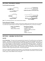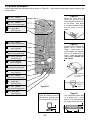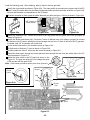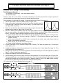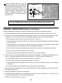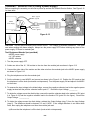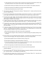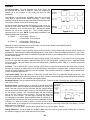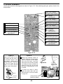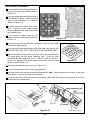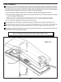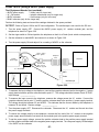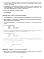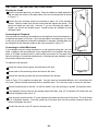
1
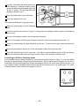
PULSE/TONE TELEPHONE KIT
MODEL AK-700/PT-323K
Assembly and Instruction Manual
SECTION 1 - INTRODUCTION
The Model AK-700 / PT-323K is a push button electronic telephone kit. Your telephone is equipped with the
following features: A) a tone/pulse switch, B) automatic redial (for pulse dialer) of up to 32 digits, C) a ringer
turn off switch, and D) four neon bulbs to give a visual indication that the telephone is ringing. The kit is built up
in three sections: 1) Ringer, 2) Transmit-Receive, and 3) Dialer. As each section is added, its function is
explained and tests are run to demonstrate its operation.
FCC regulations do not allow the Model AK-700 / PT-323K Telephone to be connected to the telephone network
unless it has been either assembled under the supervision of an instructor or been tested by Elenco.
SECTION 2 - FCC REQUIREMENTS
For the last several years, the Federal Communications Commission (FCC) has provided the standards for the
protection of the telephone network from harm caused by the connection of terminal equipment. The rules
established require that all terminal equipment, such as your telephone, be registered with the FCC. The FCC
registration number of your telephone is GXA3PP-19545-TE-E.
If trouble is experienced, the telephone must be removed from the telephone network to determine if it is
malfunctioning. If it is malfunctioning, the telephone must not be reconnected to the telephone network until
repairs are made. Repairs should be made by Elenco. To arrange for repairs, contact Elenco at the address
given on the back of this manual.
SECTION 3 - GENERAL DESCRIPTION
The primary purpose of the telephone is to transmit and receive voice signals allowing two people with
telephones to communicate with each other. To be of practical value, the telephone must be connected to a
switching network capable of connecting each telephone to many other telephones. To accomplish this switching,
each subscriber telephone is connected to the telephone company’s Central Office by two wires referred to as
the “Local Loop”. A simplified diagram of this connection is shown in Figure 3-1. The Tip and Ring designation
of the + and – leads come from the days of the manual switchboard. The tip of the plug the operator used to
connect telephones carried the (+) lead and the ring immediately behind the tip carried the (–) lead.
When a subscriber wishes to place a call, they merely pick up the telephone and a small current flows in the
local loop. This current picks a relay in the Central Office indicating that service is being requested. When the
Central Office is ready to accept the number being called, a dial tone is sent to the calling telephone. The dial
pulses, or tones, then signal to the Central Office the number of the telephone being called. A path is then
established to that telephone. This path may be a simple wire connection to a telephone connected to the same
Central Office or it may go via wire, microwave link, or satellite to a telephone connected to a distant Central
Office. To signal the incoming call, a ringing signal is placed on the local loop of the called telephone. The
ringing signal is a 90 VAC 20Hz signal superimposed on the 48VDC present on the local loop. A ringing tone
is also sent to the calling telephone. When the called party picks up the telephone, voice communication is
established.
-1-
The Rotary Dial Telephone
A simplified schematic diagram of the
traditional rotary dial telephone is shown in
Figure 3-2. The major parts of this telephone
are explained below. Your kit is a newer
electronic type telephone. When you build
your telephone in Section 6, you will notice
several differences between the traditional and
electronic type telephones.
Hook Switch
When the hook switch is open (on hook) no
current flows in the local loop. The 48VDC
from the battery in the Central Office appears
on the tip and ring input to the telephone set.
When the receiver is lifted, the hook switch
closes and a current of about 20 to 120mA
flows in the local loop. The resistance of the
local loop drops the voltage at the telephone to
about 6 volts. The current picks a relay in the
Central Office which tells other equipment
there that service is being requested. When
the Central Office is ready to accept the
number being called, a dial tone is sent to the
calling telephone. The dial tone stops when
the first digit is dialed.
Figure 3-1
Figure 3-2
Dialer
There are two types of dialers, pulse and tone.
Pulse Dialer
Pulse dialing is accomplished by the familiar rotary dial shown in Figure 3-2. The dial is rotated to the stop and
then released. A spring in the dialer returns the dial to its null position. As the dial returns, the dial switch (S2)
opens and closes at a fixed rate. This switch is in series with the hook switch. Opening the switch interrupts the
current in the local loop. A series of current pulses is thus sent out on the local loop as shown in Figure 3-3. The
number of pulses sent corresponds to the digit dialed. Dialing “0” sends ten pulses. The dial pulses are sent at
a rate of 10 pulses per second (100 ms. between pulses). Each pulse consists of a mark interval (loop current)
and a space interval (no loop current). In America, the mark interval is 40 ms. and the space interval is 60 ms.
giving a mark/space ratio of 40/60. In Europe, the mark space ratio is usually 33/67.
Figure 3-3
-2-
Tone Dialer
Tone dialing is accomplished with a keyboard of 12
keys arranged in 4 rows and 3 columns. As seen in
Figure 3-4, low frequencies of 697, 770, 852 and
941 are associated with rows R1 through R4 and
high frequencies of 1209, 1336 and 1477Hz are
associated with columns C1 through C3. To send
each digit, two frequencies are sent to the Central
Office simultaneously. For this reason, this method
of dialing is referred to as Dual Tone Multifrequency
(DTMF). The different frequencies are generated by
connecting a capacitor to different taps of a
transformer to establish a resonant circuit of the
correct frequency. Each of the 3 keys of row 1 are
mechanically connected to switch SR1. Similarly,
each of the other rows and columns are connected
to their corresponding switch. Thus, pressing any
key closes two switches and generates two
frequencies. Pressing a 6 for example, closes
switches SR2 and SC3 and generates 770 and
1477Hz.
Figure 3-4
Transmitter
The Transmitter consists of a metal diaphragm and a metal case insulated from each other as shown in Figure 3-5.
The case is filled with carbon granules. When you speak into the transmitter, the sound waves of your voice strike
the diaphragm and causes it to vibrate. This causes the carbon granules to compress and expand. When
compressed, the resistance of the carbon granules is less than when expanded. The change of resistance causes
a corresponding change in the current. The current thus varies in step with the sound waves of your voice.
Figure 3-5
-3-
Receiver
There are several different types of receivers. In principle, they
work the same as the speakers in your radio and TV. The speaker
consists of a small coil attached to a diaphragm. The coil is
mounted over a permanent magnet as shown in Figure 3-6. Coil
current in one direction causes the coil and diaphragm to be
repelled from the permanent magnet. Coil current in the other
direction causes the coil and diaphragm to be attracted to the
permanent. If a current of audio frequency is sent through the
coil, the diaphragm vibrates and generates sound waves in step
with the current. Thus, if the current from the transmitter is sent
through the coil, the sound produced will duplicate the sound
striking the transmitter.
Ringer
As shown in Figure 3-2, the ringer is connected across the tip
and ring inputs in series with a capacitor to block the 48VDC.
The ringer consists of a permanent magnet attached to an
armature as shown in Figure 3-7. When an alternating current
of 20Hz is passed through the coils, the armature is alternately
attracted to one coil and then the other. The hammer attached
to the armature thus strikes one bell and then the other to
produce the ringing sound.
Figure 3-6
Induction Coil / Balance Network
When transmitting and receiving is done over the same two
wires, the problem arises that current from the transmitter flows
through the receiver. The speaker then hears their own voice
from the receiver. This is called sidetone. Too much sidetone
may be objectionable to the speaker and cause them to speak
too softly. A small amount of sidetone is desirable to keep the
telephone from sounding dead.
Figure 3-7
The induction coil and balance network limit the sidetone. The impedance of the balance network shown in
Figure 3-2 approximately matches the impedance of the local loop. Thus, about half of the current from the
transmitter flows through L1 and the local loop and the other half flows through L2 and the balance network. The
currents in L1 and L2 induce voltages in L3 of opposite polarity which limits the voltage across the receiver to an
acceptable level. When receiving a signal from the local loop, the currents in L1 and L2 induce voltages in L3 of
the same polarity. These voltages combine to drive the receiver.
-4-
SECTION 4 - PARTS LIST
If any parts are missing or damaged, see instructor or bookstore. DO NOT contact your place of purchase as
they will not be able to help you.
Contact Elenco Electronics (address/phone/e-mail is at the back of this manual) for additional assistance, if
needed.
* BAG 1 *
Resistors (For identifying values, refer to page 8).
QTY
1
1
1
4
2
3
4
4
2
1
SYMBOL
R18
R19
R7
R12, R13, R15, R20
R5, R23
R16, R17, R22
R1 - R4
R6, R9, R11, R21
R10, R14
R8
DESCRIPTION
10Ω 5% 1/4W
120Ω 5% 1/4W
2.2kΩ 5% 1/4W
3.3kΩ 5% 1/4W
10kΩ 5% 1/4W
15kΩ 5% 1/4W
47kΩ 5% 1/4W
100kΩ 5% 1/4W
150kΩ 5% 1/4W
1MΩ 5% 1/4W
COLOR CODE
brown-black-black-gold
brown-red-brown-gold
red-red-red-gold
orange-orange-red-gold
brown-black-orange-gold
brown-green-orange-gold
yellow-violet-orange-gold
brown-black-yellow-gold
brown-green-yellow-gold
brown-black-green-gold
PART #
121000
131200
142200
143300
151000
151500
154700
161000
161500
171000
Diodes
QTY
4
2
1
1
SYMBOL
D1 - D4
D5, D6
D8
D7
VALUE
1N4004 or 1N4007
1N4148
55C2V7/1N5223 2.7V
55C4V7/1N5230 4.7V
DESCRIPTION
Diode
Diode
Zener Diode
Zener Diode
PART #
314004
314148
315223
315230
* BAG 2 *
Capacitors (For identifying values, refer to page 8).
QTY
2
1
1
1
1
1
1
3
SYMBOL
C10, C11
C5
C2
C8
C7
C1
C6
C3, C4, C9
VALUE
30pF
300pF
.01µF
.02µF
.04µF
.47µF
1µF 50V
47µF 10V
DESCRIPTION
Discap (30)
Discap (300)
Discap (.01 or 103)
Discap (.02 or 203)
Discap (.04 or 403)
Mylar (474/470N)
Electrolytic (Lytic)
Electrolytic (Lytic)
PART #
213010
223017
241031
242010
240417
254710
261047
274742
* BAG 3 *
QTY
1
1
1
2
1
1
4
1
SYMBOL
Q2
Q3
Q4
Q1, Q5
IC1
X
LP1 - LP4
IC1
VALUE
2N5401
2N5551
9013H
9014C
HM9102
DESCRIPTION
Transistor PNP
Transistor NPN
Transistor NPN
Transistor NPN
Integrated Circuit (IC)
Resonator 3.58MHz
Neon Bulb
IC Socket 18-pin
-5-
PART #
325401
325551
329013
329014
339102
560358
585021
664018
* BAG 4 *
QTY
1
2
2
2
DESCRIPTION
Switch SPDT (Hook) (S2)
Switch SPDT (S1, S3)
Screw 1/4” (Keyboard)
Screw 5/8” (Case)
PART #
541108
541109
642237
642477
* BAG 5 *
QTY
1
1
1
1
1
1
DESCRIPTION
Microphone (MIC) (without leads)
Buzzer (B)
Modular Jack
Label Telephone # (2 parts)
Microphone Pad
Buzzer Pad
PART #
568001
595223
621019
721006
780126
780125
* BAG 6 *
QTY DESCRIPTION
1 Battery Snap 9V
1 Wire 22AWG Solid Yellow 6”
*
1 Wire 26AWG Stranded Red 2”
1 Wire 26AWG Stranded Red 4”
4 Wire 26AWG Stranded Gray 3”
1 Wire 26WAG Stranded Orange 2”
1 Ribbon Cable 1” (9 wires)
1 Solder
* The Wire 22AWG Solid Yellow 6” is not used.
PART #
590098
814420
834520
834521
834530
834523
879009
9ST4
* BAG 7 *
QTY
1
1
1
DESCRIPTION
PC Board Keypad
Push Button Set (12)
Contact Pad Keypad
PART #
517028
540103
789032
* MAIN BAG *
QTY
1
1
1
1
1
1
1
1
1
1
DESCRIPTION
PC Board Main
Speaker (SP)
Case Top Clear
Case Bottom Clear
Cradle Clear
Hook Button Clear
Label Dial
Speaker Pad
Telephone Cord
Manual
PART #
517027
590102
623300
623400
626001
626040
721027
780127
860900
753700
-6-
PARTS IDENTIFICATION
BAG 1
Resistor
BAG 2
Diodes
Capacitors
Epoxy
Electrolytic
Glass
BAG 3
Transistor
BAG 4
Integrated Circuit (IC)
Resonator
Disc
Mylar
IC Socket
Switch SPDT
(S1, S3)
Switch SPDT
(Hook) (S2)
Neon Bulb
5/8” Screw
Modular Jack
BAG 5
Microphone
Buzzer
Microphone Pads
Buzzer Pad
1/4” Screw
BAG 6
Ribbon Cable
Solder
Wire
Label & Cover
Battery Snap
BAG 7
Keypad PC Board
Push Button Set (12)
Contact Keypad
MAIN BAG
Main PC Board
Speaker
Pad
Clear Top Case
Clear Cradle
Clear Hook
Button
Telephone Cord
Speaker (SP)
Clear Bottom Case
Label
Dial
-7-
IDENTIFYING RESISTOR VALUES
Use the following information as a guide in properly identifying the value of resistors.
BAND 1
1st Digit
Color
Black
Brown
Red
Orange
Yellow
Green
Blue
Violet
Gray
White
Multiplier
BAND 2
2nd Digit
Digit
0
1
2
3
4
5
6
7
8
9
Color
Black
Brown
Red
Orange
Yellow
Green
Blue
Violet
Gray
White
Resistance
Tolerance
Color
Multiplier
Black
1
Brown
10
Red
100
Orange
1,000
Yellow
10,000
Green
100,000
Blue
1,000,000
Silver
0.01
Gold
0.1
Digit
0
1
2
3
4
5
6
7
8
9
Color
Silver
Gold
Brown
Red
Orange
Green
Blue
Violet
Tolerance
+10%
+5%
+1%
+2%
+3%
+0.5%
+0.25%
+0.1%
BANDS
1
2
Multiplier
Tolerance
IDENTIFYING CAPACITOR VALUES
Capacitors will be identified by their capacitance value in pF (picofarads), nF (nanofarads), or µF (microfarads). Most
capacitors will have their actual value printed on them. Some capacitors may have their value printed in the following
manner. The maximum operating voltage may also be printed on the capacitor.
Multiplier
For the No.
0
1
2
3
Multiply By
1
10
100
1k
4
5
8
10k 100k 0.01
10µF 16V
First Digit
9
0.1
Note: The letter “R” may be used at times
to signify a decimal point; as in 3R3 = 3.3
Second Digit
Multiplier
103K
Tolerance
100V
The letter M indicates a tolerance of +20%
The letter K indicates a tolerance of +10%
The letter J indicates a tolerance of +5%
Maximum Working Voltage
The value is 10 x 1,000 = 10,000pF or .01µF 100V
METRIC UNITS AND CONVERSIONS
Abbreviation
p
n
µ
m
–
k
M
Means
pico
nano
micro
milli
unit
kilo
mega
Multiply Unit By
.000000000001
.000000001
.000001
.001
1
1,000
1,000,000
Or
10-12
10-9
10-6
10-3
100
103
106
-8-
1,000 pico units = 1 nano unit
1,000 nano units = 1 micro unit
1,000 micro units = 1 milli unit
1,000 milli units
= 1 unit
1,000 units
1,000 kilo units
= 1 kilo unit
= 1 kilo unit
CONSTRUCTION
Introduction
The most important factor in assembling your Tone/Pulse Telephone Kit is good soldering techniques. Using
the proper soldering iron is of prime importance. A small pencil type soldering iron of 25 - 40 watts is
recommended. The tip of the iron must be kept clean at all times and well tinned.
Safety Procedures
• Wear eye protection when soldering.
• Locate soldering iron in an area where you do not have to go around it or reach over it.
• Do not hold solder in your mouth. Solder contains lead and is a toxic substance. Wash your hands
thoroughly after handling solder.
• Be sure that there is adequate ventilation present.
Assemble Components
In all of the following assembly steps, the components must be installed on the top side of the PC board unless
otherwise indicated. The top legend shows where each component goes. The leads pass through the
corresponding holes in the board and are soldered on the foil side.
Use only rosin core solder of 63/37 alloy.
DO NOT USE ACID CORE SOLDER!
What Good Soldering Looks Like
Types of Poor Soldering Connections
A good solder connection should be bright, shiny,
smooth, and uniformly flowed over all surfaces.
1.
Solder all components from
the copper foil side only.
Push the soldering iron tip
against both the lead and
the circuit board foil.
1. Insufficient heat - the
solder will not flow onto the
lead as shown.
Soldering Iron
Component Lead
Foil
Soldering iron positioned
incorrectly.
Circuit Board
2.
3.
4.
Apply a small amount of
solder to the iron tip. This
allows the heat to leave the
iron and onto the foil.
Immediately apply solder to
the opposite side of the
connection, away from the
iron.
Allow the heated
component and the circuit
foil to melt the solder.
Allow the solder to flow
around the connection.
Then, remove the solder
and the iron and let the
connection cool.
The
solder should have flowed
smoothly and not lump
around the wire lead.
Rosin
2. Insufficient solder - let the
solder flow over the
connection until it is
covered. Use just enough
solder
to
cover
the
connection.
Soldering Iron
Solder
Foil
Solder
Gap
Component Lead
Solder
3. Excessive solder - could
make connections that you
did not intend to between
adjacent foil areas or
terminals.
Soldering Iron
Solder
Foil
4. Solder bridges - occur
when solder runs between
circuit paths and creates a
short circuit. This is usually
caused by using too much
solder.
To correct this,
simply drag your soldering
iron across the solder
bridge as shown.
Here is what a good solder
connection looks like.
-9-
Soldering Iron
Foil
Drag
SECTION 5 - EQUIPMENT NEEDED
Tools Needed (not provided)
Phillips Screwdriver (small point size)
Long Nose Pliers
Diagonal Cutters
Small Pencil Type Soldering Iron
of 25 - 40 Watts
Note: The following equipment is not included unless indicated.
Testing Equipment Needed:
The test procedures are written for using AC and DC power supplies (only for final ringer test) or a 9V battery.
If you don’t have a power supply for the ringer, transmit-receive and dialer tests, you can use a 9V battery.
Using a 9 Volt Battery
Using Power Supplies
• 9 volt battery
• Battery Snap (Included)
• 9 - 48VDC Power Supply
• Resistor 1kΩ 5W
• Voltmeters 48VDC and 50VAC
• Oscilloscope
• Variac
• Isolation Transformer
SECTION 6 - ASSEMBLY INSTRUCTIONS
RINGER
Circuit Description - The ringer circuit is connected directly across the Tip and Ring inputs (see Schematic
Diagram). The capacitor C1 blocks the 48VDC that is present on the inputs when the phone is on the hook. To
signal an incoming call, the Central Office places a 90VAC 20Hz signal on top of the 48VDC. If the ringer switch
(S1) is closed, transistor Q1 conducts during the 1/2 cycle that the Ring terminal is positive. The collector to
emitter voltage is applied to the buzzer causing it to change dimensions. The feedback lead is connected to the
base of transistor Q1 through resistor R7 causing the circuit to oscillate at about 3kHz. There is no oscillation
during the negative portion of the 20Hz signal. The buzzing sound is thus produced by the buzzer changing
dimensions a 3kHz during the positive portion of the 20Hz ringing signal.
The four neon bulbs LP1 through LP4 and resistors R1, R2, R3 and R4 are also connected across the Tip and
Ring inputs. When the ringing signal causes the voltage across the bulbs to exceed about 100 volts, the bulbs
conduct, giving a visual indication of the incoming call.
-10-
PC BOARD ASSEMBLY
Identify and install the following parts as shown in Figure 6-1. After soldering each part, place a check in the
box provided.
Figure A
R3 - 47kΩ Resistor
(yellow-violet-orange-gold)
Mount the neon bulb as
shown with the bulb in the
same direction as marked on
the PC board. Give about
a 1/8” space between the bulb
and the holes in the PC
board.
R4 - 47kΩ Resistor
(yellow-violet-orange-gold)
LP4 - Neon Bulb
LP3 - Neon Bulb
(see Figure A)
1/8”
R5 - 10kΩ Resistor
(brown-black-orange-gold)
Figure B
Mount the mylar capacitor flat
against the PC board as
shown. Leave about 1/4”
space between the capacitor
and the PC board holes as
shown. Solder and twist the
leads together. DO NOT CUT
THE LEADS.
C1 - .47µF Mylar Cap. (474)
(see Figure B)
R6 - 100kΩ Resistor
(brown-black-yellow-gold)
Q1 - 9014C Transistor
(see Figure C)
R7 - 2.2kΩ Resistor
(red-red-red-gold)
1/4”
R14 - 150kΩ Resistor
(brown-green-yellow-gold)
LP1 - Neon Bulb
(see Figure A)
Note: Make sure
that these leads
do not touch.
R1 - 47kΩ Resistor
(yellow-violet-orange-gold)
T - Jumper Wire
R - Jumper Wire
(see Figure D)
R2 - 47kΩ Resistor
(yellow-violet-orange-gold)
LP2 - Neon Bulb
(see Figure A)
Twist the
leads.
Figure 6-1
Figure C
Figure D
Mount the transistor with the
flat side in the same direction
as marked on the PC board.
Use a discarded resistor lead
for a jumper wire. Leave
about a 1/16” space between
the jumper and the PC board.
1/16”
1/16”
1/4”
-11-
Install the following parts. After soldering, place a check in the box provided.
Identify the ringer switch as shown in Figure 6-2a. The ringer switch is mounted on the copper side of the PC
board. Insert the switch tabs into the holes provided and solder the three terminals as shown in Figure 6-2b.
Be sure that the switch is perpendicular to the PC board.
To anchor the switch in place, grasp the switch tabs with your pliers and give a 1/8 turn as shown in Figure 6-2c.
OFF Position of
Ringer Switch
Figure 6-2a
Figure 6-2b
Figure 6-2c
Identify the telephone cord. Solder the red wire to the ring jumper and the green wire to the tip jumper as
shown in Figure 6-3.
Identify the buzzer and buzzer pad. Use three 2” wires of different color (red, orange, and gray) to connect
the buzzer to the PC board. Identify the red and orange wire and cut a 2” piece of wire off of the 3” gray wire.
If needed, strip 1/8” of insulation off of each end.
Tin the buzzer with solder in the locations shown in Figure 6-3a.
Tin both ends of the three 2” wires as shown in Figure 6-3b.
Carefully solder the three 2” wires onto the buzzer as shown in Figure 6-3.
Thread the three wires through the buzzer pad and then through the hole from the solder side of the PC
board as shown in Figure 6-3.
Solder the three wires to the PC board as shown in the
Figure 6-3. The gray wire goes to B1, the orange wire goes
to B2 and the red wire goes to B3.
Note: If the buzzer pad has a center piece, then remove it.
Solder
Tinned
Points
Buzzer
Wire
Solder Iron
Red
Figure 6-3a
Figure 6-3b
Orange
Gray
Telephone Cord
Buzzer
Pad
Red
Green
Figure 6-3
-12-
If you have a 9VDC power supply, skip to the Ringer Test on page 14.
RINGER TEST (Using a 9 Volt Battery)
Test Equipment Needed
• 9 volt battery (not provided). Use a fresh alkaline battery.
• 9 volt battery snap.
Testing is done with a 9 volt battery. To conserve the battery, it should be connected for only short periods of
time and disconnected whenever tests are not actually being performed.
Since capacitor C1 blocks the DC voltage, it is shorted for this test (Figure B on page 11).
1. Set the ringer switch to the OFF position (refer to Figure 6-2b).
Type A
Type B
2. Check to see which modular jack, type A or B, has been included in your kit.
If you have type A, then use Figure 6-4a for testing. If you have type B, then
use Figure 6-4b for testing.
3. Solder the red and black wires from the 9 volt battery snap to the wires of the
Green
Red Red
Green
modular jack as shown in Figure 6-4a or Figure 6-4b.
4. Put the 9V battery into the battery snap. Be sure that the telephone cord is plugged into your modular jack.
Set the ringer switch to ON (toward the center of the PC board). You should hear a 3kHz tone from the
buzzer. If no tone is heard, unplug the telephone cord from the modular jack and:
a) Check that the battery snap is connected with the right polarity as shown in Figure 6-4a or Figure 6-4b.
b) Check that the buzzer is wired as shown in Figure 6-3. Check that the telephone cord wires are
soldered correctly.
c) Check that transistor Q1 is a 9014C and is mounted with the emitter, base and collector leads as
shown in the assembly instructions.
d) Check that R5, R6 and R7 are the correct values.
e) Check for bad solder joints and solder bridges.
5. Put the ringer switch to OFF (toward the edge of the PC board). The 3kHz tone should stop. Put the ringer
switch back to ON.
6. Unplug the telephone cord from the modular jack. Cut the leads from C1 (see Figure B on page 11). This
removes the short from capacitor C1.
7. With the ringer switch ON, reconnect the telephone cord to the modular jack. Since the capacitor now blocks
the DC, no tone is heard from capacitor C1.
8. Unplug the telephone cord from the modular jack.
9. Peel the backing off of the buzzer side of the buzzer pad and place it on the buzzer as shown in Figure 6-6a.
The pad goes directly on top of the three buzzer wires. Peel the second backing off of the buzzer mounting
pad and stick the pad onto the solder side of the PC board as shown in Figure 6-6b. Note: When mounting,
be sure that you allow room for the Pulse/Tone Switch and Hook Switch.
10. Continue to the Transmit-Receive Section on page 15.
Red
Black
Red
Black
Red
Green
Green
Red
Type A
Figure 6-4a
Modular Jack
Type B
Figure 6-4b
Modular Jack
-13-
RINGER TEST (Using a Power Supply)
Test Equipment Needed (not provided)
• 9VDC power supply.
Since capacitor C1 blocks the DC voltage, it is shorted for this test (Figure B on page 11).
1. Set the ringer switch to the OFF position (refer to Figure 6-2b).
2. Check to see which modular jack, type A or B, has been included in your kit.
If you have type A, then use Figure 6-5a for testing. If you have type B, then
use Figure 6-5b for testing.
3. Connect the modular jack wires to the terminals on the power supply (as
shown in Figure 6-5a or Figure 6-5b.
Type A
Type A
Green
Type B
Red Red
Green
Figure 6-5a
Green
9VDC
Power Supply
+
Modular Jack
Telephone Cord
Red
Type B
Figure 6-5b
Red
9VDC
Power Supply
+
Modular Jack
Telephone Cord
Green
Perform the following Ringer tests:
4. Turn on the power supply. Set the ringer switch to ON (toward the center of the PC board). You should hear
a 3kHz tone from the buzzer. If no tone is heard, unplug the telephone cord from the modular jack and:
a) Check that the power supply is connected with the right polarity as shown in Figure 6-5a or Figure 6-5b.
b) Check that the buzzer is wired as shown in Figure 6-3. Check that the telephone cord wires are
soldered correctly.
c) Check that transistor Q1 is a 9014 and is mounted with the emitter, base and collector leads as shown
in the assembly instructions.
d) Check that R5, R6 and R7 are the correct values.
e) Check for bad solder joints and solder bridges.
5. Put the ringer switch to OFF (toward the edge of the PC board). The 3kHz tone should stop. Put the ringer
switch back to ON.
6. Turn the power supply OFF. Reconnect the power supply with the wire to the positive terminal and the wire
to the negative terminal reversed. This simulates the negative portion of the ringing signal. Turn the power
supply ON. No tone should be heard from the buzzer.
7. Have your instructor inspect the ringer circuitry and verify test performed.
Instructor’s Approval: ___________________________
8. Unplug the telephone cord from the modular jack. Cut the leads from C1 (Figure B on page 11). This
removes the short from capacitor C1.
9. With the ringer switch ON, reconnect the circuit as shown in Figure 6-5a or Figure 6-5b and plug the telephone
cord to the modular jack. Since the capacitor now blocks the DC, no tone is heard from capacitor C1.
10. Turn the power supply OFF and disconnect the power supply from the modular jack wires.
-14-
11. Unplug the telephone cord from the modular jack.
12. Peel the backing off of the buzzer side of the buzzer pad and place it on the buzzer as shown in Figure 6-6a.
The pad goes directly on top of the three buzzer wires. Peel the second backing off of the buzzer mounting
pad and stick the pad onto the solder side of the PC board as shown in Figure 6-6b. Note: When mounting,
be sure that you allow room for the Pulse/Tone Switch and Hook Switch.
13. Continue to the Transmit-Receive Section.
Buzzer Pad
Location of Ringer Switch
Buzzer
Location of
Hook Switch
Location of
Pulse/Tone Switch
Figure 6-6a
Figure 6-6b
TRANSMIT-RECEIVE
Circuit Description - The Tip and Ring inputs are fed to a diode bridge made up of diodes D1 through D4 (see
schematic diagram). The bridge insures that a positive voltage is fed to the telephone circuit regardless of the
polarity of the input. This is done to protect the integrated circuit and other components that may be damaged
by a reversal of polarity.
When the hook switch is not depressed, the telephone is ready to transmit and receive. The incoming signal
from the Central Office is sent via R20 and C6 to the speaker amplifier made up of transistor Q5. This amplifier
drives the speaker.
Transmission begins when you speak into the microphone. The microphone used is an electret type. This type
of microphone is made up of a capacitor with a dielectric material which holes a permanent electric charge.
Sound waves striking a plate of this capacitor cause the plate to vibrate and thus generate a small voltage
across the capacitor. This voltage is amplified by a Field Effect Transistor (FET) mounted inside the microphone.
The signal from the microphone is then amplified and sent to the Central Office via the local loop. A portion of
the signal is also sent to the speaker amplifier to provide the desired sidetone.
-15-
PC BOARD ASSEMBLY
Identify and install the following parts as shown in Figure 6-7. After soldering each part, place a check in the
box provided.
Q5 - 9014 Transistor
(see Figure C)
C6 - 1µF Lytic Capacitor
(see Figure F)
R19 - 120Ω Resistor
(brown-red-brown-gold)
R20 - 3.3kΩ Resistor
(orange-orange-red-gold)
R21 - 100kΩ Resistor
(brown-black-yellow-gold)
C4 - 47µF Lytic Capacitor
(see Figure F)
C9 - 47µF Lytic Capacitor
(see Figure F)
Q4 - 9013 Transistor
(see Figure C)
D8 - 2.7V Zener Diode
(see Figure E)
R16 - 15kΩ Resistor
(brown-green-orange-gold)
R18 - 10Ω Resistor
(brown-black-black-gold)
Q3 - 2N5551 Transistor
(see Figure C)
C7 - .04µF Discap (.04 or 403)
R10 - 150kΩ Resistor
(brown-green-yellow-gold)
R15 - 3.3kΩ Resistor
(orange-orange-red-gold)
R12 - 3.3kΩ Resistor
(orange-orange-red-gold)
R17 - 15kΩ Resistor
(brown-green-orange-gold)
Q2 - 2N5401 Transistor
(see Figure C)
C5 - 300pF Discap (300)
R11 - 100kΩ Resistor
(brown-black-yellow-gold)
D2 - 1N4004 Diode
(see Figure E)
D4 - 1N4004 Diode
(see Figure E)
Figure 6-7
D1 - 1N4004 Diode
(see Figure E)
Figure F
D3 - 1N4004 Diode
(see Figure E)
Electrolytics have a polarity
marking indicating the (–)
lead.
The PC board is
marked to show the lead
position. Mount the capacitor
laying down on the PC board
as shown.
Figure E
Mount the diodes with the
band marked on them in the
same direction marked on the
PC board.
Polarity Marking
1/16”
Band
-16-
+
Install the following parts. After each step is completed, place a check mark in the box.
Identify two wires (4” red and 3” gray), microphone and microphone pad. Cut the 4” red wire down
to 2” and the 3” gray wire to 2”. Use the 2” red and 2” gray stranded wires and strip 1/8” of insulation
off of each end. Identify the microphone. Bend the wires and very carefully solder the wires to the
microphone as shown in Figure 6-8.
Bend
Wire
Peel the backing off of one side of the microphone pads and place them onto the microphone as shown in
Figure 6-9a.
Peel the second backing off of the microphone pads and thread the wires through the hole in the PC board
from the solder side as shown in Figure 6-9b. Solder the red wire to the hole marked MIC on the PC board
and the gray wire to the hole marked GND on the PC board. Place the microphone on the PC board on the
solder side as shown in Figure 6-9c. DO NOT contact the microphone with the buzzer.
Red Wire
+
Red Wire
Gray Wire
Gray
Wire
Figure 6-8
Figure 6-9a
Figure 6-9b
Figure 6-9c
Identify the hook switch. The hook switch mounts to the copper side of the PC board. Insert the switch tabs
into the mounting holes (see Figure 6-10a) and twist the tabs 1/8 of a turn as was done with the ringer switch.
Solder the switch’s contacts to the PC board using two pieces of discarded resistor leads and a 3” gray
stranded wire as shown in Figure 6-10b.
Hook Switch
Hook Switch
Resistor
Lead
Foil Side of
PC Board
Foil Side of
PC Board
P3
P2
Figure 6-10a
3” Gray Wire
-17-
Figure 6-10b
Resistor
Lead
P1
Identify the speaker with pad, 3” gray wire,
and the second half of the 4” red wire (the first
half was used for the microphone). Cut a 2”
piece from the 3” gray wire and strip 1/8” of
insulation off of both ends. Solder the red
wire to the speaker + and the gray wire to the
speaker – as shown in Figure 6-11. Solder
the red wire to SP+ on the PC board and the
gray wire to SP–.
Figure 6-11
Red Wire
+
Gray Wire
Speaker Pad
If you have a 48VDC power supply, skip to the Transmit/Receive Test on page 19.
TRANSMIT - RECEIVE TESTS (Using a 9 volt battery)
Before completing the assembly, we will want to power up and test the Transmit-Receive Section.
1. Connect the telephone cord to the modular jack with the battery snap as shown in Figure 6-4a or 6-4b.
2. Put your ear to the receiver and depress and release the hook switch. You should hear a click when the switch
is depressed. If you do not hear the click, then unplug the telephone cord from the modular jack and:
a) Check that the speaker wires are connected as shown in Figure 6-11.
b) Check diodes D1 through D4 and D8. Be sure that they are installed according to the polarity markings
on the PC board.
c) Check transistors Q2, Q3, Q4 and Q5. Be sure that they are the proper type and that the emitter, base
and collector leads are mounted as shown in the assembly instructions.
d) Check that the resistors just installed are the correct values as shown in the assembly instructions.
e) Check the hook switch and the wires to the PC board.
f) Check the components just installed for bad solder joints and solder bridges.
3. Put the receiver to your ear and gently tap or scratch the microphone. You should hear tapping from the
receiver. Unplug the telephone cord from the modular jack. If you do not hear the tapping, then:
a) Check that the speaker wires are connected as shown in Figure 6-11.
b) Check that the microphone is connected as shown in Figure 6-9.
c) Check that transistors Q2 through Q5 are the proper type and are mounted as shown in the assembly
instructions.
d) Check the components just installed for bad solder joints and solder bridges.
4. Reverse the battery snap leads to the wires of the modular jack, plug the telephone cord to the modular jack
and repeat steps 2 and 3.
5. Unplug the telephone cord from the modular jack.
6. To avoid breaking the speaker wires, unsolder them from the PC board (see Figure 6-11). Leave the wires
connected to the speaker. They will be reconnected later.
7. Continue to the Dialer Section on page 21.
-18-
TRANSMIT - RECEIVE TESTS (Using a power supply)
Before completing the assembly, we will want to power up and test the Transmit-Receive Section. See Figure 6-12
for these tests.
B
Green - Type A
Red - Type B
Telephone Cord
A
48VDC
Power Supply
+
Modular Jack
Red - Type A
Green - Type B
C
1kΩ 5W Resistor
Type A
Green
Figure 6-12
Type B
Red
Red
Green
CAUTION: This test and succeeding tests involve 48VDC. This voltage is potentially hazardous. Use great
care when working with these voltages. Always turn the power supply OFF before touching any wires on the
power supply, PC board or modular jack.
Test Equipment Needed (not provided)
• 48VDC power supply
• 1kΩ 5W resistor
• 48VDC voltmeter
1. Turn the power supply OFF.
2. Solder one side of the 1kΩ 5W resistor to the wire from the modular jack as shown in figure 6-12
3. Connect the other side of the resistor and the other wire from the modular jack to the 48VDC power supply
as shown in Figure 6-12.
4. Plug the telephone cord into the modular jack.
5. Set the voltmeter to read 48VDC and connect as shown in the Figure 6-12. Position the PC board so that
the telephone is off the hook (hook switch not depressed). Turn the power supply ON and adjust it for 48VDC
on the meter.
6. To measure the input voltage to the diode bridge, connect the negative voltmeter lead to the negative power
supply terminal and the positive voltmeter lead to point “C”. Record the Input Voltage: _________
7. To obtain the voltage across the diode bridge, connect the positive voltmeter lead to the cathode of D1 (point
A in Figure 6-12) and the negative voltmeter lead to the anode of D2 (point B in the figure). Record the
Output Voltage: ___________
8. To obtain the voltage across the diode bridge, subtract the Output Voltage (step 7) from the Input Voltage
(step 6). The difference should be between 1.3 and 1.9VDC. If the voltage difference is not within these
limits, then unplug the telephone cord from the modular jack and:
a) Be sure that the telephone is off the hook (hook switch not depressed).
-19-
c) Check transistors Q2, Q3, Q4 and Q5. Be sure that they are the proper type and that the emitter, base
and collector leads are in the correct holes as shown in the assembly instructions.
d) Check that the resistors just installed are the correct values as shown in the assembly instructions.
e) Check the components just installed for bad solder joints and solder bridges.
f) Check the hook switch and wires to the PC board.
9. Turn the power supply OFF. Disconnect the voltmeter. Disconnect the 1kΩ resistor and the red wire from
the power supply terminals.
10. To reverse the voltage polarity to the diode bridge, connect the free end of the 1kΩ resistor to the negative
power supply terminal and the red wire from the modular jack to the positive power supply terminal.
11. To set the power supply voltage, connect the positive voltmeter lead to the positive terminal of the power
supply and the negative voltmeter lead to the negative terminal of the power supply. Turn the power supply
ON and adjust it to 48VDC on the voltmeter.
12. To again measure the input voltage to the diode bridge, connect the positive voltmeter lead to the positive
power supply terminal and the negative voltmeter lead to point “C”. Record the Input Voltage: __________
13. To measure the output voltage of the diode bridge, connect the positive voltmeter lead to the cathode of D1
(point A in Figure 6-12) and the negative voltmeter lead to the anode of D2 (point B in Figure 6-12). Record
the Output Voltage: ___________
14. To obtain the voltage across the diode bridge, subtract the Output Voltage (step 13) from the input voltage
(step 12). The difference should be between 1.3 and 1.9VDC. If the voltage difference is not within these
limits, then unplug the telephone cord from the modular jack and:
a) Be sure that the telephone is off the hook (hook switch not depressed).
b) Check diodes D1 through D4. Be sure that they are installed according to the polarity markings on the
PC board.
15. Put the receiver to your ear and gently tap the microphone. You should hear the tapping from the receiver.
If you do not hear the tapping, then unplug the telephone cord from the modular jack and:
a) Check that the speaker wires are connected as shown in Figure 6-11.
b) Check that the microphone is connected as shown in Figure 6-9.
c) Check that transistors Q2 through Q5 are the proper type and that the emitter, base and collector leads
are in the correct holes as shown in the assembly instructions.
d) Check the components just installed for bad solder joints and solder bridges.
16. Have your instructor inspect the transmit-receive circuitry and verify the tests performed.
Instructor’s Approval: _________________________
17. Turn the power supply OFF. Disconnect the power supply and unplug the telephone cord from the modular
jack. Leave the resistor. It will used again for the dialer tests.
18. To avoid breaking the speaker wires, unsolder them from the PC board (see Figure 6-11). Leave the wires
connected to the speaker. They will be reconnected later.
-20-
DIALER
Circuit Description - The main elements of the Dialer Section are
the keyboard and the dialer IC HM9102. These two components
perform all of the functions of the rotary dial found in older
telephones.
The HM9102 is the tone/pulse switchable dialer with last number
redial which is fabricated with CMOS technology. It has a wide
operating voltage for both tone and pulse modes, and consumes very
low memory retention current in the on-hook state.
As the schematic diagram shows, the keyboard is laid out as a 3
column by 4 row matrix. Each of the 12 keyboard buttons is located
at the intersection of a row and column line. Pressing the button
connects the row to the column line. Thus, pressing button 4
connects column 1 to row 2. NOTE: For this design of telephone, the
keyboard assignment is as follows:
a) Button “*”
- In Tone Mode: Execute “*”
- In Pulse Mode: Execute Pause
b) Button “#”
- In Tone Mode: Execute “#”
- In Pulse Mode: Execute Redial
100mS
60mS
40mS
Figure 6-13
When the “#” button is pushed (only for pulse mode), the last number dialed is automatically redialed.
The functions of the dialer IC are as follows:
Power - The DC voltage at the Tip and Ring inputs is fed to the dialer IC via the diode bridge, the hook switch, resistor R14
and diode D5. Since excessive voltage may damage the IC, zener diode D7 limits the voltage to less than 4.7 volts. When
the phone goes on hook, the charge on capacitor C3 provides the small current needed for the IC memory circuits to retain
the last number dialed.
Dialing - The Central Office responds to two types of dialing signals, Pulse and Tone. In your phone, the IC turns transistor
Q3 on or off to generate dial pulses. When the switch (S3) is in the Tone position - potential pin mode - GND and Dial will
be for tone signals. When the switch (S3) in the the Pulse position - potential pin mode - VDD (4.7V) and Dial will be used
for pulse signals.
Oscillator - The IC HM9102 has a built-in oscillator (clock) which is used for tone generation and other timing functions.
Because the frequency of dialing tones must be precise for the Central Office to recognize them, a ceramic resonator (X)
used to accurately control the frequency of the IC’s oscillator. This oscillator’s frequency is 3.58MHz, and it is divided down
to lower frequencies inside the IC.
Hook Switch (HKS) - When the phone is off the hook, the HKS input of the IC is grounded through resistor R9. This
enables the keyboard inputs, when the phone is on the hook, a small current flows through resistors R8 and R9, this biases
the HKS input to about 2V which disables the keyboard inputs.
Mark/Space Select - This input selects the Mark to Space ratio. In this kit, the line is tied to ground, giving a Mark to Space
ratio of 40% to 60%.
Keyboard Inputs - Keyboard inputs C1 through C3 and R1 through R4
accept the column and row inputs from the keyboard (see Figure 3-4).
When a row and a column line are connected, the digit corresponding to
that row and column stored in the IC memory. The dial pulses start when
the first button is pushed. In a conventional rotary dial, the pulses are
sent as the rotor returns to its null position. This may take about one
800mS
800mS
second if a zero is dialed. The next digit is entered only when the
preceding digit is transmitted. With the HM9102 dialer IC, scanning of the
Figure 6-14
keyboard continues while the dial pulses are being transmitted as shown
in Figure 6-14. When the number is dialed, a memory section in the IC is loaded with each digit as it is dialed. Later, if
the redial button (#) is pressed, the IC automatically dials the digits you previously entered (for Pulse Mode). For Tone
Mode, button (#) - execute “#”.
The button “*” for Pulse Mode - execute pause (pause time 3.6s), for Tone Mode - execute “*”.
Dialing Rate Select - For the IC HM9102, the Dialing Rate Select line is tied to ground, giving a dialing rate of 10 pulses
per second or 20pps for pulse mode and tone for tone mode.
-21-
PC BOARD ASSEMBLY
Identify and install the following parts as shown in Figure 6-15. After soldering each part, place a check in the
box provided.
R13 - 3.3kΩ Resistor
(orange-orange-red-gold)
D5 - 1N4148
(see Figure E)
R23 - 10kΩ Resistor
(brown-black-orange-gold)
R9 - 100kΩ Resistor
(brown-black-yellow-gold)
C8 - .02µF Discap (.02 or 203)
R22 - 15kΩ Resistor
(brown-green-orange-gold)
C10 - 30pF Discap (30)
X - Resonator 3.58MHz
IC1 - IC Socket
IC1 - HM9102 IC
(see Figure G)
C11 - 30pF Discap (30)
C3 - 47µF Lytic Capacitor
(see Figure F)
C2 - .01µF Discap (.01 or 103)
R8 - 1MΩ Resistor
(brown-black-green-gold)
D6 - 1N4148 Diode
(see Figure E)
D7 - 4.7V Zener Diode
(see Figure E)
Figure 6-15
Figure G
Insert the IC socket into the
PC board with the notch in
the direction shown on the
top legend. Solder the IC
socket into place. Insert the
IC into the socket with the
notch in the same direction
as the notch on the socket.
Notch
PC Board
Marking
Figure H
Identify the pulse/tone switch as
shown in Figure Ha. The pulse/tone
switch is mounted on the copper
side of the PC board. Insert the
switch tabs into the holes provided
and solder the three terminals as
shown in Figure Hb. Be sure that
the switch is perpendicular to the
PC board.
Figure Ha
Figure Hc
To anchor the switch in place,
grasp the switch tabs with your
pliers and give a 1/8 turn as shown
in Figure Hc.
Pulse Position of
Pulse/Tone Switch
-22-
Figure Hb
KEYBOARD ASSEMBLY
Insert the ribbon cable through the holes in
the main PC board and solder as shown in
Figure 6-16.
Insert the ribbon cable through the holes in
the keyboard PC board. Solder the ribbon
cable to the keyboard’s PC board as
shown in Figure 6-16.
Carefully inspect the ribbon cable solder
joints. If there are many solder bridges
between adjacent pads, remove them with
your soldering iron.
If not already in place, snap the dial
buttons onto the contact pad as shown in
Figure 6-17.
Figure 6-16
Peel the backing off of the dial label and place it on the top case (make
sure that the holes line up).
Insert the buttons through the holes in the front plate (see Figure 6-18).
BE SURE THAT THE “2” BUTTON IS IN THE HOLE MARKED “ABC”.
With the contact pad laying flat on the front side, insert the keyboard’s
PC board under the two upper restaining tabs. Push the lower
restraining tab back and snap the PC board in place as shown in
Figure 6-18. Fasten the PC board in place with the two 1/4 inch screws
as shown in the Figure 6-18.
Figure 6-17
Reconnect the speaker wires as shown in Figure 6-11.
If your kit contains extra wires, please disregard them.
Insert the hook button into the top case as shown below. Note: Check that there are no burrs on the sides
of the button. It must move freely once installed.
Cut the excess plastic off of the case as shown below. Make sure that the top of the middle post is level to
or below the two outside posts.
Cut
Button
Figure 6-18
-23-
Top Case
Keyboard’s PC Board
If you have a 48VDC power supply, skip to the Dialer Test on page 25.
DIALER TEST (Using a 9 volt battery)
1. Be sure that the telephone cord is connected to your modular jack. Be sure that the telephone is off the
hook (hook switch not depressed).
2. Switch tone/pulse switch to the tone position.
3. Put the receiver to your ear and push the “1” button. You should hear a click. This is the result of the loop
current being turned off and then back on.
4. Push the “2” button. You should hear a click.
5. Press each of the remaining numbered buttons including the “*” and “#” buttons to verify that each is
operational.
If any of the above tests fail, then unplug the telephone cord from the modular jack and:
a) Check that the keyboard buttons are seated properly on the contact pad.
b) Check the HM9102 IC. Be sure that it is installed with the alignment notch as shown in the assembly
instructions.
c) Check that diodes D5, D6 and D7 are installed with the polarity markings as shown in the assembly
instructions.
d) Check the ribbon cable for broken wires, check switch S3.
e) Check for bad solder connections and solder bridges. Look closely at the IC and the ribbon cable. The
pads on these components are very close.
6. Switch the tone/pulse to the pulse position.
7. Put the receiver to your ear and push the “1” button, you should hear a click. Push the “2” button, you should
hear two clicks. Press each of the remaining numbered buttons (from “3” to “0”) to verify that each is
operational.
8. If any of the above tests fail, unplug the telephone cord and check switch S3 and the IC.
9. Unplug the telephone cord from the modular jack and move on to the Final Assembly on page 26.
The automatic redial function doesn’t work for test using 9 volt battery.
-24-
DIALER TEST (Using a power supply)
1. With the power supply OFF, reconnect the test circuit as shown in Figure 6-12. Position the PC board so
that the hook switch is not depressed (off hook).
2. Set the voltmeter to read 48VDC. Turn the power supply ON and adjust it for 48VDC on the meter.
3. Switch tone/pulse switch to the tone position.
4. Put the receiver to your ear and push the “1” button. You should hear a click. This is the result of the loop
current being turned off and then back on.
5. Push the “2” button. You should hear a click.
6. Press each of the remaining numbered buttons including the “*” and “#” buttons to verify that each is
operational.
The automatic redial function doesn’t work for the tone position of tone/pulse switch.
If any of the above tests fail, then unplug the telephone cord from the modular jack and:
a) Check that the keyboard buttons are seated properly on the contact pad.
b) Check the HM9102 IC. Be sure that it is installed with the alignment notch as shown in the assembly
instructions.
c) Check that diodes D5, D6 and D7 are installed with the polarity markings as shown in the assembly
instructions.
d) Check the ribbon cable for broken wires, check switch S3.
e) Check for bad solder connections and solder bridges. Look closely at the IC and the ribbon cable. The
pads on these components are very close.
7. Switch the tone/pulse switch to the pulse position.
8. Put the receiver to your ear and push the “1” button, you should hear a click.
9. Push the “2” button, you should hear two clicks.
10. Press each of the remaining numbered buttons (from “3” to “0”) to verify that each is operational.
11. Press the redial button. You should hear nothing. The phone must go on hook before the number will be
redialed.
12. Press and release the hook switch. Now press the redial button. You should hear the numbers you pressed
in steps 8, 9 and 10 being dialed.
If any of the above tests fail, unplug the telephone cord and check switch S3 and the IC.
13. Have your instructor inspect the dialer circuitry and verify tests performed.
Instructor’s approval: ________________________
14. Turn the power supply OFF. Disconnect the power supply and unplug the telephone cord from the modular
jack. Leave the resistor. It will be used again for the final tests.
-25-
FINAL ASSEMBLY
See Figure 6-19. Place the PC board on the top case so that the ringer switch is in the ringer switch hole,
the tone/pulse switch is in the tone/pulse hole and the two mounting holes on the PC board line up with the
mounting posts on the top case. If the the PC board does not stay lined up with the two mounting posts,
insert one or both of the 5/8” screws to keep it in place. Check the following:
a) Be sure that the speaker wires do not lay between the speaker and the telephone top case.
b) Be sure that the keyboard ribbon cable is in the notch in the side of the PC board and does not extend
out over the edge of the top case.
c) Make sure that no leads from the PC board touch the 1/4” screws mounting the keypad.
d) Be sure that the keyboard PC board does not hit the buzzer.
Loop the telephone cord through the strain relief tabs on the bottom case as shown in the Figure 6-19.
Place the bottom case over the top case. Be sure that the telephone cord is in the notch at the base of the
bottom case. Snap the bottom case in place and secure it with two 5/8” screws as shown in Figure 6-19.
The telephone number label with its cover mounts over the two 5/8” screws. Insert the tabs at each end of
the label into the slots along side the screws.
If you are doing the testing with a 9V battery, skip to Section 7 now.
Figure 6-19
Mounting Post
5/8” Screws
-26-
FINAL TESTS (Using a 48VDC power supply)
Test Equipment Needed (not provided):
•
•
•
•
48VDC power supply
• Variac (only for ringer test)
1kΩ 5W resistor
• Isolation transformer (only for ringer test)
48VDC voltmeter
• Oscilloscope (only for voice test)
50VAC voltmeter (only for the ringer test)
Perform the following tests and record the readings obtained in the space provided.
DC TEST - Refer to Figure 6-20 for the DC test configuration. The oscilloscope is not used for the DC test.
1. Turn the power supply OFF. Connect the 48VDC power supply, 1kΩ resistor, modular jack, and the
telephone as shown in Figure 6-20.
2. Set the ringer switch to ON and position the telephone so that it is off hook (hook switch not depressed).
3. Set the voltmeter to read 48VDC and connect it as shown in Figure 6-20.
4. Turn the power supply ON and adjust it for a reading of 48VDC on the voltmeter.
Green - Type A
Red - Type B
Telephone
Cord
48VDC
Power Supply
Telephone
+
Modular Jack
Red - Type A
Green - Type B
1kΩ 5W Resistor
GND
Type A
Type B
Probe
Oscilloscope
Green
Red Red
Green
Figure 6-20
5. To measure the input voltage to the telephone, connect the negative voltmeter lead to the negative (–) power
supply terminal and the positive voltmeter lead to point “C”. The voltage should be between 5 and 12.5VDC.
Input Voltage: _______________
6. To measure the input current to the telephone, measure the voltage across the 1kΩ resistor. Connect the
negative voltmeter lead to point “C” and the positive voltmeter lead to the positive (+) power supply terminal.
The voltage should be between 35 and 45VDC. This indicates that the current drawn by the telephone is
between 35 and 45mA. Resistor voltage: _______________
7. Turn the power supply OFF. Disconnect the voltmeter. Disconnect the 1kΩ resistor and the red wire from
the power supply terminals.
8. To reverse the voltage polarity to the telephone, connect the free end of the 1kΩ resistor to the negative
power supply terminal and the red wire from the modular jack to the positive power supply terminal.
9. To set the power supply voltage, connect the positive voltmeter lead to the positive power supply terminal
and the negative voltmeter lead to the negative power supply terminal. Turn the power supply ON and adjust
it for 48VDC on the voltmeter.
-27-
10. To measure the input voltage to the telephone, connect the positive voltmeter lead to the negative terminal
of the power supply and the negative voltmeter lead to point C. The voltage reading should be between 5
and 12.5VDC. Input Voltage: _________________
11. To measure the input current to the telephone, measure the current in the 1kΩ resistor. Connect the positive
voltmeter lead to point “C” and the negative voltmeter lead to the negative power supply terminal. The
voltage reading should be between 35 and 45VDC. Resistor voltage: _______________
12. Have your instructor verify the DC tests just performed.
Instructor’s Approval: ________________
VOICE TEST - Refer to Figure 6-20 for the voice test configuration.
1. Turn the power supply OFF. Connect the components, including the oscilloscope, as shown in the Figure 6-20.
2. Set the Ringer switch to ON and position the telephone so that it is off hook (hook switch not depressed).
Set the tone/pulse switch to the pulse position.
3. Set the voltmeter to read 48VDC. Turn the power supply ON and adjust it for a reading of 48VDC on the
voltmeter.
4. Set the oscilloscope as follows:
Coupling
AC
Sweep
10mS / Division
Sensitivity
0.1V / Division
6. Speak into the microphone in a normal voice. The peak-to-peak amplitude of the voice signal on the
oscilloscope should be between .2 and .5V. Voice signal amplitude: ________________
7. Set the oscilloscope as follows:
Coupling
DC
Sweep
50mS / Division
Sensitivity
10V / Division
8. Press the 8 button and sync the oscilloscope on the positive transition of the input signal. You should see
the telephone input voltage waveform shown in Figure 6-14. The peak-to-peak amplitude should be 35V
minimum. Input voltage amplitude: ________________
9. Have your instructor verify the Voice Tests just performed.
Instructor’s Approval: ________________________
10. Turn the power supply OFF.
RINGER TEST - Refer to Figure 6-21 for the ringer test configuration.
1. Set the variac to 0 and connect the variac, isolation transformer, 1kΩ resistor, modular jack, and voltmeter
as shown in the Figure 6-21. Do not connect the telephone cord.
-28-
2. Set the voltmeter to read 50VAC. Put the variac ON and adjust it to obtain 50VAC on the voltmeter.
3. Put the ringer switch ON. Plug in the telephone cord and position the telephone so that it is on hook (hook
switch depressed). You should hear a steady ringing from the telephone.
Variac
Green - Type A
Red - Type B
Telephone Cord
Isolation
Transformer
Telephone
+
Modular Jack
Red - Type A
Green - Type B
1kΩ 5W Resistor
Type A
Green
Type B
Red Red
Green
Figure 6-21
4. Take the variac OFF.
5. To measure the AC voltage across the 1kΩ resistor, move the voltmeter lead from the red wire of the modular
jack to point “C”. Put the variac ON. The voltage should be between 2 and 5VAC. This indicates that the
AC current drawn by the telephone is between 2 and 5mA. AC resistor voltage: _______________
6. Take the variac OFF.
7. Have your instructor verify the ringer test just performed.
Instructor’s approval: _______________________
If any of the above tests should fail:
a) Check for broken wires on the keyboard, speaker, buzzer, hook switch, and telephone cord.
b) Check that the hook switch is seated properly against the switch button and that it operates freely.
c) Recheck the PC board for bad solder joints and solder bridges.
d) Recheck the PC board components. Be sure that all resistor and capacitor values are correct according to
the assembly instructions. Be sure that each transistor is the proper type and is installed properly.
Disconnect the test setup.
-29-
SECTION 7 - INSTALLING THE TELEPHONE
Mounting the Cradle
Select a convenient place for your phone. Place the telephone cradle against the
wall and mark the center of the upper lobes of the two mounting holes as shown
in Figure 7-1.
Screw in the two mounting screws (not provided) to about 1/4” of the mounting
surface. Slide the cradle over the two screws and then tighten the screws. The
phone and cradle are very light. However, if you are mounting the cradle on
drywall, you should use drywall screws. Drywall screws are available at most
hardware stores.
Connecting the Telephone
The procedure for connecting the telephone to the telephone service line depends on
the present termination of your line. If your line terminates in a modular jack, you need
to only plug in the telephone cord and the installation is complete. Modular jacks may
be recognized by the distinctive shape of the outlet as shown in Figure 7-2.
Connecting to a Hard Wired Jack
If your telephone service wiring terminates in an old type hard wired jack, you may
either 1) replace it with a modular jack if your telephone is to be installed in the same
place, or 2) install a modular jack in a new location and connect it to the hard wired
jack with a length of 4 conductor telephone wire. Modular jacks are available in most
stores where telephones are sold.
Figure 7-1
To replace the old type jack:
Loosen the screw from the green wire and remove the wire.
Loosen each of the remaining screws and remove the wires.
Figure 7-2
Unscrew the mounting screws and remove the base of the old jack.
Refer to Figure 7-3 to install the modular jack. Your jack may look somewhat different, but it should have the
red, green, yellow and black wires and the four marked screws. The cover may snap or screw onto the base.
Screw the modular jack to the wall. As with the cradle, if you are mounting on drywall, use drywall screws.
If the telephone service wires are not already stripped and bent, strip 1/2” of insulation off of each wire and
bend the stripped portion into a “U”.
Loop the green wire around the “G” screw between the washer and the head of the screw. The loop should
be in a clockwise direction. Insert the spade lug of the green wire from the modular connector under the
washer and tighten the screw.
Connect the red wire to the “R” screw in the same way.
-30-
If present, connect the black and yellow wires
in the same way. If these are missing, merely
connect the black and yellow spade lugs to the
“B” and “Y” screws. This will keep them from
shorting to the other wires.
Place the modular jack cover on the base.
Plug in the telephone line cord.
To locate the modular jack in the new location:
Figure 7-3
Obtain the proper length of 4 wire telephone
cable.
Install the modular jack as shown in Figure 7-3 using the 4 wire telephone cable in place of the telephone
service wires.
Run the 4 wire telephone cable to the old type hard wired jack.
Strip 1/2” of insulation off of the green telephone cable wire and bend the stripped portion into a “U”.
Loosen the screw holding the green telephone service wire. Connect the two green wires and tighten the
screw.
Fasten the red telephone service wire to the red telephone cable wire in the same way.
Fasten the remaining wires in the same way. If the black or yellow telephone service wires are missing,
fasten the telephone cable wire to the empty screw to keep it from shorting to the other wires.
Connecting to Old Four Connector Jacks
If your telephone service wiring terminates in a four connector jack as shown in Figure 7-4, you may replace
this jack in a manner similar to replacing the hard wired jack. Be sure that the green telephone service wire is
connected to the red modular jack wire and the red telephone service wire to the green modular jack wire. You
may instead purchase an adapter which converts the old four connector jack to a modular jack. The USOC
(Universal Service Order Code) for this adapter is RJA1X.
Figure 7-4
-31-
SCHEMATIC DIAGRAM
-32-
QUIZ
Mark the box next to the letter with the correct answer. Answers on next page.
1) The ringer in the traditional rotary dial telephone utilizes . . .
A. a speaker and microphone.
B. a permanent magnet and armature.
C. a liquid crystal display.
D. a piezoelectric buzzer.
2) The ringer circuits are connected . . .
A. directly to the dialer IC.
B. between the tip and ring outputs.
C. to the speaker input.
D. between the microphone and ground.
3) When the ringer switch is off, . . .
A. the 20Hz ringing signal is converted to DC.
B. the 20Hz ringing signal is converted to 3kHz.
C. the buzzer is disabled.
D. none of the above.
4) In the traditional rotary dial telephone, the transmitter consists of . . .
A. a speaker similar to those found in your radio and TV.
B. a piezoelectric buzzer.
C. a case filled with carbon granules.
D. an electret microphone.
5) In the traditional rotary dial telephone, the receiver consists of . . .
A. a speaker similar to those found in your radio and TV.
B. an integrated circuit.
C. an FET amplifier.
D. an electret microphone.
6) Sidetone is . . .
A. the frequency band on either side of the voice signal.
B. the tone a caller hears when the number called does not exist.
C. the tone a caller hears when the number called is ringing.
D. the tone a speaker hears from the receiver when he speaks into the transmitter.
7) The bridge rectifier D1 through D4 . . .
A. rectifies the 3kHz buzzer signal.
B. reverses the polarity of the 48VDC input.
C. insures that a positive voltage is fed to the telephone circuit regardless of the input polarity.
D. none of the above.
8) In a tone dialer . . .
A. the number of tones sent correspond to the digit being dialed.
B. each digit corresponds to a different frequency tone.
C. the amplitude of the tone corresponds to the digit being dialed.
D. none of the above.
9) Pressing the “*” button . . .
A. executes pause (pulse mode).
B. redials the last number dialed.
C. resets the dialer IC.
D. disables the ringer.
10) Pressing the “#” button . . .
A. disables the microphone.
B. redials the last number dialed (pulse mode).
C. resets the dialer IC.
D. disables the ringer.
-33-
GLOSSARY
DTMF
Dual Tone Multifrequency.
Electret Microphone
A microphone made up of a capacitor with a dielectric that holds a permanent
electric charge.
FET
Field Effect Transistor.
Hook Switch
A switch inside the telephone which closes when the receiver is lifted.
IC
Integrated Circuit.
FCC
Federal Communications Commission.
Local Loop
The pair of wires between a telephone set and the telephone company Central
Office.
Mark Interval
The portion of a dial pulse during which loop current is flowing.
Pulse Dialing
A dialing system in which the number of pulses on the local loop represents the
number dialed.
Ring Wire
The red (negative) wire of the local loop.
Sidetone
The sound heard from the telephone receiver due to the speaker’s own voice.
Space Interval
The portion of the dial pulse during which current is not flowing.
Tip Wire
The green (positive) wire of the local loop.
Tone Dialing
A dialing system in which a combination of two frequencies on the local loop
represent the number dialed.
USOC
Universal Service Order Code.
Zener Diode
A diode that has nearly constant voltage drop over a wide range of reverse current.
Answers to Quiz: 1. B; 2. B; 3. C; 4. C; 5. A; 6. D; 7. C; 8. D; 9. A; 10. B
-34-