1
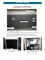
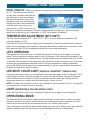
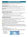
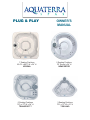
PLUG & PLAY
OWNER’S
MANUAL
7 Seating Positions
80.5”L x 80.5” W x 34” H
VERONA
5 Seating Positions
78" Round x 34” H
NEWPORTER
5 Seating Positions
75”L x 75” W x 34” H
TRANSPORT™
3 Seating Positions
72”L x 72” W x 31” H
TOSCANO
AquaTerra OWNER'S MANUAL
115/230V System
Owner's Record
Locating the Spa Serial Number:
The spa serial number label is located on control box cover inside the equipment compartment.
Equipment compartment access panel is below the spas 4-button topside control panel. You will
need the spa model and serial number to properly register your spa and activate coverage. Write
your spa information in the space provided.
DATE PURCHASED:
PURCHASED FROM:
SPA MODEL:
SERIAL NUMBER:
Please read this “Owner’s Manual” carefully, as it is designed to provide you with the information
you will need to ensure the safe, secure use of your spa.
IMPORTANT: Watkins Manufacturing Corporation reserves the right to change specifications
and/or design without notification and without any obligation.
SPA DIMENSIONS
Model
Spa Seating
Length
Width
Height
Verona
7 person
80.5"
80.5"
34"
Newporter
5 person
78"
78"
34"
Transport
5 person
75"
75"
34"
Toscano
3 person
72"
72"
31"
Dry Weight
475 lbs.
413 lbs.
449 lbs.
403 lbs.
CAUTION
DO NOT OPERATE SPA BEFORE READING THIS MANUAL
Failure to read this manual and follow its instructions may result in unsafe operation and or
permanent damage to your portable spa.
Most cities, counties, states, and countries require permits for exterior construction and electrical
circuits. In addition, some communities have codes requiring residential barriers such as fencing
and/or self-closing gates on the property to prevent unsupervised access to a pool or spa by
children. Be sure to check with your local agencies for specific requirements.
If you need additional information and/or assistance, please contact Customer Service
at 888-961-7727 or at [email protected].
Thank you for choosing an AquaTerra Spa. Visit our web site at www.AquaTerraspas.com.
TABLE OF CONTENTS
TITLEPAGE
SAFETY INFORMATION
IMPORTANT SAFETY INSTRUCTIONS.....................................................................................................................................1
IMPORTANT SPA INSTRUCTIONS.............................................................................................................................................4
INSTALLATION
PLANNING A LOCATION FOR YOUR SPA................................................................................................................................5
PLACING THE SPA.......................................................................................................................................................................6
EQUIPMENT ACCESS
EQUIPMENT ACCESS PANEL....................................................................................................................................................7
ELECTRICAL REQUIREMENTS
ELECTRICAL REQUIREMENT....................................................................................................................................................8
CONFIGURING SYSTEM ............................................................................................................................................................9
ELECTRICAL WIRING DIAGRAM FOR 220V USE.................................................................................................................10
CONTROL PANEL OPERATION
TEMPERATURE ADJUSTMENT (80°F-104°F)........................................................................................................................11
JETS OPERATION......................................................................................................................................................................11
LED MULTI COLOR LIGHT (VERONA & TRANSPORT™ MODELS ONLY)........................................................................ 11
LIGHT (NEWPORTER & TOSCANO MODELS ONLY)...........................................................................................................11
OPERATIONAL MODE: .............................................................................................................................................................11
PRESET FILTER CYCLES ........................................................................................................................................................12
FREEZE PROTECTION ............................................................................................................................................................12
DIAGNOSTIC LCD MESSAGE.................................................................................................................................................13
COMPONENT OPERATION
SPA COMPONENT OPERATION..............................................................................................................................................14
FILL UP AND START-UP INSTRUCTIONS
FILLING THE SPA WITH WATER..............................................................................................................................................15
APPLYING POWER....................................................................................................................................................................15
ADDING START-UP CHEMICALS
WATER CHEMISTRY GUIDELINES..........................................................................................................................................16
SPA MAINTENANCE
FILTER CARTRIDGE MAINTENANCE.....................................................................................................................................17
SURFACE CARE.........................................................................................................................................................................18
COVER CARE.............................................................................................................................................................................18
CABINET CARE ..........................................................................................................................................................................18
SPA LED/BULB REPLACEMENT..............................................................................................................................................18
DRAINING OR WINTERIZING
DRAINING YOUR SPA ...............................................................................................................................................................19
WINTERIZING YOUR SPA.........................................................................................................................................................19
TROUBLESHOOTING PROCEDURES
NO COMPONENT OPERATION................................................................................................................................................20
PUMP DOES NOT OPERATE, BUT THE LIGHT DOES.........................................................................................................20
POOR JET ACTION....................................................................................................................................................................20
WATER IS TOO HOT...................................................................................................................................................................20
REPLACEMENT PARTS
REPLACEMENT SPA PARTS....................................................................................................................................................21
LIMITED WARRANTY- AquaTerra
WARRANTY ................................................................................................................................................................................22
SAFETY INFORMATION
IMPORTANT SAFETY INSTRUCTIONS
READ AND FOLLOW ALL INSTRUCTIONS
AVOIDING THE RISK TO CHILDREN
DANGER:
• RISK OF CHILD DROWNING. Extreme caution must be exercised to prevent unauthorized access
by children. To avoid accidents, ensure that children cannot use a spa unless they are supervised at
all times.
WARNING:
• To reduce the risk of injury, do not permit children to use this product unless they are closely
supervised at all times.
• To reduce the risk of injury, lower water temperatures are recommended for young children. Children
are especially sensitive to hot water.
DO:
• Make sure you always lock the child resistant locks after using the spa for your children’s safety.
Every spa is equipped with a locking cover that meets the ASTM F1346-91 Standard for Safety
Covers.
• Test the water temperature with your hand before allowing your child to enter the spa to be sure that
it’s comfortable. Children are especially sensitive to hot water.
• Remind children that wet surfaces can be very slippery. Make sure that the children are careful when
entering or exiting the spa.
DON’T:
• Allow children to climb onto the spa cover.
• Allow children to have unsupervised access to the spa.
AVOIDING THE RISK OF ELECTROCUTION
Risk of electrocution
• Connect only to a grounded source.
• Do not bury the power cord. A buried power cord may result in death or serious personal injury due
to electrocution if direct burial-type cable is not used, or if improper digging occurs.
• A ground terminal (pressure wire connector) is provided on the control box inside the unit to permit
connection of a minimum No. 10 AWG solid copper bonding conductor between this point and any
metal equipment, metal water pipe, metal enclosures of electrical equipment, or conduit within five
feet (1.5 m) of the unit as needed to comply with local requirements.
WARNING:
• To reduce the risk of electrical shock, replace a damaged cord immediately. Failure to do so may
result in death or serious personal injury due to electrocution.
• Your spa is provided with a Ground Fault Circuit Interrupter for user and equipment protection. To
ensure proper operation of this important safety device, test according to the following instructions
per electrical configuration.
1
SAFETY INFORMATION
115 VOLT, CORD-CONNECTED MODELS:
• The GFCI is located at the end of the power cord. Before each use, with the unit operating,
push the TEST button. The unit should stop operating and the GFCI power indicator will
go out. Wait 30 seconds and then reset the GFCI by pushing the RESET button. The GFCI
power indicator will turn on, restoring power to the spa. If the interrupter does not perform in
this manner, there may be an electrical malfunction and with it, the possibility of an electric
shock. Disconnect the power until the problem has been corrected.
NOTE: This will reset the filter cycle.
230 VOLT, CONVERTED MODELS:
• A ground terminal is provided on the control box. To reduce the risk of electric shock, connect this
terminal to the grounding terminal of your electrical service or subpanel with a continuous green,
insulated copper wire. The wire must be equivalent in size to the circuit conductors supplying the
equipment. In addition, a bonding terminal (pressure wire connector) is provided on the outside of
the control box for bonding to local ground points. To reduce the risk of electric shock, this connector
should be bonded with a No. 8 AWG (8.4 mm²) solid copper wire to any metal ladders, water pipes,
or other metal within 5 feet (1.5 m) of the spa to comply with local requirements. The means of
disconnection must be readily accessible, but must be installed at least 5 feet (1.5 m) from the spa.
• Your spa requires a suitably rated circuit breaker to open all ungrounded supply conductors.
• Your spa must have a ground fault circuit interrupter in an electrical subpanel. Before each use of
the spa and with the unit operating, push the TEST button on the breaker. The switch should click
over to the “Trip” position. Wait 30 seconds and reset the GFCI breaker by switching it completely
off and then completely on. The switch should then stay on. If the interrupter does not perform in
this manner, it is an indication of an electrical malfunction and the possibility of an electric shock.
Disconnect the power until the fault has been identified and corrected.
IMPORTANT: Failure to wait 30 seconds before resetting the GFCI may cause the spa’s Power
Indicator (on the control panel) to blink. If this occurs, repeat the GFCI test procedure.
DANGER: RISK OF ELECTRICAL SHOCK
• Install spa at least 5 feet (1.5 m) from all metal surfaces. A spa may be installed within 5 feet of
a metal surface if each metal surface is permanently connected by a minimum No. 10 AWG solid
copper conductor attached to the wire ground connector on the terminal box that is provided for this
purpose if in accordance with National Electrical Code ANSI/NMFPA70-1993.
• Do not permit any electrical appliances, such as a light, telephone, radio, or television within 5 feet
(1.5 m) of a spa. Failure to maintain a safe distance may result in death or serious personal injury
due to electrocution if the appliance should fall into the spa.
• Install your spa in such a way that drainage is away from the electrical compartment and from all
electrical components.
DO:
• Be sure your spa is connected to the power supply correctly - use a licensed electrical contractor.
• Disconnect the spa from the power supply before draining the spa or servicing the electrical
components.
• Test the Ground Fault Circuit Interrupter(s) before each use.
2
SAFETY INFORMATION
DON’T:
• Use the spa with the equipment compartment door removed.
• Place electrical appliances within 5 feet (1.5m) of the spa.
• Use an extension cord to connect the spa to its power source. The cord may not be properly
grounded and the connection is a shock hazard. An extension cord may cause a voltage drop, which
will cause overheating of the jet pump motor and motor damage.
• Attempt to open the electrical control box. There are no user serviceable parts inside.
RISKS TO AVOID
DANGER: RISK OF INJURY
• DO NOT sit in the filter compartment area. Sitting in this area can cause:
a) Restriction of Filter Pump suction/vacuum
b) Damage to components
• Both can result in bodily harm. Should damage occur to components in this area, replace
immediately!
To reduce the risk of injury to persons, DO NOT remove floating weir, basket, and filter located in
the filter compartment while the spa is running.
• The suction fittings in the spa are sized to match the specific water flow created by the pump. Never
replace a suction fitting with one rated less than the flow rate marked on the original suction fitting.
• There is a danger of slipping and falling. Remember that wet surfaces can be very slippery. Take
care when entering or exiting the spa.
• Never operate spa if the suction fittings are broken or missing.
• People with infectious diseases should not use the spa.
• Keep any loose articles of clothing or hanging jewelry away from rotating jets or other moving
components.
Increased side effects of medication
• The use of drugs, alcohol or medication before or during spa use may lead to unconsciousness with
the possibility of drowning.
• Persons using medications should consult a physician before using a spa; some medication may cause
a user to become drowsy, while other medication may affect heart rate, blood pressure, and circulation.
• Persons taking medications which induce drowsiness, such as tranquilizers, antihistamines or
anticoagulants should not use the spa.
Health problems affected by spa use
• Pregnant women should consult a physician before using spa.
• Persons suffering from obesity or with a medical history of heart disease, low or high blood pressure,
circulatory system problems, or diabetes should consult a physician before using spa.
Unclean water
• Keep the water clean and sanitized with correct chemical care. The recommended levels for your
your spa are: Free Available Chlorine (FAC): 3.0-5.0 ppm Total Alkalinity:
80 - 120 ppm
Water pH:
7.2 - 7.8
Calcium Hardness: 100- 250 ppm
IMPORTANT: Turn jet pump on for at least ten minutes after adding ANY spa water chemicals into the filter compartment.
• Clean the filter cartridge monthly to remove debris and mineral buildup which may affect the
performance of the hydromassage jets, limit the flow, or trip the high-limit thermostat which will turn
off the entire spa.
3
SAFETY INFORMATION
AVOIDING THE RISK OF HYPERTHERMIA
Prolonged immersion in hot water can result in HYPERTHERMIA, a dangerous condition which
occurs when the internal temperature of the body reaches a level above normal (98.6°F, 37ºC).
The symptoms of hyperthermia include unawareness of impending hazard, failure to perceive
heat, failure to recognize the need to exit the spa, physical inability to exit the spa, fetal damage in
pregnant women, and unconsciousness resulting in a danger of drowning.
WARNING:
The use of alcohol, drugs, or medication can greatly increase the risk of fatal hyperthermia in hot
tubs and spas.
TO REDUCE THE RISK OF INJURY:
• The water in the spa should never exceed 104°F (40°C). Water temperatures between 100°F
(38°C) and 104°F (40°C) are considered safe for a healthy adult. Lower water temperatures are
recommended for extended use (exceeding 10 minutes) and for young children. Extended use can
cause hyperthermia.
• Pregnant or possibly pregnant women should limit spa water temperatures to 100°F (38°C). Failure
to do so may result in permanent injury to your baby.
• Do not use spa immediately following strenuous exercise.
AVOIDING THE RISK OF SKIN BURNS:
• To reduce the risk of injury, before entering a spa the user should measure the water temperature
with an accurate thermometer.
• Test the water with your hand before entering the spa to be sure it’s comfortable.
SAFETY SIGN
A SAFETY SIGN in the owner’s package. The sign, which is required as a condition of Product
Listing, should be permanently installed where it is visible to the users of the spa.
IMPORTANT SPA INSTRUCTIONS
The following contains important spa information, and we strongly encourage you to read and
apply them.
DO:
• Use and lock the vinyl cover when the spa is not in use, whether it is empty or full.
• Follow the Spa Care and Maintenance recommendations stated in this manual.
• Use only approved accessories and recommended spa chemicals and cleaners.
DON’T:
• Leave the spa exposed to the sun without water or the vinyl cover in place. Exposure to direct
sunlight can cause solar distress of the shell material.
• Roll or slide the spa on its side. This will damage the siding.
• Lift or drag the cover by using the cover lock straps; always lift or carry the cover by using the handles.
• Attempt to open the electrical control box. There are no user serviceable parts inside. Opening of the
control box by the spa owner will void the warranty. If you have an operational problem, carefully go
through the steps outlined in the Troubleshooting section. If you are not able to resolve the problem,
contact your authorized dealer. Many problems can easily be diagnosed over the telephone by an
Authorized Service Technician
4
INSTALLATION
PLANNING A LOCATION FOR YOUR SPA
Consider these things when determining where to place your spa.
SAFETY FIRST:
Make sure your spa is positioned so access to the equipment compartment and side panels
will not be blocked. Be certain your installation will meet all city and local safety codes and
requirements.
PLANNED USE OF SPA:
How you intend to use your spa will help you determine where you should position the spa. For
example, will you use it more for recreational or therapeutic purposes? If your spa is mainly for
family recreation, leave plenty of room around it for activity and lawn furniture. If you will use it
more for relaxation and therapy, you’ll probably want to create privacy mood around the spa.
PRIVACY:
Think of your surroundings during all seasons to determine your best privacy options. Consider
the view of your neighbors when you plan the location of your spa.
VIEWS:
Think about the direction you will be facing when sitting in your spa. Do you have a special
landscape you will find enjoyable? Perhaps there is an area that has a soothing breeze during the
day or a lovely sunset in the evening.
ENVIRONMENT:
If you live in a climate with a snowy winter and hot summer, a place to change clothes or a house
entry near the spa is convenient. A warmer climate may require shade from the hot sun. Consider
placement of trees, shrubs, patio cover or perhaps a gazebo structure to provide what you will
need. Indoor installations require adequate ventilation. When the spa is in use, considerable
amounts of moisture are produced. This moisture can damage walls and ceiling surfaces over
time. Special paint is available to resist moisture damage. Remember that spas periodically
require drainage, so plan your environment accordingly.
KEEP CLEAN:
Prevent dirt and foliage from being tracked into your spa by utilizing concrete for paths and access
areas. Check the location of spill paths from gutters, trees, and shrubs.
SERVICE ACCESS:
Many people choose to install tile or custom wood around their spas. If you are installing your tub
with custom decorative trimming, remember to allow for access to it for service. Should you need
service, a technician may need to remove the tub’s door panel, or access it from beneath. It is
always best to design special installations so the spa can still be moved, or lifted from the ground.
A GOOD FOUNDATION
Your new spa needs a good solid foundation. The area your spa sits on must be able to support
the spa, the water in it and those who use it. If the foundation is inadequate, it may shift or settle
after the spa is in place, causing stress to the shell or components.
5
INSTALLATION
BE AWARE:
Damage caused by inadequate or improper foundation support is not covered by the spa warranty.
It is the sole responsibility of the spa owner to provide a proper foundation for the spa.
Make sure the foundation where the spa is placed drains water away from the spa. Proper
drainage will keep components dry from rain and wet weather.
Your spa weight must always be considered when installing your spa. If you are installing it on an
elevated wood deck or other structure, it is advisable to consult a structural engineer or contractor
to ensure the structure will support the weight.
IT IS STRONGLY RECOMMENDED THAT A QUALIFIED, LICENSED CONTRACTOR
PREPARE THE FOUNDATION FOR YOUR SPA.
A reinforced concrete pad at least four inches thick is recommended for your spa. The reinforcing
rod or mesh in the pad should be attached to a bond wire.
INDOOR INSTALLATION:
Be aware of some special requirements if you place your spa indoors. Water will accumulate
around the spa, so flooring materials must provide a good grip when wet. Proper drainage is
essential to prevent a build-up of water around the spa. When building a new room for the spa, it
is recommended that a floor drain be installed. The humidity will naturally increase with the spa
installed. Water may get into woodwork and produce dryrot, mildew, or other problems. Check for
airborne moisture’s effects on exposed wood, paper, etc. in the room. To minimize these effects, it
is best to provide plenty of ventilation to the spa area. An architect can help to determine if more
ventilation must be installed.
PLACING THE SPA
CHECK THE DIMENSIONS OF YOUR SPA:
Compare the spa dimensions to the width of gates, sidewalks, and doorways along the delivery
route used to bring the spa into your yard. It may be necessary for you to remove a gate or
partially remove a fence in order to provide an unobstructed passageway to the installation
location. Also, keep in mind—if you are using special equipment to place your spa into an area it
will be necessary to include those measurements and weights.
PLANNING A DELIVERY ROUTE:
Check the width of gates, doors and sidewalks to make sure your spa will pass through
unobstructed. You may have to remove a gate or part of a fence to allow for adequate width
clearance. If the delivery route will require a 90-degree turn, check the measurements at the turn
to ensure the spa will fit. Check for protruding gas meters, water meters, A/C units, etc., on your
home which will cause obstructions along the delivery path to your yard. Check for low roof eaves,
over hanging branches or rain gutters that could be an obstruction to overhead clearances.
SPECIAL CIRCUMSTANCES:
The use of a crane for delivery and installation is primarily to avoid injury to your spa, your
property or to delivery personnel. Our customer service may be able to assist you with the
arrangements. Cranes are not considered “normal delivery”.
6
EQUIPMENT ACCESS
EQUIPMENT ACCESS PANEL
Topside Control Panel
Slat
Slat
Equipment Access Panel Door
Screw
Drain Hose
Electrical Recess
To access the equipment compartment:
• Remove 1 vertical slat and 3 screws on each side of Equipment Access Panel Door.
• Remove 6 screws from Equipment Access Panel Door then remove door.
• Remove screws from black ABS Door (if your spa has vertical slats) to access
Equipment Compartment.
Electrical
Access
Black ABS Door
Hose
Bib
Equipment Compartment
7
ELECTRICAL REQUIREMENTS
ELECTRICAL REQUIREMENT
DO NOT POWER THE SPA WITHOUT FIRST FILLING WITH WATER!
DANGER – RISK OF ELECTRIC SHOCK
Installations that do not conform to the following procedures and requirements may expose
users to electric shock. Non-conforming installations will not be covered under warranty.
If installed in the United States, the electrical wiring of this spa must meet the requirements of the
National Electric Code (NEC) and any applicable state or local codes. The electrical circuit must be
installed by an electrical contractor and approved by a local building electrical inspection authority.
1. Installations within 5 feet of any metal surfaces must ground the metal surfaces to the hot tub.
Use an 8 AWG solid copper wire and attach it to the grounding lug on the power pack, located
in the equipment compartment.
2. Only a licensed electrician may install power to the spa.
3. Power supply installation must include a suitably rated ground fault interrupter (GFCI) as
required by NEC Article 680-42. The circuit breaker must be dedicated and should not be
shared with any other appliances. It must be labeled and easily accessible to users.
4. The electrical supply for the spa must include a suitable rated switch or circuit breaker to open
all ungrounded supply conductors to comply with Section 422-20 of the National Electric Code,
ANSI/NFPA 70. The disconnecting means must be readily accessible to the spa’s occupant but
installed at least 5 feet from the spa water.
5. Power supply lines must be hard wired into the power pack. DO NOT use extension or plugtype cords of any kind. The use of a shut-off box near the hot tub is also recommended. This
box provides a quick and convenient method to shut off power to the hot tub for emergencies
and maintenance.
6. Supply lines must be properly sized as per the NEC (National Electric Code). A ground line
must be provided that is as large as the largest current carrying conductor, but no less than 8
AWG. Use copper wiring only.
7. Please open the front cover of the control box, and follow the instructions and wiring diagram
printed on the backside.
8. All 115V powered models must use the provided 15 foor GFCI cord and be pluged directly
into a dedicated grounded wall outled.
9. CAUTION, 230V POWERED SPAS – These
spas must be hard wired to your household
electrical service box only. Do not use an
extension cord or any other disconnect-able
power cord. The use of an extension cord
or a disconnect-able power cord is highly
dangerous and will void all warranties!
• Wire size must be appropriate per NEC and/or
local codes.
• Wire size is determined by length of run from
Equipment access is below
breaker box to spa and maximum current draw.
the topside control panel.
• THHN copper core wire is recommended.
• All wiring must be copper to ensure adequate connections. Do not use aluminum wire.
8
ELECTRICAL REQUIREMENTS
CONFIGURING SYSTEM
SELECTING THE VOLTAGE FOR YOUR SPA
Your spa is designed to operate at either 115V 15 amp, or 230V which requires a dedicated 230
volt 40 amp power supply. When the spa is setup for 115V, the heater will provide approximately
1000 watts of heat only when the pump is operating in LOW speed and the thermostat is calling
for heat (NOTE: The heater does not operate when the pump is on high speed). When the spa is
connected to 230 volts, the heater will provide approximately 4000 watts of heat when the pump is
operating in LOW or HIGH speed and the thermostat is calling for heat.
All electrical connections must be made in accordance with the wiring information contained on
the electrical control box cover.
115 VOLT INSTALLATION
Spas come with a factory-installed power supply GFCI cord and are to be plugged into a grounded
type 115 volt, 15 ampere receptacle. No other electrical appliance or fixture can be used on this
circuit.
IMPORTANT: Under NO circumstances should an extension cord be used. Use of an extension
cord will seriously degrade the performance of the equipment module and can create an electrical
hazard.
115V Input Voltage
230V Input Voltage
Jumper Wire J11 - J32
Dip Switches 2,7 & 10 UP
OFF/DOWN
ON/UP
1 2 3 4 5 6 7 8 9 10
Dip Switches 2 & 7 UP
1 2 3 4 5 6 7 8 9 10
230 VOLT INSTALLATION
When converting the spa to 230V, Dip Switch 10 must be set to the down position. A jumper wire
from J11 to J32 must also be removed. See following page for 220V Installation instructions.
MODE OPTION (DIP SWITCH 7 SETTING)
The spa has been pre-programmed to operate in the Standard Operational Mode ONLY (page12).
The spa may be configured to have three operational modes. To change your spa to allow 3
different modes, we recommend you contact customer service and schedule service. Dip Switch
#7 on the power supply board must be moved down into the “off” position allowing you to select
either Standard, Economy, or Sleep modes using the topside control panel.
9
ELECTRICAL REQUIREMENTS
ELECTRICAL WIRING DIAGRAM FOR 230V USE
It is recommended that a licensed electrician install the power to your spa in accordance with the
National Electric Code and/or any local electrical codes in effect at the time of installation.
Power supply installation must include a properly rated GFCI circuit breaker. The circuit must be
dedicated and should not be shared with any other appliances. The power supply must be hard
wired into the power pack.
230V Wiring Instructions:
4 wires/Minimum 40 amp GFCI
Breaker #8 AWG 75°C Copper Wire
Minimum (less than 100’ length)
Special Note:
If the GFCI Breaker trips immediately
after attempting to turn on, please
check the White Neutral Wire that is
connected to the Spa.
White Neutral Wire that is connected
to Spa Neutral goes HERE.
From the House
Breaker Box
To the Spa
10
CONTROL PANEL OPERATION
INITIAL START-UP - When your spa is first powered up it will go into priming mode, indicated
by “Pr”. The priming mode will last
for less than 5 minutes and then the
spa will begin to heat and maintain
the water temperature when in the
Standard mode. Your spa has been
designed so that it will automatically
heat the water to the factory set
temperature of 100°F unless you set
the spa to a different temperature. If power is disconnected from the spa, it will automatically
revert back to the factory set Temperature of 100°F when power is reapplied.
TEMPERATURE ADJUSTMENT (80°F-104°F)
Can only function between 80°F - 104°F / 26°C - 40°C. The last measured temperature will
constantly display on LCD.
Press the Up or Down buttons to display the set temperature. Each time either button is pressed
again, the set temperature will increase or decrease depending on which button is pressed. After
three seconds, the LCD will automatically display the current spa temperature.
JETS OPERATION
Firmly press the Jets button once to activate the low speed of the pump and again for the high
speed. Firmly press the Jets button again to turn off the pump. If left running the low speed of the
pump will automatically turn off after 4 hours. The high speed pump will automatically turn off after
15 minutes. The low speed of the pump may also activate for at least 2 minutes every 30 minutes
to detect the spa temperature and then to heat to the set temperature if needed, depending
upon mode. When the low speed turns on automatically it cannot be deactivated from the panel:
However the high speed may be started.
LED MULTI COLOR LIGHT (VERONA & TRANSPORT™ MODELS ONLY)
Press the Light button once to turn on the light. Press the button again to turn the light off. Every
time the light is quickly turned off and back on, a new color will illuminate. There are 6 different
colors followed by a color wheel. The color wheel starts out as a white light. Exiting the color
wheel may require you to press the light button quickly 4 times or more.
NOTE: The blue color is the first of the 6 colors followed by the color wheel. If left on, the light will
automatically turn off after 4 hours of operation.
LIGHT (NEWPORTER & TOSCANO MODELS ONLY)
Press the Light button once to turn on the light. Press the button again to turn the light off.
OPERATIONAL MODE:
The Standard Mode is the default operational mode preset from the factory. In order to program
the spa to operate in the other 2 modes allowing you to change the mode, dip switch #7 on the
control box board must be moved downward into the "off" position (See page 9).
If your spa has been modified to allow mode change, press the Up or Down button, then while the
display is flashing press the light button to go into Standard, Economy or Sleep Mode.
11
CONTROL PANEL OPERATION
STANDARD MODE: Is programmed to maintain the desired temperature.
Note: the last measured spa temperature displayed is current only when the pump has been
running for at least 2 minutes.
“St” will be display momentarily only when dip switch 7 is OFF.
ECONOMY MODE: Heats the spa to the set temperature only during filter cycles.
“Ec” will display solid when temperature is not current and will alternate with temperature when
temperature is current (Ec will only display if dip switch 7 is OFF, see pg. 9).
SLEEP MODE: Heats the spa within 20º F (6.6º C) of the set temperature only during filter
cycles.
“SL” will display solid when temperature is not current and will alternate with temperature when
temperature is current (SL will only display if dip switch 7 is OFF, see pg. 9).
PRESET FILTER CYCLES
The first filter cycle begins 6 minutes after the spa is powered up. The second filter cycle begins
12 hours later. Filter duration is programmable for 1, 2, 3, 4, 5, 6, 7, 8 or 12 (FC) hours.
• The default filter time is 1 hour.
• To program, press Down or Up then press Jets. Press Down or Up to adjust
• Press Jets to exit programming. Pump low speed will run for the duration.
The low speed of the pump runs during filtration and the ozone generator will be enabled.
FREEZE PROTECTION
If the temperature sensors detect within the heater, a drop to below 44°F (7º C), the pump will
automatically activate to provide freeze protection. The equipment stays on until 4 minutes after
the sensors detect that the spa temperature has risen to 44°F (7º C) or higher.
Warning! Shock Hazard! No User Serviceable Parts.
Do not attempt service of this control box. Contact Customer Service for assistance. Follow
all owner manual power connection instructions. Installation must be performed by a licensed
electrician and all grounding connections must be properly installed.
WARNING! DO NOT ENTER SPA IF WATER IS TOO HOT
Water is too hot. Overheat protection heater is deactivated. Spa water temperature is above
acceptable limits. When the actual water Temperature is approximately 2º F (1º C) above the set
temperature, the circulation pump will stop operating to reduce (frictional) heating. If the spa water
temperature continues to rise and gets above 110º F (44ºC), the spa will go into an “OH” overheat
condition.
To correct Condition:
1. Remove the spa’s cover and allow your spa to cool down.
2. Reduce the temperature setting.
3. When the water temperature drops below 106º F (41ºC), the spa will resume normal operation.
4. If the water does not drop below 106ºF (41ºC), contact your authorized customer service.
Note: Your spas topside control panel has been designed to include:
a) Jets button
b) Light button
c) Down heat button
d) Up heat button
LED Heat Indicator
12
CONTROL PANEL OPERATION
DIAGNOSTIC LCD MESSAGE
Message Meaning
No message on display.
Power has been cut off to the spa.
-HH
OH
IC
SA
Sb
Sn
HL
LF
Dr
dY
Action Required
The control panel will be disabled until power
returns. Spa settings will be preserved until next
power up.
Temperature unknown
After the pump has been running for 2 minutes,
the temperature will be displayed.
“Overheat” – The spa has shut
DO NOT ENTER THE WATER. Remove the
down. One of the sensors has despa cover and allow water to cool. Once the
tected 118ºF at the heater.
heater has cooled reset by pushing any button.
If spa does not reset, shut off the power to the
spa and call Customer Service.
“Overheat” – the spa has shut down. DO NOT ENTER THE SPA. Follow same
One of the sensors has detected
instructions as above.
that the spa water is 110ºF.
“Ice” – Potential Freeze condition
No action required. The pump will automatically
detected.
activate regardless of spa status.
Spa is shut down – The sensor that If the problem persists, contact Customer
is plugged into the Sensor “A” jack is Service. It may appear temporarily in an
not working.
overheat situation and disappear at cool.
Spa is shut down. The sensor that
If the problem persists, contact Customer
is plugged into the Sensor “B” jack is Service. It may appear temporarily in an
not working.
overheat situation and disappear at cool.
Sensors are out of balance. If alIf problem persists, contact Customer Service.
ternating with spa temperature, it
may just be a temporary condition. If
flashing by itself, spa is shut down.
A significant difference between
Check water level in spa. Refill if necessary. If
temperature sensors has been
the water level is okay, make sure the pumps
detected. This could indicate a flow have been primed. If problem persists, contact
problem.
Customer Service.
Persistent low flow problem (DisFollow action required for “HL” message.
plays on the fifth occurrence of “HL” Heating capability of the spa will not reset
message within 24 hours.) Heater is automatically; you may press any button to
shut down, but other spa functions
reset.
continue to run normally.
Possible inadequate water, poor
Check water level in spa. Refill if necessary. If
flow, or air bubbles in detected in
water level is okay, make sure the pumps have
the heater. Spa is shut down for 15 been primed. Press any button to reset, or
minutes.
this message will automatically reset within 15
minutes. If problem persists, contact Customer
Service.
Inadequate water detected in heater Follow actions required for “Dr” message. Spa
(Displays on third occurrence of “Dr” will not automatically reset. Press any button to
message.) Spa is shut down.
reset.
13
COMPONENT OPERATION
SPA COMPONENT OPERATION
AIR CONTROL VALVE
The air control valve serves to regulate the amount of air mixed with the water when the jets
are operational. Rotate all the air control valves counterclockwise and observe the increased jet
action. Rotating the air control in the opposite direction to turn air off and allow the jets to work
with water only. Turn the air controls off when the spa is not in use, this will prevent cold air from
entering the spa and will keep heating cost to a minimum. The ozone generator infusion jet, will
always produce air bubbles when pump is on.
DIVERTER VALVE (TRANSPORT™ MODEL ONLY)
The diverter valve on your spa allows you to direct the flow of water from the pump to one of two
combinations of jets. The function of the diverter valve can best be learned by experimentation.
Turn the large valve all the way to one side or the other to see which jets are on.
WHIRLPOOL JET (NEWPORTER MODEL ONLY)
The Whirlpool Jet is located below the water line at or near the control panel area, in the wall.
This jet is a diverter valve and high capacity jet that has a larger diameter than the hydrotherapy
jets. The whirlpool jet is turned on and off by rotating the jet face. Because, there is a substantial
amount of water pressure when the jet is in operation, you must turn the pump off or to low speed
before attempting to rotate the jet face. As the whirlpool jet open position is increased it will begin
turning off all of the hydrotherapy jets. One of the two air control valves is dedicated to the this jet.
HYDROTHERAPY JETS
The hydrotherapy jets are recessed in the wall of the spa. Rotate the medium jet faces counterclockwise to turn the jets on, clockwise to turn the jets off. Turning a jet on or off will increase or
decrease the effects of any jets “not” in the closed position.
LED MULTI-COLOR LIGHT (VERONA & TRANSPORT™ MODELS ONLY)
Your spa is installed with a LED multi-color light, pressing the light switch button on and off will
cause the light color to change to your desired color. If your spa is equipped with a standard 12V
light bulb you can purchase a multi-color light at www.AquaTerraspas.com.
OZONE GENERATOR (VERONA & TRANSPORT™ MODELS ONLY)
The ozone system greatly enhances the quality of the spa water when used to supplement
the spa owner’s regular water maintenance program. Contrary to some information circulated
throughout the pool and spa industry regarding ozone systems, ozone CAN NOT be used as
a single-source sanitizer, water clarifier, anti-foamer, and mineral chelating agent. A secondary
source sanitizer must be used to maintain 2.0 ppm (2.0 mg/L) of Free Available Chlorine (FAC).
Watkins Manufacturing Corporation recommends that a chemical maintenance program based on
recognized and documented industry standards still be followed when using an ozone purification
system to assure water sanitation and the highest quality purified water.
WATERFALL
Your spa has a control valve to operate the amount of flow through the waterfall from no flow to a
steady stream. This valve is located next to the waterfall.
Note: The air control valve and the waterfall flow valve may look and function exactly the same
and may operate in the same way, however; they will be separate components.
14
FILL UP AND START-UP INSTRUCTIONS
The following procedures should be followed on initial startup and whenever the spa is drained for
routine maintenance.
FILLING THE SPA WITH WATER
1. Clear all the debris from your spa.
2. Be sure to open all Jets to allow as much air as possible to escape from the plumbing during
the filling process.
3. Use a garden hose to fill your spa with water.
NOTE: Do not use hot or softened water.
4. As the water level rises, check inside the
equipment compartment for water leaks. It
may be necessary to tighten unions and/
or fittings that may have loosened during
delivery. There is no need to call for service;
this can easily be done by you. If assistance
is required, contact a customer service
representative at (888) 961-7727
5. Under normal circumstances keep the water
level half way between the top of the spa and
the top of the grey filter ring or just above the
highest jets (whichever is higher).
Failure to keep enough water in your spa may
result in damage to your system & invalidate
your warranty. If your spa filter is sucking in
air causing the pump to cavitate, you need to add water!
UNIONS
6. Check the filter installation and make sure the filter is not loose.
APPLYING POWER
1. Plug the spa into the 15 amp dedicated, grounded wall outlet for 110V. Turn power to spa
"ON" from the Main Panel and the subpanel for 220V.
2. Press the Jets button on the topside control panel to activate the spa. Rotate all the air control
valves counterclockwise and observe the increased jet action (air mixed with water).
3. While the pump is running check again for water leaks at the drain spigot, unions, or fittings in
the equipment compartment (leaks may have occurred during transit). If water is leaking from
one of these areas, there is no need to call for service. Simply tighten the fitting. If assistance
is required, call a Customer Service representative at (888) 961-7727.
4. After checking your spa for leaks it is now time to adjust your spa settings. Press the “Up”
or "Down" button on your topside control panel until the display indicates your desired
temperature is set.
15
ADDING START-UP CHEMICALS
WATER CHEMISTRY GUIDELINES
The following step-by-step instructions are a recommended guideline for balancing water chemistry. If
unsure about any step in the process, please contact a Customer Care Associate at (888) 961-7727) or
by email at [email protected].
Initially, it is advisable to identify what minerals (e.g. iron) are present in the local source water. This will
provide a better understanding of how to treat the water. Please follow the four steps below and be sure to
achieve the correct levels in each area before moving onto the next step.
STEP #1: ESTABLISH PROPER PH LEVEL:
The recommended range for pH is between 7.2 and 7.8. If the reading is too high, lower the pH by
using a pH Down/Decreaser (sodium bisulfate). If the pH level needs to be increased, do so with a pH
Up/Increaser (sodium hydrogen carbonate). Any pH Up or Down should be added one teaspoon at a
time, waiting one-half hour between application and re-measuring.
STEP #2: MEASURE TOTAL ALKALINITY:
The ideal range is between 80-120 parts per million (PPM). If the total alkalinity is too high, it should
be reduced by using an Alkalinity Down/Decreaser (sodium bisulfate). If the total alkalinity is too low,
it can be increased by adding an Alkalinity UP/Increaser (sodium bicarbonate or sodium hydrogen
carbonate). These products should be added in small amounts – a teaspoon at a time. After adding
one teaspoon, wait one half hour before re-measuring. Once the safe range of total alkalinity is
established, proceed to the next step.
STEP #3: DETERMINE CALCIUM HARDNESS:
It is important to bring the calcium reading to between 100-250 PPM. If the reading requires adjustment,
it should now be corrected. If the water is too soft (a low reading) calcium hardness should be added to
the water to increase the PPM reading. If the water is too hard (a high reading), it can be corrected by
either: (A) a mixture of hard and soft water added to attain a reading in the safe range, or (B) addition of
stain and scale control. If calcium hardness is a problem with the local source water (either too hard or
too soft) a test kit, which measures calcium hardness, is essential.
STEP #4: SANITIZING:
After steps 1-3 are complete, the spa must be sanitized using Chlorine (sodium dichlor). Add 2
teaspoons of Chlorine, and increase as necessary to reach a level of 3-5 ppm. Check and maintain
this level weekly, and before and after using the spa. IMPORTANT NOTE: A granulated sodium dichlor
is highly recommended for sanitizing spa water. Never use a sodium trichlor tablet in any form
even with a floater. As with any other chemicals, the sanitizer should be introduced to the spa with
the jets running a minimum of 10 minutes.
WEEKLY SHOCK:
Using a potassium monopersulfate (MPS) shock, add approximately 2 oz. spreading it over the water
while the jets are running. Shocking is achieved by adding the MPS to turbulent water. Leave the cover
up until the jets automatically turn off. The spas are equipped with an automatic time out feature that
will shut the jets off after 15 minutes. Then return the cover to the closed position to maintain heat.
IMPORTANT: Damage caused by dirty, clogged, or calcified filters; damage to the spa surface
caused by improper use of chemicals to lie on the surface; damage caused by improper pH
balance, improper calcium hardness level or other improper water chemistry is not covered under
the spa warranty.
16
SPA MAINTENANCE
FILTER CARTRIDGE MAINTENANCE
Every two weeks, the filter cartridge should be cleaned to remove the objects and particles that
have lodged in the cartridge pleats. Using household water pressure and a garden hose with a
pressurized nozzle, push water from inside to outside of the pleats, forcing all the trapped particles
out.
NOTE: Never run your spa without a filter cartridge!!! This will invalidate your warranty.
NOTE: Filter cartridges should be replaced every six to eight months or earlier when needed.
Dirty filters can cause your spa pump to burn out and will invalidate your warranty.
FILTER CARTRIDGE REMOVAL AND CLEANING INSTRUCTIONS
Spa uses a screw in filter cartridge that is easily removed.
• Turn off the power to the spa, (by turning OFF the subpanel breaker).
• Push down slightly and turn filter basket counter clockwise to unlock, then pull the basket and
weir out.
• Unscrew the filter cartridge counter clockwise and bring it out of the spa (requires many turns).
• Rinse cartridge using a garden hose. Rotate and separate filter pleats while spraying water to
remove all dirt and debris possible. Let filter dry and look for calcium deposits (scaling) or an oil
film. If you find these, you will need to deep clean your filter cartridge with a “spa filter cleaner”
solution to break down and remove unwanted deposits and oils. (For longer filter life you
should soak filter regularly.)
CAUTION! Always use proper eye protection when using chemicals, or high-pressure water.
Read instructions on cleaning products and follow applicable safety and warning instructions listed
on label.
CAUTION! Never scrub the filter cartridge with a brush, as this will cause the filter to wear out and
come apart. Never let the spa pump run without a filter cartridge in the skimmer compartment.
Running the spa without a filter cartridge may permit debris to enter the spa plumbing and void the
warranty!
• Replace filter cartridge, then reinstall basket and weir, (insert and rotate clockwise to lock into
position). DO NOT OVERTIGHTEN!
• Turn spa’s power back on.
17
SPA MAINTENANCE
SURFACE CARE
Do not use solvents or abrasive cleaners to clean the spa. Typically, a mild detergent and water
will resolve cleaning issues.
COVER CARE
Please keep your cover free from dirt at all times. Use a cover cleaner or a warm mild soapy
water to clean the surface. Do not use any silicone-based products, as it will dry and may
eventually crack the vinyl.
NOTE: Do not stand on the cover at any time. Remove the cover when adding chemicals to your
spa. This will extend the life of your cover. The gasses from burned off chemicals will be trapped
under the cover, if not removed. These gasses may eat away at the protective lining of the foam
inserts. This will not be covered under warranty.
CABINET CARE
Little maintenance is required to keep your spa cabinet looking good
Spa cabinet product should be cleaned as needed to remove dirt and debris.
• NO abrasive or harsh chemicals should be used on the spa's cabinet.
• NO solvents or cleaners containing aromatic solvents should be used on the spas cabinet.
• Hot Soapy water is the best choice for cleaning the spa's cabinet.
AVOID PROLONGED EXPOSURE TO DIRECT SUNLIGHT OR EXCESSIVE TEMPERATURES
(100 ºF or 38 ºC) to avoid your spa cabinet from buckling
SPA LED/BULB REPLACEMENT
•
•
•
•
Turn OFF the power to the spa.
Remove the equipment compartment access door.
Locate the rear of the spa light.
To remove the LED/Bulb, turn outside housing counter clockwise ¼ turn, and pull out and
remove LED/Bulb from socket.
• Replace the LED/Bulb by reversing the above steps.
18
DRAINING OR WINTERIZING
Every three to six months, depending upon the water condition, you need to renew your water.
CAUTION: READ THIS BEFORE DRAINING YOUR SPA
• To prevent damage to the spa’s components, TURN OFF SUBPANEL BREAKER BEFORE
DRAINING. Do not power back up until your spa has been refilled with water.
• There are certain precautions to keep in mind when draining your spa. If it is extremely cold,
and the spa is outdoors, freezing could occur in the plumbing or the equipment.
• Do not leave the spa's shell (inside surface) exposed to direct sunlight.
DRAINING YOUR SPA
• If draining for the first time. Pull the hose bib out a few inches from the spa (located in the recess under the spa, just right and below the equipment access door)
• Unscrew and remove the drain cap.
• Attach hose bib to a garden hose and direct to an appropriate
draining area, keeping the hose below the water line.
• After your spa is empty, clean the shell and filter cartridge. See
“Spa Maintenance”
• After cleaning, remove garden hose, replace drain cap and
push the hose bib back into the recess.
• Follow the “Fill up and Start-up Instructions” on page 15.
WINTERIZING YOUR SPA
If you plan to store your spa for the winter, you must also use a wet-vac to clean out the water
lines to ensure they are free of any water. Water left in the lines might freeze and damage the
lines and jets.
1. It will be necessary to remove all water from the interior plumbing.
2. Remove the floating weir, basket, and filter cartridge. Clean the filter cartridge and store in a
dry place. Attach the vacuum hose to the vacuum side of the shop vac and thoroughly dry the
filter compartment.
3. Using the shop vac, remove the water starting with the jets at the top and moving to the ones
at the bottom of the spa.
NOTE: When removing the water from jet openings, you may notice suction coming from
another jet. With the help of a second person, block off any suction from the other jet using a
large rag or cloth. This will help pull out the water that is trapped deep inside the main line.
4. Thoroughly dry the spa shell with a clean towel.
5. Using a funnel, pour Propylene glycol anti-freeze into the filter suction fittings and jet outlets.
CAUTION: Use only Propylene glycol as your anti-freeze. This is non-toxic. NEVER use
automobile anti-freeze since it is toxic.
6. Remove the pump drain plug located on the front of the pump housings. Allow all water to
drain out. Place the drain plug in a reclosable plastic storage bag and store near the pump.
Replace the drain plugs on start-up.
7. Unscrew the suction/discharge pump and heater unions and allow the water to drain. Leave
union loose. NOTE: Tighten unions before filling spa.
8. Replace the equipment compartment door and secure with screws.
Note: Damage caused by improper winterizing will not be covered under warranty. You may want
to contact a professional for proper winterizing.
19
TROUBLESHOOTING PROCEDURES
In the event the spa is not working the way it should, please first review all the installation and
operating instructions in this manual and check the message on the panel display. If you are still
not satisfied it is working properly, please follow the appropriate troubleshooting instructions.
CAUTION! WARNING! SHOCK HAZARD! No User Serviceable Parts.
Do not attempt service of the control box. Contact Customer Service for assistance. Follow all
owner's manual power connection instructions.
NO COMPONENT OPERATION
Check the following:
1. Is there power to the spa?
2. Is the household circuit breaker tripped?
3. Is the subpanel (230V) or cord GFCI (115V) tripped?
4. If 1, 2 or 3 are yes contact Customer Service for service.
PUMP DOES NOT OPERATE, BUT THE LIGHT DOES
Press the JETS button:
The pump operates but no water flows to jets. Pump may not be properly primed. This can happen
after the spa is drained and refilled. Press the JETS button several times, never leaving the motor
on for more than 5-10 seconds at-a-time with no water coming of of jets.
POOR JET ACTION
1.
2.
3.
4.
5.
6.
Press the Jets button to make certain the pump is on.
Rotate all the air control valves counterclockwise and observe the increased jet action.
Make sure the water level is half way between top of spa and top of the gray filter ring.
Check for dirty filter. Clean, if necessary.
Make sure all jets are in the open position (turn counterclockwise).
Make sure the gate valves are in the open position and locked (UP).
WATER IS TOO HOT
1. Check desired temperature on topside control
2. Check for a diagnostic Message (see Control System manual for details)
OH - Overheat (spa is deactivated) DO NOT ENTER THE WATER.
If the spa has overheated you should remove the cover to promote heat reduction. The spa control
system should reset itself when the water temperature reduces below 107ºF or 43ºC. When the
spa falls below the reset temperature you can push any button on the topside control to reset the
control system. If the spa will not reset, then shut off power to the spa and call Customer Service
at (888) 961-7727.
Under extreme and/or prolonged weather conditions it is possible for the ambient temperature to
exceed 107F/43C, therefore; effecting the water temperature of the spa and causing it to overheat.
These conditions could cause the spa sensors to produce an OH message and prevent the usage
of your spa during these conditions. The location of your spa should be reconsidered to reduce the
outside temperature around the spa. For example, you may need to prevent direct sunlight on any
surface of your spa. Regardless, do not enter your spa if the temperature is above 104F.
Should checking the above steps fail to correct the problem, please contact Customer Service at
(888) 961-7727.
20
REPLACEMENT PARTS
REPLACEMENT SPA PARTS
PART NUMBER
DESCRIPTION
PLE 5CH-45
SPA FILTER – 50sq. ft. Filter
BAL 55340
EQUIPMMENT PACK
BAL 54130
4 BUTTON TOPSIDE CONTROL PANEL
BAL 30637
TEMP SENSOR
WAT 519-2087
ROUND FILTER WEIR
WAT 519-2097
FILTER BASKET SKIMMER
CUS 23432812625
DIRECTIONAL JET (single face jet)
CUS 23432832600
ROTATING JET (double face jet)
J&J LS9-1
LED MULTI-COLOR LIGHT
CUS 25239000000
LIGHT BULB (GE 912)
AQU XL-30AE
OZONATOR (IF EQUIPPED)
CAL COVKEYSET
COVER LOCK/KEY SET
CUS 25718-101
FILTER LID (LARGE 11 1/4")
CUS 25718-001
FILTER LID (SMALL 10 3/4")
21
Limited Warranty- AquaTerra
Manufactured by Watkins Manufacturing Corporation, Vista, CA
Five Year Limited Structure Warranty
Watkins warrants the structure of the spa, which is defined as any rotationally molded, polyethylene internal support structures
connecting the unibody shell, floor and the external coping to itself, for a period of five years from the delivery date of the spa. This
limited structural warranty specifically excludes any portion of the spa that is not rotationally molded as part of the unibody shell such as
synthetic wood skirting, jets, doors, covers, etc.
Five Year Shell/Surface Warranty
Watkins warrants the shell of the spa from manufacturing defects resulting in water loss for a period of five years from the delivery date
of the spa. Any and all additional costs including, shipping, delivery, set-up, installation and/ or disposal charges will be the sole
responsibility of the spa owner.
Two Year Cabinet Warranty
Watkins warrants the synthetic wood cabinet material and assembly to be free from defects in materials and workmanship for two years
from the delivery date of the spa. The cosmetic finish is warranted to be free from defects in materials and workmanship at the time of
initial delivery. Fading and weathering of the surface may naturally occur over time and are not considered defects.
One Year Equipment - One Year Labor Warranty
Watkins warrants the electrical and mechanical components including the pump, heater, LED lighting and control system against
malfunctions in materials or workmanship for a period of one year from the delivery date of the spa. Filter cartridges, light bulbs, spa
cover locks, fuses and GFCI cord are not included in this warranty. Those items are, however, warranted to be free from defects in
materials and workmanship at the time of delivery to the consumer.
One Year Ozone - One Year Labor Warranty
Watkins warrants the ozone (if applicable) against malfunctions in materials or workmanship for one year from the delivery date of the
spa.
One Year Plumbing – One Year Labor Warranty
Watkins warrants the factory installed plumbing components for materials and workmanship against leaks for a period of one year from
the delivery date of the spa. This warranty specifically covers jet fittings, internal plumbing, internal glue joints and hoses.
Extent Of Warranty
This warranty extends only to the original consumer purchaser of the spa when purchased and originally installed within the boundaries
of the United States. This warranty begins on your delivery date of the spa, but in no event later than one year from the date of purchase.
This warranty terminates upon any transfer of ownership, or if the spa is installed or relocated outside the boundaries of the United States
by the original consumer purchaser prior to the expiration of the warranty period.
Warranty Performance
To make a claim under this warranty, contact Watkins Manufacturing Corporation, at 1280 Park Center Drive, Vista, California, 92081,
Attn: Customer Service Department or call (888) 961-7727 or via e-mail, [email protected]. You must give Watkins written
notice of any warranty claim, along with a copy of your original purchase receipt indicating the date of the purchase, within ten (10) days
of the time you discover the claim. Watkins reserves the right to inspect the malfunction or defect on location.
Watkins or its Authorized Service Agent will repair any defects covered by this warranty. Except as described herein, you will not be
charged for parts, labor or the freight costs for parts necessary to repair the spa for defects covered by this warranty.
Limitations
Except as described above, this warranty does not cover defects or damage due to normal wear and tear, improper installation, alteration
without Watkins’ prior written consent, accident, acts of God, misuse, abuse, commercial or industrial use, use of an accessory not
approved by Watkins, failure to follow Watkins’ Owner’s Manual, or repairs made or attempted by anyone other than an authorized
representative of Watkins. Alteration includes, but is not limited to, any component or plumbing change, or electrical conversion. Call
(888) 961-7727 for a list of manufacturer approved accessories.
Disclaimers
TO THE EXTENT PERMITTED BY LAW, WATKINS SHALL NOT BE LIABLE FOR LOSS OF USE OF THE SPA OR
OTHER INCIDENTAL OR CONSEQUENTIAL COSTS, EXPENSES, OR DAMAGES, INCLUDING BUT NOT LIMITED TO
THE REMOVAL OF ANY DECK OR CUSTOM FIXTURE OR ANY COST TO REMOVE OR REINSTALL THE SPA, IF
NEEDED. Some states do not allow the exclusion or limitation of incidental or consequential damages, so the above limitations may not
apply to you. ANY IMPLIED WARRANTIES, INCLUDING THE IMPLIED WARRANTIES OF MERCHANTABILITY AND
FITNESS FOR A PARTICULAR PURPOSE, ARE LIMITED TO THE DURATION OF THE APPLICABLE WARRANTY
STATED ABOVE. Some states do not allow limitations on how long an implied warranty may last, so the above limitations may not
apply to you.
Legal Remedies
This warranty gives you specific legal rights, and you may have other rights which vary from state to state.
©2012 Watkins Manufacturing Corporation, Vista, CA. 92081
PN 62826 REV B 2012
22
NOTES:
NOTES:
PART # 303344 REV. C (6/12)