1
-( £ It Ii
.... ., "i;;
",
,,..,,;:~
~
'; ~ ·"""41"·.........'·'
~
4-
.,\. '"':.Ii'"
..._
b(,,~,
,~,
~~:
..,
~
o
q
~LI)"'"
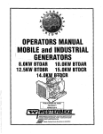
OPERATORS MANUAL
MARINE DIESEL GENERATORS
8.0KW • 60Hz......... 6.0KW • 50Hz BTDA
10.0KW • 60Hz .........7.5KW • 50Hz BTDA
11.5KW • 60Hz ........ ,9.2KW • 50Hz BTD
12.5KW • 60Hz .........9.4KW • 50Hz BTDB
12.6KW • 60Hz ......10.4KW • 50Hz BTD
15.0KW - 60Hz .....12.0KW • 50Hz BTDC
Single an
hase
PUBLICATION NO.44800
THIRD EDITION
JUNE 2008
WESTERBEKE CORPORATION' 150 JOHN HANCOCK ROAD
MYLES STANDISH INDf.lSTRIAL PARK' TAUNTON MA 02780
WEBSITE: WWW.WESTERBEKE.COM
---.-.
.J,YJJ!.ttfIJ
Member NaJil>nal Marine Manu/aCIJITwAssociafiqn
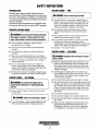
CALIFORNIA
PROPOSITION 65 WARNING
Diesel engine exhaust and some
of its constituents are known to
the State of California to cause
cancer, birth defects, and other
reproductive harm.
A WARNING:
Exhaust gasses contaIn Carbon Monoxide, an odorless and
colorless gas. Carbon Monoxide is poisonous and can cause
unconsciousness and death. Symptoms of Carbon Monoxide
exposure can include:
- Throbbing in Temples
- Dizziness
-Nausea
- Muscular Twitching
-Headache
- Vomiting
- Weakness and Sleepiness -Inability to Think Coherently
IF YOU OR ANYONE ELSE EXPERIENCE ANY OF THESE SYMPTOMS,
6ET OUT INTO THE FRESH AIR IMMEDIATELY. If symptoms persist,
seek medical attention. Shut down the unit and do not restart
until It has been inspected and repaired.
This WARNING DECAL is provided by
WESTERBEKE and should be fixed to a
bulkhead near your engine Dr generator.
WfSTERBEKE also recommends installing
CARBON MONOXIDE DETECTORS in the
living/sleeping quarters of your vessel.
They are inexpensive and easily
obtainable at your local marine store.
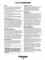
SAFETY INSTRUCTIONS
PREVENT BURNS - FIRE
INTRODUCTION
Read this safety manual carefully. Most accidents are
caused by failure to follow fundamental rules and precautions. Know when dangerous conditions exist and take the
necessary precautions to protect yourself, your personnel,
and your machinery.
The following safety instructions are in compliance with
the American Boat and Yacht Council (ABYC) standards.
•
PREVENT ELECTRIC SHOCK
•
A WARNING: Fire can cause injury Of death!
A WARNING: Do not touch AC elsctrical connections
•
whIle engIne Is runnIng, or when connected to shore
power. Lethal voltage Is present at these connections!
•
•
Do not operate this machinery without electrical
enclosures and covers in place.
•
•
•
•
•
•
chances of fire. Wipe up all spilled fuel and engine oiL
Shut off electrical power before accessing electrical
equipment.
Use insulated mats whenever working on electrical
equipment.
Make sure your clothing and skin are dry, not damp
(particularly shoes) when handling electrical equipment.
Remove wristwatch and all jewelry when working on
electrical equipment.
Do not connect utility shore power to vessel's AC
circuits, except through a ship-to-shore double throw
transfer switch. Damage to vessel's AC generator may
result if this procedure is not followed.
Electrical shock results from handling a charged capacitor. Discharge capacitor by shorting terminals together.
•
A WARNING: ExplosIons from fuel vapors can cause
injury Of death!
•
Follow re-fueling safety instructions. Keep the vessel's
hatches closed when fueling. Open and ventilate cabin
after fueling. Check below for fumes/vapor before running the blower. Run the blower for four minutes before
starting your engine.
• All fuel vapors are highly explosive. Use extreme care
when handling and storing fuels. Store fuel in a well-ventilated area away from spark-producing equipment and
out of the reach of children.
• Do not fill the fuel tank(s) while the engine is running.
• Shut off the fuel service valve at the engine when servicing
the fuel system. Take care in catching any fuel that might
spilL DO NOT allow any smoking, open flames, or other
sources of fire near the fuel system or engine when servicing. Ensure proper ventilation exists when servicing the
fuel system.
• Do not alter or modify the fuel system.
• Be sure all fuel supplies have a positive shutoff valve.
• Be certain fuel line fittings are adequately tightened and
free of leaks.
• Make sure a fire extinguisher is installed nearby and is
properly maintained. Be familiar with its proper use.
Extinguishers rated ABC by the NFPA are appropriate
for all applications encountered in this environment.
A WARNING: DD nDt touch hot engine parts Dr
exhaust system components. A runnIng engIne gets
very hot!
Always check the engine coolant level at the coolant
recovery tank.
A WARNING: Steam can cause Injury Dr death!
•
Be aware - diesel fuel will burn.
PREVENT BURNS - EXPLOSION
PREVENT BURNS - HOT ENGINE
•
Prevent flash fires. Do not smoke or permit flames or
sparks to occur near the carburetor, fuel line, filter, fuel
pump, or other potential sources of spilled fuel or fuel
vapors. Use a suitable container to catch all fuel when
removing the fuel line, carburetor, or fuel filters.
Do not operate with a Coast Guard Approved flame
arrester removed. Backfire can cause severe injury or
death.
Do not operate with the air cleaner/silencer removed.
Backfire can cause severe injury or death.
Do not smoke or permit flames or sparks to occur near
the fuel system. Keep the compartment and the
engine/generator clean and free of debris to minimize the
In case of an engine overheat, allow the engine to cool
before touching the engine or checking the coolant.
Engines & Generators
i
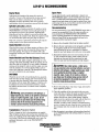
SAFETY INSTRUCTIONS
TOXIC EXHAUST GASES
ACCIDENTAL STARTING
A WARNING: Accidental starting can cause Injury
A WARNING: carbon monoxide (CO) is a deadly gas!
or death!
•
•
•
•
Disconnect the battery cables before servicing the engine!
generator. Remove the negative lead first and reconnect
it last.
Make certain all personnel are clear of the engine before
starting.
Make certain all covers, guards, and hatches are reinstalled before starting the engine.
•
•
BAnERY EXPLOSION
•
A WARNING: Banery explosion can cause injury
Ensure that the exhaust system is adequate to expel gases
discharged from the engine. Check the exhaust system
regularly for leaks and make sure the exhaust manifolds
are securely attached and no warping exists. Pay close
attention to the manifold, water injection elbow, and
exhaust pipe nipple.
Be sure the unit and its surroundings are well ventilated.
In addition to routine inspection of the exhaust system,
install a carbon monoxide detector. Consult your boat
builder or dealer for installation of approved detectors.
For additional information refer to ABYC T-22 (educational information on Carbon Monoxide).
or death!
•
•
•
•
A WARNING: carbon monoxide (CO) is an invisible
Do not smoke or allow an open flame near the battery
being serviced. Lead acid batteries emit hydrogen, a
highly explosive gas, which can be ignited by electrical
arcing or by lit tobacco products. Shut off all electrical
equipment in the vicinity to prevent electrical arcing during servicing.
Never connect the negative (-) battery cable to the positive (+) connection terminal of the starter solenoid. Do
not test the battery condition by shorting the terminals
together. Sparks could ignite battery gases or fuel vapors.
Ventilate any compartment containing batteries to prevent
accumulation of explosive gases. To avoid sparks, do not
disturb the battery charger connections while the battery
is being charged.
Avoid contacting the terminals with tools, etc., to prevent
burns or sparks that could cause an explosion. Remove
wristwatch, rings, and any other jewelry before handling
the battery.
Always tum the battery charger off before disconnecting
the battery connections. Remove the negative lead first
and reconnect it last when disconnecting the battery.
odorless gas. Inhalation produces nu-like symptoms,
nausea Dr death!
•
•
•
BAnERYACID
A WARNING: SulfuriC acid In banerles can cause
severe injury or death!
•
Do not use copper tubing in diesel exhaust systems. Diesel
fumes can rapidly destroy copper tubing in exhaust systerns. Exhaust sulfur causes rapid deterioration of copper
tubing resulting in exhaust/water leakage.
Do not install exhaust outlet where exhaust can be drawn
through portholes, vents, or air conditioners. If the engine
exhaust discharge outlet is near the waterline, water could
enter the exhaust discharge outlet and close or restrict the
flow of exhaust. Avoid overloading the craft.
Although diesel engine exhaust gases are not as toxic as
exhaust fumes from gasoline engines, carbon monoxide
gas is present in diesel exhaust fumes. Some of the symptoms or signs of carbon monoxide inhalation or poisoning
are:
Vomiting
Dizziness
Throbbing in temples
Muscular twitching
Intense headache
Weakness and sleepiness
AVOID MOVING PARTS
When servicing the battery or checking the electrolyte
level, wear rubber gloves, a rubber apron, and eye protection. Batteries contain sulfuric acid which is destructive.
If it comes in contact with your skin, wash it off at once
with water. Acid may splash on the skin or into the eyes
inadvertently when removing electrolyte caps.
A WARNING: Rotating parts can cause Injury
or death!
•
Do not service the engine while it is running. If a situation arises in which it is absolutely necessary to make
operating adjustments, use extreme care to avoid touching moving parts and hot exhaust system components.
Engines & Generators
ii
SAFETY INSTRUCTIONS
ABYC, NFPA AND USCG PUBLICATIONS FOR
INSTALLING DIESEL ENGINES
•
Do not wear loose clothing or jewelry when servicing
equipment; tie back long hair and avoid wearing loose
jackets, shirts, sleeves, rings, necklaces or bracelets that
could be caught in moving parts.
• Make sure aU attaching hardware is properly tightened.
Keep protective shields and guards in their respective
places at all times.
• Do not check fluid levels or the drive belt's tension while
the engine is opemting.
• Stay clear of the drive shaft and the transmission coupling
when the engine is running; hair and clothing can easily
be caught in these rotating parts.
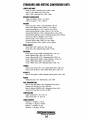
Read the following ABYC, NFPA and USCG publications
for safety codes and standards. Follow their recommendations when installing your engine.
ABYC (American Boat and Yacht Council)
"Safety Standards for Small Craft"
Order from:
ABYC
15 East 26th Street
New York, NY 10010
NFPA (National Fire Protection Association)
"Fire Protection Standard for Motor Craft"
Order from:
National Fire Protection Association
11 Tracy Drive
Avon Industrial Park
Avon, MA 02322
USCG (United States Coast Guard)
"USCG 33CFR183"
Order from:
U.S. Government Printing Office
Washington, D.C. 20404
HAZARDOUS NOISE
A WARNING: High nol$8 levels can cause hearing
loss!
•
•
•
Never operate an engine without its muffler installed.
Do not run an engine with the air intake (silencer)
removed.
Do not run engines for long periods with their enclosures
open.
A WARNING: Do not work on machinery when you are
mentally Dr physically incapacitated by fatigue!
OPERATORS MANUAL
Many of the preceding safety tips and warnings are repeated
in your Operators Manual along with other cautions and
notes to highlight critical information. Read your manual
carefully. maintain your equipment. and follow all safety
procedures.
ENGINE INSTALlATIONS
Preparations to install an engine should begin with a thorough examination of the American Boat and Yacht Council's
(ABYC) standards. These standards are a combination of
sources including the USCG and the NFPA
Sections of the ABYC standards of particular interest are:
H-2 Ventilation
P-l Exhaust systems
P-4 Inboard engines
E-9 DC Electrical systems
All installations must comply with the Federal Code of
Regulations (FCR).
Engines & Generators
iii
INSTALLATION
When installing WES1ERBEKE engines and generators it is important that strict
attention be paid to the following information:
CODES AND REGULATIONS
Strict federal regulations, ABYC guidelines, and safety codes must be complied with
when installing engines and generators in a marine environment.
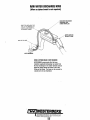
SIPHON-BREAK
For installations where the exhaust manifold/water injected exhaust elbow is close to
or will be below the vessel's waterline, provisions ~ be made to install a siphonbreak in the raw water supply hose to the exhaust elbow. This hose must be looped a
minimum of 20" above the vessel's waterline. Failure to use a siplwn-break when
the exhaust manifold injection port is at or below the load waterline will result in
raw water damage to the engine and possible flooding of the boat.
If you have any doubt about the position of the water-injected exhaust elbow relative
to the vessel's waterline under the vessel's various operating conditions, install a
siphon-break.
NOTE: A siphon-break requires periodic inspection and cleaning to ensure proper
operation. Failure to properly maintain a siphon-break can result in catastrophic
engine damage. Consult the siphon-break manufacturer for proper maintenance.
EXHAUST SYSTEM
The exhaust hose must be certified for marine use. The system must be designed to
prevent water from entering the exhaust under any sea conditions and at any angle
of the vessels hull.
A detailed 40 page Marine Installation Manual covering gaSOline and
diesel, engines and generators, is available from Jour WESTERBEKE
dealer.
/w-/WESTERBEKE
I En9ines & Generators
iv
TABLE OF CONTENTS
Glow Plugs .........................................................24
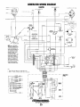
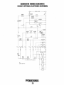
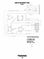
Generator Wiring Diagram .................................25
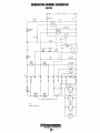
Generator Wiring Schematic .............................26
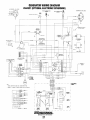
Generator Wiring Diagram
Parts Identification .............................................2
Introduction .........................................................3
Warranty Procedures ...................................... 3
Serial Number Location ............................... .4
Diesel Fuel,. Engine Oil and Coolant.. .................5
(with Electronic Governng) ......................... 27
Generator Wiring Schematic
Generator Control- Panels ....................................6
(with Electronic Schematic) ........................ 28
Description of Switches ................................. 6
Description of Gauges ...................................6
Remote Panel .................................................6
Remote Instrument Panel .................................29
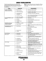
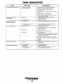
Engine Troubleshooting (Chart) .......................30
Control Panel Troubleshooting ......................... 32
Engine Adjustments ...........................................33
Preparations for Initial Start·Up .........................7
Pre-Start Inspection .......................................7
Generator Voltage .......................................... 7
Drive Belt Adjustment ................................ .33
Electronic Governor (Optional) .................. .33
Engine Speed/Engine Shutdown ................ .33
Valve Clearance .......................................... .34
Testing Engine Compression.......................35
Fuel Injectors ...............................................35
Generator Information .......................................36
BT Generator .....................................................37
Internal Wiring (6 Stud) ..............................38
Starting/Stopping Procedure...............................8
Safety Shutdown Switches ............................ 9
Generator Break·ln Procedure ..........................1 0
The Daily Operation ........................................... 11
Maintenance Schedule ..................................... 12
Cooling System .................................................. 14
Changing Coolant ........................................ 14
Thermostat ................................................... 15
Raw Water Cooling Pump ........................... 15
Changing the Raw Water Impeller .............. 16
Heat Exchanger ........................................... 16
Air IntakelSilencer ............................................ 17
Air Filter ...................................................... 17
Fuel System ....................................................... 18
Fuel LiftlWater Separator ............................ 18
Fuel Lift Pump ............................................. 18
Fuel Lift Pump Filter ................................... 18
Fuel Filter .................................................... 18
Engine Lubricating Oil ....................................... 19
Engine Oil Change ...................................... 19
Oil Pressure .......................................................20
Testing Oil Pressure ..................................... 20
Remote Oil Filter ...............................................21
Generator Voltage Adjustment .........................39
Automatic Voltage Regulator ..................... .40
Voltage Regulator Adjustments .................. .40
Generator Internal Wiring ................................ .41
Regulator Sensing 3 Phase ..............................42
Shore Power Transfer Switch ............................43
Generator Troubleshooting (Chart) ...................44
Lay·Up and Recommissioning .......................... .45
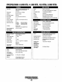
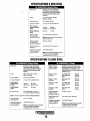
Specifications (3 Cylinder Engine) ................... .47
8.0/6.0Kw . 10.0n .5Kw ................................... .48
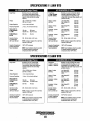
11.5/9.2Kw .. 12.6/10.4Kw .............................. ..49
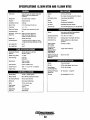
Specifications (4 Cylinder Engine) ...............:.... 50
12.5/9.4Kw· 15.0/12.0Kw ................................ 51
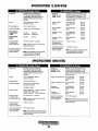
Engine Torque Specifications ...........................52
Standard Hardware ............................................53
Metric Conversion Data ....................................55
Raw Water Discharge Hose ...............................56
Power Take Off System .....................................57
Suggested Spare Parts ......................................58
DC Electrical System .........................................22
Alternator Troubleshooting ......................... 22
Battery Care ................................................. 23
Engines & Generators
1
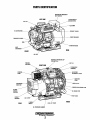
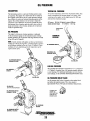
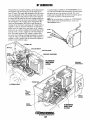
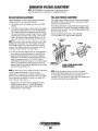
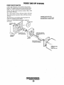
PARTS IDENTIFICATION
GENERATOR EMERGENCY
STOP SWITCH
LEFT SIDE
CONNECTION TO
BREAK
OIL FI
to.PlATE
DC
'--"~-I----+---EXHAUST
ELBOW
SOLENOID
STARTER MOTOR
REAR
FRONT
OIL PAN
MANIFOLD PRESSURE CAP
.FILL
PREHEAT
'FILL
RIGHT SIDE
THERMOSTAT
ASSEMBLY
AIR INTAKE
SILENCER & FILTER
_---INJECTION
PUMP
ENGINE BLOCK DRAIN PLUG
20 AMP
CIRCUIT
BREAKER
FILTER
BREAKER
FRONT
REAR
MOUNT
Engines & Generators
2
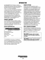
INTRODUCTION
PRODUCT SOFTWARE
lhis WESTERBEKE Diesel Generator is a product of
WESTERBEKE's long years of experience and advanced
technology. We take great pride in the superior durability and
dependable performance of our engines and generators.
Thank you for selecting WESTERBEKE.
In order to get the full use and benefit from your generator it
is important that you operate and maintain it correctly. lhis
manual is designed to help you do this. Please read this
manual carefully and observe all the safety precautions
throughout. Should your generator require servicing, contact
your nearest WESTERBEKE dealer for assistance.
This is your operators manual. A parts catalog is also
provided and a technical manual is available from your
WESTERBEKE dealer. If you are planning to install this
equipment contact your WESTERBEKE dealer for
WESTERBEKE'S installation manual.
Your WESTERBEKE Warranty is included in a separate
folder. If, after 60 days of submitting the Warranty Registry
form you have not received a customer identification card
registering your warranty, please contact the factory in
writing with model information, including the unit's serial
number and commission date.
Product software, (tech data, parts lists, manuals,
brochures and catalogs), provided from sources other than
WESTERBEKE are not within WESTERBEKE's control.
WESTERBEKE CANNOT BE RESPONSIBLE FOR TIlE
CONTENT OF SUCH SOFTWARE, MAKES NO WARRANTIES OR REPRESENTATIONS WITH RESPECT
THERETO, INCLUDING ACCURACY, TIMEUNESS OR
COMPLETENESS THEREOF AND WILL IN NO EVENT
BEUABLE FOR ANY TYPE OF DAMAGE OR INJURY
INCURRED IN CONNECTION WITH OR ARISING OUT
OF THE FURNISHING OR USE OF SUCH SOFTWARE.
WESTERBEKE customers should also keep in mind the
time span between printings of WESTERBEKE product
software and the unavoidable existence of earlier
WESTERBEKE manuals. In summation, product software
provided with WESTERBEKE products, whether from
WESTERBEKE or other suppliers, must not and cannot
be relied upon exclusively as the definitive authority on
the respective product. It not only makes good sense
but is imperative that appropriate representatives of
WESTERBEKE or the supplier in question be consulted
to determine the accuracy and currentness of the
product software being consulted by the customer.
Customer Identification Card
NOTES, CAUTIONS AND WARNINGS
WARRANTY PROCEDURES
As this manual takes you through the operating procedures,
maintenance schedules, and troubleshooting of your marine
engine, critical information will be highlighted by NOTES,
CAUTIONS, and WARNINGS. An explanation follows:
,....".",WESTERBEKE
, Engines & Generators
Customer Identification
MR. GENERATOR OWNER
MAIN STREET
HOMETOWN, USA
Model 15 BTC
Ser. #
Expires
NOTE: An operating procedure essential to note.
A CAUTION: Procedures, which if not stTictly
observed, can result In the damage Dr destruction of
your engine.
A WARNING: Procedures, which if not properly fol-
The WESTERBEKE serial number is an alphanumeric
number that can assist in determining the date of manufacture of your WESTERBEKE engine or generator. The manufacturer's date code is placed at the end of the engine serial
number and consists of a character followed by three
numbers. The character indicates the decade.
lowed, can rssult in personal Injury or lOss of me.
Engines & Generators
3
INTRODUCTION
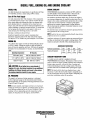
NOTE: A carbon monoxide warning decal has been provided
by WESTERBEKE. Affix this decal in a visible position in the
engine room.
SERIAL NUMBER LOCATION
The engine and generator serial numbers and model numbers
are located on a decal on~the generator housing. Take the
time to enter the information on the blank decal provided
below as this will provide a quick reference when seeking
technical information andlor ordering repair parts.
UNDERSTANDING THE DIESEL ENGINE
The diesel engine closely resembles the gasoline engine,
since the mechanism is essentially the same. The cylinders
are arranged above a closed crankcase; the crankshaft is of
the same general type as that of a gasoline engine; and the
diesel engine has the same types of valves, camshaft, pistons,
connecting rods and lubricating system.
Therefore, to a great extent, a diesel engine requires the
same preventive maintenance as a gasoline engine. The
most important factors are proper ventilation and proper
maintenance of the fuel, lubricating and cooling systems.
Replacement of fuel and lubricating filter elements at the
time periods specified is a must, and frequent checking for
contamination (that is, water, sediment, etc.) in the fuel
system is also essential. Another important factor is the use
of the same brand of high detergent diesel lubrication oil
designed specifically for diesel engines.
The diesel engine does differ from the gasoline engine,
however, in its method of handling and firing of fuel. The
carburetor and ignition systems are done away with and in
their place is a single component the fuel injection pump which performs the function of both.
~
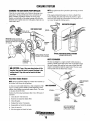
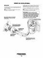
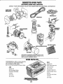
ORDERING PARTS
Whenever replacement parts are needed, always provide the
generator model number, engine serial number, and generator
serial number as they appear on the silver and black name
plate located on the generator end. You must provide us with
this information so we may properly identify your generator
set. In addition, include a complete part description and part
number for each part needed (sec the separately furnished
Partl! List): Also insist upon WESTERBEKE packaged parts
because will fit or generic parts are frequently not made to
the same specifications as original equipment.
The engine serial number can also be found stamped into the
engine block just above the injection pump. The generator
serial number is stamped into the generator housing on the
flat surface on the left side of the generator.
Il:n
:R!!i!i.!:2!)
~,~
..
SPARES AND ACCESSORIES
Certain spares will be needed to support and maintain your
WESTERBEKE generator. Your loeal WESTERBEKE
dealer will assist you in preparing an inventory of spare parts.
See the SPARE PARTS page in this manual. For Engine and
Generator Accessories, see the ACCESSORIES brochure.
-,
An identification plate on the engine manifold also displays
the engine model and serial number.
GENERATOR
ID DECAL
SERIAL
NUMBER
Engines & Generators
4
DIESEL FUEL, ENGINE OIL AND ENGINE COOLANT
DIESEL FUEL
ENGINE COOLANT
Use fuel that meets the requirements or speeification of Class
2-D (AS1M), and has a cetane rating of #45 or better.
WESTERBEKE reeommends a mixture of 50% antifreeze
and 50% distilled water. Distilled water is free from the
chemicals that can corrode internal engine surfaces.
The antifreeze perfonns double duty. It allows the engine to
run at proper temperatures by transferring heat away from the
engine to the coolant, and lubricates and protects the cooling
circuit from rust and corrosion. Look for a good quality
antifreeze that contains Supplemental Cooling Additives
(SCAs) that keep the antifreeze chemically balanced, crucial
to long tenn protection.
The distilled water and antifreeze should be premixed before
being poured into the cooling circuit.
Care Of The Fuel Supply
Use only clean diesel fuel! The clearance of the components
in your fuel injeetion pump is very critical; invisible dirt particles which might pass through the filter can damage these
finely finished parts. It is important to buy clean fuel, and
keep it clean. The best fuel can be rendered unsatisfactory by
careless handling or improper storage facilities. To assure that
the fuel going into the tank for your engine's daily use is
clean and pure, the following practice is advisable:
Purchase a well-known brand of fuel.
Install and regularly service a good, visual-type fuel
filter/water separator between the fuel tank and the engine.
The Rayeor 225 or 500MA are good examples of such filters.
NOTE: Look for the new environmentally-friendly long lasting
antifreeze that is now available.
Antifreeze mixtures will protect against an unexpected freeze
and they are beneficial to the engine's cooling system. They
retard rust and add to the life of the circulating pump seal.
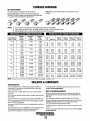
ENGINE OIL
Use a heavy duty engine oil with an API classification of CF
or CG-4 or better. Change the engine oil after an initial 50
hours of break-in operation, and every 100 hours of operation
thereafter. For reeommended oil viscosity, see the following
chart:
Operating TemperabJre
011 Viscosity
Above 68°F (20°C)
SAE 30, 10W-30 or 15W-40
41 ° - 68°F (5 - 20°C)
SAE 20, 10W-30 or 1SW-40
Below 41°F (SOC)
SAE 10W-30 or 15W-40
ANTIFREEZE PROTECTION
Antifreeze Concentration
Freezing Temperature
23%
14·F
(-10°C)
30%
8·F
(-13·C)
35%
-4°F
(-20·C)
50%
COOLANT RECOVERY TANK
A coolant recovery tank kit is supplied with each
WESTERBEKE diesel engine. The purpose of this recovery
tank is to allow for engine coolant expansion and contraction
during engine operation, without the loss of coolant and
without introducing air into the cooling system. This kit is
provided and must be installed before operating the engine.
A CAUTION: Do not allow two or more brands of
engine oil to mix. Each brand contains Its own additives;
additives of diffefent brands could feact in the mixture
to produce properties harmful to your engine.
NOTE: This tank, with its slwrt run of plastic hose, is best
located at or above the level of the engine's manifold, but it
can be located below the level of the engine's manifold if the
particular installation makes this necessary.
OIL PRESSURE
The engine's oil pressure, during operation, is indicated
by the oil pressure gauge on the instrument panel. During
nonnal operation, the oil pressure will range between 35 and
55 psi (2.5 and 3.9 kg/cm 2).
NOTE: A newly started, cold engine can have an oil pressure
reading up to 60 psi (4.2 kg!cm2). A wanned engine can have
an oil pressure reading as low as 25 psi (1.8 kglcm 2). These
readings will vary depending upon the temperature of the
engine, the load placed on the engine, and the RPM's.
Engines & Generators
5
GENERATOR CONTROL PANELS
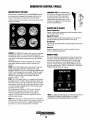
DESCRIPTION OF SWITCHES
EMERGENCY STOP: The EMERGENCY
stop switch on the side of the control box,
is normally closed. When depressed, it
will open the DC circuit to the control
panel and shut the engine down. As the
switch is not toggled it can -be used when
performing maintenance.
This manually controlled series ofWESTERBEKE marine
diesel generators is equipped with toggle switches on the
engine control panel and, optionally, at remote panels.
All three switches are momentary contact type and serve the
following functions:
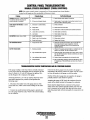
DESCRIPTION OF GAUGES
Coolant Temperature
Engine coolant (water) temperature should normally indicate
1750 to 1950 F (800 to 90° C).
Engine 011 Pressure
Oil pressure (psi) may fluctuate depending on the generator
load but should range between between 30 to 60 psi.
DC Voltm8t8r
Indicates the amount the battery is being charged should show
13Vto 14V.
Hourmeter
Registers elapsed time and is used as a guide for when to
perform scheduled maintenance.
PREHEAT: The PREHEAT toggle switch serves two purposes:
preheating the engine for easy starting and defeating of
bypassing the engine oil pressure switch. The defeat function
turns on the fuel solenoid, instrument power and alternator
excitation.
When the PREHEAT switch is depresseq, the voltmeter,
panel lights, gauges and meters and fuel solenoid will
activate.
START: The START toggle switch closes the Kl relay that
energizes the starter solenoid and activates the starter..
While the PREHEAT switch is still depressed, depressing the
START switch engages the start solenoid. When the engine
begins to fire, the START switch should be released. The
PREHEAT switch should not be released until the oil
pressure reaches 5 - 10 psi.
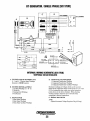
REMOTE PANEL
For remote operation of the generator system, the same three
switches are used. The PREHEAT and START switches are
connected in parallel with the gauge panel's switches and
serve the same functions as in the gauge panel. The STOP
switch is in series with the gauge panel's STOP switch and
serves the same function. There is a REMOTE START/STOP
WIRING DIAGRAM in this manual.
GENERATOR
RELEASE
providing power to the fuel solenoid, instrument cluster and
alternator excitation, after the oil pressure switch has closed
upon starting. Opening of this switch opens the power circuit
to the fuel solenoid, stopping the flow of fuel to the engine
and shuts down the engine.
To stop the engine, depress the STOP switch. When the
STOP switch is depressed, the power feed to the fuel
solenoid is opened, and the fuel flow to the engine is
stopped. The STOP switch should be depressed until the
generator stops rotating.
STOP
PREHEAT
START
MUST
PRESS
1ST
CI'
STARTER
STOP: The STOP toggle switch is a normally closed switch.
~
t:t)~
==
1ft!).
\' '1/
PRESS
2 ND
WESTERSEKE
NOTE: For additional infOnnalion on Control Panels. Refer to:
STARTING/STOPPING PROCEDURE, DC WIRING
DIAGRAMS and TROUBLESHOOTING GAUGES.
NOTE: When the engine is shut down, the water temperature
gauge and the oil pressure gauge will continue to register the
last temperature and oil pressure readings displayed. They
will return to zero once electrical power is restored.
Engines & Generators
6
I
PREPARATIONS FOR INITIAL START-UP
PRESTARTINSPECTIO~
A CAUTION: When starling the generator, it is
This section of the manua provides the operator with preparation, initial starting, bre -in, starting (warm or cold) and
stopping procedures. Foil w the procedures as presented for
the conditions indic
your WESTERBEKE generator
set will give reliable pem
ance and long service life.
recommended that aI/ AC loads, especially large motors,
be switched OFF until the engine has come up to speed
and, In cold climates, starts to warm up. This precaution
will prevent damage caused by unanticipated operation
of the AC machinery and will prevenl a cold engine from
slalling.
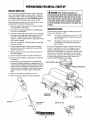
Before starting your generator set for the first time or after a
prolonged layoff, check th~ following items:
D Check the engine oil level. Add oil to maintain the level
at the high mark on thf dipstick.
Check the fuel supply Md examine the fuel filter/separator bowls for contarnil1ants.
GENERATOR VOLTAGE
The speed of the generator engine is adjusted at the factory,
however, it is advisable to verify.
Check the DC electric~l system. Inspect wire connections
and battery cable connbctions. Make certain the (+) battery cable is connecteq to the starter solenoid and the
negative (-) cable iS~'nnected to the engine ground stud
(this location is tagg .
.
60 Hz
50Hz
Check the coolant lev 1in both the plastic recovery tank
and at the manifold. '
D Visually examine the lll1it. Look for loose or missing
The speed of the generator engine is adjusted at the factory,
however it is advisable to verify. The voltages are easily
adjusted to optimum values no-load and full load (refer to
VOLTAGE ADJUSTMENT in this manual). If possible, apply
actual service or test load of the same power factor as the
load to be used in service. If the voltage cannot be adjusted
to suitable values and fault seems evident, contact your
authorized
.
parts, disconnected w+'i es, unattached hoses, and check
threaded connections.
Check load leads for c rrect connection as specified in
the wiring diagrams.
Examine air inlet and 'l}Utlet for air flow obstructions.
D
D Be sure no other gene~ator or utility power is connected
to load lines.
The engine no-load speed is set at 61.5 - 62 Hz.
At rated amperage hertz output may decrease to
48.6 - 59.0 Hz.
The engine no-load speed is set at 61.5 Hz. At
rated amperage hertz output may decrease to
48.5 - 49.0 Hz.
I
D Be sure that in power hstems with a neutral line that
the neutral is properltOUnded (or ungrounded) as the
system requires, and at the generator neutral is properly
connected to the load eutral. In single phase and some
3-phase systems an indomplete or open neutral can supply the wrong line-to-qeutral voltage on unbalanced
'
loads.
rm:.'''''Ulru:
Make sure the mounting installation is secure.
Make sure that the generator is properly grounded.
GLOW
CONNECTION
Oil FILL CAP
DIPSTICK~
~
---\
~ \\ \\ APPROXIMATELY
\
OIL LEVEL \
SIDE OIL FILL CAP
ONE QUART
~.
Engines & Generators
7
CAP
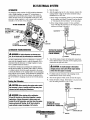
STARTING/STOPPING PROCEDURE
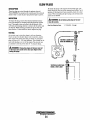
THE STARTING SYSTEM
Westerbeke diesel generators use electric starters assisted by
glow plugs for both normal and cold weather starting. The
illustration below shows a cross-sectional view of one cylinder. The glow plug is located in the combustion chamber so
that its tip is in the injector nozzle's spray path. When the
glow plug is energized by the PREHEAT button, the plug
glows red at the tip and assists in igniting the fuel. The result
is a rapid start with less wear on the starter.
This system is common to WESTERBEKE diesels. The start
circuitry is designed so that the PREHEAT button must be
depressed fOf the time specified in the preheat chart. Then,
while keeping the PREHEAT button engaged, the START
button is depressed to crank the engine.
NOTE: The START switch will not energize unless the PREHEAT switch is depressed. Depressing the PREHEAT switch
activates the glow plugs in the cylinder head so use the PREHEAT intermittently to avoid overheating the glow plugs.
Should the engine not start when the START switch is
depressed for 10 to 20 seconds, release both switches and
wait 30 seconds; repeat the procedure above and preheat
longer. Never run the starter for more than 30 seconds.
A
CAUTION: Prolonged cranking intervals without the
engine stanlng can result In the engine exhaust system
filling with raw water. This may happen because the
pump is pumping raw water through the raw water CODling system during cranking. This raw water can enter the
engine's cylinders by way of the exhaust manifold once
the exhaust system nils. Prevent this from happening by
closing the raw water supply through-hull shut-off,
draining the exhaust muffler. and correcting the cause
of the excessive engine cranking. Engine damage resulting from raw water entry is not a warrantablelssuej the
owner/operator should keep this In mind.
.
Remote Starting Procedure
GLOW PLUG
PREHEAT: Depress the PREHEAT switch. The voltmeter and
panel lights, gauges and meters will be activated. The PREHEAT switch should be depressed in accordance with the
following chart:
TemperatureJPreheat
Abnospheric Temperature
Preheating Time
+41 °F(+5°C) or higher
Approx. 10 seconds
+41°F(+5°C) to 23°F (-5°C)
Approx. 15 seconds
+23°F( -5°C) or lower
Limit of continuous use
Approx. 20 seconds
30 seconds before cranking
START: While still depressing the PREHEAT switch, depress
the START switch. This will engage the starter solenoid.
Upon engine starting, release the START switch. Do not
release the PREHEAT switch until the oil pressure reaches.
5 - 10 psi. Then as long as the high water temperature and
low oil pressure protective circuits do not activate. the engine
will remain energized and continue to run.
NOTE: When starting:
A voltage drop will occur
when the prelfleat switch
is depressed:
The remote start panel is the same as the engine-mounted
start panel except that it has a green LED light and no
gauges. When starting at a remote location, the green LED
lights when the generator is running at approximately 600
rpm. This indicates when the START switch can be released
since the starting of the generator may not be audible.
A. When the PREHEAT switch is depressed at the remote
start/stop panel the LED light will illuminate. When the
START switch is depressed and the starter cranks the
engine this LED light will dim. When the engine starts
the LED light will brighten signaling to release the
START switch. Continue to hold the PREHEAT
depressed for a few seconds to allow oil pressure to build
up which closes the oil pressure safety switch that is in
the series path for I2V B+ to the fuel run solenoid. The
green LED will remain brightly illuminated while the
engine is running.
B. After the generator is started and the START switch is
released, the generator's starter will not crank unless the
PREHEAT switch is operated first because this switch
supplies voltage to the START switch.
Once the engine starts, check the engine's instruments for
proper oil pressure and battery charging voltage. Apply a
light'Ioad to the generator and allow the engine's operating
temperature to come up to 140-150° (60-66° C) before
applying heavy loads.
NOTE: Some unstable running may occur in a cold engine.
Depressing the PREHEAT switch/or 10-15 second intervals
will help stabilize the engine rpm until the operating
temperature reaches 140 - 150 0 F and a load is applied to
the engine.
lW-IWESTERBEKE
I Engines & Generators
\// 8
STARTING/STOPPING PROCEDURE
STARTING UNDER COLD CONDITIONS
Coolant Temperature Switch
Make sure the lubricating oil confonns with the ratings for
the prevailing temperature. Check the table in the ENGINE
OIL section in this manuaL
A high coolant temperature switch is located on the thennostat
housing. Nonnally closed, this switch, should the fresh water
coolant's operating temperature reach approximately 210°F
(99°C), will open and interrupt the DC voltage to the K2
relay, thereby shutting off the engine. This switch resets at
195°F (107°C).
The battery should be fully charged to minimize voltage
drop.
Use a sufficient amount of preheat to aid in starting. See the
TemperaturelPreheat chart on the previous page.
STOPPING PROCEDURE
1. Remove the AC electrical load from the generator and
allow the generator to run for three to five minutes to
stabilize its operating temperatures.
COOLANT
TEMPERATURE
SWITCH
2. Depress the STOP switch and hold it until the generator
is completely stopped.
3. Now release the STOP switch.
Remote Stopping Procedure
To stop the generator, depress the STOP switch which opens
the nonnally closed B+ path for voltage to the engine's run
-circuit. The STOP switch must be held open until the
generator comes to a complete stop and the green LED light
goes out.
.
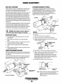
Low Oil Pressure Switch
A low oil pressure shutdown switch is located off the engine's
oil gallery. Nonnally open in a static state, this switch's sensor
monitors the engine's oil pressure. Should the engine's oil
pressure fall to 5-10 psi, this switch will open interrupting the
DC voltage to the K2 relay, thereby shutting off the engine.
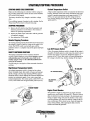
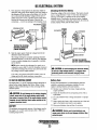
SAFETY SHUmOWN SWITCHES
The engine is protected by three automatic shutdown
switches. Should shutdown occur, do not attempt to restart
without finding and correcting the cause. Refer to the
heading "Engine Stops" in the TROUBLESHOOTING
section of this manual.
The following is a description of these automatic shutdown
switches:
High Exhaust Temperature Switch
An exhaust temperature switch is located on the exhaust
elbow. Nonnally closed, this switch will open and interrupt
the DC voltage to the K2 relay (shutting OFF the engine)
should the switch's sensor indicate an excessive exhaust temperature (an inadequate supply of raw water causes high
exhaust temperatures). This switch opens at 260-270°F (127132°C). This switch resets at approximately 225°F (l07°C).
OIL PRESSURE SWITCH
OIL PRESSURE /
SENDOR
/
EXHAUST ELBOW
Engine Circuit Breaker
HIGH EXHAUST
TEMPERATURE
SWITCH
The generator's engine is protected by an engine moun~
manual reset circuit breaker (20 amps DC). Excessive current
draw or electrical overload anywhere in the instrument panel
wiring or engine wiring will cause the breaker to trip. In this
event the generator will shut down and the voltage to the K2
relay is terminated. If this should occur, check and repair the
source of the problem. After repairing the fault, reset the
breaker and restart the generator.
~ ~tra.::=~
I'
r
Engines & Generators
9
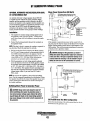
GENERATOR BREAK-IN PROCEDURE
CHECK THE FOLLOWING
DESCRIPTION
o Monitor the control panel gauges.
Although your engine has experienced a minimum of one
hour of test operations at the factory to make sure accurate
assembly procedures were followed and that the engine
operated properly. a break-in time is required. The service
life of your engine is dependent upon how the engine is operated and serviced during its initial hours of use.
Check for leaks of fuel and engine oiL
Check for abnormal noise such as knocking, friction,
vibration and blow-back sounds.
o Confirm exhaust smoke:
Breaking-in a new engine basically involves seating the
piston rings to the cylinder walls. Excessive oil consumption
and smoky operation indicate that the cylinder walls are
scored, which is caused by overloading the generator during
the break-in period.
When the engine is cold - White Smoke.
When the engine is warm - almost Smokeless.
When the engine is overloaded - some Black Smoke.
To protect against unintentional overloading of the generator,
the generator's output leads should be routed through a circuit breaker that is rated at the rated output of the generator.
Your new engine requires approximately 50 hours of initial
conditioning operation to break in each moving part in order
to maximize the performance and service life of the engine.
Perform this conditioning carefully, keeping in mind the
following:
NOTE: Be aware of motor starting loads and the high current
draw required for starting motors. This starting amperage
draw can be 3 to 5 times normal running amperage. See
GENERATOR INFORMATION in this manual.
Start the engine according to the STARTING PROCEDURE
section. Run the engine while checking that all systems (raw
water pump, oil pressure, battery charging) are functioning.
GENERATOR ADJUSTMENTS
Once the generator has been placed in operation, there may
be adjustments required for engine speed (hertz) during the
engine's break-in period (first 50 hours) or after this period.
A no-load voltage adjustment may also be required in conjunction with the engine's speed adjustment. Sec
GENERATOR INFORMATION in this manual.
AFTER START-UP
Once the generator has been started, check for proper operation and then encourage a fast warm-up. Run the generator
between 20% and 60% of fun-load for the first 10 hours.
A CAUTION: 00 not attempt to bl'flak-in your
generator by running without a load.
After the first 10 hours of the generator's operation, the load
can be increased to the full-load rated output, then periodically vary the load.
Avoid overload at all times. An overload is signaled by
smoky exhaust with reduced output voltage and frequency.
Monitor the current being drawn from the generator and keep
it within the generator's rating. Since the generator operates
at 1800 rpm to produce 60 hertz (or at 1500 rpm to produce
50 Hertz), control of the generator's break-in is governed by
the current drawn from the generator.
Engines & Generators
10
THE DAILY OPERATION
CHECK LIST
START THE GENERATOR
Follow this check list each day before starting your generator.
o Record the hourmeter reading in your log (engine hours
relate to the maintenance schedule.)
(See STARTING PROCEDURES on previous pages).
Allow the engine to wann up for S to 10 minutes to reach an
operating temperature of 140° to 1S0°F (60°-66°C) before
applying AC loads. Apply loads systematically allowing the
generator to adjust to each load before applying the next.
Check the gauges for proper oil pressure, operating temperature, and DC voltage.
Visually inspect the generator for fuel, oil, or water leaks.
Check the oil level (dipstick).
o Check the coolant level in the coolant recovery tank.
NOTE: Some unstable running may occur in a cold engine.
This condition should lessen as normal operating temperature is reached and loads are applied.
o Check: your diesel fuel supply.
Look for clean fuel in the fueUseparator transparent bowL
Check for loose wires at the alternator.
A CAUTION: Do not operate the generator for long
o Check the starting batteries (weekly).
o Check drive belts for wear and proper tension (weekly).
periods of time without a load being placed on the
STOPPING THE GENERATOR
Remove the major AC loads from the generator one at a
time. Allow the generator to run for a few minutes to stabilize the operating temperature and depress the stop switch.
(See STOPPING PROCEDURES on previous pages.)
Engines & Generators
11
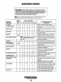
MAINTENANCE SCHEDULE
A WARNING: NBvel attBmpt to pBrfDlm any SBIV/CS wh/Is ths sngins Is
lunnlng. Wsal ths PfOPSI safBty squlpmsnt such as gogglss and glOVBS1 and
USB ths COfrsct tools fOf Bach Job. Dlsconnsct ths battsry tsrmlnals whsn
sSIV/clng any of the snglns's DC slsctrlcal squ/pmsnt.
NOTE: Many of the following maintenance jobs are simple but others are more
difficult and may require the expert knowledge of a service mechanic.
SCHEDULED
MAINTENANCE
Fuel Supply
Fuel/Water Separator
CHECK
EACH
DAY
HOURS OF OPERATION
50
100
~50
500
750 1000 1250
Diesel No.2 rating of 45 cetane or higher.
0
0
Check for water and dirt in fuel (drain/replace filter
if necessary).
Engine Oil level
Coolant Level
Drive Belts
Oil level should indicate between MAX. and LOW on
dipstick.
0
Check at recovery tank; if empty, check at manifold.
Add coolant if needed.
0
Inspect for proper tension (3/8' to 1/2" deflection)
and adjust if needed. Check belt edges for wear.
weekly
NOTE: Please keep engine surface clean. Dirt
and oil will inhibit the engine's ability to
remain cool.
Visuallnspectlon of Engine
Fuel Filter
Starting Batteries
(and House Batteries)
EXPLANATION OF SCHEDULED
MAINTENANCE
0
0
0
0
0
Check for fuel, oil and water leaks. Inspect wiring
and electrical connections. Keep bolts & nuts tight.
Check for loose belt tenSion.
Initial change at 50 hrs, then change every 250 hrs.
Every 50 operating hours check electrolyte levels
and make sure connections are very tight. Clean off
excessive corrosion.
0
weekly
Engine Oil (and filter)
0
0
0
0
0
0
0
Initial engine oil & filter change at 50 hrs., then
change both every 100 hours.
Generator
0
0
0
0
0
0
0
Check that AC connections are clean and secure
with no chafing. See GENERATOR SECTION
for additional information.
Heat Exchanger Zinc Anode
0
0
0
0
0
0
0
0
o
TOT 0
Inspect zinc anode, replace if needed, clear the heat
exchanger end of zinc anode debris.
0
0
Change every 200 hours.
Fuel/Water Separator
Electronic Governor Control
(if applicable)
Exhaust System
Engine Hoses
Check and or adjust the no-load speed in the panel,
req uired (hertz) and the regulator board adjustment
as needed.
NOTE: These adjustment are not a warrantable
adjustment during or after the unit's break-in.
0
0
0
0
0
0
D
0
0
0
0
Initial check at 50 hrs., then every 250 hrs. Inspect
for leaks. Check anti-siphon valve operation. Check
the exhaust elbow for carbon and/or corrosion
buildup on inside passages; clean and replace as
necessary. Check that all connections are tight.
0
Hose should be hard & tight. Replace if soft or
spongy. Check and tighten all hose clamps.
EngInes & Generators
12
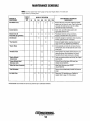
MAINTENANCE SCHEDULE
NOTE: Use the engine Iwur meter gauge to log your engine hours or record your
engine Iwurs by running time.
SCHEDULED
MAINTENANCE
CHECK
EACH
DAY
HOURS OF OPERATION
50
Raw Water Pump
100
250
0
Coolant System
Electric Fuel Lift
Pump Filter (If applicable)
500
750 1000 1250
0
0
0
DC Alternator
0
0
0
0
0
0
EXPLANATION OF SCHEDULED
MAINTENANCE
0
Remove the pump cover and inspect the impeller,
gasket, cam and cover for wear. Check the bearings
and seals (the shaft can turn, but not wobble).
Lubricate both when reassembled.
0
Drain, flush, and refill cooling system with
appropriate antifreeze mix.
0
Periodically check the wiring connections.
Replace in-line filter filter every 200 hours.
0
Check DC charge from alternator. Check mounting
bracket; tighten electrical connections.
*Fuellnjectors
Check and adjust injection opening pressure and
spray condition (see ENGINE ADJUSTMENTS).
*Starter Motor
0
0
Check solenoid and motor for corrosion. Remove
and lubricate. Clean and lubricate the starter motor
pinion drive.
*Preheat Circuit
0
0
Check operation of preheat solenoid. Remove and
clean glow plugs; check resistance (4-6 ohms).
Reinstall with anti seize compound on threads.
*Englne Cylinder
Compression
0
0
Check compression pressure and timing (see Engine
Adjustments).
*Torque Cylinder Head
Hold-down bolts
0
0
0
At first 50 hours, then every 500 hours (see
ENGINE ADJUSTMENTS).
*Adjust the Valve Clearances
0
0
0
Adjust Valve Clearances (see ENGINE
ADJUSTMENTS).
0
Remove, have professionally cleaned and pressure
tested.
"Heat Exchanger
Air Intake Filter
0
0
0
0
0
"WESTERBEKE recommends this service be performed by an authorized mechanic.
Engines & Generators
13
Clean every 100 operating hours. Replace as
needed. Refer to page 17 of this manual.
COOLING SYSTEM
When the engine is started cold, external coolant flow is prevented by the closed thermostat (although some coolant flow
is bypassed around the thermostat to prevent the exhaust
manifold from overheating). As the engine warms up, the
thermostat gradually opens, allowing full flow of the engine's
coolant to flow unrestricted to the external portion of the
cooling system.
DESCRIPTION
Westerbeke marine diesel engines are designed and equipped
for fresh water cooling. Heat produced in the engine by combustion and friction is transferred to fresh water coolant
which circulates throughout the engine. This circulating fresh
water coolant cools the engine block, its internal moving
parts, and the engine oil. The heat is transferred externally
from the fresh water coolant to raw water by means of a heat
exchanger, similar in function to an automotive radiator. Raw
water flows through the tubes of the heat exchanger while
fresh water coolant flows around the tubes; engine heat transferred to the fresh water coolant is conducted through the
tube walls to the raw water which is then pumped into the
exhaust system where finally it is discharged overboard. In
other w~rds, the engine is cooled by fresh water coolant, this
coolant IS cooled by raw water, and the raw water carries the
transferred heat overboard through the exhaust systetp.. The
fresh water co?lant and raw water circuits are independent of
each other. Usmg only fresh water coolant within the engine
allows the cooling water passages to stay clean and free from
harmful deposits.
Coolant Recovery Tank
A coolant recovery tank allows for engine coolant expansion
and contraction during engine operation, without any significant loss of coolant and without introducing air into the cooling system. This tank should be located at or above the
engine manifold level and should be easily accessible.
CHANGING COOLANT
The engine's coolant must be changed according to the
MAINTENANCE SCHEDULE. If the coolant is allowed to
become contaminated, it can lead to overheating problems.
A CAUTION: Proper cooling systllllJ maintenance is
critical; a substantial number of engine failures can be
traced back to cooling system Co"os/on.
FRESH WATER COOLING CIRCUIT
NOTE: Refer to the ENGINE COOLANT section for the recommended antifreeze and water mixture to be used as the
fresh water coolant.
Drain the engine coolant by loosening the drain plug on the
engine block and opening the manifold pressure cap. Flush
the system with fresh water, then start the refill process.
F~h water coolant .is pumped through the engine by a circulatmg pump, absorbmg heat from the engine. The coolant
then passes through the thermostat into the manifold, to the
heat ex:hanger w~ere ~t is cooled,. and returned to the engine
block Vla the suctIon SIde of the CIrculating pump.
NOTE: The drain petcock on the heat exchanger should also
be used to help drain engine coolant.
A WARNING: Beware of the hot engine coolant.
Wear protective gloves.
ENGINE BLOCK COOLANT DRAIN
Engines & Generators
14
COOLING SYSTEM
Refilling the Coolant
Replacing the Thermostat
After replacing the engine block drain plug, close the heat
exchanger's coolant petcock. Then pour clean, premixed
coolant into the manifold and when the coolant is visable in
the manifold, start the engine.
NOTE: Open the air-bleed petcock on the heat exchanger.
When a steady flow of coolant appears at the petcock. close
the petcock and fill the system until the manifold remains full.
Remove the cap screws and disassemble the thermostat housing as shown. When installing the new thermostat and gasket, apply a thin coat of sealant on both sides of the gasket
before pressing it into place. Do not over-tighten the cap
screws.
Run the engine and check for normal temperatures and that
there are no leaks at the thermostat housing.
Monitor the coolant in the manifold and add as needed. Fill
the manifold to the filler neck and install the manifold pressure cap.
Remove the cap on the coolant recovery tank and fill with
coolant mix to halfway between LOW and MAX and replace
the cap. Run the engine and observe the coolant expansion
flow into the recovery tank.
After checking for leaks, stop the engine and allow it to cooL
Coolant should draw back into the cooling system as the
engine cools down. Add coolant to the recovery tank if
needed. Clean up any spilled coolant
BLEED
PETCOCK
TO COOLANT
RECOVERY TANK
MAKE CERTAIN THESE
PASSAGES ARE KEPT CLEAR
THERMOSTAT
ASSEMBLY
COOLANT
TEMPERATURE
SENDOR
[OPTIONAL}
RAW WATER COOLING CIRCUIT
The raw water flow is created by a positive displacement
impeller pump. This pump draws water directly from the raw
water source (ocean, lake, or river) through a hose to the
water strainer. The raw water passes from the strainer
through the raw water pump to the heat exchanger (through
the heat exchanger tubes) where it cools the engine circulating fresh water coolant. The raw water is then discharged
into the water-injected exhaust elbow, mixing with and cooling the exhaust gasses. This mixture of exhaust gas and raw
water is discharged overboard by the engine's exhaust gas
discharge pressure.
COOLANT RETRACTION
NOTE: Periodically check the condition of the manifold pressure cap. Ensure that the upper and lower rubber seals are in
good condition and check that the vacuum valve opens and
closes tightly. Carry a spare cap.
---
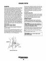
Raw Water Pump
The raw water pump is a self-priming, rotary pump with a
non-ferrous housing and a neoprene impeller. The impeller
has flexible vanes which wipe against a curved cam plate
within the impeller housing, producing the pumping action.
On no account should this pump be run dry as water acts as a
lubricant for the impeller. There should always be a spare
impeller and impeller cover gasket (an impeller kit) aboard.
Raw water pump impeller failures occur when lubricant (raw
water) is not present during engine operation. Such failures
are not warrantable, and operators are cautioned to make sure
raw water flow is present at start-up.
THERMOSTAT
A thermostat, located near the manifold at the front of the
engine, controls the coolant temperature as the coolant continuously flows through the closed cooling circuit When the
engine is first started, the closed thermostat prevents coolant
from flowing (some coolant is by-passed through a hole in the
thermostat to prevent the exhaust manifold from overheating).
As the engine warms up, the thermostat gradually opens. The
thermostat is accessible and can be checked, cleaned, or
replaced easily. Carry a spare thermostat and gasket.
NOTE: Should a failure occur with the pump s internal parts
(seals and bearings), it may be more cost efficient to purchase a new pump and rebuild the original pump as a spare.
Engines & Generators
15
COOLING SYSTEM
NOTE: Also follow the above procedure after having run hard
aground.
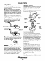
CHANGING THE RAW WATER PUMP IMPELLER
Close the raw water intake valve. Remove the pump cover
and gasket or a-ring with the aid of two screwdrivers or
pliers. Carefully pry/pull the impeller out of the pump.
Lightly coat the inside of the pump housing with glycerine.
Install the new impeller and cover with gasket, Open the raw
water intake valve.
If the engine temperature gauge ever shows a higher than
normal reading, the cause may be that silt, leaves or grass
may have been caught up in the strainer, slowing the flow of
raw water through the cooling system.
~
WASHER~
RAW WATER PUMP
INSPECTION: CHECK THE BASE OF
EACH BLADE BY BENDING VIGOROUSLY.
REPLACE THE IMPELLER IF THERE ARE
ANY CRACKS.
RAW WATER STRAINER
-STRAINER
FILTER
LIGHTLY GREASE THE PUMP
CHAMBER WITH GLYCERINEL
TYPICAL RAW WATER INTAKE STRAINER
(OWNER INSTALLED)
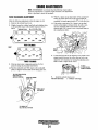
HEAT EXCHANGER
The heat exchanger is a copper cylinder which encloses a
number of small copper tubes. Raw water is pumped through
the small copper tubes and the fresh water coolant from the
engine is circulated around the copper tubes. The raw water
removes heat from the fresh water coolant.
A
CAUTION: If any of the vanes have broken off the
impeller, they must be found to prevent blockage in the
cooling circuit. They often can be found In the heat
exchanger.
Raw Water Intake Strainer
NOTE: Always install the strainer at or below the waterline so
the strainer will always be self-priming.
A clean raw water intake strainer is a vital component of the
engine's cooling system. Include a visual inspection of this
strainer when making your periodic engine check. 'The water
in the glass should be clear.
Perform the following maintenance after every 100 hours of
operation:
1. Close the raw water seacock.
2. Remove and clean the strainer filter.
3. Clean the glass.
4. Replace the washer if necessary.
5. Reassemble and install the strainer.
PETCOCK·
CLEAN
DEBRIS
CiEIWCUT
DEBRIS AT
BOTHfNDS
ZINC
ANODE
HEA T ExCHANGERS ARE
ALSO AVAILABLE WITH
CIJPRO-NiCKEL TUBfNQ
6. Open the seacock.
7. Run the engine and check for leaks.
Engines & Generators
16
COOLING SYSTEM
Zinc Anode
A zinc anode, or pencil, is located in the raw water cooling
circuit within the heat exchanger. The purpose of having the
zinc anode is to sacrifice them to electrolysis action taking
place in the raw water cooling circuit, thereby reducing the
effects of electrolysis on other components of the system.
The condition of the zinc anode should be checked monthly
and the anode cleaned or replaced as required. Spare anodes
should be carried on board.
If the zinc anodes need replacement. hold the hex boss into
.. which the zinc anode is threaded with a wrench while loos~
ening the anode with another wrench. This prevents the hex
boss from possibly tearing off the exchanger shell. After
removing the zinc, note the condition of it. If the zinc is in
poor condition, there are probably a lot of zinc flakes within
the exchanger. Remove the end of the heat exchanger and
clean the inside of all zinc debris. Always have a spare heat
exchanger end gasket in case the present one becomes damaged when removing the end cover. Replace the gasket (refer
to your engine model's heat exchanger end gasket part number), O-ring and cover, and install a new zinc anode.
NOTE: The threads of the zinc anodes are pipe threads aJ1.d
do .not require sealant. SealaJ7.t should not be used as it may
insulate the zinc from the metal of the heat exchanger housing preventing electrolysis action on the zinc.
Heat Exchanger Service
NEW
REPLACE
REPLACE
After approximately 1000 hours of operation, remove,clean
and pressure test the engine's heat exchanger. (Alocal automotive radiator shop should be able to clean and test the heat
exchanger.)
CLEAN AND
REUSE
ZINC ANODES
NOTE: Operating in silty and/or tropical waters may require
that a heat exchanger cleaning be peiformed more often than
every 1000- hours.
NOTE: Electrolysis action is the result of each particular
installation and vessel location; not that of the engine.
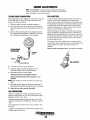
DESCRIPTION
AIR INTAKE I SILENCER
NOTE: Regular inlet filter cartridge maintenance is essentail
for proper engine operation. Failure to maintain the inlet filter
carfridge will result in air obstruction into the engine, causing
poor fuel combustion and resulting in smokey/sooty exhaust
disctu:tge ~lone ~ith lube oil comsumption and possible filter
detenoratlOn whlch could result in internal (!ngine damage.
A marine diesel engine running at 1800 rpm will typically
consume as much as 6,000 cubic feet of air per hour. Not
only must the engine room be well ventilated, the air flow
into the engine must be unrestricted.
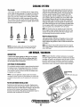
AIR INTAKE FILTER/SILENCER
The replaceable canister contains a paper element that should
be inspected every 100 operating hours. Dirt in the elemenf
~an be shaken off or cleaned with compressed air, however,
If the element is greasy or black with dirt, the canister must
be replaced, carry a spare.
FILTER CARTRIDGE
#03970
NOTE: To operate efficiently a diesel engine must intake a
continuous volwne of clear air. Hard starting, an erratic idle,
and black exhaust smoke are all symptoms of a restricted air
intake.
TURN OVER WHEN INSTALLfNG
FILTER CARTRIDGE INSTALLATION
Detach the air inlet hose from the air intake. Unplug the air
temperature sensor from the engine harness. Then remove the '
bolts that secure the air intake silencer housing to the inlet base
and remove the housing, screen facing out. Reinstall the
housing to the inlet base. Plug in the air temperature sensor to
the harness and reconnect the air inlet hose.
Engines' & Generators
17
FUEL SYSTEM
DIESEL FUEL
FUEL FILTERS
Use No.2 diesel fuel with a cetane rating of 45 or higher. Do
not use kerosene or home heating fuel.
The fuel injection pump and the fuel injectors are precisely
manufactured and they must receive clean diesel fuel, free
from water and dirt. To ensure this flow of clean fuel, the fuel
must pass through at least two fuel filters, a fuel filter/water
separator and the engine's spin-on fuel filter. Visually inspect,
clean, and change these filters according to the maintenance
schedule in this manual.
FUEL WATER SEPARATOR
A primary fuel filter of the water separating type must be
installed between the fuel tank and the engine to remove
water and other contaminant's from the fuel before they can
be carried to the fuel system on the engine.
Most installers include a filter/water separator with the
installation package as they are aware of the problems that
contaminant's in the fuel can cause.
A typical fuel filter/water separator is illustrated below.This
is the Raycor Model 500 MA. Keep in mind that if a water
separator type filter is not installed between the fuel supply
tank and engine-mounted fuel system, any water in the fuel
will affect the fuel pump, engine filter, and injection equipment. The owner/operator is responsible for making certain
the fuel reaching the engine's injection equipment is free of
impurities. This process is accomplished by installing and
maintaining a proper filtration/separation system.
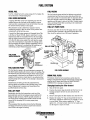
FUEL LIFT PUMP FILTER
To ensure clean fuel into the fuel lift pump, there is a small
in-line fuel filter connected to the fuel lift pump elbow. This
filter should be replaced every 200 hours of operation.
/ {\i i'
FUEL FILTER
WATER SEPERATOR
FUEL INJECTION PUMP
FUEL FILTER ASSEMBLY
The fuel injection pump is the most important component of
the diesel engine,requiring the utmost caution in handling. The
fuel injection pump has been thoroughly bench-tested and the
owner-operator is cautioned not to attempt to service it. If it
requires servicing, remove it and take it to an authorized fuel
injection pump service facility. Do not attempt to disassemble
and repair it.
Speed (hertz) and timing are the only adjustments the
servicing dealer can perform on the injection pump. Other
types of adjustments or repairs must be performed by a
qualified injection service shop.
ENGINE FUEL FILTER
Periodically check the fuel connections and the bowl for
leakage. Clean the filter element with kerosene or diesel fuel
after the first 50 hours then follow the MAINTENANCE
SCHEDULE for cleaning and replacement.
Changing/cleaning the filter element
1. Shut off the fuel supply.
2. Unscrew the retainer ring that holds the filter bowl to the
housing and allow the bowl to come away from the
housing,
3. Remove and replace the filter element and clean the bowl.
4. Replace the sealing "0" ring and reassemble the bowl to
the housing. Thread the retainer ring on carefully so as not
to cross thread. When retainer contacts the "0" ring,
tighten 114 - 112 turns by hand. Open the fuel supply and
run the engine to inspect for leaks.
FUEL LIFT PUMP
Periodically check the fuel connections to and out of the
pump and make sure that no leakage is present and that the
fittings are tight and secure. The DC ground connection at
one of the pumps mounting bolts should be clean and well
secured by the mounting bolt to ensure proper pump
operations.
When energized thru the preheat circuit, the fuel lift pump
will purge air from the fuel system and provide continuous
flow of fuel as the engine is running.
Engines & Generators
18
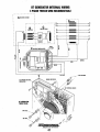
ENGINE LUBRICATING OIL
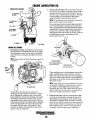
LUBRICATION DIAGRAM
2. Replacing the Oil Filter. When removing the used oil filter, you may find it helpful and cleaner to punch a hole in
the upper and lower portion of the old filter to drain the
oil from it into a container before removing it. This helps
to lessen spillage. A small automotive filter wrench
should be helpful in removing the old oil filter.
NOTE: Do not punch this hole without first loosening the
filter to make certain it can be removed.
Place some paper towels and a plastic bag around the filter when unscrewing it to catch any oil left in the filter.
(Oil or any other fluid on the engine reduces the engine's
cooling ability. Keep your engine clean.) Inspect the old
oil filter as it is removed to make sure that the rubber
sealing gasket comes off with the old oil filter. If this rubber sealing gasket remains sealed against the filter
bracket, gently remove it. :
OIL
PRES:SURE'.---'~~;
OIL
RELIEF VALVE
OIL
OIL SCREEN
ENG'INE OIL CHANGE
1. Draining the Oil Sump. Discharge the used oil through
the sump drain hose (attached to the front of the engine)
while the engine is wann. Drain the used oil completely,
replace the hose in its bracket, and replace the end cap
securely.
NOTE: Thread size for the lube oil drain hose capped end
is JI4NPT.
APPLY CLEAN ENGINE OIL
WHEN INSTALLING
8MM
SPIN ON
TURN ON HAND TIGHT
11/16 INCH
SOCKET
When installing the new oil filter element, wipe the filter
gasket's sealing surface on the bracket free of oil and
apply a thin coat of clean engine oil to the rubber gasket
on the new oil filter. Screw the filter onto the threaded oil
filter nipple on the oil filter bracket, and then tighten the
filter firmly by hand.
NOTE: Generic filters are not recommended, as the material standards or diameters of important items on generic
parts might be entirely different from genuine parts.
Immediately cifter an oil filter change and oil fill, run the
engine to make sure the oil pressure is normal and that
there are no oi/leaks around the new oil filter.
Always observe the used oil as it is removed. A
yellow/gray emulsion indicates the presence of water in
the oil. Although this condition is rare, it does require
prompt attention to prevent serious damage. Call a qualified mechanic should water be present in the oil. Raw
water present in the oil can be the result of a fault in the
exhaust system attached to the engine andlor a siphoning
of raw water through the raw water cooling circuit into
the exhaust, filling the engine. This problem is often
caused by the absence of an anti-siphon valve, its poor
location or lack of maintenance.
3. Filling the Oil Sump. Add new oil through the oil filler
cap on the top of the engine or through the side oil fill.
After refilling, run the engine for a few moments while
checking the oil pressure. Make sure there is no leakage
around the new oil filter or from the oil drain system, and
stop the engine. Then check the quantity of oil with the
lube oil dipstick. Fill to, but not over the high mark on
the dipstick, should the engine require additional oiL
Engines & Generators
19
OIL PRESSURE
DESCRIPTION
TESTING OIL PRESSURE
The lubricating system is a pressure feeding system using
an oil pump. The engine oil is drawn from the oil sump by
the oil pump, which drives the oil, under pressure, through
the oil filter, oil cooler and various lubricating points in the
engine. The oil then returns to the oil sump to repeat the
continuous cycle. When the oil pressure exceeds the specified pressure, the oil pushes open the relief valve in the oil
pump and returns to the oil sump, keeping the oil pressure
within its specified range.
To test the oil pressure, remove the oil pressure sender, then
install a mechanical oil pressure gauge in it's place. After
warming up the engine, set the engine speed at 1800 rpm
and read the oil pressure gauge.
Oil Pressure 35.0 Iblin' (3.8 kg/em') or more at 1800 rpm.
Sender and SWitch Torgue
9 -13 ft-Ib (1.2 -1.8 m - kg).
-/
FROM ENGINE
BLOCK
OIL PRESSURE
The engine's oil pressure, during operation, is indicated
by the oil pressure gauge on the instrument panel. During
nonnal operation, the oil pressure will range between 40 and
60 psi (2.8 and 4.2 kglcm2).
TESTING OIL
PRESSURE
NOTE: A newly started. cold engine can have an oil pressure
reading up to 60 psi (4.2 kg/crrrJ. A warmed engine can have
an oil pressure reading as low as 35 psi (2.5 kg/cmZ). These
readings will vary depending upon the temperature of the
engine and the rpms.
Oil PRESSURE SWITCH
OIL PRESSURE SWITCH
[NORMALLY OPEN)
LOW OIL PRESSURE
The specified safe minimum oil pressure is 4.3 + 1.4 psi (0.3
+ 0.1 kglcm2). A gradual loss of oil pressure usually indicates
a worn bearings. For additional information on low oil pressure readings, see the ENGINE TROUBLESHOOTING chart.
OIL PRESSURE RELIEF VALVE
An oil pressure relief valve is located on the engine block
just below the injection pump. This valve opens at
appoximately 50 psi [343 kpaJ and maintains that pressure.
OIL GALLERY
SEA RAY SPECIFICATIONS
LOCATED JUST
UNDER THE
FUEL INJECTION
PUMP ON THE
ENGINE BLOCK
Dll PRESSURE SWITCH
[NORMALLY OPEN)
OIL PRESSURE
SENDOR
Engines & Generators
20
REMOTE OIL FILTER (OPTIONAL)
To install, simply remove the engine oil filter and thread on
WESTERBEKE'S remote oil filter kit as shown. Always
install this kit with the oil filter facing down as illustrated.
INSTALLATION
This popular accessory is used to relocate the engine's oil filter from the engine to a more convenient location such as an
engine room bulkhead.
Contact your WESTERBEKE dealer for more information.
NOTE: Refer to ENGINE OIL CHANGE in this tn£IJlualfor
instructions on removing the oil filter.
NOTE: Westerbeke is not responsible for engine failure due to
incorrect installation of the Remote Oil Filter.
A CAUTION: It Is vital to Install the 011 lines
correctly. If the 011 Rows In the reverse direction, the
by-pass valve in the filter assembly will prevent the oil
from reaching the engine causIng an internal engine
failure. If there is no 011 pressure readIng, shutdown
Immedlalety and check the hose connections
APPLY ATHIN COAT OF CLEAN OIL TO THE O-RING WHEN
INSTALLING THIS KIT. THREAD THE KIT ON, THEN HAND
TIGHTEN AN ADDITIONAL 3/4 TURN AFTER THE O-RING
CONTACTS THE BASE.
NOTE THE "IN" AND "OUT" MARKINGS
ON THE ADAPTER WHEN THE HOSES ARE
REMOVED FOR INSTALLATION SO THEY
, WILL BE RECONNECTED CORRECTLY.
THE IN CONNECTION HOSE
MUST ATIACH TO THE OUT
CONNECTION AT THE
REMOTE OIL FILTER.
THE OUT CONNECTION HOSE
MUST ATIACH TO THE IN
CONNECTION AT THE
REMOTE Oil FIlTER.
/
APPLY ATHIN COAT OF CLEAN OIL TO THE FlL·
TER GASKET WHEN INSTALLING. AFTER THE
FIlTER CONTACTS THE BASE, TIGHTEN IT AN
AODITIONAL 3/4 TURN.
Engines & Generators
21
DC ELECTRICAL SYSTEM
1. Start the engine.
2. After the engine has run for a few minutes, measure the
starting battery voltage at the battery terminals using a
multi meter set on DC volts.
a. If the voltage is increasing toward 14 volts, the alternator is working; omit Steps 3 through 8 and go directly
to "Checking the Service Battery" on the next page.
b. If the voltage remains around 12 volts, a problem
exists with either the alternator or the charging circuit;
continue with Steps 3 through 8.
ALTERNATOR
The charging system consists of a DC belt driven alternator
with a voltage regulator, an engine DC wiring haI)1ess, a
mounted DC circuit breaker and a battery with connecting
cables. Because of the use of integrated circuits (IC's), the
electronic voltage regulator is very compact and is mounted
internally or on the back of the alternator.
50 AMP ALTERNATOR
~
MUlTlMETER
ALTERNATOR TROUBLESHOOTING
TESTING THE STARTING
BATTERY/ALTERNATOR
(ENGINE RUNNING)
I
A WARNING: A failed alternator can become very
hot. Do not touch until the altemator has cooled down.
Use this troubleshooting section to determine if a problem
exists with the charging circuit or with the'alternator. If it is
determined that the alternator or voltage regulator is faulty,
have a qualified technician check it.
The alternator charging circuit charges the starting battery
and the service battery. An isolator with a diode, a solenoid
or a battery selector switch is usually mounted in the circuit
to isolate the batteries so the starting battery is not discharged
along with the service battery. If the alternator is charging the
starting battery but not the service battery, the problem is in
the service battery's charging circuit and not with the alternator.
Testing the Alternator
3. Turn off the engine.Jnspect all wiring and connections.
Ensure that the battery terminals and the engine ground
connections are tight and clean.
A
CAUTION: To avoid damage to the battery
charging circuit, never shut off the engine battery
switch when the engine is running!
4. If a battery selector switch is in the charging circuit,
ensure that it is on the correct setting.
5. Turn on the ignition switch, but do not start the engine.
6. Check the battery voltage. If the battery is in good condition, the reading should be 12 to 13 volts.
A CAUTION: Before starting the engine make certain
that everyone Is clear of moving parts! Keep away from
sheaves and belts during test procedures.
J..o<...--MUlTIMETER
A WARNING: When testing with a multimeter:
DC ,nd AC circuits are often mixed together in marine
applications. Always disconnect a shore power corti,
isolals DC and AC converters, and shut down the engine
before performing DC testing. No AC tests should be
made without a proper knowledge of AC circuits.
TESTING THE
ALTERNATOR VOLTAGE
(IGNITION ON - ENGINE OFF)
Engines & Generators
22
e
-= GROUND
DC ELECTRICAL SYSTEM
7. Now check the voltage between the alternator output terminal (B+) and ground. If the circuit is good, the voltage at
the alternator will be the same as the battery, or if an isolator is in the circuit the alternator voltage will be zero. If
neither of the above is true, a problem exists in the circuit
between the alternator and the battery. Check al1 the
connections look for an opening in the charging circuit.
Checking the Service Battery
Check the vo1tage of the service battery. This battery should
have a voltage between 13 and 14 volts when the engine is
running. If not, there is a problem in the service battery
charging circuit. Troubleshoot the service battery charging
circuit by checking the wiring and connections, the solenoid,
isolator, battery switch, and the battery itself.
MULTI METER (JZID
MUlTIMETER
e
G!ID
COM
TESTING THE STARTING
BATTERYIALTERNATOR
(ENGINE RUNNING)
-C=:::O-...J
ENGINE
GROUND
8. Start the engine again. Check the voltage between the
alternator output and ground.
The voltage reading for a properly operating alternator
should be between 13.5 and 14.5 volts. If your alternator
is over- or under-charging, have it repaired at a reliable
service facility.
,SERVICE BATTERY
GROUND
NOTE: Before removing the alternator for repair, use a
voltmeter to ensure that 12 volts DC excitation is present
at the EXC tenninal if the previous test showed only battery voltage at the B output tenninal.
A
TESTING THE SERVICE
BATTERY (ENGINE RUNNING)
CAUTION: To avoid damaging the alternator dIodes,
do not use high voltage tester (i.e. a megger) when
performing tests on the alternator charging circuit.
If 12 volts is not present at the EXC tenninal, trace the
a
wiring and lookfor breaks and poor connections.
12 VOLT DC CONTROL CIRCUIT
Battery Care
The engine has a 12 volt DC electrical control circuit that is
shown on the wiring diagrams that follow. Refer to these
diagrams when troubleshooting or when servicing the DC
electrical system.
Review the manufacturer's recommendations and then
establish a systematic maintenance schedule for your
engine's starting batteries and house batteries.
Monitor your voltmeter for proper charging during
engine operation.
Check the electrolyte level and specific gravity with a
hydrometer.
Use only distilled water to bring electrolytes to a proper
level.
o Make certain that battery cable connections are clean and
tight to the battery posts (and to your engine).
Keep your batteries clean and free of corrosion.
A CAUTION: To avoid damage to the battery charging
circuit, never shut off the engine battery switch while
.the engine is running. Shut off the engine battery SWitch,
however, to avoid electrical shorts when working on the
engine's electrical circuit.
o
o
BAnERY
The minimum recommended capacity of the battery used in
the engine's 12 volt DC control circuit is 600 900 Cold
Cranking Amps (CCA).
A
WARNING: Sulfuric acid in lead batteries can
cauSil severe burns on skin and damage clothing. Wear
protective gear.
Engines & Generators
23
GLOW PLUGS
Re-install the plugs in the engine and test them again. The
plug::; should get very hot (at the terminal end) within 7 to 15
seconds. If the plugs don't heat up quickly, check for a short
circuit. When reinstalling the glow plugs, use anti-seize compound on the threads.
DESCRIPTION
The glow plugs are wired through the preheat solenoid.
When PREHEAT is pressed at the control panel this solenoid
should "click" on and the glow plug should begin to get hot.
INSPECTION
A
To inspect the plug, remove the electrical terminal connections, then unscrew or unclamp each plug from the cylinder
head. Thoroughly clean each plug's tip and threads with a
soft brush and cleaning solution to remove all the carbon and
oil deposits. While'cleaning, examine the tip for wear and
bum erosion~ if it has eroded too much, replace the plug.
WARNING: Do not keep a glow plug on for more
than 30 seconds. .
Glow Plug Tightening Torque
7 ·11 ft-Ib (1.0 -1.5 m-kg)
TERMINAL
TESTING
END
An accurate way to test glow plugs is with an ohmmeter.
Touch one prod to the glow plug's wire connection, and the
other t~ the body of the glow plug, as shown. A good glow
plug WIll have a 0.4 - 0.6 ohm resistance. This method can be
used with the plug in or out of the engine. You can also use.
an ammeter to test the power drain (5 6 amps per plug),
TESTING A GLOW PLUG
WITH AN OHMMETER
A WARNING: These glow plugs will become very hot
TIP
to the touch. Be careful not to burn your fingers when
testing the plugs.
TESTING A GLOW PLUG
USING A TEST LIGHT
+
Engines & Generators
24
GENERATOR WIRING DIAGRAM
#44735
~~
-!---~
IU R
It/I
PRE HEAT
~
;;
_
BATTERY SWI TCH
.... ...
r ..J?".;:t.--·
I
all PRESSURE
SI! ICH
12-24 VDC
~~
NOTE: An on-off switch
should be Installed in this
circuit to disconnect the
starter from the battery in
an emergency and when
leaving the boat Twelve
volt engine starters
typically draw 200 to 300
amps when cranking. A
switch with a continuous
rating of 175 amps at 12
VDC will normally serve
this function, but a switch
must never be used to
"make" the starter circuit.
..
:;
.
GROOND TO
ENG 1HE
SLOCK
fUSE SA
fl.
NOTE:
I. REMOVE JUMPER WHEN COHHECTlMG A SECOND REMOTE PANEl.
I
liED
II
WRT
.If
IC
(. GftOU~D 'I" TERMINAL Of PRE HEAl SOLENOID ON 14V SYSTE" OKl!.
. . . . . . .=-~~ IB('I
r-----~
---------'--"1
1"-"-"
'15 WHY
TB1-/
f81-5
-"""......--,""" ISI-3
)4..!.!.!.-W!!.!.!l!-e IB,-2
}t...!!.!........,0rSI·10
J+=.m.-H;" mI' 5
- '-+-=-I-""-""'-f-{.o'! 181"
UNIT
SWITCH
'------""-'-·....,'''''='---015/·6
STOP
SWfTa-t
HOUR
METER
VOLT
lIt 8£0
METER
t.
Engines & Generators
25
GENERATOR WIRING SCHEMATIC
#44735
6ATHR1'
-,.--
;2-2.4VDC
GLOWPLUGS
r
I
L.c
I EMERGENcY
I STOP
I PREHEA rI
ISOLENOID!
I SWI TeH
'1 TERNATOR
KI-STARf
Kl·RUN
~r~a,~,',
__________~---r----------~3~a r8~1____~-------.----~
WATER j(MP
eXN. TEMP
SWI TCH
$W! reH
OIL PRESS.
SW TCH
fUE:.. PUMp
STOP
Isol TeH
K2·R~N
1;l4(1D2
I
RELAY
86
PREHEAT
SWI TCH
START
SWI TCH
r- "cj--+---~-!o-1:
L_J
AUX. D.P. SWITCH
Oil PRESS, SUIIER
tau
TS'"
T82-1
182-8
T51-10
WATER TEMP. GAUGE
'NO. LIGHT
Oil PRESS
GAUGE
·TYPICAl R[MOIt START/SlOP fANEl CONECTIOHS-
NOfE:
o REMOT[
CONtOUR P' hS
HOURMEHR
Engines & Generators
26
GENERATOR WIRING DIAGRAM
ALTERNATOR
I I ' V 10
-
#044927 (OPTIONAL ELECTRONIC GOVERNING)
-'lOA 24VDC
o
.....---=",-fOR [XC ,
114 BRN
II 0 ORN~~
GND
I'
AL TERNATOR
WATER TEMPERATURE
0
50A-12V DC
llllQil
'6
0
GLOW
PLUGS
OMt (lLOW f'lU(l PER CYUt/DER
o
o
B
1110 ORG
~
(jj
P
0
R
I
.-------------------------+-------+--------------------+~--~
L
IIt4 VIO
0
1j14 BRN
=
1112 y[lfREC
~/'"''''''''''
~
'1011£0
~S£['01[1
EXHAUST
TEMPERATURE
SW1TCIi~
11
El£-CHIOHIC GOVERNING
i-
PREHEAT
~
o
20A CIRCUIT
I
12-24 VDC
n.-
tf2RED
r-2'0----- ----~~e<H
:-~
O! l
BREAKER-l ?VDC
A:2
ATTERY SWiTCH
I~UIT
~
BREAKER-24 VDC
~
~
AUX. OIL PRESSURE
0
SWITCtl
-
.12 yEt/liED
M-O-To-"'----.1
PRESSURE
SENDER
t1211£!l
.,
c
.166LWIHT
;;;
#16 RED
-~
FUEL PUMP
fiflFl---t---,
I
, ~I---t---.
,
~
EMERGENCY
STOP SWITCH
414 TAN
.I~~----+----~+------+--~
414 SRtI
I
ELECTRONIC GOVERNOR
CONTROLLER
@OVERSPEED BOARD
SEE ROTE 2
I
I
8lK
:~
l t=::::~'~"~RE~D~IW!!!HT~
I--I-I--II-l-I--t-+-=~;;~,
TB2
lB3
"'N
cX ;:-=-
~~=.="="=D=-----H..J.l!J"J!"lQ,D
B'<I'"
."
••
::-;-::'8
L--_ _ _ _-jo~+-
TBt
~1 :~: R::T£ \~<I-+-+--+--'
-~':"
TRANSIERT
VOLTAGE
SUPPRESSOR
f:ED
;
4114 V!O
.14 VIO
!;:-~
'---------iFi.Sf"--+--+--i-+--'-"'-'-'''--,
~
::-;:_
~il.
I-
.14.AT:;
,.
...,.
~:F-~~.,:r==F-+--1i-t-J
I'-----------+O~
~. •
:'c;rf---
6lN
~~
L________l=::::~'~1_+~~t_+2~~K2:::t~=~·:':·.:'~K!7;t!=~=:t==--t-----.!!..U~
L-----=-"WH-"'~~{\
t!4Rt::
t!4SU
.16 eRN
VI.
VI.
~
.14 'HI
~
414 ..lIT
-"'-
tl6YH
t!6 RED
1160RG
*16 WHT
tIS II".
J-J
SPEED
ACTUATOR
(a
ROTE:
~
(j
l
Imi
1 REMOVE JUMPER WHEN CONNECTING A SECOND REIIOTE PAon
2, GROUND "'" TERMIN" or PRlHlH SOLENOIO ON 2'V SYSTEM ONLY
tI6ftE~"HT
.IS
T82-1
tI6t1EO/WltT
~,,,R<;,-
_ _ _ _-,
OIL
'(B2-2
TBI-S
PREHEAT
PRESSURE
SWITCH
o
TBI-3
TBI-2
~
TBI-IO
:;:
~
START
SWITCH
-
TB2-5
TB2"4
STOP
SWITCH
L -_ _ _-''-'-''''''''''-_--\~
TB2-B
VOLT
HOUR
L METER
METER
Engines & Generators
27
'16 REP
INSTRUMENT
PANEL
rUSE BA
-
I
GENERATOR WIRING SCHEMATIC
#044927 (OPTIONAL ELECTRONIC GOVERNING)
+.
r .., BATTERY
I
C I R(;U I T
BREAKER
r - - -__~r~~~
l_J
I
SWITC~
STARiER
____--------O_--~~~--~
GI.OWPlUGS
r .., EMERGENCY
~~
I PREH[AT I
STOP
ISOl['O'~
SWlfCH
AL TER~ATOR
B
fill-START
1(2-RUIt
~,~.~,.~,----------~--~----------~3oy' ~.1~
£XIL lENf'.
5Wf1CH
8A
,-,rhsrop
wAT£lr T£kP.
SWITCH
I i""ISWITCH
__________-,____-4
Oil PRESS.
SWITCH
Kl-AUtl A[UT
IM4l)O,
......
t------------t*---------~~_i--------~.!cj.
PR(~EAT
STAAT
SWITCH
sWITCH
KI-SiART RELAY
r -;,
r -.•l~-+-____-+__________________.£!••C(
[
L_J
.J
85
85
A.uX. O.P. SWitCH
OIL PII£.$$, SUO!R
T81-]
RI-4
lBl-l
181-S
lei-If)
WATER
'-
TE~P.
GAUGE
.....
STOP
SWITCH
PREHEAT
sWnCH
r-
STARr
SWITCH
IND:. LIGHT
;,.o:-_~....;r~-. ~l_
l_...J
OIL PRESS. GAuGE
L_J
-TYPICAL REMOTE START/STOP PAItH COM£CTlOHS'
.01[:
o mOlE '''''£<lOR PIHS
HOURMETER
Engines & Generators
28
REMOTE INSTRUMENT PANEL
#44329
STOP SW ITCH
...
I
'2
5
PREHHf
SW I TeH
REMOTE CONTROL PANEL (REAR VIEW)
"-"-"-"-"-"-"-"-"-"
START SWITCH
o
STOP
SW ITCH
.JII6 REDfVl
#16 BlK
# 16 RED/VIm
~16
WHT
Q)CDc)
110 RED
.1
0
@@®
@G@
PREHEAT
SWITCH
START
SWITCH
#16 WHT/RED
1
MALE CABLE
CONNECTOR
REAR VIEW
#14 REO
# 14 RED
I
#16 YELIRED
P. N.
EXTENSION WIRING IS AVAILABLE
FROM YOUR WESTERBEKE DEALER
44336
15 FT EXTENSION - #044347
30 FT EXTENSION - #044799
CONNECTOR FOR TWO
FyF
REMOTE PANELS - #046116
M
Engines & Generators
29
ENGINE TROUBLESHOOTING
Note: The engine's electrical system is protected by a 20 amp
manual reset circuit breaker located on a bracket at the rear
of the engine.
The following troubleshooting table describes certain
problems relating to engine service, the probable causes of
these problems, and the recommendations to overcome
these problems.
Problem
Key switch on, PREHEAT switch
depressed: no panel indications;
fuel solenoid or electrical fuel pump
START SWITCH DEPRESSED. no starter
engagement
Verifi&atioD/Remedy
Probable Cause
1. Batlery Switch not on,
1. Check switch and/or battery connections.
2. Emergency stop switch off.
2. Check emergency stop switch position.
3. 20-Amp circuit breaker tripped.
3. Reset breaker; II breaker trips again, check preheat solenoid circuit
and check circuit for shorts to ground.
4. 10-Amp breaker tripped on
preheat solenoid.
4. Check voltage at and atter breaker on preheat solenoid.
5. Loose battery connections.
5. Check (t) connection to starter solenoid and (-) connection to engine
ground stud, Check battery cable connections,
6. Preheat solenoid not operating.
6. Check solenoid "S" terminal for voltage.
1. Connection to solenoid faulty,
1. Check connection,
2. Faulty switch,
2. Check switch witll ohmmeter.
3. Faulty SOlenoid.
3. Check that 12 volls are present at the solenoid connection.
5. Loose battery connection.
5. Check battery connections.
6. Low battery.
6.
START switch is depressed; panel
indications OK; starter solenoid OK
fuel solenoid not functioning.
1. Poor connections to fuel solenoid,
1. Check connections,
2. Defective fuel solenoid.
2. Check that 12 volts are present atthe (t) connection on the fuel nun
solenoid,
Generator engine cranks. but does not
start, fuel solenoid energized.
1. FauHy fueling system.
1. Clleck that fuel valves are open.
C~eck
battery charge state.
1a. Switch to combine house and start batteries.
1b. Replace batteries,
1c. Check fuel lift pump,
2. Preheat SOlenoid faulty,
2. Check solenoid,
3. Low battery,
3. Switch to combine batteries.
Engine can~ be stopped,
1. Faulty DC alternator.
1. Remove Exc. connection at alternator, repair alternator.
Battery runs down.
1. Oil Pressure switch.
1. Observe if gauges and panel lights are activated when engine is not
running. Test the oil pressure switch.
2. High resistance leak to ground.
2. Check wiring. Insert sensitive (0 - .25 amp) meter in battery lines, (Do
34'1. Replace batteries.
not start engine,) Remove connections and replace after short is
located.
3. low resistance leak.
3. Check all wires for temperature rise to locate the fault
4. Poor battery conditions.
4. Check cable connections at battery for loose connections, corrosion.
5. DC alternator not charging,
5. Check connections, check belt tenSion, test alternator.
1. DC charge circutt faulty,
1. Perform DC voHage check of generator changing circuit. See
TES[ING THE BATTERY CHARGING CIRCUITin this manual.
2. Alternator drive.
2. Check drive belt tension, Alternator should turn freely. Check for loose
See DC ELECTRICAL SYSTEM/ALTERNATOR.
Battery not changing
connections. Check output with voltmeter, Ensure 12 volts are present
at the Exc, terminal.
Generator engine stops
1. Fuelli1t pump failure.
1. Fuellitt pump should make a distinct licking sound. Replace pump.
1a. In-Une filter is clogged.
1a. Replace filter,
2. Switches and/or wiring loose or disconnected,
2. Inspect wiring for short circuits and loose connections. Inspect
3. Fuel starvation,
3. Check fuel supply, fuel valves, fuel lift pump.
4. 20 Amp circuit breaker tripping.
4. Check for high DC amperage draw during operation, Ensure breaker is
not overly sensitive to heat which would cause tripping,
5. Exhaust system is restricted,
5. Check for blockage, collapsed hose, carbon buildup at exhaust elbow,
6. Water in fuel.
6. Pump water from fuel tank(s), change filters and bleed fuel system.
7. Air intake obstruction.
7. Check air intake finer cartridge.
switches for proper operation.
Engines & Generators
30
ENGINE TROUBLESHOOTING
Problem
Generator engine overheats/shuts down.
Generator engine sh!Jts down,
Low oil pressure.
Probable Cause
Verification/Remedy
1. Raw water not circulating.
2. Coolant not circulating.
1. Raw water pump failure. Check impeller - replace.
2. Obstruction at raw water intake or raw water filter.
2a. Thermostat - remove and test in hot water.
Replace thermostat.
2b. Loss of coolant - check hoses, hose clamps, drain plug, etc.
for leaks.
2c. Broken or loose belts - tighten/replace.
2d. Air leak in system; run engine and open the pressure cap to
bleed air. Add coolant as needed.
1. Check dipstick, look for oil leaks at oil filter and at
oil drain hose connection.
1. Loss of oil.
1. Exhaust too hot.
2. Replace oil pressure switch.
1. Check raw water injection flow, look for exhaust obstruction.
2. High temperature switch opens at .
too Iowa temperature.
2. Check for satisfactory operation with switch bypassed,
check with ohmmeter, replace if faulty.
1. Blue smoke.
1. Incorrect grade of engine oil.
1a. Crankcase is overfilled with engine oil (oil is blowing out
2. White smoke.
2. Engine is running cold.
2a. Faulty injector or incorrect injector timing.
3. Improper grade of fuel.
3a. Fuel bum incomplete due to high back pressure in exhaust or
insufficient air for proper combustion (Check for restrictions in
exhaust system; check air intake.).
2. Oil pressure switch.
Generator engine shuts down,
High exhaust temperature.
Exhaust smoking problems
through the exhaust).
3. Black smoke.
3b. Improperly timed injectors or valves or poor compression.
3c. Lack of air - check air intake and air filter. Check for proper
ventilation.
3d. Overload.
Engine alarm sound pulsates
1. Loss of oil.
1. Check dipstick, look for oil leaks at oil filter and at oil drain
hose connection.
2. Replace oil pressure switch.
2. Oil pressure switch.
Engine alarm sounds continuously
1. Engine Coolant.
2. High temperature switch opens at
too Iowa temperature.
1. Check engine coolant level.
2. Check for satisfactory operation with switch by-passed,
check with ohmmeter, replace if faulty.
Engines & Generators
31
CONTROL PANEL TROUBLESHOOTING
MANUAL STARTER DISCONNECT (TOGGLE SWITCHES)
NOTE: The engine control system is protected by a 20 amp manual reset circuit breaker
located on the engine as close as possible to the power source.
Problem
Verification/Remedy
Probable Cause
PREHEAT depressed, no panel indications
fuel solenoid, electric fuel pump and
preheat solenoid not energized.
1. Oil Pressure switch.
1. Check switches and/or battery connections.
2. 20 amp circuit breaker tripped.
2. Reset breaker. If opens again, check preheat solenoid circuit
and run circuit for shorts to ground.
START SWITCH DEPRESSED. no starter
engagement.
1. Connection to solenoid faulty.
1. Check connection.
NO IGNITION. cranks. does not start.
NOT CHARGING BATTERY
2. Faulty switch
2. Check switch with ohmmeter.
3. Faulty solenoid.
3. Check that 12 volts are present at the solenoid connection.
4. Loose battery connections.
4. Check battery connections.
5. Low battery.
5. Check battery charge state.
1. Faulty fueling system.
1. Check for fuel.
2. Check for air in the fuel system.
2. Allow system to bleed.
3. Faulty fuel lift pump.
3. Replace fuel lift pump.
1. Faulty alternator drive.
1. Check the drive belt and its tension. Be sure the alternator
turns freely. Check for loose connections. Check the
output with a voltmeter. Ensure 12V are present at the
regulator tenminal.
BATTERY RUNS DOWN
1. Oil pressure SWitch.
1. Observe If the gauges and panel lights are activated when the
2. High resistance leak to grou nd.
2. Check the wiring. Insert sensitive (0-.25 amp) meter in battery
lines (Do NOT start engine). Remove connections and replace
after short is located.
3. Low resistance leak to ground.
3. Check all wires for temperature rise to locate the fault.
4. Faulty alternator.
4. After a good battery charging. disconnect alternator at output.
If leakage stops. Remove alternator and bench test. Repair or
replace.
engine is not running. Test the oil pressure switch.
TROUBLESHOOTING WATER TEMPERATURE AND OIL PRESSURE GAUGES
If the gauge reading is other than what is normally indicated
by the gauge when the instrument panel is energized, the first
step is to check for 12 volts DC between the ignition (B+)
and the Negative (B-) terminals of the gauge.
Assuming that there is 12 volts as required, leave the instrument panel energized (key switch on) and perform the
following steps:
1. Disconnect the sender wire at the gauge and see if the
gauge reads zero, which is the normal reading for this situation.
2. Connect the sender terminal at the gauge to ground and
sec if the gauge reads full scale, which is the normal reading
for this situation.
If both of the above gauge tests are positive, the gauge is
undoubtedly OK and the problem lies either with the conductor from the sender to the gauge or with the sender.
If either of the above gauge tests are negative, the gauge is
probably defective and should be replaced.
Assuming the gauge is OK, check the conductor from the
sender to the sender terminal at the gauge for continuity.
Check that the efIgine block is connected to the ground.
Some starters have isolated ground terminals and if the battery is connected to the starter (both plus and minus terminals), the ground side will not necessarily be connected to the
block.
Engines & Generatots
32
.
ENGINE ADJUSTMENTS
DRIVE BELT ADJUSTMENT
ELECTRONIC GOVERNOR (OPTIONAL)
Proper inspection, service and maintenance of the drive belts
is important for the efficient operation of your engine (see
Drive Belts under MAINTENANCE SCHEDULE).
Drive belts must be properly tensioned. Loose drive belts will
not provide proper alternator charging and will eventually
damage the alternator. Drive belts that are too tight will pull
the alternator out of alignment and/or cause the alternator to
wear out prematurely. Excessive drive belt tension can also
cause rapid wear of the belt and reduce the service life of the
fresh water pumps bearing. A slack belt or the presence of oil
on the belt can cause belt slipping, resulting in high operating
temperatures.
The drive belt is properly adjusted if the belt can be deflected
no less than 3/8 inch (lOmm) and no more than 112 inch
(12mm) as the belt is depressed with the thumb at the midpoint between the two pulleys on the longest span of the belt.
A spare belt or belts should always be carried on board.
The Electronic Governor regulates the engine speed by
sensing the engine's RPM with a magnetic pick-up at the
flywheel. The governor's controller continuously monitors
the engines speed and if there is any discrepancy, the
controller signals the actuator and the actuator adjusts the
engine to the desired speed electronically.
A
WARNING: Never attempt to check or adjust the
drive belt's tension while the engine is in operation.
Actuator
The following instructions are for adjusting or replacing
the actuator.
Adjusting Belt Tension
1. Shut-off the DC power to the g~nerator.
2. Disconnect the actuator wires from the wiring harness.
3. Measure the distance between the actuator and the engine
mounting surface as shown.
1. Loosen the alternator adjusting strap bolt and the base
2.
3.
4.
S.
mounting bolt.
With the belt loose, inspect for wear, cracks and frayed
edges.
Pivot the alternator on the base mounting bolt to the left
or right as required, to loosen or tighten.
Tighten the base mounting bolt and the adjusting strap
bolt.
Run the engine for about 5 minutes, then shut down and
recheck the belt tensions.
ACTUATOR
'JAM NUT
MEASURE FOR
REFERENCE ..
ENGINE SPEED/ENGINE SHUTDOWN
4. Back-off the 1 7/16" jam nut and unscrew the actuator.
5. Apply a small amount of teflon sealant to the replacement
actuator and screw the actuator into the engine's
mounting boss. Maintain the same distance between the
actuator and the engine mounting surface as previously
measured Secure the actuator's position with the jam nut.
(The standard distance is 13/16" to 7/8").
6. Reconnect the actuator wires and test the unit.
Generator frequency (hertz) is a direct result of engine speed.
The engine speed throttle adjusting screws have been pre-set
at the factory.
A fuel shut off solenoid, located at the injection pump, shuts
the generator down when the control panel toggle switch is
depressed. This solenoid is pre-set at the factory.
.~
ENGINE MOUNTING
SURFACE
~~
SCREWINTO .
ORIGINAL MEASURE
SPEED ADJUSTMENT
[FACTORY SET]
J
FUEL SHUT OFF SOLENOID
Note: If the unit does not shut down properly when
. testing. Loosen the jam nut and turn the
actuator in lIS-lf4 of a turn until proper shut
dmvn is achieved.
Engines & Generators
33
13/16" TO 7/8"
STANDARD
ENGINE ADJUSTMENTS
NOTE: WESTERBEKE recommends that the following engine adjustments be performed by a competent engine mechanic. The information
below is provided to assist the mechanic.
VALVE CLEARANCE ADJUSTMENT
(b) With No.1 piston at top dead center on the compression
stroke, the rocker arms will not be moved when the
crankshaft is turned approximately 200 in both directions.
Make the following adjustments when the engine is cold.
1. Remove the cylinder head cover.
(c) If the rocker arms move, No.1 piston is at top dead
center on the intake or exhaust stroke. In such a case,
tum the crankshaft 3600 in the direction of engine
rotation again. No.1 piston is now at top dead center on
the compression stroke.
2. Slightly loosen the cylinder head bolts and retighten them
to the specified torque in the number sequence shown
below.
Tightening Torque
65:t4Ib-ft (88£5 Nm)
02
05
011
FRONT
FOUR CYLINDER
4. Loosen the lock nut for the adjusting screw. With a feeler
gauge inserted between the rocker arm and valve cap,
adjust the valve clearance by turning the adjusting screw.
Make certain to adjust all the valves.
THREE CYLINDER
3. Find top dead center compression position for No.1
piston by using the procedure that follows:
(a) Tum the crankshaft until IDe mark on the crankshaft
puUey is aligned with the mark on the timing gear case.
i
• ':
I
~
TDC (TOP DEAD CENTER)
MARK FOR NO.1
AND NO.4 PISTONS
5.
i
",,,.
.<1:
,if
'~.~~
:t
-
--
~
rr
O.25mm
{O.0098 INCHES)
INTAKE & EXHAUST
~
Install the cylinder head cover.
Head Cover Bolt Torque
TIMING GEAR
CASE MARK
TDC MARK FOR
NO.2 AND NO.3 PISTONS
Engines & Generators
34
'~
2 - 3 It-Ib (0.3 - 0.45 m-ku)
ENGINE ADJUSTMENTS
NOTE: WESTERBEKE recommends that the following engine adjustments be peiformed by a competent engine mechanic. The tnformation
below is provided to assist the mechanic.
TESTING ENGINE COMPRESSION
FUEL INJECTORS
Make certain the oil level (dipstick) is at the correct level and
the air intake filter is clean. The battery and starter motor
must also be in good condition.
1. Warm the engine to normal operating temperature.
2. Move the control lever to a position for shutting off the
fuel. (Disconnect the wires if a fuel shutdown solenoid is
used).
3. Remove all the glow plugs from the engine and install
the compression gauge/adapter combination to the cylinder on which the compression is to be measured.
In case of severe vibrations and detonation noise, have the
injectors checked and overhauled by an authorized fuel
injection service center. Poor fuel quality, contaminants and
loss of positive fuel pressure to the injection pump can result
in injector faults. Since fuel injectors must be serviced in a
clean room enviroment, it is best to carry at least one extra
injector as a spare should a problem occur.
Before removing the old injector, clean the area around the
base of the injector to help prevent any rust or debris from
falling down into the injector hole. If the injector will not lift
out easily and is held in by carbon build-up or the like, work
the injector side-to-side with the aid of the socket wrench to
free it, and then lift it out.
The injector seats in the cylinder head on a copper sealing
washer. This washer should be removed with the injector and
replaced with a new washer when the new injector is
installed.
TESTING ENGINE
COMPRESSION
Injector to Cylinder Head Tightening Torqlle 40 ± 4 fHb (5.5 ± 0.5 kgf-m)
PRESSURE
GAUGE
ADAPTER
~WPLUGHOlf
FUEL INJECTOR I
I
4. Close the raw water seacock (thru-hull).
5. Crank the engine and allow the gauge to reach a
maximum reading, then record that reading.
6. Repeat this process for each cylinder.
Compression pressure 427 psi (30 kgffcm2) at 290 rpm.
Maximum permissible difference between cylinders is 42.7 psi
(3 kgf/cm2)
NOTE: If the readings are below the limit, the engine needs
repair
7. Re-install the glow plugs (use anti-seize compound on
the threads) and reset the fuel shut-off to the run position.
S. Open the raw water seacock (thru-hull).
LOW COMPRESSION
When low compression is found, determine the cause by
applying a small amount of oil in the cylinder thru the glow
plug hole. Allow the oil to settle.
Install the pressure gauge and repeat the above test. If the
compression reading rises dramatically, the fault is with the
rings.
If the compression valve does not rise, the problem is with
the valves.
A slight rise in compression would indicate a problem with
both the rings and the valves.
Engines & Generators
35
GENERATOR INFORMATION
USE OF ELECTRIC MOTORS
GENERATOR FREQUENCY ADJUSTMENT
The power required to start an electric motor is considerably
more than is required to keep it running after it is started.
Some motors require much more current to start them than
others. Split-phase (AC) motors require more current to start,
under similar circumstances, than other types. They are
commonly used on easy-starting loads, such as washing
machines, or where loads are applied after the motor is
started, such as small power tools. Because they require 5 to
7 times as much current to start as to run, their use should be
avoided, whenever possible, if the electric motor is to be driven by a small generator. Capacitor and repulsion-induction
motors require from 2 to 4 times as much current to start as
to run. Thc current required to start any motor varies with the
load connected to it. An electric motor connected to an air
compressor, for example, will require more current than a
motor to which no load is connected.
Frequency is a direct result of engine/generator speed, as
indicated by the following:
• When the generator is run at 1800 rpm, the AC voltage
output frequency is 60 Hertz.
• When the generator is run at 1500 rpm, the AC voltage
output frequency is 50 Hertz.
Therefore, to change the generator's frequency, the generator's drive engine's speed must be changed along with a
reconfiguring of the AC output connections at the generator.
GENERATOR MAINTENANCE
• Maintaining reasonable cleanliness is important.
Connections of tenninal boards and rectifiers may become
corroded, and insulation surfaces may start conducting if
salts, dust, engine exhaust, carbon, etc. are allowed to
build up. Clogged ventilation openings may cause excessive heating and reduced life of windings.
In general, the current required to start 115-Volt motors connected to medium starting loads will be approximately as
follows:
MOTOR SIZE
(HP)
AMPS FOR
RUNNING
(AMPERES
AMPS FOR
STARTING
(AMPERES)
1/6
1/4
3.2
4.6
6.4 to 22.4*
• For unusually severe conditions, thin rust-inhibiting
petroleum-base coatings should be sprayed or brushed
over all surfaces to reduce rusting and corrosion.
1_ _ _ _······_ _--+____
10_.2_... _ _+---=:.:..:...:~:.::......._
13
• In addition to periodic cleaning, the generator should be
inspected for tightness of all connections, evidence of
overheated terminals and loose or damaged wires.
__l
26 to 52
• The drive discs on single bearing generators should be
checked periodically if possible for tightness of screws
and for any evidence of incipient cracking failure. Discs
should not be allowed to become rusty because rust may
accelerate cracking. The bolts which fasten the drive disc
to the generator shaft must be hardened steel SAE grade
8, identified by 6 radial marks, one at each of the 6 corners of the head.
*NOTE: In the above table the maximum Amps for Starting is
more for some small motors than for larger ones. The reason
for this is that the hardest starting types (split-phase) are not
made in larger sizes.
Because the heavy surge of current needed for starting
motors is required for only an instant, the generator will not
be damaged if it can bring the motor up to speed in a few
seconds. If difficulty is experienced in starting motors, turn
off all other electrical loads and', if possible, reduce the load
on the electric motor.
• The rear armature bearing is lubricated and sealed; no
maintenance is required. However, if the bearing becomes
noisy or rough-sounding, have it replaced.
• Examine bearing at periodic intervals. No side movement
of shaft should be detected when force is applied. If side
motion is detectable, inspect the bearing and shaft for
wear. Repair must be made quickly or major components
will rub and cause major damage to generator.
REQUIRED OPERATING SPEED
Run the generator first with no load applied, then at half the
generator's capacity, and finally loaded to its full capacity as
indicted on the generator's data plate. The output voltage
should be checked periodically to ensure proper operation of
the generating plant and the appliances it supplies. If an AC
voltmeter or ampmeter is not installed to monitor voltage and
load, check it with a portable meter and amprobe.
Carbon Monoxide Detector
WESTERBEKE recommends mounting a carbon
monoxide detector in the vessels living quarters. Carbon
monoxide, even in small amounts, is deadly.
NOTE: When the vessel in which the generator is installed
contains AC equipment of 120 volts only, it is recommended
that the generator's AC temzinal block be configured to provide one 120 volt AC hot leg for the vessel's distribution
panel. This will ensure good motor starting response from the
generator:
The presence of carbon monoxide indicates an exhaust
leak from the engine or generator or from the exhaust
elbow/exhaust hose, or that fumes from a nearby vessel
are entering your boat.
If carbon monoxide is present, ventilate the area with
clean air and correct the problem immediately!
Engines & Generators
36
BT GENERATOR
This generator is a four-pole, brushless, self-excited generator
which requires only the driving force of the engine to produce AC output. The copper and laminated iron in the exciter
stator are responsible for the self-exciting feature of this generator. The magnetic field produced causes an AC voltage to
be induced into the related exciter rotor windings during rotation. Diodes located in the exciter rotor rectifY this voltage to
DC and supply it to the windings of the rotating field. This
creates an electromagnetic field which rotates through the
windings of the main stator, inducing an AC voltage which is
supplied to a load. A step down transformer is connected in
parallel to the AC output of the main stator. An AC voltage is
produced in the auxiliary windings of the transformer and the
main stator and is, in tum, supplied to a full-wave bridge rectifier. The rectifier produces a DC voltage to further excite
the exciter stator windings, enabling the generator to produce
a rated AC output An optional solid-state voltage regulator is
available to work in tandem with the transformer regulator to
produce a more stable AC output.
A circuit breaker is installed on all WESTERBEKE generators.This circuit breaker will automatically disconnect generator power in case of an electrical overload. The circuit
breaker can be manually shut off when servicing the generator to ensure no power is coming into the boat.
NOTE: This circuit breakzr is available as a WESTE1?BEKE
add-on kit for earlier model generations; contact your
WESTERBEKE dealer.
SHIMS
.LU'If,r-U'UWU
TRANSFORMER
BT GENERATOR
SINGLE PHASE
[6 STUD]
COMPOUND
TRANSFORMER
AC TERMINAL BOARD
BRIDGE
RECTIFIER
BT GENERATOR
SINGLE PHASE
[12 STUD]
Engines & Generators
37 .
BT GENERATOR I SINGLE PHASE [SIX STUD]
r-------------------,
BOO!
:*
I
~I
A
+:
+
i,
B
II
4
_:
b
2 ~
1
:
2
I
3
~-----------------~
r----[j-----l
r----()-----1
i
I i !. . . .
I~i)
I :
il I ! i
I
:
2
I
RM1""t
11
I
I
:
I
II
:•
_ ________
.J
3'
•
•
60 Hz TERMINAL
2
'1
1
I
I
I
I
_
G
.JI
:a
".
RED
~
REO
!JED
GREEN
GREEN
BLACK
BlACK
BLACK
BLACK
+ ...-'''''-........
BLUE
~--------~~----~
~------------~~--~
BlUE
YELLOW
AVR
PLUG
REDI WHITE
(TO HIiRTZlVOLTS BAR)
!!LUE IWHrre
{TO PIN 18 TERM.
eWE {WOOE
(TO HERT2NOLTS BAlI)
VELLOW/WHrt"e
(TO SELECTOR SWITCH)
I!I.ACKIWHrrE
(TO BRIDGE RECTlFlER)
INTERNAL WIRING SCHEMATIC (SIX STUD)
W/OPTIONAL VOLTAGE REGULATOR
A. EXCITER STATOR WINDINGS 1& 2
A-I and A - 2 Exciter Stator Windings
(Selector in COMP position)
D. COMPOUND TRANS.FORMER
1. Compound Transformer Windings
2. Compound Transformer Windings
3. Compound Transformer Auxiliary Windings
Resistance readings and voltage checks can be accessed
easily for the components in the exciter circuit A, G, C-3 and
D-3 by locating the color coded wires at the connection
points shown on the above schematic. When cpecking
winding resistance values be sure to lift both of the
component's electrical connections.
G. BRIDGE RECTIFIER
A.V.R.
Optional Automatic Voltage Regulator Plug (6 Prong).
B. EXCITER ROTOR and FIELD
1. Auxiliary Windings (A - B - C)
2. Diodes (6)
3. Rotating Field Windings
4. Posi Resistor
C. MAIN STATOR
1. Main Stator Windings
2. Main Stator Windings
3. Main Stator Auxiliary Windings
Engines & Generators
38
GENERATOR VOLTAGE ADJUSTMENT
NOTE: WESTERBEKE recommends that the following generator
tests and adjustments be peiformed by a quailified technician.
Generator Frequency
d. After the no-load hertz adjustment is made, the no-load
voltage may need to be readjusted. In most cases, if the
generator was producing the correct no-load voltage at
the previous hertz setting, it would be correct at the
changed hertz setting.
In the event it needs adjustment, adjust the shim thickness under the laminated steel bar of the transfonner.
60 hertz: no-load voltage, 121-124 volts.
50 hertz: no-load voltage, 232-236 volts.
1. Frequency is a direct result of engine/generator speed:
1800 rpm =60 hertz
1500 rpm 50 hertz.
2. To change generator frequency follow the steps below.
a. Connect the AC output leads to the AC terminal block,
following the illustrations on this page.
e. Load the generator to the rated amperage output
corresponding to the hertz speed of the generator.
Rated Loaded Speed
60 hertz: loaded speed, 58.5 - 59.0 hertz
50 hertz: loaded speed, 48.5 - 49.0 hertz
The lowest acceptable voltage at full rated output
(amps)
60 hertz: 108 - 11 0 volts
50 hertz: 205 - 210 volts
h. If an AVR is installed, reposition the blue or blue/white
lead to correspond to the hertz selected on the
Voltage!Hertz Connection Bar.
If there is no antomatic voltage regulator (AVR
installed, do not change the wiring on the
Voltage/Hertz Connection Bar. Simply reconfigure the
AC terminal for the hertz change.
c. Start the engine, monitor voltage and adjust engine
no-load speed. Adjust diesel units by the linkage
between the throttle arm and fuel solenoid or the
throttle lever on the injection pump..
60 hertz; no-load speed,
61.5 - 62.0 hertz.
50 hertz: no-load speed,
51.5 - 52.0 hertz.
SIX STUD AC VOLTAGE CONNECTIONS
120V 60HZ
115V50Hz
230V50Hz
® @
® @
120/240V 60HZ
A JUMPER IS III~_-.J
REQUlRED'-1gg]
•
TWELVE STUD AC VOLTAGE CONNECTIONS
The frame ground wire must
be moved when changing
from 115 volts and 1101220
volts 50 hertz to 230 volts
50 hertz. From making connections to the AC tenninal
block, use tenninal ends for
1/4 inch studs that wiD
accept multi-strand copper
wire sized for the amperage
rating from the hot lead connection. The frame ground
wire is white or white with a
green strip. It connects
between the neutral stud
and the generator frame.
115V 50Hz
230V50Hz
a:::::o
a::::::::D
0
115/230V 50Hz
a:::::o
0
120V:O Hz
o
0
6 6
I"
120/240V/60Hz
a:=:o
l2
"1
-"""",.......roN
N l1
1'!;;jb!jJCIRCUIT
l!::::i
BREAKER
L1
OJ
• •
• •
A JUMPER IS
REQUIRED
Engines & Generators
39
GENERATOR VOLTAGE ADJUSTMENT
NOTE: WESTERBEKE recornmends that the following generator
tests and adjustments be performed by a quailif{ed technician.
NO-LOAD VOLTAGE ADJUSTMENT
FULL-LOAD VOLTAGE ADJUSTMENT
Voltage adjustment is made with the generator regulation
being governed by the compound transformer.
1. The selector switch, if installed, must be in the COMP
position.
The voltage hertz connection bar that is used when changing
from 60Hz to 50Hz can also be used to increase or decrease
the generators full-load output.
Fine voltage adjustments can be performed by repositioning
wires A to leads #1, #2, and #3 increasing the loaded voltage
progressively in that order. A no-load voltage adjustment will
have to be made as well.
Should full-load output fall below 108 volts-60Hz
(210 volts-50Hz), the voltage should be adjusted.
2. To confirm no-load voltage, start the generator and apply
a momentary (moderate) load to excite the transformer.
The voltage produced by the generator after the momentary load is removed is no-load voltage. Note the voltage
output from the generators 120 volt leges) (230 volt 50
hertz). The no-load voltage should be between 121-124
volts at 61.5-62 hertz (232- 236 volts at 51.5-52 hertz).
A TWORED
WIRES
NOTE: The no-load voltage should be adjusted to the voltage
produced by the generator once started and a momentary
load should be applied to excite the transformer and then
removed. The voltage produced by the generator after this
momentary load is removed is no-load voltage.
12 STUD
3. To raise or lower the voltage, shims of varying thickness
A BLUE
(non-conductive material) are placed or removed from
under the steel laminated bar on top of the compound
transformer. The material used for shimming should not
soften at temperatures in the 1760 F (800 C) range. A
small reduction in no-load voltage (1 to 3 volts) can some
times be accomplished by gently tapping the top of the
laminated steel bar to reduce the gap between the existing
shims and the transformer core.
NOTE: No-load voltage may be effected needing readjustment
with the compound transfonner. Do not use these
adjustments to compensate for overload conditions being
placed on the generator/engine (inductive-motor type loads).
Loss of generator hertl/speed, the result of overload, will
cause a drop in voltage output.
WIRE
~~\;""~IP
6 AND 12 STUD VOLTAGE HERTZ
CONNECTION BARS
NOTE: When the optional voltage regulator is installed
and if the BluelWhite (Blue) lead is not correctly positioned
to correspond to the Hertz the unit is operating at, the
regulator will sense incorrect voltage and cause the generator
to produce abnormally high output voltage.
Shim thickness of 0.001 inch will change the no-load
voltage by approximately 4 - 6 volts. Adding shim
material raises the no-load voltage. Removing shim
material lowers no-load voltage.
Engines & Generators
40
BT GENERATOR INTERNAL WIRING
3 PHASE TWELVE WIRE RECONNECTABLE
r----I
I
--
-
---,
I
A EXCITER STATOR
I
r------
I
I
I
I
1----
r----
I
I
I
I
I
I
I
:
I
...-------,
+
I
8
EXCITER
I
I
1
:
I
..---..... I
c
: 8....-----~1~--~~1~------.'7
I
I
ROTOR FIELD
(6)
:
- - - - - -", 12".----l1f---l--...-+1----.'11
I 10.
I
I
-9
I
I
I
C
:rII-as:~1-1.p1I
DSTATOR
1
f
6-
I
I
I
I
I
-5
: 2....------LI__. . . .~I~------·1
1----.....,
I 4
I
I
I
DIODES
/--------
3
I
I
I
..J
L_
Q
w
a::
fa
...
red ....
green to...
yellow t -
GREEN
~1Iz
~
Amp
e
Slab
i
RED
BLUE
Volt
~
YElLOW
,/ ~ FUSE HOLDER
/
.
ELECTRONIC VOL
REGULATOR
TERMINAL BOARD
BT GENERATOR
THREE PHASE
20A
Enginss; & Generators
41
REGULATOR SENSING 3 PHASE WYE-OELTA CONFIGURATIONS
NOTE: WESTERBEKE recommends that the followirzg generator tests
and adjustments be performed by a qualified technician.
DESCRIPTION
PARALLEL WYE (STAR)
The regulator is equipped with seven numbered tenilinals
(0 to 6) and their related brass jumpers. The illustrations
show connection points and jumpers for the 3 phase
configuration of the generator. The sensing leads connect
between pin #1 and pin #2 on the AC terminal block and
connection #2 and #0 on the voltage regulator board.
9 l-+_-"U"""
NOTE: Series Delta requires the installation of a jumper on
the regulator board between terminal Band 10.
L3
N
170 -270 V
>
L-l- 480
L-N-277
l-l- 400
L-N-230
180 -160 V
VAC
VAC
VAC
VAC
30
10
30
10
60 Hertz
60 Hertz
50 Hertz
50 Hertz
SERIES DELTA
3 PHASE VOLTAGE REGULATOR
SERIES WYE (STAR)
L-L277 VAC
L2, L3-N - 138 VAC
l-l230 VAC
L2, L3-N - 115 VAC
3
N
.....
L-L- 240
L-N -138
L-L - 200
L-N -115
VAC
VAC
VAC
VAC
30
10
30
10
60 Hertz
60 Hertz
50 Hertz
50 Hertz
NOTE: Single phase amperage
lead. the phase current must not
exceed the nominal value.
Engines & Generators
42
30 60 Hertz
10 60Hertz
30 50 Hertz
10 50 Hertz
BT GENERATOR SINGLE PHASE
OPTIONAL AUTOMATIC VOLTAGE REGULATOR (AVR)
BT 6 STUD MODELS ONLY
Shore Power Connections (60 Hertz)
(t
i
is available for use with the BT series generators. When
installed, and the regulation switch is moved to the ELEC
position, the regulator works together wi~ the standard compound transformer regulator to regulate the generator's voltage output. In the ELEC mode, the regulator provides
excitation to the group 1 exciter windings, and the transformer provides excitation to the group 2 exciter windings.
/'..,..-....,
, ~\.... r---..,.-\43> /
'--'
L-----f-(l)
--I
,
I
I
I
I
1
I
I
1
Ship•••• Sh"", Switch 13 Pole)
I
I
PI! 32008
'- -+-+-~-I- I \'Gl~ ~E: +-+- 'N~.U=I~:.I-=":~}SIl" .l" d
Installation
NOTE: The plug is keyed to engage the regulatorreceptacle in
one direction. Check this and insert it correctly.
u•• dotted line' for the 01Ut hot '-;..
tt
NL1 L2
An optional solid-state voltage regulator (board #34410)
I. The regulator is mounted using existing tapped holes in
the generator's case. Use two (2) M4" 0 7mm screws,
each 15mm long, with lock washers to mount the regulator board.
2. Connect the 6-prong generator plug to the receptacle on
the regulator board.
NOtE: Dlegram .how. c;onruactloft, tor. 1wo ...
w'r.1120~Volt$y.t.m. Forath ....-wire .yalem
GaMrator
N G1 "G2 f":;' 1
•
ShON Power, t
~~
~\$2S'.N
(40 Ampo/Pole,
PM 32009
(80 Ampal Pole)
PM 32010
(125 Ampol Pole,
PH 32133
(200Amp./Pl')le,
I"
$,ound
""
)
If the installer connects shore power to the vessel's AC circuit, this must be done by means of the Shore Power Transfer
Switch. Set the transfer switch shown in the diagrams to the
OFF position. This switch prevents simultaneous connection
of shore power to generator output.
3. Before moving the selector switch to the ELEC position,
the NO-Load voltage produced by the generator when in
the COMP position will have to be adjusted. The NOLoad voltage should be adjusted down between 114 - 118
volts (60Hz) or 224 - 228 volts (50Hz) following the
procedures as explained earlier in this manual.
4. With the generators no load voltage properly adjusted,
move the selection switch into the ELEC position. Adjust
the regulator hoard potentiometer to set NO-Load voltage
at 120 - 122 volts at 61.5 - 62.0 Hertz (230 - 234 volts at
51.5 - 52.0 Hertz). The regulator board is operating in parallel with the compound transformer and should maintain
voltage output within ±5 per cent from NO-Load to
FULL-Load.
A.. CAUTION: Damage to the generator can result if
utility sbore power and generator output are connected
at the same time. This type of generator damage is not
covered undel tbe warranty; It is the installel's responsibility to make sUle all AC connections are correct.
GENERATOR<
~
c
z'
::>
o
'" NOTE, Diagram shows conneetlons for II two'wire. 120-Volt system from the generator,
:oc: with three-wire. 120-Vall boat system.
II!
CI
~
...
NOTE: Do not use the regulator to force NO-Load voltage
down. Use the compound transformer for this junction. Using
the regulator to peiform this causes the. regulator to use more
exciter circuit power. This leaves less exciter circuit power
for loaded conditions.
GENERATORisHORE
SWITCH
III
SHIP'
S
LOAD
/'-"',
SwHching Shore Power to Generator Power
~N
"------f."{il$
(NEUTRAL}I
.-'-----'-':-{:7
"....
A CAUTION: Heary motor leads should be shut oft
before switching shore power to generator power or
vice-versa because voltage surges Induced by swltcbing with beary AC loads on the vessel being operated
may cause damage to the exciter circuit components in
the generator.
_
6 I
....
I
/
_ SHIP'S
':'
~
SHORE
- GROUND
GROUND
SHORE POWER
230 Volt/50 Hertz Two Wire Configuration
Notice the repositioning of the white ground lead on the terminal block to the generator case.
Engines & Generators
43
BT GENERATOR TROUBLESHOOTING CHART
NOTE: WESTERBEKE recommends that the following generator tests
and adjustments be peiformed by a qualified technician.
1. LOW VOLTAGE 60-100 VOLTS AC
COMPONENT CHECKS:
F
B
A
SELECTOR SWITCH (6 Stud Models)
ROTOR COMPONENTS
B2. EXCITER ROTOR DIODES
83. ROTOR FIELD WINDING
B1. EXCITER ROTOR WINDlNG(S) a,b,c.
1-1+2 EXCITER STATOR WINDING(S).
2. NO AC VOLTAGE OUTPUT
MAIN STATOR, ROTOR COMPONENTS. TRANSFORMER
COMPONENT CHECKS:
C
B
B
D
B
1+2 MAIN STATOR WINDING
4 POSI RESISTOR
2 DIODES (4-6 OPENISHORTED)
1+2 COMPOUND TRANSFORMER WINDING
3 ROTOR FIELD WINDING
3. RESIDUAL VOLTAGE EXCITER CIRCUIT FAULTY
COMPONENT CHECKS:
A
G
D
C
F
1-1+2 EXCITER STATOR WINDING(S)
BRIDGE RECTIFIER
3 TRANSFORMER AUX. WINDING
3 MAIN STATOR AUX. WINDING
SELECTOR SWITCH
CIRCUIT CONNECTIONS (trom the Transformer Aux. winding to the
connections on the Bridge Rectifier)
Engines & Generators
44
LAY-UP & RECOMMISSIONING
General
Fuel System [Gasoline]
Many owners rely on their boatyards to prepare their craft,
including engines and generators, for lay-up during the offseason or for long periods of inactivity. Others prefer to
accomplish lay-up preparation themselves.
The procedures whiqh follow will allow you to perform your
own lay-up and recommissioning, or will serve as a checklist
if others do the procedures.
These procedures should provide protection for your
engine/generator during a lay-up and also help familiarize
you with its maintenance needs.
If you have any questions regarding lay-up procedures, call
your local servicing dealer. He will be more than willing to
provide assistance.
Top off your fuel tanks with unleaded gasoline of 89 octane
or higher. A fuel conditioner such as STABIL gasoline
stabilizer should be added. Change the element in your
gasoline/water separator and clean the metal bowl.
Re-install and make certain there are no leaks. Clean
up any spilled fuel.
Propeller Shaft Coupling [Propulsion Engine]
The transmission and propeller half couplings should always
be opened up and the bolts removed when the boat is hauled
out of the water or moved from land to water, and during
storage in the cradle. The flexibility of the boat oftens puts a
severe strain on the propeller shaft or coupling or both, while
the boat is taken out or put in the water. In some cases, the
shaft has actually been bent by these strains. This does not
apply to small boats that are hauled out of the water when
not in use, unless they have been dry for a considerable
period of time.
Fresh Water Cooling Circuit
A 50-50 solution of antifreeze and distilled water is recommended for use in the fresh water cooling system at all times.
This solution may require a higher concentration of antifreeze,
depending on the area's winter elimate. Check the solution to
make sure the antifreeze protection is adequate.
Should more antifreeze be needed, drain an appropriate amount
from the engine block and add a more concentrated mixture.
Operate the engine to ensure a complete circulation and mixture of the antifreeze concentration throughout the cooling
system. Then recheck the antifreeze solution's strength.
Lubrication System
With the engine warm, drain all the engine oil from the oil
sump. Remove and replace the oil filter and fill the sump
with new oil. Use the correct grade of oil. Refer to the
ENGINE LUBRICATING OIL pages in this manual for
"engine oil change".
Run the engine and check for proper oil pressure and make
sure there are no leaks.
A CAUTION: Do not leave the engine's old engine
oil in the sump over the lay-up period. Engine 011 and
combustion deposits combine to produce harmful
chemicals which can reduce the life of your engine's
intemal parts.
Fuel System [Diese~
Top off your fuel tanks with No.2 diesel fuel. Fuel additives
such as BIOBOR and STABIL should be added at this time to
control algae and condition the fuel. Care should be taken
that the additives used are compatible with the primary fuel
filter/water seperator used in the system. Change the element
in your primary fuel filter/water seperator, if the fuel system
has one, and clean the seperator sediment bowL
Change the fuel filter elements on the engine and bleed the
fuel system, as needed. Start the engine and allow it to run
for 5 10 minutes to make sure no air is left in the fuel
system. Check for any leaks that may have been created in
the fuel system during this servicing, correcting them as
needed. Operating the engine for 5 - 10 minutes will help
allow movement of the treated fuel through the injection
equipment on the engine.
Raw Water Cooling Circuit
Close the through-hull fitting. Remove the raw water intal<e
hose from the fitting. Place the end of this hose into a five
gallon bucket of clean fresh water. Before starting the engine,
check the zinc anode found in the primary heat exchanger on
the engine and clean or replace it as required and also clean
any zinc debis from inside the heat exchanger where the zinc
anode is located. Clean the raw water strainer.
Start the engine and allow the raw water pump to draw the
fresh water through the system. When the bucket is empty,
stop the engine and refill the bucket with an antifreeze
solution slightly stronger than needed for winter freeze
protection in your area.
Start the engine and allow all of this mixture to be drawn
through the raw water system. Once the bucket is empty, stop
the engine. This antifreeze mixture should protect the raw
water circuit from freezing during the winter lay-up, as well
as providing corrosion protection.
Remove the impeller from your raw water pump (some
antifreeze mixture will accompany it, so catch it in a bucket).
Examine the impeller. Get a replacement. if needed, and a
cover gasket. Do not replace the impeller (into the pump)
until recommissioning, but replace the cover and gasket.
Cylinder Lubrication [GaSOline]
Spray fogging oil into the open air intake, with the flame
arrestor removed, while the engine is running. The fogging
oil will stall out the engine and coat the valves, cylinders and
spark plugs for winter protection.
Engines & Generators
45
LAY-UP & RECOMMISSIONING
Starter Motor
Spare Parts
Lubrication.and cleaning of the starter drive pinion is
advisable, if access to the starter pennits its easy removal.
Make sure the battery connections are shut off before
attempting to remove the starter. Take care in properly
replacing any electrical connections remove9 from the starter.
Lay-up time provides a good opportunity to inspect your
WESTERBEKE engine to see if external items such as drive
belts or coolant hoses need replacement. Check your basic
spares kit and order items not on hand, or replace those items
used during the lay-up, such as filters and zinc anodes. Refer
to SPARE PARTS section of this manual.
Cylinder Lubrication [Diesel]
If you anticipate a long lay-up period (12 months or more)
WESTERBEKE recommends removing the glow plugs or
fuel injectors for access to the cylinders. Squirting light
lubricating oil into the cylinders to prevent the piston rings
from sticking to the cylinder walls. Rotate the engine by hand
two revolutions then replace the glow plugs or injectors.
Make sure you have a replacement if removing the injector
sealing washer for the injector and fuel return line.
Intake Manifold [Gasoline]
Clean the filter screen in the flame arrester, and place a clean
cloth lightly soaked in lube oil around the flame arrester to
block any opening. Also place an oil-soaked cloth in the
through-hull exhaust port. Make a note to remove cloths prior
to start-up!.
Intake Manifold and Thru-Hull Exhaust[Diese/1
Place a clean cloth, lightly soaked in lubricating oil, in the
opening of the intake manifold to block the opening. Do not
shove the cloth out of sight.,(lf it is not visible at recommissioning, and an attempt is made to start the engine, you may
need the assistance of a servicing dealer.) Make a note to
remove the cloth prior to start-up. The through-hull exhaust
port can be blocked in the same manner.
Recommissioning
The recommissioning of your WESTERBEKE engine after a
seasonal lay-up generally follows the same procedures as
those presented in the PREPARATIONS FOR STARTING
section regarding preparation for starting and normal starts.
However, some of the lay-up procedures will need to be
counteracted before starting the engine.
1. Remove the oil-soaked cloths from the intake manifold
2. Remove the raw water pump cover and gasket. and discard
the old gasket. Install the raw water pump impeller
removed during lay-up (or a replacement, if required).
Install the raw water pump cover with a new cover gasket.
3. Reinstall the batteries that were removed during the layup, and reconnect the battery cables, making sure the
tenninals are clean and that the connections are tight.
Check to make sure that the batteries are fully charged.
A CAUTION: Wear rubber gloves, a rubber apron,
and eye protection when servicing batteries. Lead acid
batteriBS emit hydrogen, a highly explosive gas, which
can be ignited by electrical arcing Of a lighted
cigarette, cigar, Dr pipe. Do not smoke or aI/ow an
open flame near the battery being serviced. Shut off
all electrical eqUipment In the vicinity to prevent
electrical arcing during 5l1rvlcing.
BATTERIES
If batteries are to be left on board during the lay-up period,
make sure they are fully charged, and will remain that way,
to prevent them from freezing. If there exists any doubt that
the batteries will not remain fully charged, or that they will
be subjected to severe environmental conditions, remove
the batteries and store them in a warmer, more compatible
environment.
A Warning: Lead acid batteriBS emit hydrogen, a
highly-explosive gas, which can be ignited by electrical
arcing or a lighted cigarette, cigar, or pipe. Do not
smoke or allow an open flame nffal the battery being
serviced. Shut off all electrical equipment in the
vicinity to prevent electrical arcing during servicing.
Transmission [Propulsion Engine]
Check or change the fluid in the transmission as required.
Wipe off grime and grease and touch up any unpainted areas.
Protect the coupling and the output flange with an anti-corrosion coating. Check that the transmission vent is open. For
additional information, refer to the TRANSMISSION
4. Remove the spark plugs, wipe clean, re-gap, and install to
proper tightness [gasoline].
S. Check the condition of the zinc anode in the raw water
circuit and clean or replace the anode as needed. Note that
it is not necessary to flush the antifreeze/fresh water
solution from the raw water coolant system. When the
engine is put into operation, the system will self-flush in a
short period of time with no adverse affects. It is
advisable, at either an end of season or recommissioning
service, to inspect the area where the zinc is located in the
heat exchanger and clear any and all zinc debris from that
area.
6. Start the engine in accordance with procedures described
in the PREPARATIONS FOR INITlALSTART-UP section of
this manual.
SECTION.
Engines & Generators
46
SPECIFICATIONS 12.6KW BTD, 11.5KW BTD, 10.0 BTDA, 8.0KW BTDA
FUEL SYSTEM
GENERAL
Engine Type
Displacement
Diesel, four-cycle, three-cylinder, fresh watercooled, vertical in-line overhead valve
mechanism.
General
Open flow, self priming.
Fuel
No.2 diesel oil (cetane rating of 45 or higher).
80A cubic inches (1.318 liter)
Fuel Injection Pump
In-line plunger type (BOSCH).
Aspiration
Naturally aspirated.
Nozzle
Throttle type.
Combustion Chamber
Swirl type.
Fuel Filter
Spin-on replaceable (PN#024363).
Bore & Stroke
3.07 x 3.62 inches (78 x 92 mm)
Air Cleaner
Replaceable paper filter cartridge.
Firing Order
1- 3- 2
Fuel Lift Pump
12 volt DC lift capacity of 5' (1.5 mm) solid state
Direction of Rotation
Clockwise, when viewed from the front.
Compression Ratio
22:1
Weight (Engine Only)
8.0 BTDA
10.0 BTDA
12.6 BTDA
Inclination
ELECTRICAL SYSTEM
Starting Battery
4671bs (211.8 kilos).
5131bs (232.7 kilos)
5131bs (232.7 kilos)
Continuous 15°
Temporary 25° (not to exceed 30 min.)
Engine Combustion Air
Requirements at
60 Hz 1800rpm
41 cfm(1.16cmm)
12 Volt, (-) negative ground
Battery Capacity
600 - 800 Cold Cranking Amps (eCA)
DC Charging Altemator
51 Amp rated, belt-driven
Starting Aid
Glow plugs, sheathed type
Starter
12 Volt, reduction gear
Cold Cranking
175 amps (approximate)
Amp Drain
COOLING SYSTEM
TUNE-UP SPECIFICATIONS
Compression Pressure
Minimum
427 psi (30 kg/em') at 280 rpm
384 psi (27 kg/em')
General
Fresh water-cooled block, thermostaticallycontrolled with heat exchanger.
Spilled Timing (Static)
17° (spill)
Operating Temperature
170 -190 F (77 - 88 C)
Valve Seat Angle
45°
Fresh Water Pump
Centrifugal type, metal impeller. belt-driven.
Engine Timing
17° BTDC
Raw Water Pump
Positive displacement, rubber impeller,
belt driven
Raw Water Flow
7-8 gpm (25.9 - 29.6 gpm)
Injector Pressure
1991 + 71 - 0 psi (140 + 5 - 0 kgf/em').
Valve Seat Angle
Intake 45°
Exhaust 30°
Valve Clearance
(engine cold)
0.25mm (0.0098 inches)
0
at 1800 rpm
(Measures before
discharging into
exhaust elbow)
System Capacity
(Fresh Water)
LUBRICATION SYSTEM
General
Pressure fed system.
Oil Filter
Full flow, paper element, spin-on type.
Sump Capacity
(not including filter)
3.9 U.S. qts (3.7 liters)
Operating Oil Pressure
(engine hot)
50 - 60 psi (3.5 - 4.2 kg/em,)
Oil Grade
API Specification CF or CG-4,
SAE 30, lOW-3D, 15W-40
,."""WESTERBEKE
I Engines & Generators
47
5.0 US qts (4.7 liters)
0
SPECIFICATIONS 8.0KW BTDA
AC GENERATOR (Single Phase)
Single Phase
Brushless, four-pole, revolving field.
Pre-lubricated, single-bearing design .
Reconnectable, single-phase transformer
regulation (optional solid-state voltage
regulation).
Voltage
120 or 1201240 Volts - 60 Hertz
220 Volts - 50 Hertz.
Voltage regulation:
±5% no load to full load.
Frequency regulation:
.5 Hertz (.60%) no load to full load.
Rating (Volts AC)
60 Hertz~18oo rpm}
8.DKW
120 Volts
1201240 Volts
66 Amps
66/33 Amps
50 Hertz (1500 rpm)
6.DKW
220 Volts
27 Amps
Generator Cooling
Air Requirements
(60 Hertz) at 1800 rpm
175 - 200 clm (4.95 - 5.66 cmm)
Engine Combustion
Air Requirements
(60 Hertz). at 1800 rpm
42 elm (1.19 cmm)
Engine Compartment
Cooling Air
100 - 200 cfm (2.83 - 5.66 cmm)
Generator Compartment
Ambient Temperature
Recommendations
104°F (40°C) maximum
•
NOTE: Increase air supply 15% for 50 Hertz
operation (1500 rpm).
NOTE: Forced ventilation should be provided
to maintain generator compartment
temperatures below 104°F (40·C).
SPECIFICATIONS 10.0KW BTDA
AC GENERATOR (Single Phase)
AC GENERATOR (3 Phase)
Single Phase
Brushless, four pole, revolving field.
Pre-lubricated, single bearing design.
Reconnectable, single phase transformer
regulation (optional solid state voltage
regulator)
General • 3 Phase
10.0 Kw· 60 Hertz
7.5 Kw - 50 Hertz
Brushless, Six-pole, revolving field. Sealed
lubricated, single-bearing design. 12 Lead
reeonnectable for low voltage WYE, high
voltage Delta. Solid state voltage regu lator with
protection circuitry
Vortage
120 or 1201240 volts - 60 hertz
220 Volts - 50 Hertz
Voltage - 3 phase
(60 Hertz)
Vortage Regulation
± 5% no load to full load.
Low Voltage WYE
High Voltage WYE
DELTA
240 Volts
480 Volts
240 Volts
Frequency Regulation
.5 Hertz (.60%) no load to full load.
Voltage - 3 Phase
(50 Hertz)
High Voltage WYE
DELTA
380 Volts
220 Volts
Rating (Volts AC)
60 Hz (1800 rpm)
10.0KW
120 volts
1201240 volts
83.3 amps
83.3/41.6 amps
Amperage - 3 phase
(60 Hertz)
Low Voltage WYE
High Voltage WYE
DELTA
35 Amps
15 Amps
30 Amps
50 Hz (1500 rpm)
7.SKW
220 volts
32.6 amps
Amperage - 3 phase
(50 Hertz)
High Voltage WYE
DELTA
14 Amps
24 Amps
Generator Cooling
225 - 250 efm (5.66 - 6.37 emm)
Air requirements (60 Hz) at 1800 rpm
Engine Combustion
Air Requirements
(60 Hertz), at 1800 rpm
42 efm (1.19 cmm)
Engine Compartment
Cooling Air
100 - 200 cfm (2.83· 5.66 cmm)
Generator Compartment
Ambient Temperature
Recommendations
104°F (40oG) maximum
NOTE: Increase air supply 15% for 50 Hertz operation (1500 rpm)
Engine Combustion
Air Requirements
Generator Compartment
Ambient Temperature
Recommendations
42 cfm (1.19 cmm)
,
104°F \40·C) maximum
NOTE; Forced ventilation should be provided
to maintain generator compartment
temperatures below 104°F (40·C).
Engines & Generators
48
NOTE: Forced ventifation slJould be provided
to maintain generator compartment
temperatures be/ow 104°F (40·C)
SPECIFICATIONS 11.5KW BTD
AC GENERATOR (Single Phase)
AC GENERATOR (3 Phase)
Single Phase
Brushless, four pole, revolving field.
Pre-lubricated, single bearing design.
Reconnectable. single phase transformer
regulation (optional solid state voltage
regulator)
Three Phase
11.5 KW - 60 Hertz
9.2 KW - 50 HerlZ
Brushless, six-pole, revolving field. Sealed
lubricated, single-bearing design. 12 Lead
reconnectable for low voltage WYE, high
voltage Delta. Solid state voltage regulator with
protection circuitry
Voltage
120 or 1201240 volts· 60 hertz
230 Volts 50 Hertz
Voltage· 3 phase
(60 Hertz)
Voltage Regulation
±5% no load to fuliload.
Low Voltage WYE
High Voltage WYE
DELTA
240 Volts
480 Volts
240 Volts
Frequency Regulation
.3 Hertz (.5%) no load to full load.
Voltage - 3 Phase
(50 Hertz)
High Voltage WYE
DELTA
400 Volts
230 Volts
Rating (Volts AC)
60 Hz (1800 rpm)
11.5 KW
120 volts
1201240 volts
95.8 amps
95.8/47.9 amps
Amperage - 3 phase
(60 Hertz)
Low Voltage WYE
High Voltage WYE
DELTA
34 Amps
17 Amps
34 Amps
50 Hz (1500 rpm)
9.2KW
230 volts
40 amps
Amperage - 3 phase
(50 Hertz)
High Voltage WYE
DELTA
16 Amps
29 Amps
Generator Cooling
Air requirements
(60 Hz) at 1800 rpm
225 - 250 efm (5.66 - 6.37 cmm)
Generator Cooling
Air requirements
(60 Hz) at 1800 rpm
225 - 250 cfm (5.66 - 6.37 cmm)
NOTE: Increase air supply 15% for 50 Hertz
operation (1500 rpm)
Generator Compartment
Ambient Temperature
Recommendations
NOTE: Increase air supply 15% for 50 Hertz
operation (1500 rpm)
104°F (40°C) maximum
Generator Compartment
Ambient Temperature
Recommendations
NOTE: Forced ventilation should be provided
to maintain generator compartment
temperatures below 104°F (40°C).
104°F (40°C) maximum
NOTE: Forced ventilation should be provided
to maintain generator compartment
temperatures below 104°F (40·C).
SPECIFICATIONS 12.6KW BTD
AC GENERATOR (Single Phase)
Single Phase
AC GENERATOR (3 Phase)
Brushless, four pole. revolving field.
Pre-lubricated, single bearing design.
Reconnectable, single phase transformer
regulation (optional solid state voltage
regulator)
Three Phase
Voltage
120 or 1201240 volts - 60 hertz
230 Volts· 50 Hertz
Voltage - 3 phase
(60 Hertz)
Voltage Regulation
± 5% no load to fuliload.
Low Voltage WYE
High Voltage WYE
DELTA
240 Volts
480 Volts
240 Volts
Frequency Regulation
.3 Hertz (.5%) no load to full load.
Voltage - 3 Phase
(50 Hertz)
High Voltage WYE
DELTA
400 Volts
230 Volts
Rating (Volts AC)
60 Hz (1800 rpm)
12.6KW
120 volts
1201240 volts
95.8 amps
195.8/49.9 amps
Amperage· 3 phase
(60 Hertz)
Low Voltage WYE
High Voltage WYE
DELTA
38 Amps
19 Amps
38 Amps
50 Hz (1500 rpm)
10.4KW
230 volts
40 amps
Amperage· 3 phase
(50 Hertz)
High Voltage WYE
DELTA
18 Amps
32 Amps
Generator Cooling
Air requirements
(60 Hz) at 1800 rpm
225 - 250 efm (5.66 - 6.37 emm)
Generator Cooling
Air requirements
(60 Hz) at 1800 rpm
225·250 cfm (5.66 - 6.37 cmm)
Generator Compartment
Ambient Temperature
Recommendations
12.6KW - 60 Hertz
10.4KW - 50 Hertz
NOTE: Increase air supply 15% for 50 Hertz
operation (1500 rpm)
104°F (40°C) maximum
Generator Compartment
Ambient Temperature
Recommendations
NOTE: Forced ventilation should be provided
to maintain generator compartment
temperatures below 104°F (40°C).
Engines & Generators
49
Brushless, six-pole, revolving field. Sealed
lubricated, single-bearing design. 12 Lead
reconnectable for low voltage WYE. high
voltage Delta. Solid state voltage regulator with
protection circuitry
NOTE: Increase air supply 15% for 50 Hertz
operation (1500 rpm)
104°F (40°C) maximum
NOTE: Forced ventilation should be provided
to maintain generator compartment
femperatures below 104°F (40°C).
SPECIFICATIONS 12.5KW BTOB AND 15.0KW BTOC
GENERAL
Engine Type
FUEL SYSTEM
Diesel, four-cycle, four-cylinder, fresh watercooled, vertical in-line overhead valve
mechanism.
Fuel
No.2 diesel oil (cetane rating of 45 or higher).
107.3 cubic inches (1.758 liter)
Fuel Injection Pump
In-line plunger type (BOSCH).
Naturally aspirated.
Nozzle
Throttle type.
Combustion Chamber
Swirl type.
Fuel Filter
Gartridge type (PN#0302oo).
Bore &Stroke
3.07 x 3.62 inches (78 x 92 mm)
Airdeaner
Replaceable paper filter cartridge.
Firing Order
1 - 3 - 4-2
Fuel Lift Pump
12 volt DC lift capacity of 5' (1.5 mm) solid state
Direction of Rotation
Clockwise, when viewed from the front.
Compression Ralio
22:1
Displacement
Aspiration .
General
Open flow, self priming.
COOLING SYSTEM
General
Dimensions inches (mm) Height: 24.0 inches (609.6 mm)
Engine Only
Width: 19.0 inches (482.6 mm)
Length: 34.6 inches (878.8 mm)
Fresh water-rooled block, thermostaticallycontrolled with heat exchanger.
Operating Temperature
170-190° F (77 -88· C)
Weight (dry)
5691bs (258.10 kgs)
Fresh Water Pump
Centrifugal type, metal impeller, belt-driven.
Fuel Consumption
1.42 g/hr (5.38 Itrlhr) at 1800 rpm {15Kw}
Raw Water Pump
Positive displacement, rubber impeller,
belt-driven.
HP@1800RPM
25HP
System Capacity
(Fresh Water)
8.0 US qts (7.6 liters)
HP@1500RPM
21 HP
1.19 glhr (4.50 Itrlhr) at 1800 rpm (12.5 Kw)
Raw Water Row
at 1800 rpm.
(Measured before
discharging into
exhaust elbow).
TUNE-UP SPECIFICATIONS
Compression Pressure
Minimum
427 psi (30 kg/cm') at 280 rpm
384 psi (27 kg/em')
Spilled Timing (Static)
17" (spill)
Valve Seat Angle
Intake 45·
Exhaust 30"
Engine Speed
1800 rpm (60Hz)
1500 rpm (50Hz)
7-8 gpm (25.9 - 29.6 gpm).
Engine Combustion Air
Requirements @60Hz
1800 rpm
56 cfm (1.6 cmm)
LUBRICATION SYSTEM
General
Pressure fed system.
Valve Clearance
0.25mm (0.0098 inches)
Oil Filter
Full flow, paper element, spin-on type.
Injector Pressure
1991 + 71 - 0 psi (140 +5 - 0 kgflcm').
4.5 U.S. qts (4.3 liters)
Engine Timing
17" BTDC
Sump Capacity
(not including filter)
Operating Oil Pressure
(engine hot)
50 - 60 psi (3.5 - 4.2 kg/cm')
Oil Grade
API Specification CF or CG-4
ELECTRICAL SYSTEM
Starting Battery
12 Volt, (-) negative ground
Battery Capacity
600 - 800 Cold Cranking Amps (CCA)
DC Charging Alternator
50 Amp rated, belt-driven
Starting Aid
Glow plugs, sheathed type
Starter
12 Volt, reduction gear
Cold Cranking
Amp Draw
175 - 200 amps
(approx.)
Cold Cranking
Amp Draw
175 - 200 amps
(approximate)
Engines & Generators
50
SPECIFICATIONS 12.5KW BTOB
AC GENERATOR (Single Phase)
AC GENERATOR (3 Phase)
Single Phase
Brushless, four pole, revolving field.
Pre-lubricated, single bearing design.
Reconnectable, single phase transformer
regulation (optional solid slate voltage
regulator)
Three Phase
12.5KW - SO Hertz
9.3KW· 50 Hertz
Brushless, Six-pole, revolving field. Sealed
lubricated, single-bearing deSign. 12 Lead
reconnectable for low voltage WYE, high
voltage Delta. Solid state voltage regulator with
protection circu ilry
Voltage
120 or 1201240 volts - 60 hertz
230 Volls'- 50 Hertz
Voltage - 3 phase
(60 Hertz)
Voltage Regulation
±S% no load to full load.
Low Voltage WYE
High Voltage WYE
DELTA
208 Volts
480 Volts
240 Volis
Frequency Regulation
.3 Hertz (.5%) no load to full load.
Voltage - :3 Phase
(50 Hertz)
High Voltage WYE
DELTA
380Volis
230 Volts
Rating (Volis AC)
60 Hz (1800 rpm)
12.5KW
120 volts
120/240 volts
104 amps
104/52 amps
Amperage - 3 phase
(60 Hertz)
Low Voltage WYE
High Voltage WYE
DELTA
43 Amps
18 Amps
37 Amps
50 Hz (1500 rpm)
9.3KW
230 volls
60 amps
Amperage· 3 phase
(50 Hertz)
High Voltage WYE
DELTA
17Amps
30 Amps
Generator Cooling
Air requirements
(60 Hz) at 1800 rpm
225 - 250 cfm (6.37 - 7.08 cmm)
Generator Combustion
Air Requirements
(SO Hertz) at 1800 rpm
41 cfm (1.16 cmm)
Generator Compartment
Ambient Temperature
Recommendations
104°F (40oG) maximum
NOTE: Increase air supply 15% for 50 Hertz
operation (1500 rpm)
Generator Compartment
Ambient Temperature
Recommendations
104°F (40o G) maximum
NOTE: Forced ventilation should be provided
to maintain generator compartment
temperatures below 104°F (40°C).
NOTE: Forced ventilation should be provided
to maintain generator compartment
temperatures below 104°F (40°C).
SPECIFICATIONS 15KW BTOC
AC GENERATOR (Single Phase)
!
AC GENERATOR (3 Phase)
Single Phase
Brushless, four-pole, revolving field.
Pre-lubricated, single-bearing design.
Reconnectable, Single-phase transfonner
regulation (optional solid-state voltage
regulation).
Three Phase
15,0 KW· 60 Hertz
12.0 KW· 50 Hertz
Voltage
120 or 120/240 Volts - 60 Hertz
230 Volts - 50 Hertz.
Voltage - 3 phase 50 Hertz Low Voltage WYE
High Voltage WYE
DELTA
208 Volts
480 Volts
240 Volts
Voltage - 3 Phase 50 Hertz High Voltage WYE
DELTA
380 Volts
230 Volts
Non-Electric ±3 Hertz
Amperage·
3 phase 60 Hertz
60 Hertz (1800 rpm) 120 Volts 125 Amps
120/240 Volts 125/62.5 Amps
50 Hertz (1500 rpm) 230 Volts SO Amps
Low Voltage WYE
High Voltage WYE
DELTA
52 Amps
22 Amps
45 Amps
Amperage
3 phase 50 Hertz
High Voltage WYE
DELTA
22 Amps
39 Amps
Generator Compartment
Ambient Temperature
Recommendations
104°F (40°C) maximum
Voltage regulation:
±5% no load to full load.
Frequency regulation:
3 Hertz (5%) no load to full load.
(Electronic Governered)
Rating (Volts AC)
Generator Cooling
Air Requirements
(60 Hertz) at 1800 rpm
225 - 250 cfm (6.37 - 7.08 cmm)
NOTE: Increase air supply 15% for 50 Hertz
operation (1500 rpm).
Engine Combustion
Air Requirements
(60 Hertz), at 1800 rpm
41 cfm (1.1Scmm)
Generator Compartment
Ambient Temperature
Recommendations
104 OF (40°C) maximum
Brushless, six-pole, revolving field. Sealed
lubricated, single-bearing design. 12 Lead
reconnectable for low voltage WYE, high
voltage Delta. Solid state voltage regulator with
protection circuitry
NOTE: Forced ventilation should be provided to
maintain generator compartment temperatures
below 104°F (40°C).
NOTE: Forced ventilation should be provided to
maintain generator compartment temperatures
below 104°F (40cC).
Engines & Generators
51
ENGINE TORQUE SPECIFICATIONS
MAJOR BOLTS AND NUTS
TORQUE
Bolt or Nut
Alternator Bracket
Back Plate
Connecting Rod Cap
Coolant Pump
Coolant Pump Pulley
Coolant Temperature Sender
Coolant Temperature Switch
Crankshaft Pulley Nut
Cylinder Head Bolt
Delivery Valve Holder
Engine Mounts
Exhaust Manifold
Flywheel Bolt
Fuel Filter Assembly
Fuel Injection Nozzle Holder
Fuel Injection Pipe Nut
Fuel Leak-Off Pipe Nut
Fuel Solenoid Locknut
Glow Plug
Glow Plug Connection Plate
Intake Manifold
Main Bearing Cap Bolt
Oil Filter
Oil Pan Bolt
Oil Pan Drain Plug
Oil Pressure Sender
Oil Pressure Switch
Pressure Refief Valve
Rear Plate Bolt (stamping)
Rear Plate Bolt (standard)
Retaining Nut for Delivery I
Valve Holder Body
Rocker Cover Bolt
Rocker Shaft Bracket Bolt
Sliding Sleeve Shaft
Special Nut for
Torque Spring Set
Starter B Terminal
Stop Solenoid
lhermostat Housing
Thermoswitch
Diameter
Pitch
Width
across flats
Clamp
length
M9
1.0
14
M18
M10
1.5
1.25
87
---
27
14
19
M12
1.25
19
29
M20
M12
M12
1.5
1.5
1.5
21
M10
M4
1.25
0.7
12
8
60
M10
M20
M8
M14
1.25
1.5
1.25
1.5
17
81
12
22
25
10
PT1/8
M22
M8
M12
M16
1.5
1.25
1.25
0.75
26
22
12
17
19
11
33
16
28
M8
M8
M10
M12
1.25
1.25
1.25
1.0
12
12
14
17
40
581
29.5
M8
M30
1.25
1.5
12
36
M16
1.5
17
18
' 31.6
Engines & Generators
52
kg -m
ft -Ib
N-m
27-38
3.8-5.3
3.3-4.8
24-35
3.55±0.25 27±72
1.6±2.4
12-17
12-17
1.6±2.4
1.2 ± 1.8
9-13
1.2 ±1.8
9-13
17.5±2.5
127±18
9±0.5
65 ± 4
4.5±0.5
32±54
23-34
3.2±4.7
1.6±2.4
12-17
13.5±0.5
98±4
4.6±6.8
33-49
5.5±0.5
40±44
3±0.5
22±4
2.75±O.25 20± 2
4.0±5.0
28.9 ± 36.2
1.75±0.25 12±72
0.125±O.0250.9±0.2
12-17
1.6±2.4
5.25±O.25 38±2
1.2±0.1
8.7 ± 0.7
2.8±O.3.
20.3±2.2
40±5
29±4
1.2± 1.8
9-13
1 ±0.2
7.2 ± 1.4
50±5
36±4
1.15 ± 0.15 8.3 ± 1.1
6.5±1
47±7
3.75±0.25 27±2
36.6
32.5
34.8±2.5
17.2
17.2
12.2
12.2
172±25
88± 5
44± 5
31.1
7.2
132±5
44.7
54±5
29±5
27±2.5
39.18
17.2±2.5
1.2±O.2
16.2
51.5±2.5
12±1
27±5.3
39±5
12.2
10±2
49±5
11.3±1.5
64±10
37±2.5
1.15 ±O.15
1.5±0.5
3.6±0.6
2±O.5
8.3± 1.1
11 ±4
26±4
14±4
11.3±1.5
14.7 ± 5
35±6
20±5
1.1 ±O.1
4.5±0.5
0.3-0.45
2.3±O.4
80±7
32±54
2-3
16.6 ± 3
10.8± 1
44±5
2.7
22.6 ± 4
STANDARD HARDWARE
BOLT HEAD MARKINGS
Bolt strength classes are embossed on the head of each bolt.
Customary (inch) bolls are identifed by markings two to grade eight
(strongest). The marks correspond to two marks less than the actual grade,
Le.; agrade seven bolt will display five embossed marks.
Metric bolt class numbers identify bolts by their strength with 10.9 the
strongest.
NOTES: 1. Use the torque values fisted below when specific torque values are not available.
2. These torques are based on clean, dry threads. Reduce torque by 10% when engine oil is used.
3. Reduce torques by 30% or more, when threading capscrews into aluminum.
STANDARD BOLT & NUT TORQUE SPECIFICATIONS
Capsrew Body Size
(Inches) - (Thread)
SAE Grade 5
Torque
Ft-Lb (Nm)
114-20
8 (11)
- 28
10 (14)
SAE Grade 6-7
Torque
FI-lb{Nm}
10 (14)
8AE Grade 8
Torque
FHb{Nm)
5/16-18
-24
17 (23)
19 (26)
19 (26)
24 (33)
27 (37)
3/8 -16
- 24
31 (42)
34 (46)
44 (60)
7(16-14
-20
49(66)
1/2 -13
20
49(66)
55 (75)
70(95)
78 (106)
75 (102)
85 (115)
85 (115)
105 (142)
120 (163)
9116 ·12
-18
110 (149)
120 (163)
120 (163)
155 (21O)
170 (231)
5(8 -11
18
150 (203)
170 (231)
167 (226)
210 (285)
240 (325)
3/4-10
-16
270 (366)
295 (400)
280 (380)
375 (508)
420 (569)
7/8- 9
-14
395 (536)
435 (S90)
440 (597)
605 (820)
675 (915)
1 8
-14
590 (800)
660 (895)
660 (895)
910 (1234)
990 (1342)
55 (l5)
Dla.
Boll
Wrench Size
Grade 4.6
A-lb(Nm)
Grade 4.8
FI-lb (Nm)
Grade 8.8 - 9.8 Grade 10.9
FI-lb (Nm)
Ft·Lb (Nm)
M3
M4
M5
5.Smm
7mm
8mm
0.3 (0.5)
0.8 (1.1)
1.5 (2.5
0.5 (0.7)
1 (1.5)
2 (3)
1 (1.3)
2 (3)
4.5 (6)
3 (4.5)
M8
M9
Ml0
10mm
13mm
16mm
3 (4)
7(9.5)
14 (19)
4 (5.5)
10 (13)
18 (25)
7.5 (10)
18 (25)
37 (50)
11 (15)
35 (26)
55 (75)
M12
M14
M16
lSmm
21 mm
24mm
26 (35)
37 (50)
59 (80)
33 (45)
55 (75)
85 (115)
63 (85)
103 (140)
159 (215)
97 (130)
151 (205)
232 (315)
M18
M20
M22
27mm
30mm
33mm
81 (110)
118 (160)
159 (215)
118 (160)
166 (225)
225 (305)
225 (305)
321 (435)
435 (590)
321 (435)
457 (620)
620 (840)
M24
M27
M30
36mm
41 mm
46mm
203 (275)
295 (400)
402 (545)
288 (390)
417 (565)
568 (770)
553 (750)
811 (1100)
1103 (1495)
789 (1070)
1154 (1565)
1571 (2130)
M33
M36
51mm
55mm
546 (740)
700 (950)
774 (1050)
992 (1345)
1500 (2035)
192.5 (2610)
2139 (2900)
2744 (3720)
12 (16)
14 (19)
35 (47)
METRIC BOLT & NUT TORQUE SPECIFICATIONS
1.5 (2)
6.5(9)
NOTE: Formula to convert Ft-Lbs to Nm (Newton Meters) multiply Ft-Lbs by 1.356.
SEALANTS & LUBRICANTS
GASKETS/SEALANTS
Oil based PERMATEX 112 and irs HIGH TACK equivalent are excellent all
purpose sealers. They are effective in just about any joint in contact with
coolant, raw water; oil or fuel.
A light coating of OIL or L1nUID TEFLON can be used on rubber gaskets
and O-rings.
.
LOCTITE hydraulic red sealant should be used on oil adapter hoses and the oil
filter assembly.
Coat both surfaces of the oil pan gasket with high temp RED SILICONE sealer.
When installing gaskets that seal around water (coolant) passages, coat both
sides with WHITE SILICONE grease.
High-copper ADHESIVE SPRAYS are useful for holding gaskets in position during assembly.
Specialized gasket sealers such as HYlOMAR work well in applications requiring non-hardening properties. HYLOMAR is particlarly effective on
copper cylinder-head gaskets as it resisls fuel, oil and water.
Use LIQUID TEFLON for sealing pipe plugs and fillings that connect coolant
passages. Do not use tape sealants!
BOLTS & FASTENERS/ASSEMBliES
Lightly oil head bolts and other fasteners as you assemble them. Bolts and
plugs that penetrate the water jacket should be sealed with PERMATEX #2 or
HIGH TACK.
When assembling the flywheel, coat the bolt threads with LOCTITE blue.
Anti-seize compounds and thread locking adhesives such as LOCTITE protect
threaded components yet allows them to came apart when necessary.
lOCTITE offers levels of locking according to the job.
LITHIUM based grease is waterproof, ideal for water pump bearings and stuffing boxes.
Heavily oil all sliding and reciprocating components when assembling. Always
use clean engine Dill
Engines & Generators
53
STANDARD AND METRIC CONVERSION DATA
LENGTH-DISTANCE
Inches (1n) x 25.4::: Millimeters (mm) x .0394 :: Inches
Feet (tt) x .305 ::: Meters (m) x 3.281 = Feet
Miles x 1.609 ::: Kilometers (km) x .0621 = Miles
DISTANCE EQUIVALENTS
1 Degree of Latitude:: 60 Nm 111.120 km
1 Minute of Latitude = 1 Nm 1.852 km
VOLUME
3
Cubic Inches (in3) x 16.387 :: Cubic Centimeters x .061 =in
Imperial Pints (IMP pt) x .568 :: Liters (L) x 1.76 ::: IMP pt
Imperial Quarts (IMP qt) x 1.137 :: Liters (L) x.B8 :: IMP qt
Imperial Gallons (IMP gal) x 4.546 :: Liters (L) x .22 :: IMP gal
Imperial Quarts (IMP qt) x 1.201 :: US Quarts (US qt) x .833 :: IMP qt
Imperial Gallons (IMP gal) x 1.201 ::: US Gallons (US gal) x .833 IMP gal
Fluid Ounces x 29.573 :: Milliliters x .034 =Ounces
US Pints (US pt) x .473::: Liters(L) x 2.113::: Pints
US Quarts (US Qt) x .946 :: Liters (L) x 1.057 ::: Quarts
US Gallons (US gal) x 3.785 ::: Liters (L) x .264 = Gallons
MASS-WEIGHT
Ounces (oz) x 28.35 ::: Grams (9) x .035 = Ounces
Pounds (Ib) x .454 :: Kilograms (kg) x 2.205 Pounds
PRESSURE
Pounds Per SQ In (psi) x 6.895 =Kilopascals (kPa) x .145::: psi
Inches of Mercury (Hg) x .4912 ::: psi x 2.036:: Hg
Inches of Mercury (Hg) x 3.3.71 :: Kilopascals (kPa) x .2961 :: Hg
Inches of Water (H20) x .07355 = Inches of Mercury x 13.783 ::: H20
Inches of Water (H20) x .03613 psi x 27.684 :: H20
Inches of Water (H20) x .248 ::: Kilopascals (kPa) x 4.026 H20
TORQUE
Pounds-Force Inches (in-Ib) x .113 = Newton Meters (Nm) x 8.85 ::in-Ib
Pounds-Force Feet (ft-Ib) x 1.356 :: Newton Meters (Nm) x .738 :: ft-Ib
VELOCITY
Miles Per Hour (MPH) x 1.609 = Kilometers Per Hour (KPH) x .621 = MPH
POWER
Horsepower (Hp) x .745 :: Kilowatts (Kw) x 1.34 = MPH
FUEL CONSUMPTION
Miles Per Hour IMP (MPG) x .354 ;:: Kilometers Per Liter (Km/L)
Kilometers Per Liter (KmlL) x 2.352 = IMP MPG
Miles Per Gallons US (MPG) x .425 ;:: Kilometers Per Liter (Km/L)
Kilometers Per Liter (Km/L) x 2.352 :: US MPG
TEMPERATURE .
Degree Fahrenheit (OF) :: (oG X 1.8) + 32
Degree Gelsius (OC) ;:: (OF - 32) x .56
LIQUID WEIGHTS
Diesel Oil ;:: 1 US gallon:: 7.131bs
Fresh Water;:: 1 US gallon;:: 8.33 Ibs
Gasoline;:: 1 US gallon;:: 6.1 Ibs
Salt Water:: 1 US gallon;:: B.56 Ibs
Engines & Generators
54
RAW WATER DISCHARGE HOSE
[When a siphon break is not required]
RAW WATER TO EXHAUST
DISCHARGE HOSE
{OWNER INSTALLED]
RAISE THE HOSE ABOVE THE
LEVEL OF THE MANIFOLD IN
A GENTLE LOOP DOWN TO "THE EXHAUST ELBOW
WATER INJECTED
EXHAUST ELBOW
WHEN ASYPHON BREAK IS NOT REQUIRED
WESTERBEKE recommends that the hose
(installer supplied) discharging raw water from
the heat exchanger to the water injected exhaust
elbow be looped above and down to the inlet
fitling on the elbow. The hose can be secured by
a plastic wire tie as illustrated.
WESTERBEKE CORPORATION • 150JOHN HANCOCK ROAD
MYLES STANDISH INDUSTRIAL PARK. TAUNTON MA 02780
WEBSITE: WWWWESTERBEKECOM
.
55
POWER TAKE OFF SYSTEMS
POWER TAKE OFF ADAPTER
A power take off adapter can be attached to the generator
backend. This adapter allows access to the full power of the
engine for a variety of hydraulic and electrical accessories.
The 8.0, 10.0. and 12.6 Kw generators produce 18hp at 1800
rpm (l6hp at 1500 rpm).
The 11.5Kw produces 15hp at 1800 rpm (12hp at 1500 rpm)
The 15.0Kw generator produces 25hp at 1800 rpm (22hp at
1500 rpm.
This horsepower can be utilized either for generator AC
output or to operate the power takeoff.
Contact your WESTERBEKE DEALER for additional
REMOVE COVER
information.
POWER TAKE OFF KITS
KIT #034786 for 12 stud BT units.
KIT #037134 for 6 stud BT units.
-@
STUDS AND HARDWARE
HOLD ACCESSORY TO THE
,ADAPTER
@@
Engines & Generators.
56
SUGGESTED SPARE PARTS
WESTERBEKE MARINE DIESEL GENERATORS
CONTACT YOUR WESTERBEKE DEALER FOR SUGGESTIONS AND ADDITIONAL INFORMATION
WATER PUMP
IMPELLER KIT
HARDWARE KIT
DRIVE BELTS
WESTERBEKE RECOMMENDS CARRYING ENOUGH SPARE
ENGINE OIL (YOUR BRAND) FOR AN OIL CHANGE (5 DTS.)
AND A GALLON OF PREMIXED COOLANT.
WESTERBEKE also offers two Spare Parts Kits,
each packaged in a rugged hinged toolbox.
Kit "A" includes the basic spares.
Kit "B" is for more extensive off-shore cruising.
B Kit
Impeller Kit
Water Pump Repair Kit
Thermostat Kit
Zinc Anodes
Complete Gasket Kit
Heat Exchanger Gaskt,r
Injector
Fuel Filter with GaskCI
Oil Filter
Drive Belt
AKit
Impeller Kit
Heat Exchanger Gasket
Fuel Filter with Gasket
Oil Filter
Driv~ Belt
Zinc Anodes
Engines & Generators
57
~r~ 'WESTERBEKE
~
1035WMDWc:yOO
REVISED JUNE 2008
Engines & Generators