1
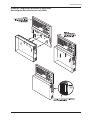
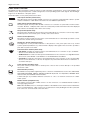
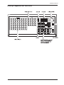
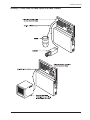
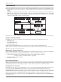
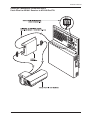
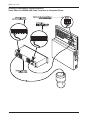
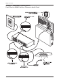
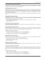
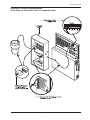
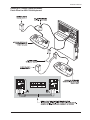
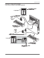
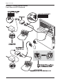
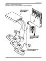
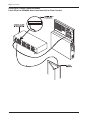
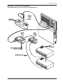
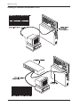
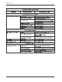
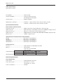
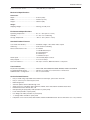
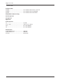
MegaPowerTM 48+
Installation Manual
MegaPowerTM 48+
DO NOT INSTALL THIS PRODUCT IN HAZARDOUS AREAS WHERE HIGHLY COMBUSTIBLE OR
EXPLOSIVE PRODUCTS ARE STORED OR USED
FCC Compliance
This equipment has been tested and found to comply with the limits for a Class A digital device, pursuant to Part 15 of
the FCC Rules. These limits are designed to provide reasonable protection against interference when the equipment is
operated in a commercial environment. The equipment generates, uses, and can radiate radio frequency energy and,
if not installed and used in accordance with the instruction manual, may cause interference to radio communications.
Operation of this equipment in a residential area may cause interference in which case the user will be required to
correct the interference at his own expense.
Equipment Modification Caution
Equipment changes or modifications not expressly approved by American Dynamics Video Products Division, the party
responsible for FCC compliance, could void the user’s authority to operate the equipment, and could create a hazardous
condition.
Warranty Disclaimer
American Dynamics Video Products Division makes no representation or warranty of the contents of this manual and
disclaims any implied warranties of merchantability or fitness. American Dynamics Video Products Division reserves
the right to revise this manual and change its content without obligation to notify any person of these revisions.
2
Installation Manual
Contents
FCC Compliance ..................................................................................................................................................................... 2
Equipment Modification Caution ........................................................................................................................................... 2
Warranty Disclaimer ............................................................................................................................................................... 2
Introduction ............................................................................................................................................................................. 5
MegaPower 48+ Assembly ..................................................................................................................................................... 5
Mechanical Installation ........................................................................................................................................................... 6
Start Up Diagnostics ........................................................................................................................................................... 6
Technical Support ............................................................................................................................................................... 6
Drawing 1: Wall Bracket Assembly ..................................................................................................................................... 7
Drawing 2: Patch Panel and Wall Bracket Assembly ......................................................................................................... 8
Drawing 3: Cable Management Bracket - Tie Wraps and Clips ......................................................................................... 9
Drawing 4: Patch Panel to Transformer Cable ................................................................................................................. 10
Drawing 5: Attaching the Main Electronics Unit (MEU) .................................................................................................... 11
Patch Panel Overview ........................................................................................................................................................... 12
Drawing 6: MegaPower 48 Patch Panel ........................................................................................................................... 13
System Programming ........................................................................................................................................................... 14
System Integration ................................................................................................................................................................ 14
AC Power Requirements ...................................................................................................................................................... 14
System Accessories ............................................................................................................................................................. 14
Video Connections ............................................................................................................................................................... 14
Drawing 7: Patch Panel to Video Inputs and Video Outputs ............................................................................................ 15
Cable Networks ..................................................................................................................................................................... 16
System Communications ..................................................................................................................................................... 16
Manchester Communications ........................................................................................................................................... 16
Daisy Chain Connections ........................................................................................................................................... 16
AD2083-02B Code Translator ..................................................................................................................................... 16
Drawing 8: Patch Panel to AD1641 Receiver to AD1240 Pan/Tilt .............................................................................. 17
Drawing 9: Patch Panel to AD2083-02B Code Translator to Integrated Dome .......................................................... 18
Drawing 10: Patch Panel to AD1691 Code Distributor to Integrated Dome ............................................................... 19
Drawing 11: Patch Panel to AD2031 Switcher Follower to Audio Circuit .................................................................... 20
Star Connections/AD1691 Code Distributor ............................................................................................................... 21
AD2031/2032/2033 Accessories ................................................................................................................................. 21
SensorNet Communications ............................................................................................................................................. 21
SensorNet Daisy Chain Configurations ...................................................................................................................... 21
Star Connections/6-Position J-Boxes ......................................................................................................................... 21
SEC-RS422 Communications .......................................................................................................................................... 21
RS422 Daisy Chain Connections ............................................................................................................................... 21
Star Connections/10-Position J-Boxes ....................................................................................................................... 21
Drawing 12: Patch Panel to 6-Position J-Box to Integrated Dome ............................................................................. 22
Drawing 13: Patch Panel to 10-Position J-Box to Integrated Dome ........................................................................... 23
RS232 Communications ................................................................................................................................................... 24
RS232 Keyboard Connections ................................................................................................................................... 24
Port Expander ............................................................................................................................................................. 24
Drawing 14: Patch Panel to ADCC1100 Keyboard ..................................................................................................... 25
Drawing 15: Patch Panel to ADCC0200 and ADCC0300 Keyboards ......................................................................... 26
Drawing 16: Patch Panel to AD2079 and AD2088 Keyboards ................................................................................... 27
Drawing 17: Patch Panel to ADTTE Keyboard ........................................................................................................... 28
Drawing 18: Patch Panel to AD1981 Port Expander to System Keyboards ............................................................... 29
PC Connection ............................................................................................................................................................ 30
RS232 External Modem Connection .......................................................................................................................... 30
RS232 Alarm Interface Unit Connection ..................................................................................................................... 30
RS232 Peripheral Interface Port Connection ............................................................................................................. 30
Drawing 19: Connections to PC and External Modem ............................................................................................... 31
Drawing 20: Patch Panel to AD2096A Alarm Interface Unit to Alarm Contact ........................................................... 32
Drawing 21: Video Recorder Control via ADCC1100 Keyboard ................................................................................. 33
Drawing 22: Ethernet Connections to a PC ................................................................................................................ 34
3
MegaPowerTM 48+
Direct Alarm and Relay Connections .................................................................................................................................. 35
Relay Outputs ................................................................................................................................................................... 35
Patch Panel Alarms .......................................................................................................................................................... 35
System Alarm Handling .................................................................................................................................................... 35
Drawing 23: Patch Panel Alarms and Relay Sections ...................................................................................................... 36
Multi-Matrix Configurations ................................................................................................................................................. 37
Mode 0 Configuration ....................................................................................................................................................... 37
Mode 1 Configuration ....................................................................................................................................................... 37
Mode 2 Configuration ....................................................................................................................................................... 37
Mode 3 Configuration ....................................................................................................................................................... 37
Mechanical Installation of Multiple Matrices ...................................................................................................................... 38
Network Connections in a Multi-Matrix System ................................................................................................................ 38
Video Connections in a Multi-Matrix System ..................................................................................................................... 40
Mode 1 Configurations ...................................................................................................................................................... 40
Mode 2 Configurations ...................................................................................................................................................... 43
Mode 3 Configurations ...................................................................................................................................................... 47
RS232 Connections in a Multi-Matrix System .................................................................................................................... 51
PC Connection in a Multi-Matrix System ............................................................................................................................ 51
Manchester, SensorNet and SEC-RS422 Connections in a Multi-Matrix System ........................................................... 51
Alarm Connections in a Multi-Matrix System ..................................................................................................................... 51
Control Addressing Quick Look-Up Table .......................................................................................................................... 54
MegaPower 48+ System Troubleshooting .......................................................................................................................... 55
Declaration of Conformity .................................................................................................................................................... 57
MegaPower 48+ Product Specifications ............................................................................................................................. 58
4
Installation Manual
Introduction
The MegaPower 48+ matrix switcher/controller is a video routing system with a broad range of functionality. The unit
has a compact, wall-mount design enabling it to be installed in the most centralized location with respect to the video
inputs. The unit can also be mounted behind other equipment in the rear of a rack at 90° to conserve space for other
products or it can be rack mounted at other angles to facilitate easy cable connections.
Each MegaPower 48+ unit has the following functionality:
•
48 video input connections for cameras or domes that can be viewed and controlled using SEC-RS422, AD Manchester
and SensorNet communication protocols.
• 16 video outputs. Outputs 1-8 provide video and a text overlay with status and alarm information. Outputs 9-16
provide video without text for uses such as public monitors.
• 2 form C relay outputs.
• 16 normally open alarm contact terminals.
• A diagnostics section providing power and unit operating status and a push-button system reset switch.
• Power terminals that connect to a 24 VAC transformer for either 120 VAC or 230 VAC inputs.
• 8 RS232 ports, enabling connection to system keyboards (ADCC1100, ADCC0200, ADCC0300, AD2079, AD2088
and ADTTE Touch Trackers®), printers, PCs, auxiliaries, alarm interface units, external modems for paging functions
and an interface for video recorders.
• When used with the ADCC1100 keyboard, the system has macro programming and synchronization capability, and
can control up to 2048 video recorders.
MegaPower 48+ units can be connected together in a multi matrix configuration. By connecting a primary matrix with six
secondary matrices, a MegaPower 48+ system comprising 288 video inputs with 8 full cross point switched primary
monitors and seven additional monitor outputs on each secondary unit can be built.
MegaPower 48+ Assembly
The MegaPower 48+ assembly is designed for vertical suspension hollow-wall or solid wall mounting. An optional rackmount kit is also available. The MegaPower 48+ assembly and accessories are shipped to the user in two boxes.
Box 1 contains the hardware and accessories necessary for the first stage of MegaPower 48+ installation. Box 2
contains the hardware necessary to complete the installation, and also contains the system manuals and software
disks. Keep Box 2 in a clean, secure location while the first stage of installation is in progress. After the first stage is
complete and debris is removed, bring Box 2 to the area to complete the installation in a clean workspace.
Box 1: PN 0100-0490-01
Description
Box 2: PN 0100-0491-51 (NTSC) or -52 (PAL)
Qty Part Number
Description
1
0500-5606-01
Main Electronics Unit, NTSC
1
0300-1843-01
Patch Panel Assy
1
0300-1642-01
Main Electronics Unit, PAL
1
0300-1843-02
Cable Mgt Bracket
1
0500-5656-01
Transformer (USA)
1
0300-1889-01
Cable Mgt Tie Kit:
1
0351-1345-01
Transformer (International)
1
0300-1889-03
AC Line Cord (USA)
1
0351-0547-01
AC Line Cord (EU)
1
0351-0547-02
AC Line Cord (UK)
1
0351-0547-03
Tie Wrap Clips
Wall Mount Hardware Kit:
12
1
Toggle Bolts
6
Bolt Anchors
6
Installation Template
Accessory Kit:
0351-1342-01
AC Line Cord (Japan)
1
0351-0547-04
1
8000-1797-01
AC Line Cord (Australia)
1
0351-0547-07
1
0351-1341-01
Document Kit (English)
1
0351-1338-51
Cables with Junction Boxes
3
Installation Manual
1
8000-1803-51
S3 Cable w/ DB9F Adaptor
1
Programming Manual
1
8000-1804-51
Patch Panel Hardware Kit
M4x6 Flathead Screws
Mounting Instructions
1
0351-1343-01
2
5801-2042-120
1
8000-1800-01
The following tools may also be required:
•
Qty Part Number
Mounting Bracket
Medium Phillips Head Screwdriver
•
Small Slotted Screwdriver
•
Level
•
Tie Wraps
•
BNC Removal Device
•
Marking Implement (Pen or Pencil)
•
Power Drill with drill bit: 11/16" (17.5mm), hollow wall, 1/2" (12.7mm), solid wall
5
MegaPowerTM 48+
Mechanical Installation
1. Remove the components from Box 1 and arrange them on a surface near the mounting location.
2. Remove and discard the red shipping knobs attached to the patch panel assembly. The knobs are used only for
factory packaging and must be removed prior to installation.
3. Using a level, position the installation template where the assembly is to be mounted. Provide at least 14" (36cm)
clearance from the bottom edge of the mounting bracket (which is the first component of the assembly to be
installed) to accommodate the entire assembly. Temporarily tape the template to the wall.
4. Using the template, carefully mark the drill points on the mounting surface. Make sure that the drill points are
positioned where there are no obstructions behind the wall surface. Remove the template and drill the holes for the
supplied hardware.
5. Depending on the wall type, secure the mounting bracket using the four bolts or screws provided. Secure the
mounting bracket using the four bolts or screws provided (see Drawing 1, Page 7).
6. Position the patch panel such that the screw holes in the mounting bracket’s two lower mounting hooks are aligned
exactly with the two corresponding holes on the patch panel assembly. Install the two M4x6 flathead screws using a
Phillips head screwdriver (see Drawing 2, Page 8).
7. Insert cable tie-wrap clips into the desired holes on the cable management bracket. Secure the cable management
bracket to a surface near the patch panel assembly. Attach system cables to the appropriate patch panel connectors.
Arrange cables in manageable groupings and secure the groups to the cable management bracket by means of tie
wraps looped through the tie wrap clip slots (see Drawing 3, Page 9).
Completion of the assembly requires connection of the transformer with AC line cord, and attachment of the Main
Electronics Unit.
8. Remove the hardware from Box 2. Connect the transformer cable to the the female power connector on the patch
panel as shown in Drawing 4, Page 10. Then connect the cable to the AC power outlet.
Note that to exercise sound practice, it is recommended that the MegaPower 48+ system and critical system
components be connected to an uninterruptible power supply to insure continuous operation during limited power
outages. The system so equipped will meet or exceed the requirements of EN 50130-4.
9. Fit the Main Electronics Unit on the patch panel assembly’s three guide hooks (see Drawing 5, Page 11).
10. Push upwards, with even pressure on the two lower corners of the Main Electronics Unit, until the unit mates
securely with the patch panel receptacles, and a distinct click is heard when the locking pins engage.
The main electronics unit can be disengaged from the patch panel assembly by pressing the two side triggers and
pulling to the side and down simultaneously, alternately moving from left to right, in three or four short, gentle,
movements.
11. When the Main Electronics Unit is connected, the system will start.
Start Up Diagnostics
When the Main Electronics Unit is connected with power applied, normal operation is indicated by the following:
• The ventilation fan is audible.
• The AC power LED (sine wave icon) in the upper right-hand section of the
patch panel illuminates.
• The UOP LED (heartbeat icon) blinks.
Note
The four yellow LEDs beneath the AC power LED are not operative with this version
of the system.
Patch Panel Diagnostics Section
If normal operation is indicated, call a monitor with a system keyboard, and then call a camera to the called monitor.
If the event of absent or abnormal diagnostic signals, power the system down and re-check system connections. If
necessary, consult Troubleshooting on page 55.
Technical Support
If you need assistance, please contact your American Dynamics representative.
6
Installation Manual
Drawing 1: MegaPower 48+ Mechanical Installation
Wall Bracket Assembly
7
MegaPowerTM 48+
Drawing 2: MegaPower 48+ Mechanical Installation
Patch Panel and Wall Bracket Assembly
8
Installation Manual
Drawing 3: MegaPower 48+ Mechanical Installation
Cable Management Bracket - Tie Wraps and Clips
9
MegaPowerTM 48+
Drawing 4: AC Power Section
Patch Panel to Transformer Cable
10
Installation Manual
Drawing 5: MegaPower Mechanical Installation
Attaching the Main Electronics Unit (MEU)
11
MegaPowerTM 48+
Patch Panel Overview
The MegaPower 48+ patch panel contains 8 sections for video switching, communications, power, alarm handling, and
auxiliary control. The patch panel also contains a diagnostics section providing system status signals. See Drawing 6,
Page 13 for an illustration of the patch panel.
A brief description of each patch panel section follows.
Video Inputs Section (Camera Icon)
The video inputs section provides 48 BNC connectors for connection of RG-59U video cables to system
cameras and domes. Cable distance should not exceed 1000 feet (330 meters).
Video Outputs Section (Monitor Icon)
The video outputs section provides 16 BNC connectors for connection to system video monitors and/or
recorders. Monitors 1-8 display video and a text overlay that provides information about the displayed
video. Monitors 9-16 display video with no text overlay.
Relay Section (Switch Icon)
The relay section provides two three-position screw terminal blocks for connection of form C relay outputs.
Terminal positions are normally open, normally closed, and common.
Alarms Section (Bell Icon)
The alarms section provides two 16-position screw terminal blocks for 16 normally open alarm contact
closure wires and 16 alarm ground wires.
Diagnostics Section (Wave Form Icon)
The diagnostics section provides indicators for the presence of AC power (sine wave icon), normal
system operation (heartbeat icon), and four LEDs to display status signals. This section also provides a
push button system reset switch.
Communications Section (Dome Icon)
• SEC-RS422: Provides two twelve-position screw terminal blocks for connection of up to six RS422
devices such as AD domes and J-Boxes.
• AD Manchester: Provides one three-position terminal block for the connection of a single Manchester
device such as the AD1691 Code Distributor or the AD1641M Receiver/Driver.
• SensorNet: Provides two six-position screw terminal blocks for the connection of up to six SensorNet
devices such as AD domes or J-Boxes. An adjacent six position DIP switch allows for termination of
each SensorNet port.
Power Section (Sine Wave Icon)
The power section provides either a female power connector that connects directly to the provided
transformer cable.
RS232 Section (PC Icon)
The RS232 section provides eight RJ45 jacks for connection of RS232 devices such as PCs, ADCC1100,
ADCC0200, ADCC0300, AD2079, AD2088 and ADTTE keyboards, Port Expanders, AD2096A Alarm
Interface Units, and standard external modems.
A ninth RJ45 jack is provided for Ethernet connection to a PC or for network connections in a multimatrix system.
Modem Section (Telephone Icon)
The modem section provides a DB9 connector for the connection of a standard external modem for
message paging functions.
Note: either the DB9 connector or RJ45 jack number 8 of the RS232 section can be used as an alternative
port for an external device - either connector is recognized as Port 8 by the MegaPower 48+ system, but
both connectors cannot be used at the same time.
12
Installation Manual
Drawing 6: MegaPower 48+ Patch Panel
13
MegaPowerTM 48+
System Programming
MegaPower 48+ can be programmed with a system keyboard and monitor using software embedded in the system’s
Main Electronics Unit, or with a PC and the Easy 48 software.
Instructions for programming are provided in the MegaPower 48+ System Programming and Operating Manual, part
number 8000-1804-51.
System Integration
The MegaPower 48+ system can also be integrated with other American Dynamics security systems and devices.
Among the products available for integration are:
•
C-Cure 800 Security Management System
•
Intellex Digital Video Management System
•
Integra Digital Time Lapse Recorder
Additional Integration Documentation
•
Intellex Digital Video Management System Installation Instructions
•
Integra Time Lapse Recorder Installation/Operation Manual
AC Power Requirements
Power is supplied to the MegaPower 48+ patch panel via a center-tapped transformer (see Drawing 4, Page 10).
•
Transformer (USA): 0300-1889-01
•
Transformer (International): 0300-1889-03
Input voltage: 120 V @ 630 mA, 50-60 Hz
Input voltage: 230 V @ 315 mA, 50-60 Hz
AC leads are black and white. Ground is red.
AC leads are brown and blue. Ground is green/yellow.
Cable required: 3 conductor, unshielded, 18 AWG.
Cable required: 3 conductor, unshielded, 18 AWG.
To exercise sound practice, it is recommended that the MegaPower 48 system and critical system components
be connected to an uninterruptible power supply to ensure continuous operation during limited power
outages. The system, so equipped, will meet or exceed the requirements of EN 50130-4.
System Accessories
Connections are made to and from various system devices and the MegaPower 48+ patch panel. In some cases,
simple, direct connections can be made from device to panel. In other cases, system accessories are utilized to implement
appropriate system operation.
MegaPower 48+ system accessories include the following:
•
AD2031 Switcher Follower
•
AD2032 Alarm Responder
•
AD2033 Auxiliary Follower
•
AD1641 Series Receivers
•
AD1981 Port Expander
•
AD2083-02B Code Translator
•
AD1691 Code Distributor
•
AD2096A Alarm Interface Unit
•
J-Boxes
•
AD100 Series Recorder Control Interfaces
Video Connections
•
Video cable required for both inputs and outputs: RG-59U (Belden 8241 or equivalent).
•
Maximum cable length: 1000 feet (305m)
•
Video standards supported: NTSC, PAL
•
Output termination requirements: 75 ohms at the last unit in the run.
•
Video cables should be labeled with an identifier associated with the appropriate BNC connector on the patch panel.
See Drawing 7, Page 15 for an illustration of typical video inputs and video outputs.
14
Installation Manual
Drawing 7: Patch Panel to Video Inputs and Video Outputs
15
MegaPowerTM 48+
Cable Networks
Cable networks provide the means through which the MegaPower 48+ Main Electronics Unit communicates with receiver/
driver units and domes. Three types of networks can be used with the Manchester, SensorNet, or SEC-RS422 protocols.
•
Daisy Chain – in a daisy chain configuration, a separate cable connects each device to the next device in the chain
(Fig. A).
•
Backbone – in a backbone configuration, a single, continuous cable connects all domes in the network link (Fig. B).
•
Star – in a star configuration, up to four branches connect to a central hub location (typically a J-Box or other data
distribution unit). Domes can attach with separate cables (daisy chain style) as shown in Fig.C, or, with a single
continuous cable (backbone style) as shown in Fig. D.
Note: both ends of a cable run must be terminated. Black device blocks illustrated above indicate terminated devices.
System Communications
The MegaPower 48+ CPU communicates with system devices through four communications protocols:
• RS232 (PC icon)
• SEC-RS422 (dome icon)
• SensorNet (dome icon)
• Manchester (dome icon)
RS422, SensorNet and Manchester protocols are used in the control of domes and pan/tilt cameras.
RS232 enables communications with system keyboards, PCs, auxiliaries, alarm interface units, external modems, port
expanders, and video recorder interface units.
Manchester Communications
There is a single Manchester connector on the MegaPower 48+ patch panel. The connector consists of three terminals
labeled Black (B), White (W), and Shield (S). Manchester is a one-way communications protocol.
•
•
•
Cable required: 18 AWG, 2-wire, shielded twisted pair. polarized, Belden 8760 or equivalent
For Plenum applications, Belden 88760 or equivalent
Maximum distance: 5000 feet (1.5km)
Data rate: 31 kb/sec
Daisy Chain Connections
When wired directly from the patch panel connector to a receiver/driver or integrated dome in a Manchester network, a
maximum of three video sources can be connected via a daisy chain connection. The last unit in the daisy chain must
be terminated at 120 ohms. See Drawing 8, Page 17 for a typical direct connection to an AD1641 Receiver.
AD2083-02B Code Translator
The MegaPower 48+ CPU can output Manchester code to control domes utilizing the SEC-RS422 communications
protocol by using the AD2083-02B Code Translator as an interface between the patch panel and the domes.
A single AD2083-02B provides 16 terminals using the 4-wire RS422 protocol. DIP switches on the rear panel of the
AD2083-02B enable addressing for specific groups of cameras. All 48 video inputs for the MegaPower 48+ patch panel
can be connected through a single AD2083-02B by wiring each terminal to a three-dome daisy chain group.
See Drawing 9, Page 18 for a typical connection from the MegaPower 48+ Manchester terminals to an AD2083-02B to
an integrated dome.
16
Installation Manual
Drawing 8: Manchester Communications
Patch Panel to AD1641 Receiver to AD1240 Pan/Tilt
17
MegaPowerTM 48+
Drawing 9: Manchester Communications
Patch Panel to AD2083-02B Code Translator to Integrated Dome
18
Installation Manual
Drawing 10: Manchester Communications
Patch Panel to AD1691 Code Distributor to Integrated Dome
19
MegaPowerTM 48+
Drawing 11: Manchester Communications
Patch Panel to AD2031 Switcher Follower to Audio Circuit
20
Installation Manual
Star Connections/AD1691 Code Distributor
When the patch panel’s Manchester black, white, and shield terminals are wired to the input terminals of an AD1691
Code Distributor, up to 64 Manchester outputs can be transmitted to receiver/drivers and integrated domes. See Drawing
10, Page 19 for a typical connection utilizing the AD1691.
AD2031/2032/2033 Accessories
The MegaPower 48+ CPU can output Manchester code to control external circuit switching synchronized with the
switching of video inputs to video outputs (via the AD2031 Switcher Follower). It can also synchronize external circuits
with the switching of auxiliary contacts associated with individual video inputs (via the AD2033 Auxiliary Follower).
Additionally, it can provide relay contact closures for corresponding video outputs that are displaying alarm conditions
(via the AD2032 Alarm Responder).
See Drawing 11, Page 20 for a typical connection of the patch panel to an AD2031 synchronized with an external audio
circuit.
SensorNet Communications
SensorNet is a two wire, two-way communications protocol. There are 12 screw terminals on the MegaPower 48+ patch
panel providing six channels for SensorNet communications. Directly below the SensorNet screw terminals is a DIP
switch that is used to terminate each of the six channels.
•
•
•
Cable required: 22 AWG, single twisted pair, unshielded, non-polarized. Belden 8442 or equivalent
Maximum distance: 3300 feet (1 km)
Data rate: 230 kb/sec
SensorNet Daisy Chain Configurations
Each SensorNet patch panel terminal pair can be wired directly to eight-dome daisy chain groups to accommodate all
48 video inputs available to MegaPower 48+.
Star Connections/6-Position J-Boxes
Each SensorNet patch panel terminal can be wired to a 6-position J-box. The J-Box serves as a hub for star connections
for up to 6 domes. Each J-Box-to-dome connection can also serve as the starting point for a daisy chain group. See
Drawing 12, Page 22 for a typical connection of the patch panel to a 6-position J-box.
Additional SensorNet Documentation
•
SensorNet 1-Position J-Box Installation Guide — part number 8000-0971-01
•
SensorNet 6-Position J-Box Installation Guide — part number 8000-0975-01
•
SensorNet Network Design Guidelines — part number 8000-0970-01
SEC-RS422 Communications
RS422 is a four wire, two way communications protocol. There are 24 screw terminals on the MegaPower 48+ patch
panel providing six four–terminal channels for RS422 communications.
•
•
•
Cable required: 22 AWG, four conductor, double twisted pair (polarized)
Maximum distance: 3000 feet (915m)
Data rate: 4.8 kb/sec
RS422 Daisy Chain Connections
Each RS422 patch panel four terminal group can be wired directly to eight-dome daisy chain groups to accommodate
all 48 video inputs available to MegaPower 48+.
Star Connections/10-Position J-Boxes
Each RS422 patch panel terminal group can be wired to a 10-position J-box. The J-Box serves as a hub for star
connections for up to 10 domes. All 48 video inputs can be accommodated using six 10-position J-boxes, with each JBox connected to six domes. See Drawing 13, Page 23 for a typical connection of the patch panel to a 10-position Jbox.
Additional RS422 Documentation
•
RS422 1-Position J-Box Installation Guide — part number 8000-0588-01
•
RS422 10-Position J-Box Installation Guide — part number 8000-0320-01
•
Communications Protocols and Cable Networks — part number 8000-2573-19
21
MegaPowerTM 48+
Drawing 12: Sensornet Communications
Patch Panel to 6-Position J-Box to Integrated Dome
22
Installation Manual
Drawing 13: RS422 Communications
Patch Panel to 10-Position J-Box to Integrated Dome
23
MegaPowerTM 48+
RS232 Communications
The RS232 section (PC icon) of the MegaPower 48+ patch panel consists of eight RJ45 receptacles and one DB9
receptacle.
•
•
•
Cable required: modular eight conductor cable, cable distance (7 or 14 feet) and plug dependent on application.
Accessories: wall-mount keyboard matrix interface (MP-KMI) and wall-mount eight pin terminal box. Box can be
single or dual mount dependent on application.
Additional Cable: 18 AWG, three-wire, shielded cable. Maximum cable distance of 1000 feet (305m).
RS232 Keyboard Connections
The MegaPower 48+ can utilize any of the following six keyboards: ADCC1100, ADCC0200, ADCC0300, AD2079,
AD2088, and ADTTE Touch Tracker.
ADCC1100
ADCC1100 provides the user with the largest features set, including flexible macro programming and system partitioning
with smart card access control and user management. The ADCC1100 is connected to the MegaPower 48+ patch panel
by a seven foot modular cable with RJ45 plugs, and a MP-KMI keyboard matrix interface. Power to the keyboard is
provided by a transformer connected to the MP-KMI. For connections greater than seven feet, an additional MP-KMI is
used with 3-wire, 18 AWG shielded cable. Maximum cable length = 1000 feet (305m). See Drawing 14, Page 25 for a
typical connection using the ADCC1100 keyboard.
ADCC0200 and ADCC0300
The ADCC0200 and ADCC0300 keyboards are connected to the MegaPower 48+ patch panel by a seven foot modular
cable with RJ45 plugs, and a MP-KMI keyboard matrix interface. Power to the keyboard is provided by a transformer
connected to the MP-KMI. For connections greater than seven feet, an additional MP-KMI is used with 3-wire, 18 AWG
shielded cable. Maximum cable length = 1000 feet (305m). See Drawing 15, Page 26 for a typical connection using the
ADCC0200 keyboard.
AD2079 and AD2088
The AD2079 and AD2088 keyboards are connected to the MegaPower 48+ patch panel by a seven foot modular cable
with RJ45 plugs, and a dual 8-pin wall mount terminal box. Power to the keyboard is provided by a transformer connected
to the terminal box. For connections greater than seven feet, an additional single 8-pin terminal box is used with 3-wire,
18 AWG shielded cable. Maximum cable length = 1000 feet (305m). See Drawing 16, Page 27 for a typical connection
using the AD2088 keyboard.
ADTTE Touch Tracker
The ADTTE Touch Tracker keyboard connects to an EIM module via an 8 conductor, 14 foot modular cable with RJ45
plugs. MegaPower 48+ RS232 ports connect to the EIM module via an 8 conductor cable with an RJ45 plug at one end,
and a DB9M connector at the other end. Power is provided to the keyboard via a transformer connected to the EIM
module via a 5 pin screw terminal connector. For connections greater than 14 feet, two single 8-pin wall mount terminal
boxes are used with the EIM module and 3-wire, 18 AWG shielded cable. Maximum cable length = 1000 feet (305m).
See Drawing 17, Page 28 for a typical connection using the ADTTE keyboard.
Port Expander
An RS232 port with keyboard device type assignment can be connected to up to four keyboards through the use of the
AD2081 Port Expander. The RS232 port is connected to an RJ45 CPU input receptacle on the Port Expander via a
seven foot modular cable with RJ45 plugs. The keyboards are then wired from any of the four Port Expander output
ports using the configurations discussed in the sectionRS-232 Keyboard Connections above. See Drawing 18, Page
29 for a typical connection using the AD2081 Port Expander.
24
Installation Manual
Drawing 14: RS232 Communications
Patch Panel to ADCC1100 Keyboard
25
MegaPowerTM 48+
Drawing 15: RS232 Communications
Patch Panel to ADCC0200 and ADCC0300 Keyboards
26
Installation Manual
Drawing 16: RS232 Communications
Patch Panel to AD2079 and AD2088 Keyboards
27
MegaPowerTM 48+
Drawing 17: RS232 Communications
Patch Panel to ADTTE Keyboard
28
Installation Manual
Drawing 18: RS232 Communications
Patch Panel to AD1981 Port Expander to System Keyboards
29
MegaPowerTM 48+
PC Connection
A PC can be connected to the MegaPower 48+ for the purpose of downloading system setup software parameters to
the system, or uploading system parameters to the PC. This connection can be via RS232 using a RS232 port on the
MegaPower 48+ or via an Ethernet connection using the network connector on the MegaPower 48+.
Ethernet
An Ethernet connection can be made between the network connector on the MegaPower 48+ and a PC using a crossover cable or using a straight connection via an Ethernet switch. All Ethernet connections should be made with Cat 5
twisted pair cable with a maximum length of 300 feet. If longer connections are required, hubs and repeaters are
available. See Drawing 22, Page 34 for typical MegaPower 48+ to PC Ethernet connections.
RS232
An RS232 connection can be made between the MegaPower 48+ and a PC by connecting a seven foot (2.2 m) modular
cable with RJ45 plugs to the DB9M on one of the PC’s COM ports using a converter with an RJ45 receptacle and a
DB9F connector. See Drawing 19, Page 31 for a typical MegaPower 48+ RS232 port to PC connection.
RS232 External Modem Connection
Port 8 of the MegaPower 48+ patch panel RS232 section has two different connectors. A DB9M connector is provided
for connection to an external AT command set modem. Any other device assigned to port 8 is connected to the RJ45
receptacle. Note that only one device can be connected to port 8. Both receptacles cannot be connected
simultaneously.
Connection to a modem is made using a modular seven foot cable with DB9F and DB25M connectors at the cable
ends. The modem can be connected to analog telephone lines only. See Drawing 19, Page 31 for a typical MegaPower
48+ RS232 port to modem connection.
RS232 Alarm Interface Unit Connection
The AD2096A Alarm Interface Unit (AIU) can be connected to any one of the eight RS232 ports on the MegaPower 48+
patch panel. The MegaPower 48+ port is connected to the RJ45 COM OUT receptacle on the rear panel of the AD2096A
via a seven foot modular cable. For connections greater than seven feet, two single, 8-pin terminal boxes are used with
3 wire, 18 AWG, shielded cable. Maximum cable length = 1000 feet (305m).
The AD2096A rear panel also contains a DIP switch for selection of normally-open or normally-closed status for the
alarm contact relays, and a DIP switch that selects the appropriate alarm contact group (1-64, 65-128, 129-192, etc.).
The MegaPower 48+ system can accept up to 512 RS232 alarm inputs. Each AD2096A can be connected to up to 64
alarm contacts. Up to seven additional AD2096A units can be cascaded via the RJ45 COM IN receptacles to accommodate
additional alarm contacts.
See Drawing 20, Page 32 for a typical MegaPower 48+ RS232 port to AD2096A connection.
Additional AD2096A Documentation
• AD2096A Alarm Interface Unit Installation and Operating Instructions — part number 8000-0888-01
RS232 Peripheral Interface Port Connection
MegaPower 48+ embedded software and system setup software provide the user with a system option to enable one
Peripheral Interface Port (PIP).
For MegaPower 48+ release 1.0, a PIP will connect to an AD100 series video recorder interface for control of up to 1024
video recorders. Control is implemented with the ADCC1100 keyboard. The MegaPower 48+ RS232 PIP connects to an
AD-100XA (or AD100XA-1) Recorder Controller via a seven foot modular cable with a DB9M connector. The DB9M
connects to the RS232 port on the AD100XA.
See Drawing 21, Page 33 for a typical MegaPower 48+ RS232 port to peripheral interface port connection.
Additional PIP Documentation
• AD100 Series Recorder Controller & IR Interface Hookup/Software Utility Installation & Operating Instructions —
part number 8000-1796-01
30
Installation Manual
Drawing 19: RS232 Communications
Connections to PC and External Modem
31
MegaPowerTM 48+
Drawing 20: RS232 Communications
Patch Panel to AD2096A Alarm Interface Unit to Alarm Contact
32
Installation Manual
Drawing 21: RS232 Communications
Video Recorder Control via ADCC1100 Keyboard
33
MegaPowerTM 48+
Drawing 22: Ethernet Connections to a PC
34
Installation Manual
Direct Alarm and Relay Connections
Relay Outputs
The MegaPower 48+ patch panel provides a section for direct connection to two normally-open or normally-closed relay
outputs for switching of auxiliary devices such as lights, gates, audio alerts, recorders, etc.
Patch Panel Alarms
The MegaPower 48+ patch panel provides 16 screw terminals and corresponding ground returns for direct connection
to normally-open alarm contacts. These connections are referred to as “patch panel” alarms. Patch panel alarms are
connected with shielded, two-wire cable. Both the shield and ground wires must be connected to the ground terminals
in the patch panel alarm section.
System Alarm Handling
The total alarm handling capability of a single MegaPower 48+ is provided by 16 patch panel alarms, 512 RS232 alarms
wired through the AD2096A Alarm Interface Unit, 192 dome alarms (up to 48 domes, with four alarm contacts per
dome), and up to 48 video loss alarms that are generated when a loss of video sync is detected at a video input.
See Drawing 23, Page 36 for typical direct alarm and relay connections to a single MegaPower 48+ unit.
35
MegaPowerTM 48+
Drawing 23: Patch Panel Alarms and Relay Sections
36
Installation Manual
Multi-Matrix Configurations
MegaPower 48+ units can be connected together in multi-matrix systems. A primary MegaPower 48+ matrix can be
connected with up to six secondary matrices, creating a maximum system capacity of 288 video inputs with eight full
cross point switched monitor outputs and seven additional monitor outputs on each secondary unit (for viewing of video
from that secondary unit only).
When creating a multi-matrix system, an Operation Mode must be specified, and this is done using either the software
embedded in the system’s Main Electronics Unit, or with a PC interface and the Easy 48 configuration software. See the
appropriate handbook for more details.
The mode that is specified determines how the matrices will be connected together and how many video inputs and
outputs are available in the system. Four modes are available—Mode 0, Mode 1, Mode 2 and Mode 3.
Mode 0 Configuration
A Mode 0 configuration has no secondary matrices and is a single 48 video input, 16 monitor output unit. Connections
are all made to a single matrix unit as explained earlier in this manual.
Mode 1 Configuration
A Mode 1 configuration has a primary matrix and a maximum of three secondary units, with 16 monitor outputs from
each secondary matrix connected to 16 video inputs on the primary matrix.
In a Mode 1 system, the maximum capacity is:
•
144 cameras.
•
16 full cross point switched monitor outputs with on-screen text display on monitors 1-8. Note that if video loss
detection is enabled in the system, Monitor 16 will be unavailable for selection.
•
32 RS232 ports for keyboards, port expanders and other supported devices.
Each connected matrix can also have 16 patch panel alarm inputs and 2 alarm outputs, four dome camera alarm inputs
per connected AD dome (SensorNet or SEC-RS422 only) and 48 video loss alarms. A maximum of 512 RS232 alarms,
wired through the AD2096A Alarm Interface Unit, can be included in a system.
Mode 2 Configuration
A Mode 2 configuration has a primary matrix and a maximum of four secondary units, with 12 monitor outputs from each
secondary matrix connected to 12 video inputs on the primary matrix.
In a Mode 2 system, the maximum capacity is:
• 196 cameras.
• 12 full cross point switched monitor outputs with on-screen text display on monitors 1-8. Also, 3 monitor outputs are
available on each secondary unit, capable of displaying video inputs from that secondary unit only. All secondary
monitors can display on-screen text. On all matrices, monitor 16 is reserved for video-loss detection.
• 40 RS232 ports for keyboards, port expanders and other supported devices.
Each connected matrix can also have 16 patch panel alarm inputs and 2 alarm outputs, four dome camera alarm inputs
per connected AD dome (SensorNet or SEC-RS422 only) and 48 video loss alarms. A maximum of 512 RS232 alarms,
wired through the AD2096A Alarm Interface Unit, can be included in a system.
Mode 3 Configuration
A Mode 3 configuration has a primary matrix and a maximum of six secondary units, with 8 monitor outputs from each
secondary matrix connected to 8 video inputs on the primary matrix.
In a Mode 3 system, the maximum capacity is:
•
288 cameras.
•
8 full cross point switched monitor outputs with on-screen text display on monitors 1-8. Also, 7 monitor outputs are
available on each secondary unit, capable of displaying video inputs from that secondary unit only. All secondary
monitors can display on-screen text. On all matrices, monitor 16 is reserved for video-loss detection.
•
56 RS232 ports for keyboards, port expanders and other supported devices.
Each connected matrix can also have 16 patch panel alarm inputs and 2 alarm outputs, four dome camera alarm inputs
per connected AD dome (SensorNet or SEC-RS422 only) and 48 video loss alarms. A maximum of 512 RS232 alarms,
wired through the AD2096A Alarm Interface Unit, can be included in a system.
Note
When configuring a multi-matrix system using the software embedded in the system’s Main Electronics Unit or with the
Easy 48 configuration software, all ports are listed by port reference. In this reference, the first character is the matrix
reference (X = primary unit, A-F = secondary units) and the second character is the port number in that section of
connectors (e.g., video inputs, video outputs, RS232, alarms, etc). If a port expander has been fitted to a RS232 port,
an expander reference (a-d) is added to the end of the port reference.
37
MegaPowerTM 48+
Mechanical Installation of Multiple Matrices
Each MegaPower 48+ unit in a multi-matrix system must be installed and connected to a power supply as explained in
the mechanical installation procedure detailed on page 6.
Network Connections in a Multi-Matrix System
In a multi-matrix system, matrices can be connected together via Ethernet. All ethernet connections should be made
with Cat 5 twisted pair cable with a maximum length of 300 feet. If longer connections are required, hubs and repeaters
are available.
In a system with two matrices, connect the matrix units using a cross-over cable as shown in the following figure.
Connections should be made to the network connector on each matrix.
PRIMARY MATRIX
SECONDARY MATRIX
CROSS-OVER CABLE
CAT 5 CROSS-OVER CABLE CONNECTIVITY
PIN
PRIMARY MATRIX
SECONDARY MATRIX
1
2
3
4
5
6
7
WHITE/ORANGE
ORANGE
WHITE/GREEN
BLUE
WHITE/BLUE
GREEN
WHITE/BROWN
WHITE/GREEN
GREEN
WHITE/ORANGE
BLUE
WHITE/BLUE
ORANGE/GREEN
WHITE/BROWN
8
BROWN
BROWN
38
Installation Manual
In a multi-matrix system with more than two matrices, matrices must be connected together via a network switch as
shown in the figure below. It is preferable to use a true network switch rather than a hub as a switch only sends data to
the relevant port connection while a hub will copy the data to all ports. Straight connections should be made from the
network connector on each matrix to the network switch.
MEGAPOWER 48+
MEGAPOWER 48+
NETWORK SWITCH
CAT 5 STRAIGHT CABLE CONNECTIVITY
PIN
MATRIX
SWITCH
1
2
3
4
5
6
7
WHITE/ORANGE
ORANGE
WHITE/GREEN
BLUE
WHITE/BLUE
GREEN
WHITE/BROWN
WHITE/ORANGE
ORANGE
WHITE/GREEN
BLUE
WHITE/BLUE
GREEN
WHITE/BROWN
8
BROWN
BROWN
MEGAPOWER 48+
Once network connections have been made, the software embedded in the Main Electronics Unit of each unit must be
used to assign an IP address to that unit. Secondary matrices are programmed with the IP address for that matrix alone,
while the primary matrix must be programmed with the IP addresses of all connected matrices. See the Programming
and Operation manual for more details.
Once the matrices have been programmed with IP addresses, it is possible to continue to use the embedded software
for system configuration or you can use the Easy 48 configuration software.
39
MegaPowerTM 48+
Video Connections in a Multi-Matrix System
The video connections made in a multi-matrix system will depend on the operation mode that is being used.
In all following sections, the maximum number of trunk video connections are shown and by connecting in this manner,
the maximum number of full cross point switched monitor outputs can be achieved. It should be noted that if the number
of full cross point switched monitor outputs is lower, only this number of trunk video connections need to be made.
Mode 1 Configurations
Mode 1: Primary Matrix with 1 Secondary Matrix
Consult the figure below in order to connect video inputs and outputs to the system. The 16 monitor outputs from the
secondary matrix must be connected to video inputs 1-16 on the primary matrix. Sixteen full cross point switched
monitor outputs are available by connecting monitors to video outputs 1-16 on the primary matrix.
PRIMARY MATRIX
MONITORS 1-16
(PORT REFS. X1-X16)
CONNECT MONITOR OUTPUTS 1-16
ON SECONDARY MATRIX A TO VIDEO
INPUTS 1-16 ON PRIMARY MATRIX
CAMERAS 49-80
(PORT REFS. X17-X48)
CAMERAS 1-48
(PORT REFS. A1-A48)
SECONDARY MATRIX A
40
Installation Manual
Mode 1: Primary Matrix with 2 Secondary Matrices
Consult the figure below in order to connect video inputs and outputs to the system. The 16 monitor outputs from each
secondary matrix must be connected to 16 video inputs on the primary matrix. Sixteen full cross point switched monitor
outputs are available by connecting monitors to video outputs 1-16 on the primary matrix.
PRIMARY MATRIX
MONITORS 1-16
(PORT REFS. X1-X16)
CONNECT MONITOR OUTPUTS 1-16
ON SECONDARY MATRIX A TO VIDEO
INPUTS 1-16 ON PRIMARY MATRIX
CAMERAS 97-112
(PORT REFS. X33-X48)
CAMERAS 1-48
(PORT REFS. A1-A48)
SECONDARY MATRIX A
CONNECT MONITOR OUTPUTS 1-16
ON SECONDARY MATRIX B TO VIDEO
INPUTS 17-32 ON PRIMARY MATRIX
CAMERAS 49-96
(PORT REFS. B1-B48)
SECONDARY MATRIX B
41
MegaPowerTM 48+
Mode 1: Primary Matrix with 3 Secondary Matrices
Consult the figure below in order to connect video inputs and outputs to the system. The 16 monitor outputs from each
secondary matrix must be connected to 16 video inputs on the primary matrix. Sixteen full cross point switched monitor
outputs are available by connecting monitors to video outputs 1-16 on the primary matrix.
PRIMARY MATRIX
MONITORS 1-16
(PORT REFS. X1-X16)
CONNECT MONITOR OUTPUTS 1-16
ON SECONDARY MATRIX A TO VIDEO
INPUTS 1-16 ON PRIMARY MATRIX
CAMERAS 1-48
(PORT REFS. A1-A48)
SECONDARY MATRIX A
CONNECT MONITOR OUTPUTS 1-16
ON SECONDARY MATRIX B TO VIDEO
INPUTS 17-32 ON PRIMARY MATRIX
CAMERAS 49-96
(PORT REFS. B1-B48)
SECONDARY MATRIX B
CONNECT MONITOR OUTPUTS 1-16
ON SECONDARY MATRIX C TO VIDEO
INPUTS 33-48 ON PRIMARY MATRIX
CAMERAS 97-144
(PORT REFS. C1-C48)
SECONDARY MATRIX C
42
Installation Manual
Mode 2 Configurations
Mode 2: Primary Matrix with 1 Secondary Matrix
Consult the figure below in order to connect video inputs and outputs to the system. Monitor outputs 4-15 from the
secondary matrix must be connected to video inputs 1-12 on the primary matrix.
Twelve full cross point switched monitor outputs are available by connecting monitors to video outputs 1-12 on the
primary matrix. Monitors can also be connected to monitor outputs 1-3 on the secondary matrix. These monitors can
display video inputs from that secondary unit only.
On all matrices, video output 16 is reserved for video-loss detection.
Mode 2: Primary Matrix with 2 Secondary Matrices
Consult the figure below in order to connect video inputs and outputs to the system. Monitor outputs 4-15 from each
secondary matrix must be connected to 12 video inputs on the primary matrix.
PRIMARY MATRIX
Twelve full cross point switched monitor outputs are available by connecting monitors to video outputs 1-12 on the
primary matrix. Monitors can also be connected to monitor outputs 1-3 on each secondary matrix. These monitors can
display video inputs from that secondary unit only.
On all matrices,
video output
MONITORS
1-12 16 is reserved for video-loss detection.
(PORT REFS. X1-X12)
Mode 2: Primary Matrix with 3 Secondary Matrices
Consult the figure below in order to connect video inputs and outputs to the system. Monitor outputs 4-15 from each
secondary matrix must be connected to 12 video inputs on the primary matrix.
Twelve full cross point switched monitor outputs are available by connecting monitors to video outputs 1-12 on the
primary matrix. Monitors can also be connected to monitor outputs 1-3 on each secondary matrix. These monitors can
CAMERAS
49-84
display video
inputs from
that secondary unit only.
(PORT REFS. X13-X48)
On all matrices, video output 16 is reserved for video-loss detection.
CONNECT MONITOR OUTPUTS 4-15
ON SECONDARY MATRIX A TO VIDEO
INPUTS 1-12 ON PRIMARY MATRIX
Mode 2: Primary Matrix with 4 Secondary Matrices
Consult the figure below in order to connect video inputs and outputs to the system. Monitor outputs 4-15 from each
secondary matrix must be connected to 12 video inputs on the primary matrix.
Twelve full cross point switched monitor outputs are available by connecting monitors to video outputs 1-12 on the
primary matrix.
Monitors13-15
can also be connected to monitor outputs 1-3 on each secondary matrix. These monitors can
MONITORS
display video
inputs
from
that secondary unit only.
(PORT
REFS.
A1-A3)
On all matrices, video output 16 is reserved for video-loss detection.
Mode 3 Configurations
Mode 3: Primary Matrix with 1 Secondary Matrix
Consult the CAMERAS
figure below1-48
in order to connect video inputs and outputs to the system.
Monitor outputs
8-15
SECONDARY
MATRIX
A from the
(PORT
secondary matrixREFS.
must A1-A48)
be connected to video inputs 1-8 on the primary matrix.
Eight full cross point switched monitor outputs are available by connecting monitors to video outputs 1-8 on the primary
matrix. Monitors can also be connected to monitor outputs 1-7 on the secondary matrix. These monitors can display
video inputs from that secondary unit only.
On all matrices, video output 16 is reserved for video-loss detection.
Mode 3: Primary Matrix with 2 Secondary Matrices
Consult the figure below in order to connect video inputs and outputs to the system. Monitor outputs 8-15 from each
secondary matrix must be connected to 8 video inputs on the primary matrix.
Eight full cross point switched monitor outputs are available by connecting monitors to video outputs 1-8 on the primary
matrix. Monitors can also be connected to monitor outputs 1-7 on each secondary matrix. These monitors can display
video inputs from that secondary unit only.
On all matrices, video output 16 is reserved for video-loss detection.
Mode 3: Primary Matrix with 3 Secondary Matrices
Consult the figure below in order to connect video inputs and outputs to the system. Monitor outputs 8-15 from each
43
MegaPowerTM 48+
secondary matrix must be connected to 8 video inputs on the primary matrix.
Eight full cross point switched monitor outputs are available by connecting monitors to video outputs 1-8 on the primary
matrix. Monitors can also be connected to monitor outputs 1-7 on each secondary matrix. These monitors can display
video inputs from that secondary unit only.
On all matrices, video output 16 is reserved for video-loss detection.
Mode 3: Primary Matrix with 4 Secondary Matrices
PRIMARY MATRIX
MONITORS 1-12
(PORT REFS. X1-X12)
CAMERAS 97-120
(PORT REFS. X25-X48)
CONNECT MONITOR OUTPUTS 4-15
ON SECONDARY MATRIX A TO VIDEO
INPUTS 1-12 ON PRIMARY MATRIX
MONITORS 13-15
(PORT REFS. A1-A3)
CAMERAS 1-48
SECONDARY MATRIX A
(PORT REFS. A1-A48)
CONNECT MONITOR OUTPUTS 4-15
ON SECONDARY MATRIX B TO VIDEO
INPUTS 13-24 ON PRIMARY MATRIX
MONITORS 16-18
(PORT REFS. B1-B3)
CAMERAS 49-96
SECONDARY MATRIX B
(PORT REFS. B1-B48)
44
Installation Manual
Consult the figure below in order to connect video inputs and outputs to the system. Monitor outputs 8-15 from each
secondary matrix must be connected to 8 video inputs on the primary matrix.
Eight full cross point switched monitor outputs are available by connecting monitors to video outputs 1-8 on the primary
matrix. Monitors can also be connected to monitor outputs 1-7 on each secondary matrix. These monitors can display
video inputs from that secondary unit only.
On all matrices, video output 16 is reserved for video-loss detection.
PRIMARY MATRIX
MONITORS 1-12
(PORT REFS. X1-X12)
CAMERAS 145-156
(PORT REFS. X37-X48)
CONNECT MONITOR OUTPUTS 4-15
ON SECONDARY MATRIX A TO VIDEO
INPUTS 1-12 ON PRIMARY MATRIX
MONITORS 13-15
(PORT REFS. A1-A3)
CAMERAS 1-48
SECONDARY MATRIX A
(PORT REFS. A1-A48)
CONNECT MONITOR OUTPUTS 4-15
ON SECONDARY MATRIX B TO VIDEO
INPUTS 13-24 ON PRIMARY MATRIX
MONITORS 16-18
(PORT REFS. B1-B3)
CAMERAS 49-96
SECONDARY MATRIX B
(PORT REFS. B1-B48)
CONNECT MONITOR OUTPUTS 4-15
ON SECONDARY MATRIX C TO VIDEO
INPUTS 25-36 ON PRIMARY MATRIX
MONITORS 19-21
(PORT REFS. C1-C3)
CAMERAS 97-144
SECONDARY MATRIX C
(PORT REFS. C1-C48)
45
MegaPowerTM 48+
Mode 3: Primary Matrix with 5 or 6 Secondary Matrices
Consult the figures on page 52 and 53 in order to connect video inputs and outputs to the system. Monitor outputs 8-15
from each secondary matrix must be connected to 8 video inputs on the primary matrix.
Eight full cross point switched monitor outputs are available by connecting monitors to video outputs 1-8 on the primary
matrix. Monitors can also be connected to monitor outputs 1-7 on each secondary matrix. These monitors can display
video inputs from that secondary unit only.
On all matrices, video output 16 is reserved for video-loss detection.
CAMERAS 1-48
MONITORS 13-15
CAMERAS 145-192
MONITORS 22-24
(PORT REFS. A1-A48)
(PORT REFS. A1-A3)
(PORT REFS. D1-D48)
(PORT REFS. D1-D3)
SECONDARY MATRIX A
SECONDARY MATRIX D
CONNECT MONITOR OUTPUTS
4-15 ON SECONDARY MATRIX A
TO VIDEO INPUTS 1-12 ON
PRIMARY MATRIX
CONNECT MONITOR OUTPUTS
4-15 ON SECONDARY MATRIX D
TO VIDEO INPUTS 37-48 ON
PRIMARY MATRIX
PRIMARY MATRIX
MONITORS 16-18
MONITORS 1-12
(PORT REFS. B1-B3)
(PORT REFS. X1-X12)
CONNECT MONITOR
OUTPUTS 4-15 ON
SECONDARY MATRIX C TO
VIDEO INPUTS 25-36 ON
PRIMARY MATRIX
CONNECT MONITOR OUTPUTS
4-15 ON SECONDARY MATRIX B
TO VIDEO INPUTS 13-24 ON
PRIMARY MATRIX
SECONDARY MATRIX B
SECONDARY MATRIX C
CAMERAS 97-144
CAMERAS 49-96
(PORT REFS. C1-C48)
(PORT REFS. B1-B48)
MONITORS 19-21
(PORT REFS. C1-C3)
46
Installation Manual
RS232 Connections in a Multi-Matrix System
Keyboard and Port Expander Connection
Keyboards can be connected to any RS232 port in a multi-matrix system. Therefore, in a Mode 3 configuration with six
secondary matrices, up to 56 keyboards can be connected (without using port expanders). Any of these keyboards can
be used to control any component in the system—keyboards connected to a secondary matrix are NOT limited to
control of components connected to the same secondary matrix.
PRIMARY MATRIX
MONITORS 1-8
(PORT REFS. X1-X8)
CAMERAS 49-88
(PORT REFS. X9-X48)
CONNECT MONITOR OUTPUTS 8-15
ON SECONDARY MATRIX A TO VIDEO
INPUTS 1-8 ON PRIMARY MATRIX
MONITORS 9-15
(PORT REFS. A1-A7)
CAMERAS 1-48
SECONDARY MATRIX A
(PORT REFS. A1-A48)
47
MegaPowerTM 48+
The use of port expanders is also supported in multi-matrix systems, enabling up to four keyboards to be connected to
any one RS232 port. This means up to 32 keyboards can be connected to any matrix, and that in a Mode 3 configuration
with six secondary matrices, up to 224 keyboards can be connected.
A MegaPower 48+ system supports a maximum of 64 active keyboards with a maximum of 20 keyboards performing
PTZ operations at any one time.
See page 24 for more details on connecting the different types of compatible keyboards.
Modem Connection
PRIMARY MATRIX
MONITORS 1-8
(PORT REFS. X1-X8)
CAMERAS 97-128
(PORT REFS. X17-X48)
CONNECT MONITOR OUTPUTS 8-15
ON SECONDARY MATRIX A TO VIDEO
INPUTS 1-8 ON PRIMARY MATRIX
MONITORS 9-15
(PORT REFS. A1-A7)
CAMERAS 1-48
SECONDARY MATRIX A
(PORT REFS. A1-A48)
CONNECT MONITOR OUTPUTS 8-15
ON SECONDARY MATRIX B TO VIDEO
INPUTS 9-16 ON PRIMARY MATRIX
CAMERAS 49-96
(PORT REFS. B1-B48)
MONITORS 16-22
SECONDARY MATRIX B
(PORT REFS. B1-B7)
48
Installation Manual
A compatible modem can only be connected to Port 8 of the RS232 section on the primary matrix. Note, however that
only one modem can be added to a multi-matrix system. See page 24 for more details on connecting a modem.
Alarm Interface Unit Connection
An AD2096A Alarm Interface Unit (AIU) can be connected to any RS232 port in a multi-matrix system. Each AD2096A
can be connected with up to 64 alarm contacts, and a maximum of eight units can be connected to the system (i.e.,
maximum 512 RS232 alarm inputs). See page 30 for more details on connecting the AD2096A.
PRIMARY MATRIX
MONITORS 1-8
(PORT REFS. X1-X8)
CAMERAS 145-168
(PORT REFS. X25-X48)
CONNECT MONITOR OUTPUTS 8-15
ON SECONDARY MATRIX A TO VIDEO
INPUTS 1-8 ON PRIMARY MATRIX
MONITORS 9-15
(PORT REFS. A1-A7)
CAMERAS 1-48
SECONDARY MATRIX A
(PORT REFS. A1-A48)
CONNECT MONITOR OUTPUTS 8-15
ON SECONDARY MATRIX B TO VIDEO
INPUTS 9-16 ON PRIMARY MATRIX
MONITORS 16-22
(PORT REFS. B1-B7)
CAMERAS 49-96
SECONDARY MATRIX B
(PORT REFS. B1-B48)
CONNECT MONITOR OUTPUTS 8-15
ON SECONDARY MATRIX C TO VIDEO
INPUTS 17-24 ON PRIMARY MATRIX
MONITORS 23-29
(PORT REFS. C1-C7)
CAMERAS 97-144
SECONDARY MATRIX C
(PORT REFS. C1-C48)
49
MegaPowerTM 48+
Peripheral Interface Port Connection
MegaPower 48+ embedded software and system setup software provide the user with a system option to enable one
Peripheral Interface Port (PIP). This can be any RS2332 port in a multi-matrix system. See page 30 for more details.
PC Connection in a Multi-Matrix System
In a multi-matrix system, an Ethernet connection can be made between the primary matrix and a PC using a straight
CAMERAS 1-48
MONITORS 9-15
(PORT REFS. A1-A48)
(PORT REFS. A1-A7)
CAMERAS 145-192
MONITORS 30-36
(PORT REFS. D1-D48)
(PORT REFS. D1-D7)
SECONDARY MATRIX D
SECONDARY MATRIX A
CONNECT MONITOR
OUTPUTS 8-15 ON
SECONDARY MATRIX A TO
VIDEO INPUTS 1-8 ON
PRIMARY MATRIX
CONNECT MONITOR OUTPUTS
8-15 ON SECONDARY MATRIX
D TO VIDEO INPUTS 25-32 ON
PRIMARY MATRIX
CAMERAS 193-208
(PORT REFS. X33-X48)
MONITORS 16-22
(PORT REFS. B1-B7)
PRIMARY MATRIX
MONITORS 1-8
(PORT REFS. X1-X8)
CONNECT MONITOR OUTPUTS
8-15 ON SECONDARY MATRIX C
TO VIDEO INPUTS 17-24 ON
PRIMARY MATRIX
CONNECT MONITOR OUTPUTS
8-15 ON SECONDARY MATRIX B
TO VIDEO INPUTS 9-16 ON
PRIMARY MATRIX
SECONDARY MATRIX B
SECONDARY MATRIX C
CAMERAS 49-96
CAMERAS 97-144
(PORT REFS. B1-B48)
(PORT REFS. C1-C48)
MONITORS 23-29
(PORT REFS. C1-C7)
50
Installation Manual
connection via an Ethernet hub or switch. Alternatively, a PC can be connected directly to a RS232 port on the primary
matrix, but it is preferable to use an Ethernet connection when running the Easy 48 configuration software.
See page 30 for more details on connecting a PC to a MegaPower 48+.
Manchester, SensorNet and SEC-RS422 Connections in a Multi-Matrix System
In a multi-matrix system, telemetry connections via Manchester, SensorNet or SEC-RS422 protocols are made in the
same way they would be in a single matrix system. See page 16 for more details.
The only restriction in a multi-matrix system is that connection of the SensorNet, Manchester or RS422 must be made
to the same matrix that the camera video input is connected to. The receiver or dome should be addressed as the port
number on that unit. For example If camera 49 is connected to secondary matrix B, then the control connection must
also be made to matrix B and the address would be “1” as the camera is connected to port 1 on matrix B.
A quick look-up table for Mode 1, 2, and 3 configurations is provided on page 53.
Alarm Connections in a Multi-Matrix System
Each connected matrix can have 16 patch panel alarms, four dome camera alarm inputs per connected AD dome
(SensorNet or SEC-RS422 only) and 48 video loss alarms. A maximum of 512 RS232 alarms, wired through AD2096A
Alarm Interface units, can be included in a system (see RS232 Connections above).
Each connected matrix can also have two relay outputs. When configuring the system using the software embedded in
the system’s Main Electronics Unit or with the Easy 48 configuration software, it is possible to specify that any relay
output on any matrix can be energized when an individual alarm input is triggered.
See page 35 for more details on connecting individual alarms.
MegaPower 48+ System Troubleshooting
MegaPower 48+ System Troubleshooting
Declaration of Conformity
Manufacturer:
Sensormatic Video Systems Division
1 Blue Hill Plaza
Pearl River, NY 10965 USA
Sensormatic Video Systems Division
6795 Flanders Drive
San Diego, CA 92121
Sensormatic Electronics Corporation
State Rd. 110 Km 5.8
Poblado, San Antonio
Aguadilla, P.R. 00690
Declares, that the product(s) listed below:
Equipment Type:
Matrix Switcher/Controller System
Product Name:
MegaPower 48+
Model Number:
VR48*
* Depending on system configuration the model number indicated above will be modified by additional coding.
Complies with the standards:
EN55022 (Class B) Emissions
EN50130-4
Immunity
EN60950
Safety
Additional Information:
These products herein, comply with the requirements of the EMC Directive 89/336/EEC, and with the Low Voltage
51
MegaPowerTM 48+
CAMERAS 1-48
MONITORS 9-15
(PORT REFS. A1-A7)
CAMERAS 49-96
(PORT REFS. B1-B7)
MONITORS 16-22
(PORT REFS. C1-C48)
CAMERAS 97-144
(PORT REFS. C1-C7)
MONITORS 23-29
(PORT REFS. E1-E48)
CAMERAS 192-240
(PORT REFS. E1-E7)
MONITORS 37-43
(PORT REFS. X41-X48)
CAMERAS 241-246
(PORT REFS. X1-X8)
MONITORS 1-8
CONNECT MONITOR OUTPUTS 815 ON SECONDARY MATRIX C TO
VIDEO INPUTS 17-24 ON PRIMARY
MATRIX
SECONDARY MATRIX C
(PORT REFS. B1-B48)
SECONDARY MATRIX B
CONNECT MONITOR OUTPUTS
8-15 ON SECONDARY MATRIX B
TO VIDEO INPUTS 9-16 ON
PRIMARY MATRIX
PRIMARY MATRIX
CONNECT MONITOR OUTPUTS 8-15
ON SECONDARY MATRIX E TO VIDEO
INPUTS 33-40 ON PRIMARY MATRIX
MONITORS 30-36
(PORT REFS. A1-A48)
SECONDARY MATRIX A
CONNECT MONITOR OUTPUTS 8-15 ON
SECONDARY MATRIX A TO VIDEO
INPUTS 1-8 ON PRIMARY MATRIX
CONNECT MONITOR OUTPUTS 8-15
ON SECONDARY MATRIX D TO VIDEO
INPUTS 25-32 ON PRIMARY MATRIX
(PORT REFS. D1-D7)
SECONDARY MATRIX E
CAMERAS 145-192
SECONDARY MATRIX D
(PORT REFS. D1-D48)
52
Installation Manual
CAMERAS 1-48
MONITORS 9-15
(PORT REFS. A1-A7)
CAMERAS 49-96
(PORT REFS. B1-B7)
MONITORS 16-22
(PORT REFS. C1-C48)
CAMERAS 97-144
(PORT REFS. C1-C7)
MONITORS 23-29
CONNECT MONITOR OUTPUTS
8-15 ON SECONDARY MATRIX
F TO VIDEO INPUTS 41-48 ON
PRIMARY MATRIX
(PORT REFS. X1-X8)
MONITORS 1-8
CONNECT MONITOR OUTPUTS
8-15 ON SECONDARY MATRIX C
TO VIDEO INPUTS 17-24 ON
PRIMARY MATRIX
SECONDARY MATRIX C
(PORT REFS. B1-B48)
SECONDARY MATRIX B
CONNECT MONITOR OUTPUTS
8-15 ON SECONDARY MATRIX
B TO VIDEO INPUTS 9-16 ON
PRIMARY MATRIX
PRIMARY MATRIX
CONNECT MONITOR OUTPUTS 8-15
ON SECONDARY MATRIX E TO VIDEO
INPUTS 33-40 ON PRIMARY MATRIX
(PORT REFS. E1-E48)
CAMERAS 192-240
(PORT REFS. E1-E7)
MONITORS 37-43
(PORT REFS. F1-F48)
CAMERAS 241-288
(PORT REFS. F1-F7)
MONITORS 44-50
(PORT REFS. A1-A48)
SECONDARY MATRIX A
CONNECT MONITOR OUTPUTS 8-15 ON
SECONDARY MATRIX A TO VIDEO
INPUTS 1-8 ON PRIMARY MATRIX
CONNECT MONITOR OUTPUTS 8-15
ON SECONDARY MATRIX D TO VIDEO
INPUTS 25-32 ON PRIMARY MATRIX
MONITORS 30-36
SECONDARY MATRIX F
(PORT REFS. D1-D7)
SECONDARY MATRIX E
CAMERAS 145-192
SECONDARY MATRIX D
(PORT REFS. D1-D48)
53
MegaPowerTM 48+
Control Addressing Quick Look-Up Table
54
Installation Manual
Directive (LVD) 73/23/EEC. The equipment was tested in a typical configuration.
55
MegaPowerTM 48+
56
Installation Manual
Pearl River, NY, USA
15 September, 2000
Harold D. Johnson, Ph. D.
Director of Engineering
European Contact:
Sensormatic France S.A.
7, rue Alexis de Tocqueville
Parc de Haute Technologie,
92183 ANTONY CEDEX
MegaPower 48+ Product Specifications
System Specification
Video Subsystem
Video Inputs .............................................. 48 inputs
Switched Outputs ...................................... 16 outputs
Video Text Overlays .................................. Standard on 8 Video Outputs
Video Bandwidth ....................................... + 10 Mhz (1 input to 1 output)
+ 8 Mhz (1 input to 16 outputs)
Frequency Response ................................ ±1.0dB, 0 to 6 Mhz
Signal to Noise Ratio ................................ -60 dB (Vpp vs Vrms)
Composite Output Voltage ........................ ≤ 0.5 dB
Average Output Voltage ............................ ± 250 mV
Cross Talk ................................................. Adjacent Channel: -55 dB typical at 3.58 to 4.43 Mhz
Input to Input: - 70 dB typical at 3.58 to 4.43 Mhz
Differential Phase ...................................... ≤ 2.0 %
Differential Gain ........................................ ≤ 2.0 %
Using Pulse & Bar Generator
Field Tilt ..................................................... ≤ 2.0 %
Using Pulse & Bar Generator
Line Tilt ...................................................... ≤ 2.0 %
Using Pulse & Bar Generator
Gain .......................................................... Unity ± 1 dB
Return Loss (input/output) ........................ > 40 dB
Switching ................................................... Full Cross Point Matrix
Switching Time .......................................... < 20 milliseconds
Video Input Matrix
Cross Points .............................................. 48 inputs by 16 outputs
Input Impedance ....................................... 75 ohms terminated
57
MegaPowerTM 48+
Video Output Overlay
Alpha-Numeric Modes:
TV Standards ............................................ NTSC and PAL
Character Attributes .................................. Character Intensity, 8 levels
Text Background: transparent
Character Sets .......................................... English (standard)
Display Area Positioning: .......................... X direction – 10 µsec after the end of the horizontal sync pulse
Y direction – 29 lines from the end of vertical sync pulse
System Communications
External Device Communications
S-Net 485 Ports (6) ................................... RS485, transformer isolated, 230.4 Kb/s, surge protected
RS422 Ports (6) ........................................ RS422, SEC protocol, full-duplex, asynchronous, 4800 Baud, surge protected
Manchester Port (1) .................................. AD protocol, transformer isolated, surge protected
RS232 Ports (8) ........................................ 9600 Baud Rate (selectable 1200, 2400, 4800 and 9600), surge protected
Ethernet Port ............................................. 10 Mb/s, surge protected
Optional External Communication Code Distributors
AD1691 .................................................... Manchester Code Distributors
AD1691F-1 ............................................... Manchester Code Distributors
AD2083-02B ............................................ RS422 SEC Code Distributors
AD2083-02B-1 ......................................... RS422 SEC Code Distributors
Central Processor
Processor .................................................. High speed Motorola MPC860T @ 25 Mhz
Memory ..................................................... 1M x 32 RAM
512K x 16 non-volatile RAM
768K x 32 ROM
Video Standard
Text Area
Pixels per Character
Communication Ports ............................... RS232 RJ45 connector, DB9 connector
NTSC
18 lines of 32 characters
12 High by 8 Wide
Ethernet, RJ45 connector
PAL
22 lines of 32 characters
12 High by 8 Wide
Operating System ..................................... .pSOS
Electrical Specifications
Power Supply Input
Power Source ........................................... 24 VAC External Transformer
Power Source Input .................................. 90-132 VAC, 47 – 63 Hz
195-253 VAC; 47 – 63 Hz
Power Consumption .................................. 20 Watts
58
Installation Manual
Power-on in-rush current .......................... 10 A (120 VAC); 5 A (230 VAC)
Mechanical Specifications
Dimensions
Depth ........................................................ 8.43cm (3.50")
Width ......................................................... 43.69cm (17.25")
Height ........................................................ 50.85cm (20")
Weight
Shipping Weight ........................................ 36.3 kg. (16.5 lb.) max.
Environmental Specifications
Operating Temperature ............................. 0°C to + 50°C (32°F to 122°F)
Humidity .................................................... 5 to 95% non-condensing
Storage Temperature ................................ -40°C to 70°C (-40°F to 155°F)
Standard Product Features
Color Video Text Overlay .......................... Standard on eight of the sixteen video outputs
Switching ................................................... Vertical interval switching
Data Communication Ports ....................... 8 x RS232
1 x 10 Mb Ethernet port
6 x SensorNet port
6 x RS422 port
1 x Manchester port
Alarm Inputs .............................................. 16 x Normally Open Contacts
Relay Outputs ........................................... 2 x Form C Relays
AC Power Interface ................................... IEC style connector; Multi-national line cord options
User Interface
Keyboard Compatibility ............................. ADCC1100, ADCC0200, ADCC0300, AD2088, AD2079 and ADTTE
Programming Environment ....................... Operator accessible on-screen menus for all functions
Administrative & Configuration ................. Via on-screen menus
Service Related Features
•
Easy to install using suspended vertical wall-mount technique, optional rack mount kit
•
Easy to service by non-technical personnel
•
Built-in diagnostics
•
Software updates down-loaded through a PC
•
Surge protection on all Alarm, Relay, Ethernet, RS232, SensorNet, RS422 and Manchester lines
•
External transformer with IEC line cord
•
Unit Operating Properly (UOP) LED (viewable on patch panel)
•
Power LED (viewable on patch panel)
•
Four Diagnostic LEDs (viewable on patch panel)
•
+/- Voltage LEDs viewable on patch panel
•
Peripheral control of SensorNet, SEC-RS422, RS232 and AD Manchester devices without the use of any external
59
MegaPowerTM 48+
interface units
Product Codes
VR48NC .................................................... 48 x 16 Matrix Switch with no Controller
VR48KB .................................................... 48 x 16 Matrix Switch with AD2088
VR48TT ..................................................... 48 x 16 Matrix Switch with ADTTE
Compatible Product Listing
Non-CE Approved
CE Approved
Approvals
Safety Approvals
UL ............................................................. UL1950
CUL or CSA .............................................. CSA 22.2, No. 950-95
TUV ........................................................... IEC 950, EN60950
CE ............................................................. IEC 950, EN60950
EMI Standards
Conducted Emissions ............................... EN55022
Radiated Emissions .................................. EN55022
Immunity ................................................... EN50130-4
60
Installation Manual
61
MegaPowerTM 48+
62
Installation Manual
63
Please visit our website for more information
www.americandynamics.net
© 2004 American Dynamics
Product specifications subject to change without notice
Certain product names mentioned herein may be trade names
and/or registered trademarks of other companies
MP-48INST-HB-2