1
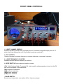
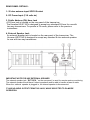
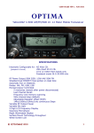
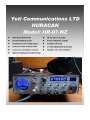
Downloaded from www.cbradio.nl
CONGRATULATIONS on your purchase of a HURACAN HR-07-NZ 10meter
amateur radio. Your HURACAN HR-07-NZ transceiver radio is designed to
provide trouble-free service and state of the art, high performance SSB
communications.
This radio has been designed with the SSB eenthusiast in mind
incorporating new circuitry for increased SSB stability and improved SSB
audio.
To ensure proper performance, please read this manual thoroughly.
BEFORE YOU OPERATE THE HR-07-NZ
10 METER AMATEUR RADIO
In most countries a special licence is required to transmit on Amateur
radio frequencies. Please ensure you have the required licence to
operate this radio in the country you are using it.
YeticomNZ is not responsible for any liabilities resulting from improper or
unlicenced use of this equipment.
SPECIFICATIONS:
HR-07-NZ
10 METER HF MOBILE TRANSCEIVER
GENERAL
Frequency Range:
Frequency Control:
Frequency Tolerance:
Frequency Stability:
Operating Temp.
Microphone:
Input Voltage:
Current Drain:
Tx :
Rx :
Size:
Weight:
Antenna Connector:
Meter:
10m Band
28.000-29.995 MHz.
Export
25.000-29.995 export (5 bands 1mhz ea)
NZ CB
26.330-26.770 40ch CB Band with channel readout
Phase Lock Loop (PLL) synthesizer.
0.005%
0.001%
Range: -22 F to +122 F.
Plug-in dynamic; with push-to-talk switch and coiled cord.
13.8V DC nominal, 15.9V max 11.7V min.
AM full mod., 2.2A.
Squelched, 0.3A.
Maximum AF output, 0.7A
2-3/8 (H) x 7-7/8 (W) x 9-1/4 (D)
5 lbs.
UHF, SO239
Illuminated ; indicates relative output power, received signal strength
TRANSMITTER
Power Output (Max):
AM
FM
SSB
10w Carrier/50W PEP
50W
50W PEP
Modulation: AM = Class B Amplitude.
FM = 2.5Khz @ 20mV 1Khz Audio in Spurious Emission -60dB
AF Modulation Response AM / FM 450 – 2500 Hz
RECEIVER
Circuit Type : Dual-Conversion Superheterodyne
Intermediate Frequencies :
1st IF / SSB IF ........ 10.695 MHz
2nd IF ........................ 455 kHz
Sensitivity :
SSB ...................................................0.25 μV at 10 dB S + N/N
AM ....................................................1.0 μV at 10 dB S + N/N
FM.....................................................0.3 μV at 12 dB SINAD
Selectivity :
SSB .................................4.2 kHz (-6 dB) / 8.5 kHz (-60 dB)
AM / FM ........................................... 6.0 kHz (-6 dB) / 18 kHz (-60 dB)
IF Frequencies AM/FM 1st 10.695Mhz, 2nd 455Khz.SSB 10.695Mhz
Adjacent Channel Rejection : Better than 70 dB
IF Rejection : Better than 80 dB for all frequencies
Automatic Gain Control (AGC): Less than 10dB change in audio output for inputs From 10 V to
50,000 V.
Squelch/ RF Gain Controls: 0.5 V=0dB Center Ref. adjustable +3dB to –40dB From threshold at
rated sensitivity adjustable at Full mute 25 V at Max Gain, 1mV at Min. Gain.
ANL+NB: RF Type ANL @3dB + NB @12dB
Clarifier Range : Fine: 1.5Khz Rx/Tx
Audio Output: 4W Max., 3W @10% THD with 8 Ohms Load.
Audio Response: 450-2500Hz.
External PA Output: 4W at 8 Ohms, disables internal speaker while plugged-in.
INSTALLATION
1. Contents
Unpack and inspect your Huracan HR-07-NZ
for missing or damaged components. Your
Huracan HR-07-NZ includes the following
items:
Quantity
Description
1
Huracan HR-07-NZ Transceiver
1
Dynamic Microphone
1
DC Power Cord with Inline Fuse
1
Mounting Bracket with Hardware
1
Mic Hanger with Hardware Set
1
Operating Manual
2. Microphone Hanger
The microphone hanger may be attached to
the side of the transceiver, or any other
convenient location. Locate the mounting holes
on the side of the transceiver. Use the provided
screws to attach the microphone hanger
either vertically or horizontally to the side of
the transceiver.
3. Mounting
When attaching the Huracan HR-07-NZ
mounting bracket to the vehicle, choose a
location that will provide easy access to all front
panel controls and air circulation to the rear
panel. When selecting a mounting location,
make sure that there is ample space behind
the unit for the cables. Do not pinch, or bend
sharply, the power or antenna cables. Do not
install the Huracan HR-07-NZ in any
compartment that restricts airflow to the air
vents under the transceiver or blocks the heat
sink and do not install in a location that
interferes with the safe operation of the vehicle.
Attach the mounting bracket to the vehicle first
then mount the Huracan HR-07-NZ to the
bracket. If the rear panel is not accessible you
may want to attach the power and antenna
cable prior to mounting.
4. Electrical Connections
The Huracan HR-07-NZ is designed to work
on any 12 - 14.1 volt DC, negative ground,
source. The condition of a vehicle’s electrical
system can affect operation. A low battery,
worn generator/alternator, or poor voltage
regulator will seriously impair the performance
of the transceiver. Any of the above conditions
could result in a high level of receiver noise
generation or a substantial loss of the
transmitter’s RF output.
Make sure that all of these components of your
vehicle’s electrical system are in good condition
prior to installing the transceiver.
CAUTION! VOLTAGE EXCEEDING 15 VDC
WILL DAMAGE THE RADIO. MEASURE
VOLTAGE AT BATTERY TERMINALS, WITH
VEHICLE RUNNING, PRIOR TO
INSTALLATION!
Before making any electrical connections
make sure the volume (VOL) control is in the
“OFF” position. Connect the positive (+) red
wire of the DC power cord to a positive 13.8
volt source at the vehicle fuse block. If
connecting to the fuse block, it is recommended
that a switched power source is used so that
the power to the transceiver is is connected
when the vehicle is off. This will eliminate the
possibility of the transceiver draining the
vehicle’s battery. Connect the negative (-)
black wire to a metal part of the vehicle’s frame,
or chassis ground. Make sure that this is a
good ground connection.The Huracan HR-07NZ power cord may also be connected directly
to the battery. Connecting directly to the battery
has several benefits, the first of which is to
maximize RF output. Secondly, the battery is a
very large capacitor and will help eliminate
certain types of ambient and vehicle noise. If
connecting directly to the vehicle’s battery,
additional power cable may be required.On
runs of 8 feet or less use 14-gauge stranded
wire. Use 12-gauge wire on longer runs.
5. Antenna Connection:
The transceiver will operate using any
standard 50-ohm ground-plane, vertical,
mobile whip, long wire or similar antenna. The
antenna should be rated at 50 watts PEP
minimum. A standard SO-239 type antenna
connector is located on the rear panel of the
Huracan HR-07-NZ. Connection is made using
a PL-259 and high-grade coaxial cable
(RG213, RG58A/U or Mini RG-8 is
recommended). A ground-plane antenna
provides
greater
coverage
and
is
recommended for fixed station-to-mobile
operation. For point-to-point fixed station
operation, a directional beam antenna
operates at greater distances even under
adverse conditions. A non-directional antenna
should be used in a mobile installation; a
vertical whip is best suited for this purpose. The
base loaded whip antenna normally provides
effective communications. For greater range
and more reliable operation, a full quarter wave
whip may be used. Either of these antennas
uses the metal vehicle body as a ground
plane.Once the antenna is mounted on the
vehicle, route the coaxial cable so that it is not
next to any power cables or vehicle cables.
Connect the PL-259 to the antenna connector
on the rear panel of the Huracan HR-07-NZ.
Make sure that the cable does not interfere with
the safe operation of the vehicle.
treadings should be below 1.5 to 1 across the
entire operating band. If at the lower or upper
end of the transceiver operating frequency, the
VSWR measures more than 1.5 to 1, it is
recommended that the antenna be retuned
before operating on those frequencies.If you
are experiencing unusual VSWR readings
check for the following possible problems:)
1: Make sure that the antenna is installed
properly and grounded.
2) Check all coaxial cable and connectors for
defects and poor routing.
3) If testing a vehicle installation, make sure
that all vehicle doors are closed when
testing.
4) Do not test near or around large metal
objects or buildings.
6. VSWR:(Requires external s.w.r meter)
Before use, it is important to determine the
antenna system’s VSWR (voltage standing
wave ratio). You will need a high quality SWR
bridge (meter) to accurately tune your
antenna system. First, make sure the SWR
bridge is in good working order and is
calibrated. To ensure your radio is performing
properly the VSWR should never exceed 1.5 to
1. Never transmit on any antenna system
where the VSWR exceeds 1.8 to 1.This will
stress the output stage and could destroy the
RF mosfets; this type of misuse and failure is
not covered under warranty. Measure the
VSWR at the center of the operating band.
Tune the antenna (according to the antenna
manufacturer’s tuning instructions) so that the
VSWR is as close to 1 to 1 at the center of the
operating band. Next, measure the VSWR at
the lowest and highest
frequency of the
transceiver. If the antenna has a wide enough
frequency range and band-pass, he VSWR
WARNING
CONTINUOUS OPERATION OF THIS
TRANSMITTER WITH GREATER THAN 4:1
VSWR ANTENNA MISMATCH MAY RESULT
IN RF AMPLIFIER DAMAGE.
TUNING THE ANTENNA FOR OPTIMUM SWR
Since there is a such a wide vanity of base and
mobile antennas, this section will strictly
concern itself to the various types of mobile
adjustable antennas. Because the antenna
length is directly related to the channel
frequency, it must be tuned to resonate
optimally all Frequencies of the transceiver.
28.000mhz requires a longer antenna than
29.700mhz, because it is lower in frequency.
Due to the various methods of adjusting
antennas for proper SWR we have chosen what
we think is the optimum method:
A. Antenna with adjustment screws (set screws)
1. Start with the antenna extended and tighten
the set screw tightly enough so that the
antenna can be lightly tapped with your finger
for easy adjustment.
2. Set your transceiver to a mid band frequency.
Press PTT (push-to-talk) switch, and tap the
antenna shorter. The SWR meter will show a
lower reading each time the antenna is tapped.
By continuing to shorten the antenna you will
notice the SWR reading will reach a lowest
point and than start to rising again, this means
the optimum tuning being pressed for center
operating frequency of your transceiver.
B. Antennas which must be cut to length
1. Follow the same procedure as above, but
adjust the length by cutting in 1/8 inch
increments until a good match is obtained.
2. Be very careful not to cut too much at one
time, as once it is cut, it can no longer be
lengthened.
3. The whip is easily cut by filing a notch all the
way around and breaking the piece off with
pliers.
TIPS for Antenna Adjustment
IF YOU ARE HAVING DIFFICULTIES IN
ADJUSTING YOUR ANTENNA
CHECK THE FOLLOWING:
A. All doors of the vehicle must be closed when
adjusting the antenna.
B. Make sure the antenna base is grounded.
C. Check your coaxial cable routing to make
sure it is not pinched when routed into the car.
D. Try a different location on your car, keeping
in mind the radiation pattern you wish.
E. Is the antenna perfectly vertical ?
F. Try a different location in your neighborhood.
Stay away from large metal objects when
adjusting, such as metal telephone or light
poles, and fences, etc.
ANTENNA
A vertically polarized, quarter-wavelength whip
antenna provides the most reliable operation
and greatest range. Shorter, loaded-type whip
antennas are more attractive, compact and
adequate for applications where the maximum
possible distance is not required.Also, the
loaded whips do not present the problems of
height imposed by a full quarter wavelength
whip. Mobile whip antennas utilize the metal
body of the vehicle as a ground plane. When
mounted at a corner of the vehicle they are
slightly directional, in the direction of the body
of the vehicle. For all practical purpose,
however, the radiation pattern is nondirectional. The slight directional characteristic
will be observed only at extreme distances. A
standard antenna connector (type SO 239) is
provided on the transceiver for easy connection
to the standard PL-259 cable termination.If the
transceiver is not mounted on a metal surface,
it is necessary to run a separate ground wire
from the unit to a good metal electrical ground
in the vehicle. When installed in a boat, the
transceiver will not operate at maximum
efficiency without a ground plate, unless the
vessel has a steel hull. Before installing the
ransceiver in a boat, consult your dealer for
information regarding an adequate grounding
system and prevention of electrolysis between
fittings in the hull and water.
7. Ignition Noise
In certain vehicle installations, electrical noise
or interference may be present in the
receive audio of the transceiver.
Typically the vehicle’s ignition system or more
specifically the alternator generates this
noise. The Huracan HR-07-NZ is equipped with
a noise blanker circuit that is designed
to reduce, and in many instances eliminate,
this electrical noise. In extreme cases, the
noise blanker may not eliminate all the electrical
noise. In such cases, an alternator/ ignition
noise filter can be used Use of a mobile
receiver at low signal levels is limited by the
presence of electrical noise.The primary source
of noise in automobile installations is from the
generator and ignition system in the vehicle.
Under most operating conditions, when signal
level is adequate, the background noise does
not present a serious problem. Even though the
transceiver has ANL / NB controls, in some
vehicles the ignition interference may be high
enough to significantly effect the performance
of the radio communications. The electrical
noise may come from several sources. Many
possibilities exist and variations between
vehicles require different solutions to reduce the
noise level.
NOTE :
WHEN EXTREMELY LOW LEVEL SIGNALS
ARE BEING RECEIVED, THE TRANSCEIVER
MAY BE OPERATED WITH VEHICLE ENGINE
TURN OFF. THE UNIT REQUIRES VERY
LITTLE CURRENT AND THEREFORE WILL
NOT SIGNIFICANTLY DISCHARGE THE
VEHICLE BATTERY.ON
FRONT PANEL CONTROLS:
1. 2-DIGIT CHANNEL DISPLAY
Displays operating channel does not display when in Free-band mode.Will display when in 10
meter mode (see options list) or N.Z auto select mode (see control #7).
2. VFO CONTROL:
Rotate clockwise to increase frequency or counter-clockwise to decrease frequency.
.
3. 6-DIGIT FREQUENCY COUNTER
Displays Receive/Transmit frequency in real time
4. MODE SWITCH: Selects desired operation modes.
(PA): Public Address Mode. To operate PA, insert a public address speaker or horn into the PA
jack on the rear panel of the transceiver.
(FM) Frequency modulation
(AM) Amitutre modulation
(USB) Upper sideband
(LSB) Lower sideband
5:BAND SWITCH:
Selects band of operation see options list for frequency ranges
6: S/RF Meter:
The meter indicates relative receive signal strength, RF output power, The meter features blue
backlighting on receive and red backlighting on transmit. The meter features 2 scales Rx signal in
60dB max., and Tx max. 50W, the lower scale indicates relative signal strength (S units) for
received transmissions. The top scale indicates the RF output power of the Huracan HR-07-NZ.
O
7. Free-band/NZ40 Selector Auto Selector:
When in the “Freeband” position the transceiver will work as per the options chart depending on
the option the transceiver is setup for. In N.Z mode the channel display lights up and the radio will
default to channel 35 (26.720mhz) which is the New Zealand LSB (lower sideband “call channel”
8. CLARIFIER:
Transmit and receive tuning range /+1.5khz
9. MONI: All Mode Talk-back Monitor:
All Mode Talk Back. is an independent talk back monitor. The AMT functions in all modes and
allows the operator to monitor the transmitted audio of the Huracan HR-07-NZ.To increase the
volume of the talk back rotate the control clockwise. To decrease rotate counter-clockwise. To turn
off the talk back rotate the control completely counter-clockwise.
10. Echo On/Off-Delay:
Echo Delay. Varies the amount of delay, or duration of the echo repetition. Rotate clockwise to
increase the amount of delay and counter-clockwise to decrease.
11. R.F Power am/fm only:
Variable RF Output Power. The transmitted power of the Huracan HR-07-NZ may be varied from 0
to 50 watts peak in Am/Fm modes. Rotate clockwise to increase RF output power. Rotate
counter-clockwise to decrease RF output power .Variable 1-10 watts carrier Am Mode /1-50 watts
carrier Fm mode.
12. Microphone Gain.
Microphone Gain. Increases or decreases the energy developed in the microphone amplifier
circuit.The gain increases as the control is rotated clockwise.
13.Sq/Rf Gain control:
Squelch and RF Gain combinded. Used to eliminate background or “white” noise when monitoring
strong signals. To properly adjust the squelch circuit,Start rotating the control slowly counter
clockwise until the received white noise disappears. Adjusts the receiver sensitivity to
both signals and background noise. This affects the distance at which a signal can be detected.
Turning the control counterclockwise reduces the receiver sensitivity. This is particularly useful in
areas where large volumes of traffic (signals) are present
14.ON/OFF:
Turns the radio on and off. Rotate the control clockwise until it clicks to turn off.
VOL:
Volume. Adjusts the AF gain, or volume of the receive audio. Turn clockwise to
increase and counter-clockwise to decrease.
15. Rodger Beep:
Activates the end of transmission, or roger beep, tone. When activated a 1 kHz tone will
automatically transmit upon release of PTT switch .This notifies contacts that your transmission
has ended and you are ready to receive their signal
16. Front Mounted Microphone input:
Microphone wiring is as follows: Pin 1 : Ground
Pin 2 : Microphone Audio
Pin 3 : Transmit
Pin 4 : Receive
17. Guard-Band Filter ©: (narrow/wide).I.F Filter an Switchable (narrow/standard) 6 pole I.F Filter
with buffer .in normal use the filter switch would be in the out position (standard receive
bandwidth) under bad band conditions or splatter from a couple of channels away from a over
powered station or close station this can be put in to the depressed position (narrow) to help
remove or suppress the offending signal.
18. NB-ANL SWITCH:
Noise Blanker and Automatic Noise Limiter. In the NB position, only the noise blanker is ON. In
the ANL position the automatic noise limiter are ON. The noise blanker circuit eliminates pulse
type interference usually associated with automotive ignition systems
.
19.DIM /OFF/BRITE: The 3 stage dimmer control allows you to select the proper
illumination level for both the S/RF meter and blue LED displays. In the OFF position disables the
frequency counter
REAR PANEL DETAILS:
1: 50 ohm antenna input SO239 Socket:
2: DC Power Input (13.8 volts dc)
3. Public Address (PA) Horn Jack
A PA horn jack is located on the rear panel of the transceiver.
The Huracan HR-07-NZ is designed to accept any standard PA horn for use with
two-way transceivers. To operate in PA mode, please refer to the previous
instructions.
4. External Speaker Jack
An external speaker jack is located on the rear panel of the transceiver. The
Huracan HR-07-NZ is designed to accept any standard 8 ohm external speaker
for use with two way transceivers.
IMPORTANT NOTE FOR USE EXTERNAL SPEAKERR1
The external speaker jack “ EXT. SPK. ” on the rear panel, is used for remote receiver monitoring.
The external speaker should have 8 ohms impedance and be able to handle at least 4 watts.
When the external speaker is plugged in, the internal speaker is disconnected.
IT HAS NO AUDIO OUTPUT FROM THIS JACK, WHILE SELECTED TO P.A.MODE
OPERATION.
USING YOUR RADIO FOR THE FIRST TIME :
PROCEDURE TO RECEIVE
1. Turn unit on by tuning ON / OFF VOLUME control clockwise.
2. Set the VOLUME for a comfortable listening level.
3. Set the MODE switch to the desire mode.
4. Listen to the background noise from the speaker. Turn the SQ/RFG Gain control slowly counter
clockwise until the noise JUST disappears (no signal should be present). Leave the control at
this setting. The SQL/RF Gain. Is now properly adjusted. The receiver will remain quiet until a
signal is actually received Do not advance the control too far, or some of the weaker
signals will not be heard.
5. Set the VFO selector and band switchs to the desired frequency.
6. Set the SQ/RF gain control fully clockwise for maximum RF gain if required (defeats squelch
In this setting.)
7. Select the desired frequency of transmission.
8. Set the MIC. GAIN control fully clockwise.
9. Set R.F power control to power level required.
10. If the frequency is clear, depress the PTT switch on the mic., and speak in a normal voice.
PRESS-TO-TALK MICROPHONE
Press the switch and the transmitter is activated, the receiver and transmitter are controlled by the
PTT switch on the microphone., release switch to receive. When transmitting, hold the
microphone two inches from the mouth and speak clearly in a normal “ voice
ALTERANIVE MICROPHONES:
The Radio come complete with low impedance (500 ohms) dynamic microphone.
For best results, the user should select a low-impedance dynamic type microphone or a
transistorized microphone. Transistorized type microphones have a low output impedance
characteristic.The microphones must be provided with a four-lead cable. The audio conductor and
its shielded lead comprise two of the leads. The fourth lead is for receive control, and the third is
for transmit control. The microphone should provide the functions shown in FIG. 1 of the
microphone wiring schematic.If the microphone to be used is provided with per-cut leads, they
must be received as follows.
Cut leads so that they extend 7/16” beyond the plastic insulating jacket of the microphone cable.
All leads should be cut to the same length. Strip the ends of each wire 1/8” and tin the exposed
wire.Before beginning the actual wiring read carefully, the circuit and wiring information provided
with the microphone you select. Use the minimum head required in soldering the connections.
Keep the exposed wire lengths to a minimum to avoid shorting when the microphone plug is
reassembled.
MICROPHONE PLUG REASSEMBLING:
1. Remove the retaining screw.
2. Unscrew the housing from the pin receptacle body.
3. Loosen the two cable clamp retainer screws.
4. Feed the microphone cable though the housing, knurled ring and washer
shown in FIG. 3.
5. The wires must now be soldered to the pins as indicated in the FIG. 1, wiring tables. If a vise
or clamping tool is available, it should be used to hold the pin receptacle body during the
soldering operation, so that both hands are free to perform the soldering. If a vise or clamping
tool is not available, the pin receptacle body can beheld in a stationary position by inserting it
into the microphone jack of the front panel. The numbers of the pins of the microphone plug
are shown in FIG. 2, as viewed from the back of the plug. Before soldering the wire to the
pins, per-tin the wire receptacle of each pin of the plug.
Be sure that the housing and the knurled ring of FIG. 3 are pushed back onto the
microphone cable before starting to solder. If the washer is not captive to the pin
receptacle body, make sure that it is placed on the threaded portion of the pin receptacle
body before soldering.If the microphone jack is used to hold the pin receptacle during the
soldering operation,best results are obtained when the connections to pins 1 and 3 are made first
and then the connections to pins 2, 4 and 5. Use a minimum amount of solder and be careful to
prevent excessive solder accumulation on pins, which could cause a short between the pin
and the microphone plug housing.
6. When all soldering connections to the pins of the microphone plug are complete, push
the knurled ring and the housing forward and screw the housing onto the threaded
portion of the pin receptacle body. Note the location of the screw clearance hole in the
plug housing with respect to the threaded hole in the pin receptacle body.When the
housing is completely threaded into the pin receptacle body, a final fraction of a turn
either clockwise or counter clockwise may be required to align the screw hole with the
threaded hole in the pin receptacle body. When these are aligned, the retaining screw
is then screwed into the place to secure the housing to the pin receptacle body
7. The two cable clamp retainer screws should now be tightened to secure the housing to the
microphone cord. If the cutting directions have been carefully followed, the cable clamp
should secure to the insulating jacket of the microphone cable.Upon completion of the
microphone plug wiring, connect and secure the microphone plug in the transceiver.
Receiving SSB Signals
There are four types of signals presently used for communications in an Amateur band: AM, FM,
USB and LSB. When the MODE switch on your unit is placed in the AM position, only standard
double sideband and in FM position, only frequency deviation, full carrier signals will be detected.
An SSB signal may be recognized while in the AM or FM mode by its characteristic “ Donald Duck
“ sound and the inability of the AM or FM detector to produce an intelligible output, the USB and
LSB modes will detect upper sideband and lower sideband respectively , and standard AM signals
SSB reception differs from standard AM reception in that SSB receiver does not require a carrier
or opposite sideband to produce an intelligible signal. A signal-sideband transmitted signal
consists only of the upper or the lower sideband and no carrier is transmitted. The elimination of
the carrier from the AM signal helps to eliminate the biggest cause of whistles and tones heard on
channels which make even moderately strong AM signals unreadable.The reduction in channel
space required also helps in the receiver because only half of the noise and interference can be
received with 100% of the SSB signal.
An SSB signal may be received only when the listening receiver is functioning in the same mode.
In other words, an upper sideband signal (USB) may be made intelligible only if the receiver is
functioning in the USB position. If the lower sideband (LSB) signal is heard when the receiver is in
the USB mode, no amount of tuning will make the signal intelligible.
The reason for this may be understood if you consider that when modulation is applied to the
transmitter’s microphone in the USB mode, the transmitter’s output frequency is increased
whereas in the LSB mode the transmitter’s output frequency is decreased. The result in listening
the receiver is that when the MODE switch is in the proper position either USB or LSB.
A true reproduction of signal tone of modulation will result, and if the tone is increased in
frequency such as a low pitched whistle will caused a high-pitched whistle you will hear the
increase in the output tone of the receiver. If the incorrect mode is selected, an increase in tone of
a whistle applied to the transmitter will cause a decrease in the resultant tone from the receiver.
Thus when a voice is used in place of a whistle or tone, in the proper listening mode the voice will
be received correctly whereas in the incorrect mode, the voice will be translated backwards and
cannot be made intelligible by the voice lock control. When listening to an AM transmission, a
correct sideband is heard in either mode since both upper and lower sideband is received.
Once the desired SSB mode has been selected, frequency adjustment may be necessary in order
to make the incoming signal intelligible, the CLARIFIER control allows the operator to vary
frequency above and below the exact-center frequency of the received signal. If the sound of the
incoming signal is high or low pitched, adjust the operation of the CLARIFIER. Consider it as
performing the same function as a phonograph speed control. When the speed is set to high,
voices will be high-pitched and if set too low, voices will be low-pitched. Also, there is only one
correct speed that will make a particular record produce the same sound that was recorded. If the
record is played on a turntable that rotated in the wrong direction (opposite sideband) no amount
of speed control (CLARIFIER) will produce an intelligible sound.
An AM signal received while listening in one of the SSB modes will produce a steady tone (carrier)
in addition to the intelligence, unless the SSB receiver tuned to exactly the same frequency by the
Clarifier control. For simplicity it is recommended that the AM modes be used to listen to AM
signals.
OPTIONS LIST
Introduction:
The HURACAN HR-07-NZ is programmed for the 10 Meter Amateur Band out of the box, and
covers a range of 28.000 -29.695 MHz in 5 khz steps standard.
The frequency range can be extended for Export Use in 6 Band segments OF 1MHZ each
containing 200 Channels (200 X 5KHZ STEPS= 1MHZ).
10 Meter Only Mode:
The default setting from the factory covers 8 bands between 28.000 MHz – 29.695 MHz. The
jumper setting for this is JP1, JP2, JP3 ,JP4 = all jumpers OFF (N.Z 40 channel auto select
mode can be used in this mode)
Free-band Mode:
This mode is pre-set to 6 Bands (1MHZ each 200x 5khz steps )between 25.000 MHz – 30.995
MHz. The jumper setting for this mode is JP1 = ON , JP2= OFF,JP3 = ON JP4 = OFF.
(N.Z 40 channel auto select mode can be used in this mode)
Programming Notes:
* Replace the Metal Cover on the Channel Board after programming to reduce receiver
noise.