1
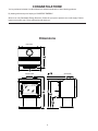
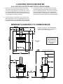
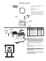
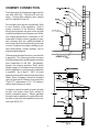
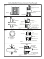
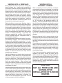
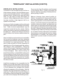
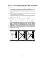
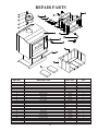
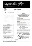
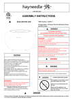
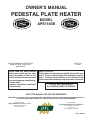
OWNER'S MANUAL
PEDESTAL PLATE HEATER
STATES STO
VE
ITED
N
U
USSC
MODEL
APS1100B
COMPANY
STATES STO
VE
ITED
N
U
USSC
COMPANY
US ENVIRONMENTAL PROTECTION
AGENCY PHASE II CERTIFIED
WOODSTOVE
Please read this entire manual
before you install and use your
new room heater. Failure to follow these instructions may result
in property damage, bodily injury,
or even death.
Improper installation could void
your warranty.
TESTED TO
UL 1482
SAFETY NOTICE:
If this heater is not properly installed, a house fire may
result. For your safety, follow the installation instructions. Contract local building or fire officials about
restrictions and installation requirements in your area.
DO NOT USE THIS HEATER
IN A MOBILE HOME OR TRAILER
SAVE THIS MANUAL FOR FUTURE REFERENCE
THIS MANUAL WILL HELP YOU TO OBTAIN EFFICIENT, DEPENDABLE SERVICE FROM THE HEATER, AND ENABLE YOU
TO ORDER REPAIR PARTS CORRECTLY. KEEP IN A SAFE PLACE FOR FUTURE REFERENCE.
Manufactured By:
Distributed By:
Qingdao Hichanse Group Co., LTD
UNITED STATES STOVE COMPANY
168 Wenhua Road, Jimo
Quingdao, China
227 Industrial Park Road
P.O. Box 151
South Pittsburg, TN 37380
Pt. No.: 851684
1
CONGRATULATIONS!
You've purchased a heater from North America's oldest manufacturer of wood burning products.
By heating with wood you're helping to CONSERVE ENERGY!
Wood is our only Renewable Energy Resource. Please do your part to preserve our wood supply. Plant at
least one tree each year. Future generations will thank you.
Dimensions
(TOP VIEW)
(FRONT VIEW)
(SIDE VIEW)
2
SAFETY RULES
SAFETY NOTICE: If this heater is not properly installed a house fire may result. For your safety, follow the
installation directions. Contact local building or fire officials about restrictions and installation inspection
requirements in your area.
Read these rules and the instructions carefully.
1.
Check with local codes. The installation comply with their
rulings. Observe closely the clearances to combustibles.
2.
Do not install this heater in a mobile home or trailer.
3.
DO NOT connect a wood burning heater to an aluminum
Type B gas vent. This is not safe and is prohibited by the
National Fire Protection Association Code and Canadian
Standards.
13. Disposal of Ashes- Place ashes in a metal container with
a tight fitting lid. Keep the closed container on a noncombustible floor or on the ground, well away from all
combustible materials. Keep the ashes in the closed
container until all cinders have thoroughly cooled. The
ashes may be buried in the ground or picked up by a
refuse collector.
14. Keep the firebox section free of excess ashes.
4.
Always connect this heater to a chimney and vent to the
outside. Never vent to another room or inside a building.
15. Observe clearances to combustible materials specified
in this manual to avoid a fire hazard.
5.
This heater must be connected to a chimney complying
with the requirements for HT type chimneys in the standard for chimneys (6" dia. single wall, 24 Ga. min., black
or blued steel chimney connector pipe.), a Factory-Built,
Residential Type and Building Heating Appliance, UL
103 or a code-approved masonry chimney with a flue
liner.
16. CARING FOR PAINTED PARTS- This heater has a painted
jacket, which is durable but it will not stand rough handling or abuse. When installing your heater, use care in
handling. Clean with soap and warm water when heater
is not hot. DO NOT use any acids or scouring soap, as
these wear and dull the finish. PAINT DISCOLORATION
WILL OCCUR IF THE HEATER IS OVERFIRED. FOLLOW OPERATING INSTRUCTIONS CAREFULLY.
6.
Be sure that your chimney is safely constructed and in
good repair. Have the chimney inspected by the Fire
Department or a qualified inspector. Your insurance company may be able to recommend a qualified inspector.
7.
Make sure the chimney is high enough to give a good draft.
8.
Inspect chimney connector and chimney twice monthly
during the heating season for any deposit of creosote or
soot which must be removed (see Chimney Maintenance
in this manual).
9.
DO NOT BE ALARMED IF HEATER SMOKES UPON
INITIAL FIRING. The special paint used on this heater
must be cured during initial firing. This smoking will occur
only on initial firing.
10. CAST IRON PARTS MUST BE "SEASONED" TO AVOID
CRACKING. BUILD ONLY SMALL FIRES DURING THE
FIRST FEW DAYS OF USE.
11. To prevent injury, do not allow anyone to use this heater
who is unfamiliar with the correct operation of the heater.
17. The firebox walls in this heater may become slightly
distorted over a period of use. The slight distortion does
not affect the operation of the unit.
18. CAUTION: HOT WHILE IN OPERATION. KEEP CHILDREN, CLOTHING, AND FURNITURE AWAY. CONTACT MAY CAUSE SKIN BURNS.
19. CAUTION: DO NOT CONNECT TO ANY AIR DISTRIBUTION OR DUCT SYSTEM.
20. CAUTION: STORE SOLID WOOD FUEL A SAFE DISTANCE AWAY. DO NOT STORE SOLID WOOD FUEL
WITHIN HEATER INSTALLATION CLEARANCES OR
WITHIN THE SPACE REQUIRED FOR ASH REMOVAL.
21. DO NOT USE A GRATE OR ELEVATE THE FIRE.
22. WE RECOMMEND THAT SMOKE DETECTORS BE INSTALLED IN YOUR HOME.
23. DO NOT CONNECT THIS UNIT TO A CHIMNEY SERVING ANOTHER APPLIANCE.
12. For additional information on using your Room Heater
safely, obtain a copy of the National Fire Protection
Association (NFPA) publication "Chimneys, Fireplaces,
and Solid Fuel Burning Appliances" NFPA No. 211(USA).
CAUTION! Do not touch the metal or glass surfaces of the heater until it has thoroughly cooled.
3
LOCATING THE ROOM HEATER
AS A LOCATION IS SELECTED, KEEP THE FOLLOWING IN MIND:
1. Keep the chimney connection as short as possible.
The heater must have its own chimney flue. Do not
connect any other appliance to the same flue. If there
is no chimney where you wish to place the heater, you
can use a UL 103 HT, Solid Fuel, Factory Built Chimney
or a code-approved masonry chimney.
3. Check figures below. You should have at least the
clearances shown from the heater and the connector
pipe to combustible surfaces. If you have a solid brick
or stone wall behind your heater, you can place the
heater as close as you wish to the wall. If the wall is only
faced with brick or stone, treat it as a combustible wall.
2. Place the heater on solid masonry or solid concrete.
When the heater is used on a combustible floor, use a
floor protector of a non-combustible material extending
beneath the heater and must measure as figure below.
MINIMUM CLEARANCE TO COMBUSTIBLES
MINIMUM CLEARANCES FOR CORNER INSTALLATION IS 18 INCHES FROM THE CORNERS OF
THE HEATER TO THE NEAREST WALL
CAUTION
KEEP FURNISHINGS
AND OTHER COMBUSTIBLE MATERIALS
AWAY FROM THE
HEATER
TOP VIEW
Fig. 2
*Not Tested, NFPA Minimum
FRONT VIEW
Fig. 3
SIDE VIEW
Fig. 4
4
APS1100 Assembly
This heater comes equipped with a cast-iron
flue collar to mount as shown below:
Flue Collar
5/16-18 x 1-1/2" Bolts (3 req.)
Weld Tab (3 req.)
Gasket
Peel off tape from the back of the gasket and
attach the gasket to the rope groove in the flue
collar. Mount flue collar to the top of the heater
using the (3) 5/16-18 x 1-1/2" Bolts, Washers,
and the (3) Weld tabs provided in the parts
bag.
Flue Collar
Fig. 5
Side view of flue collar
mount to heater top
KEY DESCRIPTION
1
2
3
4
5
6
N/S
N/S
Blower Motor
Blower Housing Front
Blower Housing Back
Power Supply Cord
Rheostat w/Nut and Knob
Strain Relief Bushing
10AB x 3/8 Hex Zinc Screw
#12 x 3/4 Teks Screw
PART NO. QTY.
80442
25090B
25089B
80232
80090
80109
83222
C23799
1
1
1
1
1
1
8
4
ASSEMBLY INSTRUCTIONS
Step 1.
THE BLOWER ASSEMBLY MUST BE DISCONNECTED FROM THE SOURCE OF ELECTRICAL SUPPLY BEFORE ATTEMPTING THE INSTALLATION.
With pliers, cut the 4 tabs and remove panel on the
back of the stove. Note: Discard the panel.
Step 2.
Fix the assembly to the back of the stove with the
four screws provided.
THE BLOWER ASSEMBLY IS INTENDED FOR USE
ONLY WITH A STOVE THAT IS MARKED TO INDICATE SUCH USE.
(Stove Back)
DO NOT ROUTE THE SUPPLY CORD NEAR OR
ACROSS HOT SURFACES!
Fig. 6
5
CHIMNEY CONNECTION
Two basic types of chimneys are approved for
use with solid fuel. Factory-built and masonry. Factory-built chimney must comply
with UL standard in the US.
Do not expect your stove to create draft. Draft
is not a function of the appliance. Draft is
purely a function of the chimney. Modern
stoves and furnaces are much more air-tight
and efficient than those of the past, and, therefore, require greater draft. A minimum of .05"
measured in water column (gauges to measure chimney draft are readily available at
stove shops and are economical to purchase
or rent) is required for proper drafting to prevent back-puffing, smoke spillage, and to
maximize performance.
Chimneys perform two functions - one of which
is apparent: The chimney provides a means
for exhausting smoke and flue gases resulting
from combustion of the fuel. Secondarily,
though, the chimney provides "Draft" which
allows oxygen to be continuously introduced
into the appliance, so that proper combustion
is possible. As of April 1, 1987, all wood
heaters and furnaces manufactured by United
States Stove Company should be installed
using a factory-built chimney that meets the
"Type HT" requirement of UL 103 (when a
factory-built chimney is used).
Fig. 7
A chimney connector shall not pass through
an attic, roof space, closet, floor, ceiling, or
similar concealed space. Where passage
through a wall or partition of combustible construction is desired, the installation must conform with NFPA 211.
Fig. 8
6
Combustible Wall Chimney Connector Pass-Throughs
PART A
FIGURE 9
MINIMUM CHIMNEY CLEARANCE TO BRICK
AND COMBUSTIBLES IS 2 IN.
CHIMNEY FLUE
MINIMUM CLEARANCES 12 IN. OF BRICK
ALL AROUND
CHIMNEY CONNECTOR TO HEATER
MINIMUM 12 IN.
TO COMBUSTIBLES
FIRE CLAY LINER
(5/8" MIN. WALL THICKNESS)
MASONRY CHIMNEY
CONSTRUCTED TO NFPA 211
MIN. 3-1/2" THICK BRICK MASONRY WALL
NONSOLUBLE
REFACTORY
CEMENT
AIR SPACE
FACTORY-BUILT
CHIMNEY LENGTH
CHIMNEY FLUE
MINIMUM CHIMNEY CLEARANCES FROM MASONRY TO
SHEET STEEL SUPPORTS AND COMBUSTIBLES 2 IN.
PART B
FIGURE 9
CHIMNEY LENGTH
FLUSH WITH INSIDE
OF FLUE
AIR SPACE
9 IN. MINIMUM
MINIMUM CLEARANCE
9 IN. ALL AROUND
CHIMNEY CONNECTOR
TO HEATER
USE CHIMNEY MFRS. PARTS TO
ATTACH CONNECTOR SECURELY
SOLID INSULATED, LISTED
FACTORY-BUILT CHIMNEY LENGTH
MASONRY CHIMNEY CONSTRUCTED
TO NFPA 211
PART C
FIGURE 9
SHEET STEEL SUPPORTS
(24 GAUGE MIN. THICKNESS)
MINIMUM CHIMNEY CLEARANCES FROM MASONRY TO
SHEET STEEL SUPPORTS AND COMBUSTIBLES 2 IN.
24 GAUGE
VENTILATED THIMBLE WITH
TWO 1 INCH AIR CHANNELS
CHIMNEY FLUE
CHIMNEY THIMBLE
TWO VENTILATED AIR
CHANNELS EACH 1 INCH.
CONSTRUCTED OF
SHEET STEEL.
MASONRY CHIMNEY CONSTRUCTED
TO NFPA 211
CHIMNEY CONNECTOR
TO HEATER
MINIMUM 6 IN. GLASS
FIBER INSULATION ALL AROUND
SHEET STEEL SUPPORTS
(24 GAUGE MIN. THICKNESS)
MINIMUM CHIMNEY CLEARANCES FROM MASONRY TO
SHEET STEEL SUPPORTS AND COMBUSTIBLES 2 IN.
PART D
FIGURE 9
SHEET STEEL SUPPORTS
MINIMUM CLEARANCE
2 IN. ALL AROUND
CHIMNEY SECTION
1 IN. AIR SPACE TO
CHIMNEY LENGTH
CHIMNEY THIMBLE
CHIMNEY FLUE
CHIMNEY
CONNECTOR
AIR SPACE
2 IN.
MASONRY CHIMNEY CONSTRUCTED
TO NFPA 211
7
CHIMNEY CONNECTOR
TO HEATER
SOLID INSULATED, LISTED
FACTORY-BUILT CHIMNEY
LENGTH (12 IN. LONG MIN.)
SHEET STEEL SUPPORTS
(24 GAUGE MIN. THICKNESS)
Combustible Wall Chimney Connector Pass-Throughs
Method A. 12" Clearance to Combustible Wall Member
Use a minimum 3-1/2" thick brick masonry wall framed into the combustible wall. A fireclay liner (ASTM C315 or equivalent) having a 5/8" minimum wall thickness must be used and it must be at least 12" away from any material that could
catch fire. The inside diameter of the fireclay liner shall be sized for the proper snug fit of a 6" diameter chimney connector
pipe. The fireclay liner shall run from the outer surface of the brick wall to, but not beyond, the inner surface of the chimney
flue and shall be firmly cemented in place.
Method B. 9" Clearance to Combustible Wall Member
Use a solid insulated listed factory-built chimney length having an inside diameter of 6" and having 1" or more of solid
insulation. There must be at least a 9" air space between the outer wall of the chimney length and any combustible
materials. The inner end of the chimney length shall be flush with the inside of the masonry chimney flue shall be sealed
to the flue and to the brick masonry penetration with nonwater-soluble refractory cement. Sheet steel supports which are
at least 24 gauge(0.024") in thickness shall be securely fastened to wall surfaces on all sides. Fasteners between
supports and the chimney length shall not penetrate the chimney liner.
Method C. 6" Clearance to Combustible Wall Member
Use a 10" diameter ventilated thimble made of at least 24 gauge(0.024") steel having two 1" air channels. The ventilated
thimble must be separated from combustible materials by a minimum of 6" glass fiber insulation. The opening in the
combustible wall shall be covered and the thimble supported with sheet steel supports which are at least 24 gauge (0.024")
in thickness. The sheet steel supports shall be securely fastened to wall surfaces on all sides and shall be sized to fit and
hold the chimney section. Fasteners used to secure chimney sections shall not penetrate chimney flue liner.
Method D. 2" Clearance to Combustible Wall Member
Use an 8" inside diameter solid insulated listed factory-built chimney length which has 1" or more of solid insulation. The
minimum length of this chimney section shall be 12" and will serve as a pass-through for the 6" diameter chimney
connector. There must be at least a 12" air space between the outer wall of the chimney section and any combustible
materials. The chimney section shall be concentric with and spaced 1" away from the chimney connector by means of
sheet steel support plates on both ends of the chimney section. The opening in the combustible wall shall be covered and
the chimney section supported on both sides with sheet steel supports which are at least 24 gauge (0.024") in thickness.
The sheet steel supports shall be securely fastened to wall surfaces on all sides and shall be sized to fit and hold the
chimney section. Fasteners used to secure chimney sections shall not penetrate chimney flue liner.
A listed factory-built wall pass-through system may be purchased and installed according to the instructions packaged with
it to provide a safe method of passing the chimney connector through a combustible wall for connection to a masonry
chimney.
Notes:
1. Connectors to a masonry chimney, expecting method B, shall extend in one continous section through the wall passthrough system and the chimney wall, to but not past the inner flue liner face.
2. A chimney connector shall not pass through an attic or roof space, closet or silmilar concealed space, or a floor, or
ceiling
8
VENTING INTO A FIREPLACE
VENTING INTO A
MASONRY CHIMNEY
Many people may wish to convert an existing fireplace to heater use. Usually, safe connection of
stovepipe to a masonry chimney requires more effort
than connection to a prefabricated chimney. The
fireplace must be tightly closed and sealed at the
damper in the flue. Good sealants are high-temperature caulking, ceramic wool, and furnace cement.
Always remember to inspect the masonry chimney
and fireplace. If necessary, clean the flue and smoke
shelf before beginning your installation. Install the
heater into the fireplace so that the system can be
dismantled for cleaning and inspection.
When considering a masonry chimney, round tiles
are preferable to square or rectangular, as round tiles
have much better airflow characteristics and are far
easier to clean. Unfortunately, most North American
chimneys use square or rectangular tile liners that are
really designed for open fireplaces, not stoves or
furnaces. Of most importance, second only to overall
chimney height, is the diameter of the flue liner itself.
In most instances, it should be sized to the appliance;
i.e., 6" flue outlet on the appliance requires a 6"
chimney. The inner diameter should never be less
than the flue-outlet diameter and should never be
greater than 50% larger than the appliance flue outlet.
For example, do not expect a wood or coal burning
stove or furnace to function properly if installed into a
chimney with a flue greater than 50% more than the
appliance outlet - - such as a 6" flue outlet requires a
6" diameter for optimum drafting, but can function well
with an 8", but becomes borderline beyond an 8"
diameter.
Before deciding to convert your fireplace, keep in
mind that some fireplaces and existing chimneys are
unsafe. They must be structurally sound, and the flue
liner must be in good condition. Do not use a chimney
if it is unlined (should have a fire clay tile liner to protect
brickwork). Have it relined professionally. Clearances to combustibles are explained in the previous
section on masonry chimneys. If you have any
questions regarding the condition of the chimney,
consult a qualified engineer, competent mason, or
knowledgeable inspector.
Masonry chimneys built of concrete blocks with or
without flue liners do not meet modern building codes.
A solid fuel appliance must not be joined to a chimney
flue which is connected to another appliance burning
other fuels.
Many prefabricated fireplaces fall into the "zero-clearance fireplace" category. This is a factory-built metal
fireplace with multilayered construction. It is designed to provide enough insulation and/or air cooling
so that the base, back and sides can be safely placed
in direct contact with combustible floors and walls.
Although many prefabricated fireplaces have been
tested by nationally recognized organizations for use
as fireplaces, they have not been tested to accept
heaters. In fact, their use as such may void the
manufacturer's warranty.
If your chimney has a typically oversized flue liner of,
say 8 x 12 inches, or greater, or if it is unlined, it will be
necessary for you to reline the chimney, using any of
the modern approved and economical methods such
as stainless steel, castable refractory, or properly
sized fireclay linings.
If you have any questions regarding venting your
appliance, feel free to contact the factory at the
address and phone number on this Owner's Manual.
You may also contact NFPA (National Fire Protection
Association) and request NFPA Standard 211 (1984
Edition-US). Another helpful publication is NFPA
Standard 908(US). Specify 1984 Edition of either of
the above US publications.
Steel-lined fireplaces, on the other hand, can be used
with heaters. These units use a 1/4-inch firebox liner
and an air chamber in connection with 8 inches of
masonry to meet code. They contain all the essential
parts of a fireplace, firebox, damper, throat, smoke
shelf, and smoke chamber. Many of them look
exactly like a masonry fireplace and must be checked
closely for above requirements before installing a
wood heater into them.
CAUTION:
NOT ALL FIREPLACES ARE
SUITABLE FOR
INSTALLATION OF A WOOD
HEATER.
Another method frequently used by some people is to
vent the heater directly into the fireplace. This does
not meet code since the heater is being vented into
another appliance - the fireplace. This method should
not be attempted because combustion products will
deposit and build up in the firebox or fireplace. Be
certain not to install a hazard in your house. You will
void your warranty with this installation.
9
"FIREPLACE" INSTALLATION (CONT'D)
Do not use the Type B installation (not illustrated
in this manual), that is, venting up through the
fireplace opening, regardless of whether the fireplace opening is closed.
FIREPLACE INSTALLATION
Connection of the stovepipe directly into the existing masonry chimney over the fireplace opening is a more desirable method. This installation
performs better, yielding more heat and better
draft; it is also easy to clean and inspect for
creosote. Before beginning this type of installation plan carefully; a high degree of skill is required to insure safety.
Masonry chimneys have several positive attributes: If properly built, they are quite durable,
and most homeowners consider them more attractive perhaps than an unenclosed factory built
chimney. And, if the chimney is located within the
confines of the house (that is, not attached to an
exterior wall), its mass alone will store heat longer
and continue to release the heat long after the fire
has died. Masonry chimneys have many disadvantages though. Masonry chimneys constructed
on an exterior wall are exposed to cold outdoor
temperatures, promoting greater heat loss, higher
accumulations of creosote, and reduced draft
which leads to poorer heater or furnace performance.
An entry port for the stovepipe must be cut through
the chimney with minimum damage to the fireclay
liner. Some involved measurements may be
required to locate the flue liner exactly. Before
cutting, take time to mark the size and position of
the entry port. Position the entry port so that at
least 8 inches of the flue liner remains below the
port.
Keep in mind that wood mantels and combustible
trim around the fireplace must have adequate
clearances from the heater and stovepipe or must
be protected in an approved manner. Also, be
sure to leave at least an 18 inch clearance between the top of the stovepipe and the combustible ceiling or other combustibles. Placing the
center of the entry port 2 feet below the ceiling will
insure proper clearance for 6-inch, 8-inch, and
10-inch stovepipes. Next, install a fireclay (at
least 5/8 inch thick) or metal thimble, being sure
that the thimble is flush with the inner flue lining,
secure the thimble in place with refractory mortar.
The thimble should be surrounded on all sides
with 8 inches of brickwork (solid masonry units) or
24 inches of stone.
Install the stovepipe as far as possible into the
thimble, but not past the inside of the flue lining.
There should be a small airspace (approximately
1/2 inch) between the stovepipe and thimble,
allowing for expansion of the stovepipe. Seal this
airspace with high-temperature caulking or ceramic wool. Finally, be sure to wire the damper in
the fireplace closed and apply the same sealant
you used at the stovepipe and thimble junction.
Fig. 10
10
RULES FOR CONNECTOR PIPE INSTALLATION
1.
2.
3.
4.
5.
6.
7.
8.
Crimped end of the pipe must be installed toward the heater. The
pipe should slide inside the flue collar. The pipe should be firmly
attached to the flue collar with 3 screws and sealed with furnace
cement.
Slope any horizontal pipe upward toward the chimney at least 1/4
" inch for each foot of horizontal run.
You must have at least 18" inches clearance between any horizontal piping and the ceiling.
The pipe cannot extend into the chimney flue.(Fig. 8)
Seal each connector pipe joint with furnace cement. Also seal the
pipe at the chimney.
Use 3 sheet metal screws at each joint to make the piping rigid.
It is recommended that no more than two (2) 90 degree bends be
used in the stove pipe installation as more than two (2) may
decrease the amount of draw and possibly cause smoke spillage.
The chimney connector must not pass through an attic or roof
space, closet, or any concealed space, or floor, ceiling, wall or
combustible construction.
Fig. 11
11
OPERATING INSTRUCTIONS
WARNING!
NEVER STORE FLAMMABLE LIQUIDS,
ESPECIALLY GASOLINE. IN THE
VICINITY OF THE HEATER.
Wood Fuel
Use Hardwood that has been split and air-dried to obtain
maximum burning efficiency.
CAUTION!
OVERFIRING THE APPLIANCE MAY
CAUSE A HOUSE FIRE. IF A UNIT OR
CHIMNEY CONNECTOR GLOWS, YOU
ARE OVERFIRING.
Lighting Instructions
1.
Open door and place paper and kindling in the firebox.
2.
Light the fire and close the door until the kindling is
burning.
3.
Open the door and add fuel as desired.
CAUTION!
NEVER USE GASOLINE, GASOLINE-TYPE
LANTERN FUEL, KEROSENE, CHARCOAL
LIGHTER FLUID, OR SIMILAR
LIQUIDS TO START OR "FRESHEN UP" A
FIRE IN THIS HEATER.
KEEP ALL SUCH LIQUIDS WELL AWAY FROM
THE HEATER WHILE IT IS IN USE.
Extended Operation
1.
Fuel should be added in small amounts to give more
complete combustion and uniform room temperature.
2.
Empty the ashes regularly. Do not allow ashes to
build up. Dispose of hot ashes properly in a metal
container with a lid.
WARNING!
OPERATE ONLY WITH THE FEED DOOR FULLY
CLOSED.
SERVICE HINTS
Do not expect a heater to draw. It is the chimney that creates
the draft. Smoke spillage into the house or excessive buildup
of water or creosote in the chimney are warnings that the
chimney is not functioning properly. Correct problem before
using heater. Possible causes are:
1.
The connector pipe may be pushed into the chimney too
far, stopping the draft.
2.
Do not connect two heaters into the same chimney flue.
3.
The chimney used for a heater must not be used to
ventilate the cellar or basement. If there is a cleanout
opening at the base of the chimney, It must be closed
tightly.
4.
If the chimney is operating too cool, water will condense
in the chimney and run back into the stove. Creosote
formation will be rapid and may block the chimney.
Operate the heater at a high enough fire to keep the
chimney warm preventing this condensation.
5.
If the fire burns well but sometimes smokes or burns
slowly, it may be caused by the chimney top being lower
than another part of the house or a nearby tree. The wind
blowing over a house or tree, falls on top of the chimney
like water over a dam, beating down the smoke. The top
of the chimney should be at least 3 feet above the roof
and be at least to 2 feet higher than any point of the roof
within 10 feet (Fig. 6).
CHIMNEY MAINTENANCE
Creosote - Formation and Need for Removal
If creosote has accumulated, it should be removed. Failure
to remove creosote may cause a house fire. Creosote may
be removed by using a chimney brush or other commonly
available materials.
When wood is burned slowly, it produces tar and other
organic vapors, which combine with expelled moisture to
form creosote. The creosote vapors condense in the relatively cool chimney flue of a slow burning fire. As a result,
creosote residue accumulates on the flue lining. When ignited this creosote makes an extremely hot fire.
Chimney fires burn very hot. If the chimney connector should
glow red, immediately call the fire department, then reduce
the fire by closing the air damper and pour a large quantity
of coarse salt, baking soda or cool ashes on top of the fire in
the firebox. CAUTION: A chimney fire may cause ignition of
wall studs or rafters which you thought were a safe distance
from the chimney. If you have a chimney fire, have your
chimney inspected by a qualified person before using again.
The chimney connector and chimney should be inspected at
least twice monthly during the heating season to determine
if a creosote buildup has occurred.
12
REPAIR PARTS
KEY NO.
DESCRIPTION
PART NO.
QTY.
1
2
3
4
5
6
7
8
9
10
11
12
13
14
15
16
17
18
19
20
21
22
23
24
25
26
Hex Head Bolt
3/8 ID Washer
Flue Collar
Flue Collar Gasket
Weld Tab
Firebox Weldment
Top Plate Trim
Brass Handle
Hearth Trim
Keps Nus
Door Latch Spacer
Door Latch
Door Latch Bushing
10-24 x 3/8 PH Bolt
Bottom Bracket
Door Glass
Glass Gasket
Door Gasket
Feed Door
Door Handle
Brass Handle
Top Bracket
Door Hinge Pin
Firebrick (4.5 x 9 x 1.25)
Firebrick (4.5 x 7.38 x 1.25)
Firebrick (5.19 x 9.25 x 1.25)
83432
83045A
40292
88042
83431
Af0040A
AF0027
Af0019
AF0028
83274
AF0034
AF0007
AF0035
83202
AF0024
AF0038
88087
88066
AF0036
AF0020
89574
AF0025
AF0023
89066
AF0021
AF0055
3
3
1
13
1
1
1
1
1
1
1
1
1
4
1
1
1
1
1
1
1
1
2
12
4
2
13
BRICK PLACEMENT - (TOP INSIDE VIEW OF FIREBOX)
WIRING DIAGRAM FOR BLOWER ASSEMBLY
CAUTION!
THE BLOWER ASSEMBLY
MUST BE DISCONNECTED FROM THE
SOURCE OF ELECTRICAL
SUPPLY BEFORE ATTEMPTING ANY MAINTENANCE.
WARNING!
DO NOT ROUTE THE
SUPPLY CORD
NEAR OR ACROSS
HOT SURFACES!
14
ASHES - REMOVAL AND DISPOSAL
Ashes should not be allowed to accumulate inside the heater to the point that they obstruct airflow through the
burning wood. If ashes obstruct the airflow, poor burning of the wood is likely.
When removing ashes from the heater, wear noncombustible gloves to protect your hands from hot surfaces.
Rake ashes using an ash shovel and dump ashes into a safe, noncombustible container.
ASHES SHOULD BE PLACED IN A METAL CONTAINER WITH A TIGHT FITTING LID. THE CLOSED CONTAINER OF ASHES SHOULD BE PLACED ON A NONCOMBUSTIBLE FLOOR OR ON THE GROUND,
WELL AWAY FROM ALL COMBUSTIBLE MATERIALS, PENDING FINAL DISPOSAL. IF THE ASHES ARE
DISPOSED OF BY BURIAL IN SOIL OR OTHERWISE LOCALLY DISPERSED, THEY SHOULD BE RETAINED IN THE CLOSED CONTAINER UNTIL ALL CINDERS HAVE THOROUGHLY COOLED.
Ashes should never be placed in a wooden, cardboard, or plastic container, nor in a paper or plastic bag, no
matter how long the fire has been out. Coals have been known to stay hot for several days when embedded
in ashes.
Glass Replacement Instructions for APS1100B
7. Use only the glass specified for this unit.
Contact your local dealer or customer service for replacement glass.
8. Warning: Do not slam door or strike glass.
Slamming door or striking glass may cause
glass to break.
9. Caution: Do not build fire directly on glass.
10. Warning: Do not use abrasive cleaners.
Abrasive cleaners may damage the glass.
11. Warning: Do not use substitute materials.
1. Be sure heater has cooled before begining.
2. Remove 4, 10-24 x 3/8 screws and glass
retainers with screw driver.
3. Remove damaged glass.
4. To reinstall glass, follow steps 1-2 in reverse order. Be sure to replace the gasket
on the glass.
5. Caution: Do not operate with broken glass.
6. When removing broken glass, wear thick
gloves, and safety glasses. Keep children
away. Discard broken glass.
15
HOW TO ORDER REPAIR PARTS
THIS MANUAL WILL HELP YOU OBTAIN EFFICIENT, DEPENDABLE SERVICE FROM THE
HEATER, AND ENABLE YOU TO ORDER REPAIR PARTS CORRECTLY.
KEEP IN A SAFE PLACE FOR FUTURE REFERENCE.
WHEN WRITING, ALWAYS GIVE THE FULL MODEL NUMBER WHICH IS ON THE NAMEPLATE ATTACHED TO THE BACK OF THE HEATER.
WHEN ORDERING REPAIR PARTS, ALWAYS GIVE THE
FOLLOWING INFORMATION AS SHOWN IN THIS LIST:
1. The PART NUMBER
2. The PART DESCRIPTION
3. The MODEL NUMBER: APS1100B
4. The SERIAL NUMBER: ____________________
UNITED STATES STOVE COMPANY
227 Industrial Park Road
P.O. Box 151
South Pittsburg, TN 37380
1-800-750-2723
www.USSTOVE.com
16