1
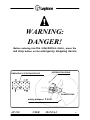
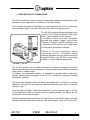
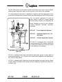
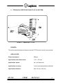
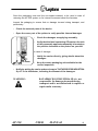
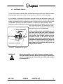
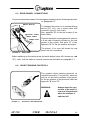
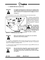
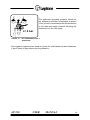
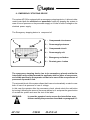
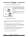
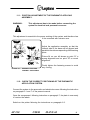
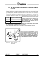
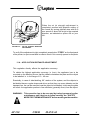
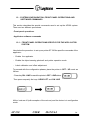
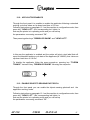
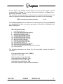
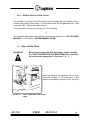
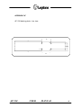
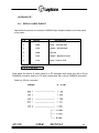
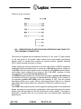
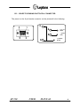
AP 230
No - contact
printer/applicator
system
USER MANUAL
UV504UGB
DATAPROCESS EUROPE S.p.A.
20082 Binasco (MI)
Viale dell'Artigianato, 19
Tel. (+39) 02900221
Fax.(+39) 0290091353
AP 230
USER
MANUAL
1
INDEX:
WARNING
page.
3
WARNING DANGER
page.
4
RESIDUAL RISK OF THE SYSTEM
page.
5
1 - DESCRIPTION OF THE MACHINE
2 - TECHNICAL SPECIFICATION OF AP 230 SYSTEM
3 - UNPACKING AND INSPECTION
page. 6
page. 8
page. 10
4 - STORAGE AND TRANSPORT
4.1 - TRANSPORT
4.2 - WORKING PLACE
page. 12
page. 12
page. 13
5 - MOUNTING THE SINGLE COMPONENTS OF THE APPLICATOR
5.1 - MOUNTING THE BACKING PLATE
5.2 - MOUNTING THE ROLL HOLDER UNIT
5.3 - MOUNTING THE PNEUMATIC APPLICATION UNIT
5.4 - LOCATION OF THE FASTENING POINTS OF THE SYSTEM
page.
page.
page.
page.
page.
14
14
16
18
19
6 - ELECTRICAL AND PNEUMATIC CONNECTIONS
6.1 - ELECTRICAL CONNECTIONS
6.2 - NOTICE FOR CUSTOMERS IN THE UNITED KINGDOM
6.3 - REAR PANNEL, CONNECTIONS
6.4 - OBJECT SENSING PHOTOCELL
page.
page.
page.
page.
page.
20
20
21
22
22
7 - COMPRESSED AIR CONNECTION
page. 23
8 - EMERGENCY STOPPING DEVICE
8.1 - INSTALLATION AND MAINTENANCE PROCEDURE
page. 25
page. 26
9 - LABEL AND FOIL LOADING PROCEDURE
9.1 - INKED RIBBON LOADING
page. 28
page. 29
10 - ADJUSTING THE FLANGES ON THE ROLL HOLDER
page. 30
11 - PNEUMATIC UNIT ADJUSTMENT
11.1 - POSITION ADJUSTMENT OF THE PNEUMATIC APPLYING GROUP
11.2 - CHECK THE CORRECT POSITIONING OF THE PNEUMATIC APPLICATION SYSTEM
11.3 - SETTING THE DIRECTION AND AIR JET STRENGHT FROM THE NOZZLES
11.4 - APPLICATION DISTANCE ADJUSTMENT
page.
page.
page.
page.
page.
30
31
31
34
35
12 - SYSTEM CONFIGURATION; FRONT PANEL OPERATIONS AND SOFTWARE COMMANDS
12.1 - FRONT PANEL OPERATIONS SPECIFIC FOR THE APPLICATOR SYSTEM
12.2 - APPLICATOR ENABLES
12.3 - ENABLE OBJECT SENSING PHOTOCELL
12.4 - LABEL CALIBRATION AND OFFSET ADJUSTMENT
12.5 - SOFTWARE COMMANDS OF THE APPLICATOR
12.6 - CONFIGURATION OF SYSTEM OPERATION MODE
12.7 - APPLICATOR CONFIGURATION
12.8 - LABEL OFFSET
12.9 - SINGLE APPLICATION CYCLE
page.
page.
page.
page.
page.
page.
page.
page.
page.
page.
36
36
37
37
39
39
39
40
40
42
13 - FINAL OPERATIONS
page. 42
14 - MAINTENANCE
page. 43
15 - APPLICATOR TROUBLE SHOOTING
page. 43
APPENDICE
APPENDICE
APPENDICE
APPENDICE
APPENDICE
AP 230
"A"
"B"
"B.1"
"B.2"
"B.3"
page.
page.
page.
page.
page.
USER
MANUAL
45
46
46
47
49
2
WARNING:
This user manual constitutes an integrated part of the AP 230
system, it contains how-to-use instructions for professional
and non-professional users. Such instructions inform and
advise the users on the correct use of the system and at the
same time inform and advise on the residual risk due to the
improper use of the system. It is therefore compulsory to have
copy of this manual near the working place.
AP 230
USER
MANUAL
3
WARNING:
DANGER!
Before entering into the interdiction zone, press the
red stop button on the emergency stopping device
EMERGENCY STOPPING DEVICE
INTERDICTION ZONE
DANGER ZONE
safety distance
AP 230
USER
1.4 m
MANUAL
4
RESIDUAL RISKS OF THE SYSTEM
WARNING:
The system, during its working cycle, presents some mechanical hazards, that can be the origin of injuries due to
mechanical actions of the machine parts. Do not access
into the interdiction zone before carefully following the
"SAFETY MODE FOR THE MAINTENANCE" procedure as
described at points 1 and 2 of paragraph 8.1.
Such mechanical hazards can be evaluated as
follows:
- Crushing hazard
- Cutting/Severing hazard
With reference to the above mentioned hazards,
it is compulsory to follow the here below safety
NO measure:
-
It is necessary to exclude the interdiction zone all around the application system with deterrent and/or hamper device fixed on the floor, such as for example yellow/black stakes joint together with a protection chain of the same colour
having a floor height of 100 cms. minimum and safety distance of 1.4 m. from
the applicator plate. Warning boards indicated the interdiction zone and kind
of hazard will be hung on the chain that exclude the interdiction zone.
-
The emergency stopping device, placed outside the interdiction zone, is a safety
device that activates automatically by stopping the system in case of loss of
tension or loss of pressure on the pneumatic supply, blocking the unexpected/
unintended start up of the system when the supply sources are returned. Re-start
will be possible only by actioning the buttons on the emergency stopping device
by the operator.
-
All personell, that can occasionally have access to the interdiction zone, have
to be instructed on the residual risk and on the no-entrance on the interdiction
zone. It is particularly reccommended to instruct the personnel on the residual
risks and on the prohibitions, and to follow carefully the "SAFETY MODE FOR
THE MAINTENANCE" procedure before accessing into the interdiction zone.
AP 230
USER
MANUAL
5
1 - DESCRIPTION OF THE MACHINE
The AP 230 system is a device used for overprinting of adhesive labels and for their
immediate air-jet application on stable or on moving objects.
Once inserted into either a packaging or product transport line, the AP system can
print and apply labels in a wide range with bar-codes and diverse texts.
The AP 230 contains the same printing group
of the ST 230 Thermal Transfer Printer, from
which it has inherited all the features.
The system is able to print texts, bar-codes,
symbols and graphic images using Direct
Thermal or Thermal Transfer technology, with
a resolution of 6-8 dots/mm, on a wide range
of both paper and plastic materials.
Thanks to its solid construction, ribbon
economizer device, reloadable ribbon
cartridge, printhead energy control circuit and
extreme flexibility, the AP 230 is particularly
suitable to most industrial applications.
PICTURE 1 - AP 230
The AP 230 systems can be easily connected to Personal Computers and other
electronic equipment via serial interface in order to create and print labels containing
either fixed or variable data.
In addition, an optoisolated interface is available for synchronization and alarm
signals, allowing easy integration of the AP 230 system into complex industrial
automation systems.
The pneumatic assembly allows the label to be applied with “no contact” on moving
objects by using the air-jet technique, therefore eliminating the need to stop the
transport line.
Once the label has been printed and detached from the support paper, it is held
on the application plate by suction and then pushed towards the object by the
movement of the transport piston.
When the passing object is detected, the label is blown onto the the object with high
precision and the piston then returns to the initial postion, ready for a new cycle.
AP 230
USER
MANUAL
6
The AP 230 system can be easily installed according to the user’s various needs,
allowing label application either on the top and on the side of the package.
The high speed and precision of application, together with the indipendence from
speed of the transport line, are some of the many advantages of the AP 230 systems.
The "no-contact" application is ideal for
either fragile or difficult to handle objects
that may have surfaces not completely flat.
Much flexibility is given by the different
systems "AP230F", "AP230L", "AP230V"
available:
AP 230 F
Front Applicator System
AP 230 L
Applicator System for 170
mm labels
AP 230 V
Variable Applicator System
AP 230 F is equipped with a particular
rotating label plate of 90° degree, and allows
to easily apply labels also on the front/back
of the objects to be labelled.
PICTURE 2 - AP 230 SYSTEM ON
LABEL LINE.
AP 230 L, equipped with a large dimensions label plate, allows to apply labels of
dimentions maximum 115 x 170 mm, and is particularly suitable for the applications
that require large labels.
AP 230 V, equipped with a particular device that regulats the piston course, allows
to apply labels on different size objects without modifying its positioning referred to
transport line.
AP 230
USER
MANUAL
7
2 - TECHNICAL SPECIFICATIONS OF AP 230 SYSTEM
PICTURE 3 - DIMENTIONS OF AP 230.
PRINTER
The printer specifications are the same as the ST 230 printer (see its user manual).
APPLICATOR
Piston movement:
200mm
Application plate dimensions:
115 x 120 mm
Application speed:
up to 45 label/min.
Application accuracy:
1 mm in nominal operation conditions
Application distance:
from 10 mm to 40 mm
AP 230
USER
MANUAL
8
INTERFACES
Type:
Serial RS 232C Asynchronous
Buffer:
64 kbytes
Protocol:
Xon/Xoff or CTS/RTS
Data transmission speed:
300 to 38.400 baud
Alarm and synchronizations:
Input and output optoisolated signals.
POWER SUPPLY
Electric:
220V ±10% (optional 110, 120, 240V)
50/60 Hz; 200 Va.
Pneumatic:
6 bar min., 200 lt/min., filtered dry air.
SIZE AND WEIGHT
Width:
285 mm
Depth:
900 mm
Height:
510 mm
Piston movement:
200 mm
Weight:
28 Kg
ENVIROMENTAL CONDITION
Temperature:
from 5° to 40° C
Humidity:
20% to 90% non condensig.
AP 230
USER
MANUAL
9
3 - UNPACKING AND INSPECTION
Open the packaging and check the following standard components:
1)
2)
3)
4)
5)
6)
7)
8)
9)
AP 230 user manual
ST 230 user manual
Object sensing photocell (with
reflector)
Tool kit
Roll holder unit including flanges
Power cable
ST 230 printing mechanism
AP 230 pneumatic application unit
Backing plate.
The picture 4 on your left shows the main
components and their position in the
package.
PICTURE 4 - AP 230 PACKAGE.
Open the second package and check that contains the "EMERGENCY STOPPING
DEVICE", composed of a plastics box equipped with supply plugs, automatic pipes
for compressed-air supply tube, and a stop red button and a green re-start button.
WARNING:
AP 230
It is recommended to check if the package contains the
Emergency Stopping Device and the User Manual, as they
are part of the applying system for safety purposes.
USER
MANUAL
10
Save the packaging units and the non-impact material, to be used in case of
returning the AP 230 system or for internal movement about the factories.
Inspect the pakaging to ensure that no damage incurred during transport, and
particularly:
-
Check the external parts of the device.
-
Open the cover port of the printer to verify possible internal damages.
-
Check the damages on applying assembly.
-
Verify that the label containing CE mark on the side
of the pneumatic applicator assembly is located on
the position indicated on the picture on your left.
In case of damage:
CE MARK
-
-
Notify the carrier directly, giving details about the
damages.
-
Keep the whole packaging unit available for the
carrier inspection.
Notify by writing the carrier and send copy to "DATAPROCESS INDUSTRIA
S.p.A" or its distributor, indicating the amount of the damages.
WARNING:
AP 230
DATAPROCESS INDUSTRIA SPA is not
responsable for dameges incurred during
transport and is not authorized to replace or
repair under warranty.
USER
MANUAL
11
4 - STORAGE AND TRANSPORT
In case of non immediate use the AP 230 should be stored with its original package.
The enviromental conditions are the following:
-
Temperature:
from 5° to 35° C
-
Humidity:
20% to 90% non condensing.
4.1 - TRANSPORT
In order to provide a safety moving of the AP 230 follow the under below instructions:
WARNING:
Before entering into interdiction zone created all around
the AP 230 system, follow carefully all the indication listed
"SAFETY MODE FOR THE MAINTENANCE" procedure
described at point 1 and 2 of the paragraph 8.1.
a) Transport inside of the factories
-
Disconnect the AP 230 applicator system from the power supply (see paragraph
6.1)
Disconnect the compressed-air supply tube (see paragraph 7)
Disconnect the data cable from the serial port mounted on the rear panel of the
printer (see paragraph 6.2)
Disconnect the cable of the object sensing photocell by the proper plug on the
rear panel of the printer (see paragraph 6.2)
Keep off the applicator from applying line.
b) Transport outside the factory
Disconnect the applicator by the power and data supply, as indicated on point “a”,
dismantling the parts comprising the applicator, following instructions on paragraph
5 point “5.1 - 5.2 - 5-3” and store into the standard original package as indicated on
the picture 4 of page. 10.
AP 230
USER
MANUAL
12
4.2 - WORKING PLACE
The AP 230 system can be easily installed according to the user’s various needs,
allowing label application either on the top and on the side of the package.
It is necessary to exclude the interdiction zone all around the application system with
deterrent and/or hamper device fixed on the floor, such as for example yellow/black
stakes joint together with a protection chain of the same colour having a floor height
of 100 cms. minimum and safety distance of 1.4 m. from the applicator plate.
Warning boards indicating the interdiction zone and kind of hazard will be hung on
the chain that exclude the interdiction zone.
The chain will be compulsory closed during
the working cycle of the applicator.
SAFETY DISTANCE
In the proximity of the interdiction zone, in
any case outside the area, will be installed
the emergency stopping device located in
easy access and visible position by the
operator so that to be sure of the nonpresence of personnel exposed to risk. It is
advisable to install the emergency stopping
device in a range from the applicator so
that cables and connecting pipes are not
longer than 5 meters.
INTERDICTION ZONE
PICTURE 5 - WORKING PLACE AP 230 .
WARNING:
AP 230
During the working cycle of the system, nobody should
enter the interdiction zone. Before accessing the interdiction
zone it is compulsory to follow all the procedures described
at paragraph 8.1.
USER
MANUAL
13
5 - MOUNTING THE SINGLE COMPONENTS OF THE APPLICATOR
The assembly of the single components of the applicator are divided in the following
four phases:
5.1 - Mounting the backing plate.
5.3 - Mounting the pneumatic application unit.
5.2 - Mounting the roll holder unit.
AP 230
USER
5.4 - Identification of the system fastening points on the backing plate .
MANUAL
14
5.1 - MOUNTING THE BACKING PLATE
Unpack the printer and place it upside down on a table top.
Remove the two rubber feet, as indicated on
picture 6 on your left, unlocking the two screws
that fasten them at the base of the printer.
PICTURE 6 - RUBBER FEET
Unscrew the M 5 x 20 mm screw located in the
middle of the base of the printer, as indicated
on picture 7 on your left.
PICTURE 7 - MIDDLE M 5 SCREW.
Place the backing plate on the printer so that the plate holes will match the printer
holes.
AP 230
USER
MANUAL
15
Take off from the tool kit the two M 4 x 20 mm
screws, insert and fasten the two screws on
the two pre-drilled holes on the backing plate.
Insert and fasten the screw M 5 x 20 mm in the
hole located in the middle of the backing plate,
as indicated on picture 8 on your left.
Now completely tighten all the backing
fastening screws to avoid them loosening when
working, which would impair the proper
operation of the system.
PICTURE 8 - FASTENING SCREWS.
5.2 - MOUNTING THE ROLL HOLDER UNIT
Place the printer on its side, unpack the roll
holder unit and take off from the tool kit the two
screws M 5 x 16 mm.
Place the roll holder unit on the back part of the
backing plate, so that the external roll holder is
in front of the proper slot created on the rear
panel to let labels to pass.
Insert and fasten the two screws of the roll
holder unit on the two pre-drilled holes on the
backing plate, as indicated on picture 9 on
your left.
PICTURE 9 - ROLL HOLDER UNIT
FASTENING.
Now completely tighten the screws to avoid any movement of the roll holder unit
under the weight of the label rolls.
AP 230
USER
MANUAL
16
Place the printer in its upright position and
insert the first flange with the smooth side
inward the printer, as indicated on picture 10
on your left.
The flange adjustment on the roll holder unit is
described at paragraph 9.
PICTURE 10 - PAPER GUIDE FLANGE
If the machine mainly works with a 90° rotation,
also mount the plexiglass disk (available as
optional), on the flange and fasten it with the
two countersunk screws supplied with the
disk, as indicated on picture 10 on your left.
PICTURE 11 - PLEXIGLASS DISK
AP 230
USER
MANUAL
17
5.3 - MOUNTING THE PNEUMATIC APPLICATION UNIT
Unpack the application unit and take from the tool kit the two screws M 8 x 30 mm
complete with their washers. Place the
application unit in its upright position, on the
front of the printer, hold it by one hand while
with the other one insert the two screws in the
two pre-drilled holes created on the base of
the application unit so that they will match the
holes on the backing plate, and fasten, without
locking, as indicated on picture 12 on your left.
NOTE:
To adjust and center the applicator
both on side and lenghtwise respective to the printer see the paragraph 11 concerning the pneumatic assembly adjustment.
PICTURE 12 - MOUNTING THE PNEUMATIC
APPLICATION UNIT.
WARNING:
NO
During this phase do
not connect the cable
of the applicator to the
plug (4 pin, male), located on the printer front
panel, as indicated on
picture 13 on your left.
PICTURE 13 - APPLICATION CABLE
AP 230
USER
MANUAL
18
5.4 - LOCATING OF THE FASTENING POINTS OF THE SYSTEM
The backing plate is equipped with a certain number of holes to be used to fasten
the system to the application line or to mount,
if desired, a backing flange for a support
column, as indicated on picture 14 on your left.
On the backing plate has been pre-drilled a
serie of eight holes : 4 M 10 and 4 M 8.
PICTURE 14 - AP 230 ON COLUMN
WARNING:
In case of the above mentioned instructions are not carrefully
followed you can incurr residual mechanical hazards
due to a unlocking of the screws causing a loss of stability
of the system and its collapse.
On appendix "A" a dimentioned drawing of the backing plate is reported.
AP 230
USER
MANUAL
19
6 - ELECTRICAL AND PNEUMATIC CONNECTIONS
6.1 - ELECTRICAL CONNECTION
AP 230 system has to be connected to the power supply , through the emergency
stopping device that has to be
fixed outside the interdiction
zone following the instructions
below:
3
4
1
2
1Prepare a feeding cable
with an adequate section not
less than 3 x 1,5 mm, where
from applicator side will be
mounted the dedicated female
connector that will be inserted
into the plug on the rear panel of
the printer.
2On the opposite pole of
the cable, mount the dedicated
spindle and insert it into the supply plug with protected contacts that is mounted on the emergency stopping device.
PICTURE 15 - POWER SUPPLY
3Insert the female connector of the supply cable into the proper plug mounted
on the emergency stopping device.
4Connect the spindle of the power cord to an appropriate socket outlets with
following voltages:
220 VAC ± 10% 50/60 Hz
110 VAC ± 10% 50/60 Hz (as per require)
240 VAC ± 10% 50/60 Hz (as per require)
WARNING:
AP 230
Be sure that the power cord is connected to an electrial
installation with proper earthed.
Such electrical installation as per CEE safety rules.
USER
MANUAL
20
6.2 - NOTICE FOR CUSTOMERS IN THE UNITED KINGDOM
WARNING : If the plug supplied is not suitable for the socket outlets in
your factories, it should be cut off and an appropriate plug
fitted in accordance with the following instruction:
IMPORTANT:
The wires in this mains lead are coloured in accordance
with the following code:
-
green and yellow
blue
brown
:
:
:
earth
neutral
live
As the colours of the cores in the mains lead of this equipment may not
correspond with the coloured marking identyfying the terminals in your plug,
proceded as follows:
-
The core which is coloured green and yellow must be connected to the
terminal in the plug which is marked with the letter "E" or by the earth
symbol
, or coloured green and yellow.
-
The core which is coloured blue must be connected to the terminal which
is marked with the letter N or coloured black.
-
The core which is coloured brown must be connected to the terminal which
is marked with the letter L or coloured red.
AP 230
USER
MANUAL
21
6.3 - REAR PANNEL, CONNECTIONS
Connect the printer by means of the emergency stopping device, following instruction
on paragraph 6.1.
SWITCH BUTTON
PHOTOCELL CABLE
To interface the printer to an external driving
device (PC, etc.), use a serial cable with
connector (type D, 9 pin male).
See appendix "B" for the pin number of the
serial cable.
SERIAL CABLE
POWER CORD
Connect the object sensing photocell cable on
a 9 pin male connector mounted on the rear
pannel of the printer. See point "B" of the
appendix "B" for the pin number and signal.
The picture 16 on your left shows the rear
panel and its connections.
PICTURE 16 - REAR PANEL
Before switching on the device press the switch button (when off it shows one red
“0”), verify that the cable is correctly inserted as described on paragraph 6.1.
6.4 - OBJECT SENSING PHOTOCELL
The supplied object sensing photocell, as
indicated on picture 17 on your left , has to be
joint on a 9 pin male connector of the printer,
for the pin number of the photocell cable see
appendix "B" point "B".
WARNING:
Always insert the connectors of the serial line and of the photocell
when the machine is
switched off.
PICTURE 17 - PHOTOCELL AND REFLECTIVE
AP 230
USER
MANUAL
22
7 - COMPRESSED AIR CONNECTION
WARNING:
It is highly recommended to install near the regulator filter
assembly "FR" and outside the interdiction zone a detection
valve to switch-off the compressed air supply in case of
emergency.
The compressed air tube will be installed following the instructions below:
2
1
3
1 - Connect a tube having
minimum internal diameter of
6 mm (outside diameter of 8
mm) with the air applicator
entrance and the air exit of
the emergency stopping
device.
WARNING: Use compressed air tubes only,
having mechanical
charateristics that can bear
at 20° C a working pressure
of 29 bar. Tipically tubes in
"RILSAN" or similar.
PICTURE 18 - COMPRESSED-AIR SUPPLY TUBES
WARNING :
Before proceeding with connections, be sure that the
detection valve is close positon.
2 - Prepare a compressed-air tube enough long to join the air entrance of the
emergency stopping device and the exit of group “FR”, that has to be positioned
near to the emergency stopping device.
3 - Connect with a compressed air tube the air entrance of group "FR" and the exit
of the air detection valve.
WARNING :
AP 230
Open the detection valve of the compressed air and adjust
the exit pressure from "FR" assembly, working on the
dedicated knurled knob, following instructions described
on page 24.
USER
MANUAL
23
The applicator operating pressure should be
set, between 4 and 6 bar. As indicated on picture
19 on your left, in accordance with the dimentions
of the label and apply distance following the
instructions on the next page.
4 / 6 bar
PICTURE 19 - AIR COMPRESSED SUPPLY
REGULATION.
We suggest to regulate lower pressure (4 bar) for small labels and short distances,
6 bar in case of large labels and long distance.
AP 230
USER
MANUAL
24
8 - EMERGENCY STOPPING DEVICE
The system AP 230 is equipped with an emergency stopping device, it allows to take
under control both the electrical and pneumatic supply by stopping the system in
case of loss of pressure on the pneumatic supply or in case of loss of voltage on the
electrical power supply.
The Emergency stopping device is composed of:
1
2
1 - Compressed air entrance
2 - Power supply entrance
6
5
3 - Compressed air exit
4 - Power supply exit
5 - Emergency red button
3
4
6 - Re-start green button
The emergency stopping device has to be compulsory placed outside the
interdiction zone created around the applicator and in a place of easy access
and visible position by the operator so that to be sure of the non-presence of
personnel exposed to risk.
The automatic block of the system allows that it can not automatically re-start in case
both of loss of air-pressure or loss of voltage.
In this case the operator after the neccessary check, shoud unlock the red button
by turning it following the sense of the arrow marked on it and press the green button
to re-start the system and send the text of the label.
WARNING:
AP 230
In case the operator has to access the interdiction zone,
follow carefully the procedure described on paragraph 8.1.
USER
MANUAL
25
8.1 - SAFETY MODE FOR THE MAINTENANCE PROCEDURE
WARNING:
Before entering into interdiction zone created around the
AP 230 system, follow carefully the indication listed in the
safety mode for the maintenance procedure.
The phases to follow are listed below:
1 -Switch-off by pressing the red stop button
2 -Disconnect the connector located on the front panel of the printer
3
4
5
6
7
- Regulate by proceding with necessary adjustments
- Re-start by unlocking the red button and pressing the green button
- Switch-off by pressing the red stop button
- Insert the connector into the plug located on the front panel
- Re-start by unlocking the red button and pressing the green button.
now examine phase by phase the operations to be followed:
1 - Switch-off
The personnel dedicated to maintenance/installation and/or the operator must
press the "red" stop button on the emergency stopping device, turn off the detection
valve of the air compressed supply and disconnect the power cable from the printer.
2 - Disconnect
Disconnect the 4 pin plug located on the front panel of the printer, being care to
unlock the fixing nut by turning it anticlockwise, in order to unlock the plug.
3 - Adjust
Provide the necessary adjustment, following the instruction described at paragraph
11, otherwise installing new label rolls and inked ribbons.
4 - Re-start
Connect the power cable into the printer, turn on the detection valve of the air
compressed supply, unlock the red button by turning it following the sense of the
arrow marked on it and press the green start button on the emergency stopping
device.
AP 230
USER
MANUAL
26
5 - Switch - off
Repeat the operation indicated on point 1.
6 - Connect
Connect the 4 pin connector into the proper plug mounted on the front pannel of the
printer, being care to turn clockwise the appropriate fixing nut.
7 - Re-start
Repeat operations indicated on point 3.
WARNING:
AP 230
The a/m instructions have to be carefully followed by anyone who intends to access the interdiction zone due to
maintenance or label / ink ribbon loading operations.
USER
MANUAL
27
9 - LABELS AND FOIL LOADING PROCEDURE
WARNING:
Before proceeding with labels and ink ribbon loading, follow carefully the "SAFETY MODE FOR THE MAINTENANCE"
procedure described on paragraph 8.1 at point 1 and 2.
To load the labels roll properly, proceed as follows:
1 - Insert a labels roll in the external roll
holder.
3
2 - Insert the external flange on the roll holder.
3-
Insert the paper into the slot locating on
the rear panel of the printer, as indicated
on picture 20 on your left.
The here below picture 21, shows the way that
labels have to follow inside the printer.
Load the labels by lifting up the printhead
turning the knob, being sure that the paper
guides have been adjusted to the width of the
labels and that the paper will pass through the
PICTURE 20 - LABELS ROLL LOADING
label gap photosensor located on the lower
paper guide. After fastening the silicon paper to the rewinder, check that the
pressure roller device is in the close position and lower the printhead.
1
2
LOWER PAPER GUIDE
MAGNETIC BRAKE
PAPER GUIDE ROLL
PRINTHEAD LIFTUP
KNOB
R I B B O N
CARTRIDGE
R O L L
HOLDER UNIT
PRESSURE ROLLER DEVICE
LABEL GAP
PHOTOSENSOR
REWINDERS
PICTURE 21 - LABELS WAY
AP 230
USER
MANUAL
28
9.1 - INKED RIBBON LOADING
To load inked ribbons properly, proceed as follows:
4
Lift up the printhead using the proper knob, as
indicated on picture 21 on your left.
2
1 - Turn the knurled knob clocktwise and
remove the cartridge.
2 - Insert the ribbon roll on the support holder,
remembering that the ribbon is anticlock3
wise rewinded.
3
Fasten the steady pin to one of the four
1
holes on the supporting axis, choosing
the hole that permits a better blocking of
the ribbon.
Keep the starting part of the ribbon, generally
a trasparent strip, and pass it on the cartridge
PICTURE 22 - RIBBON WAY
so that it passes externally all the alluminium
pivots, and between the metallic blade joint to the knurled knob and the pivot.
4 - Wind the ribbon for two or three cycles around the rewinding shaft and insert
in its housing the appropriate blocking ribbon.
The above picture 22 shows what described on points 1 - 2 - 3 - 4.
Load the cartridge on its housing, being reminded to turn the knurled knob
anticlockwise to lock it in its housing and lower the printhead.
WARNING:
Small dimension ribbons should be centered on the
cartridge.
WARNING:
Follow the labels and ink ribbon loading procedure, follow carefully the "SAFETY MODE FOR THE MAINTENANCE"
procedure described on paragraph 8.1 at point 6 and 7, to
re-start the system.
AP 230
USER
MANUAL
29
10 - ADJUSTING THE FLANGES ON THE ROLL HOLDER
The roll holder inside flange has to be adjusted so that the paper is alligned with the
first paper guide located on the printer. For
that reason after loading the labels as discribed
on paragraph 9, keep with one hand the label
roll and with the other one bring the internal
flange near.
A
Picture 23 on your left shows on point "B" the
correct position of the flange and the properly
paper alignment.
Insert then the second flange near the label
roll.
B
PICTURE 23 - FLANGES CENTERING
11 - PNEUMATIC UNIT ADJUSTMENT
To correctly adjust the pneumatic group is essential to the proper working of the AP
230, as a wrong adjustment could create problems during working cycle of the
applicator.
Instructions have been divided into two different phases, as follows:
AMechanical adjustments to be carried out before connecting the
system to pneumatic and electrical supplying source (see paragraph 11.1):
- Adjustment of the applicator assembly position
BAdjustments and checks to be carried out with the system joint to
pneumatic and electrical supplying source (see paragraph 11.2):
- Check of the correct pneumatic applicator position
- Adjustment of the air jet strenght and direction.
AP 230
USER
MANUAL
30
11.1 - POSITION ADJUSTMENT OF THE PNEUMATIC APPLYING
ASSEMBLY.
WARNING:
This adjustment has to be made before connecting the
system to electrical and pneumatic sources.
This adjustment is essential to the proper working of the system, and therefore has
to be executed with extreme care.
A
Adjust the application assembly so that the
internal side of the base will be aligned and
parallel to the side corresponding of the backing
plate.
B
Picture 24 on your left shows on point "A" a
wrong alignment and on point "B" a correct
alignment.
Finally tighten the fastening screws to avoid
any moving.
PICTURE 24 - PNEUMATIC APPLYING
ASSEMBLY ADJUSTMENT.
11.2 - CHECK THE CORRECT POSITIONING OF THE PNEUMATIC
APPLICATION SYSTEM.
Connect the system to the pneumatic and electrical sources following the instruction
on paragraph 6.1 and 7 of the present manual.
Open the compressed following instruction on paragraph 7, the plate is now ready
to receive the labels.
Switch-on the printer following the instructions on paragraph 6.2.
AP 230
USER
MANUAL
31
WARNING:
Before going on with checking the right application assembly position, follow carefully the "SAFETY MODE FOR THE
MAINTENANCE" procedure indicated on point 1-2-3-4- of
paragraph 8.1.
Wait for the printer after the re-start operations (see point 4 paragraph 8.1) to print
the test label and that the led on key ON - LINE lights.
Put the printer in OFF - LINE following the here below instructions:
Press button ON - LINE to bring the device in OFF - LINE mode (led off).
Verify that the label is centered on the
application plate, that means that the two side
boards of the plate are equidistant from the
external sides of the label. Picture 25 on your
left, shows on point "B" the correct side
centering of the plate.
In case the label will not be centered (point "A"
of the picture), remove the label from the plate
and move sidewise the applicator assembly.
A
B
PICTURE 25 - LABEL CENTERING ON THE
PLATE.
Press on the front panel of the printer the key "FEED" to have the re-print of the last
label. This allows to check the right alignment.
These operations should be repeated untill the label is
correctly centered on the application plate.
Holding the application assembly with the hands, in order to
avoid any movements that impair the side centering, proceed with lenghtwise
positioning as here below described:
AP 230
USER
MANUAL
32
Push the applicator unit towards the printer to
adjust it lenghtwise, as shown on picture 26 on
your left.
To proceed with these adjustments (side and
lenghtwise) the holes drilled on the applicator
base has to be greater than the fastening
screw diameter in order to allow such
regulations.
PICTURE 26 - LENGHTWISE CENTERING OF
THE PLATE.
WARNING:
Generally there is no given distance to be kept between
applicator and printer, it is advisable to place them as near
as possible allowing an easy cartridge remove.
Keep with one hand the application assembly
and with the other one tighten the fastening
screws completely, in order to avoid any moving
of the assembly, as indicated on picture 27 on
your left.
PICTURE 27 - FASTENING SCREWS.
Press the "FEED" button again to verify that during the fastening operations the
application assembly has not moved.
AP 230
USER
MANUAL
33
11.3 - SETTING THE DIRECTION AND AIR JET STRENGTH FROM THE
NOZZLES.
Now set the direction and air jet strength so that the air flow from the nozzles located
on the application assembly allowing the label to be held on the plate uniformely.
Generally the applicator is supplied already ready to operate with a specified label
format, the table below shows how to enable/disable the nozzles to operate with
label formats different from the one supplied.
1° NOZZLE
Toward the printer, for small labels ( 50 mm high
maximum)
2° NOZZLE
Middle, for medium labels ( 80 mm high)
3° NOZZLE
External, for large labels (over 80 mm high)
Therefore when using small labels (50 mm
high maximum) the 2nd and 3rd nozzels
will be removed and replaced with the
supplied M 5 screws.
When using medium labels (80 mm high)
the 3rd nozzle will be replaced with a M 5 screw.
When using large labels (over 80 mm high) all three nozzles will be used.
Now we proceed with air jet strength by using
a flat screwdriver through the hole on the front
bracket and by its turning left/right wise that
allows to open or close the flow regulator in
order to deliver a greater or smaller amount of
air, as indicated on picture 28 on your left.
PICTURE 28 - AIR JET STRENGTH
ADJUSTMENT.
AP 230
USER
MANUAL
34
When the air jet strength adjustment is
completed, proceed with direction setting of
the nozzle by turning right/left wise with an 8
mm wrench to direct the air jet to the required
direction, as indicated on picture 29 on your
left.
PICTURE 29 - AIR JET STRNGTH DIRECTION
ADJUSTMENT.
To verify if the adjustment is right completed, press button "FEED" on the front panel
of the printer, to eject a new label in order to check if it is correctly spread on the plate.
11.4 - APPLICATION DISTANCE ADJUSTMENT
This regulation directly affects the application accuracy.
To obtain the highest application accuracy (± 1mm), the applicator has to be
mounted on the labelling line so that the distance between the plate and the object
to be labelled is in the range of 10 - 40 mm.
Eventually, in case of side labelling, 90° rotation of the system, and the objects to
be labelled have a regular shape and driven so that they can move sidewise on the
transport line, the can be mounted near the object to be labelled. In this way the plate
will reach the application postion in few millimeter (generally 2mm) from the object.
WARNING: This operation has to be executed by trained personnel and/or
maintenance staff, that has to follow carefully the "SAFETY
MODE FOR THE MAINTENANCE" before working on the machine.
AP 230
USER
MANUAL
35
12 - SYSTEM CONFIGURATION; FRONT PANEL OPERATIONS AND
SOFTWARE COMMANDS
This section describes the special commands used to set up the AP230 system.
There are two different procedures:
- Front panel operations.
- Applicator software commands
12.1 - FRONT PANEL OPERATIONS SPECIFIC FOR THE APPLICATOR
SYSTEM
Here below the procedure to set up on printer ST 230 the specific commands of the
applicator:
-
Enable the applicator
-
Enable the object sensing photocell and printer operation mode
-
Label calibration and offset adjustment
To proceed with the configuration phases, place the printer in SET - UP mode as
follows:
- Press key ON - LINE to reach the printer in OFF - LINE status.
Then press sequently the keys HEAD LIFT and ON LINE
All the leds are off (with exception of the red one) and the device is in configuration
mode.
AP 230
USER
MANUAL
36
12.2 - APPLICATOR ENABLES
Through the front panel it is possible to enable the applicator following a standard
working cycle that takes an up-down lead time of 0.9 sec.
Following instruction on paragraph 12.1 set the machine in configuration mode, than
press key "HEAD LIFT" (the corresponding led lights). In
that way the printer is in operating mode and you can set-up
the parameters concerning command "N".
Than press together keys "RIBBON ECONOM" and "HEAD LIFT".
+
In this way the applicator is enabled and the printer will eject a test label that will
report the standard working cycle data of the applicator (N-199000), that takes an
up-down lead time of 0.9 sec.
To disable the applicator follow the same procedure, pressing key "THERM
TRANSF" instead of key "RIBBON ECONOM" following the sequence:
+
12.3 - ENABLE OBJECTS SENSING PHOTOCELL
Through the front panel you can enable the objects sensing photocell and the
applicator working mode.
Following instruction on paragraph 12.1 set the machine in configuration mode, than
press key "HEAD LIFT" (the corresponding led lights). In
that way the printer is in operating mode and you can set-up
the parameters concerning command "K".
AP 230
USER
MANUAL
37
Then press key ON LINE to select the operating mode of the photocell.
The key pression modifies the value on parameter "d" of
command "K", therefore it will be pressed more than one
time
to select the desired value following the instruction of
the here below table:
VALUE
d
SYNCHRONOUS
CONTROL
POLARITY
0
APPLICATION
DISABLED
ACTIVE
LOW
1
PRINT
DISABLED
ACTIVE
LOW
2
APPLICATION
ENABLED
ACTIVE
LOW
3
PRINT
ENABLED
ACTIVE
LOW
4
APPLICATION
DISABLED
ACTIVE
HIGH
5
PRINT
DISABLED
ACTIVE
HIGH
6
APPLICATION
ENABLED
ACTIVE
HIGH
7
PRINT
ENABLED
ACTIVE
HIGH
If the synchronism signal is set on APPLICATION, the system after the printout of
the label moves the plate in application position waiting for the object to be labelled.
Therefore the photocell will be positioned past the application area, more or less
distant depending on the selected application area.
If the synchronism signal is set on PRINT, the system starts the printout of the label,
that will be immediately applied on the object without waiting for further confirmation.
Therefore the photocell must be placed before the application point and at a
distance allowing the system to perform a complete working cycle (printing and
application) following the time set with command "N", but also to apply the label on
the desired point.
If control signal ENABLED is set the printer verify that the signal changes status
before proceding with the printout and the application of the label, if necessary
stopping the cycle, and generating an error signal if the previous object is still
present under the photocell or if the next one has reached too early.
Press key "HEAD LIFT" to execute the choices and have the printout of the test label
including in command "K" the selected value.
AP 230
USER
MANUAL
38
12.4 - LABEL CALIBRATION AND OFFSET ADJUSTMENT
Through the front panel is possible to proceed with the calibration procedure and
adjustment of the label offset (finding the dispensing point).
Following instructions on paragraph 12.1 set the machine in configuration mode,
then press key "FEED" to start the calibration procedure that causes the ejection
of two white labels and then the printout of the test label
including values of parameters P and H (P = calibration value
and H = offset value) in accordance with kind and length of
label. In case key "FEED" is kept pressed, after the ejections
of the two white labels and before the test printout, the paper is slowly fed, increasing
the H value and, so, keeping low the printing starting point respectively to label
upper board, till the key is release. This is useful to find both the right stop postion
of the paper and the dispensing point.
12.5 - SOFTWARE COMMANDS OF THE APPLICATOR
This section describes the commands able to set the applicator with the whole range
of its functions, but also enables to start a single working cycle:
-
Configuration of printer operation mode
Applicator set-up
Label offset
Single application cycle
12.6 - CONFIGURATION OF SYSTEM OPERATION MODE
The configuration of system operation mode allows to enable/disable the parameters
relating to the object sensing photocell.
The command to be sent to the printer by serial line is the following:
/Kpdet
where:
the second figure of command "d" allows to configure the working mode of the
applicator and to enable/disable the photocell as per instructions on paragraph
12.3.
AP 230
USER
MANUAL
39
12.7 - APPLICATOR CONFIGURATION
The applicator configuration is fundamental for a correct use of the system, particularly a correct up-down lead time allows to optimize the working cycle, adapting
it to the different needs required by the transport line. Short time for particularly fast
line or longer time for slower lines and/or objects of large dimensionsto be labelled,
where is possible to apply more labels on the same object if this one should remain
under the photocell for a period of time much longer than a working cycle.
The command to be sent to the printer through the serial line is the following:
/Nssssoooo
where:
The first four figures of command “ssss” allow to set the parameters of the applicator
following the here below instructions:
ssss
It has to be substituted by sign "-"
It represents the up time of the piston
It represents a multiplicative factor indicated
in tenth of a second.
It represents the down time of the piston
The settable time has a range of "-164" that is 0.6 seconds as down time of the
piston and 0.4 seconds as up time to a maximum of "-999" that is 8.1 seconds for
both the courses of the piston.
12.8 - LABEL OFFSET
The label OFFSET allows to program the stopping point of the label at the end of
the printout, that means that working with the applicator the command is used to
detect the value to take the label off the siliconed support paper.
This operation, normally impeaches the first millimeters of the labels, that are not
usable for the printout, so it is advisable to use punched labels with 8 - 10 mm
distance instead of the usual 2 mm distance.
The command to be sent to the printer by serial line is the following:
/Hxxxx
AP 230
USER
where:
MANUAL
40
the four figures of command "xxxx" allow to set up the label offset in points
corresponding to 1/6 mm if it is used a 6 dots/mm printhead or a 1/8mm when a
8 dots/mm printhead is used.
The command is temporary and it is lost when the machine is switched off, if you
intend to make the command permanent send from serial line the command:
/$&% nnnnnnnnnnnnnnnnnnnnnn
where:
the "nnnnnnnnnnnnnnnn" are16 numeric characters and can be only 0 (disabled)
or 1 (enabled), that allow to set some parameters of the printer following the here
below instructions:
Bit configuration table
I
II
III
IV
V
VI
VII
VIII
IX
X
XI
XII
XIII
XIV
XV
XVI
Label calibration (SET - UP)
Print energy/speed adjustment (SET - UP mode)
Operation mode setting (SET - UP mode)
Baud rate selection (SET - UP mode)
Character map selection (SET - UP mode)
Left margin adjustment (SET - UP mode)
Direct/transfer selection (SET - UP mode)
Ribbon economization (OFF - LINE mode)
Macro selection (OFF - LINE mode)
Reset label counter (OFF - LINE mode)
Print copy of last label (OFF - LINE mode)
Print "status label" at power - on
Alternate access to SET - UP (OFF - LINE mode)
Receive data during print (ON - LINE mode)
Return messages and recognition of Form Feed (ON - LINE mode)
Currently not used
The following parameters are stored into the non-volatile memory through this
command:
Front panel and function locks (/$&%)
Operation modes (/K)
Print speed and energy (/J e /V)
Label photosensor sensitivity (/P)
Label offset and origin (/H e /G)
Cutter/applicator parameters (/N)
Baud rate, character map and network address.
AP 230
USER
MANUAL
41
12.9 - SINGLE APPLICATION CYCLE
It is possible to execute by AP 230 system one single applying cycle, that is a downupward movement of the piston in accordance with the programmed time with
command "N", without any label ejection.
The command to be sent by serial line is the following:
/!
The complete description of the printer commands is indicated on "ST 230 USER
MANUAL" in the section "PROGRAMMING GUIDE".
13 - FINAL OPERATIONS
WARNING:
Before proceeding with final operations, follow carefully
the "SAFETY MODE FOR THE MAINTENANCE" procedure
as indicated on paragraph 8.1 at point 5 - 6 - 7.
Insert the cable of the applicator into its 4 pin
connector located on the front panel of the
printer, as indicated on picture 30 on your left.
PICTURE 30 - FINAL OPERATIONS, APPLICATOR
CABLE.
AP 230
USER
MANUAL
42
14 - MAINTENANCE
WARNING:
Before proceeding with maintenance, follow carefully
the "SAFETY MODE FOR THE MAINTENANCE" procedure as indicated on paragraph 8.1 at point 1 - 2 - 3.
AP 230 system does not require particular maintenance operations, it is reccomend
a periodical plate cleaning with a soft cloth wetted with alcohol to keep clean the
suction air holes.
WARNING:
When the maintenance is over, follow carefully the
"SAFETY MODE FOR THE MAINTENANCE" procedure as indicated on paragraph 8.1 at point 6 e 7.
15 - APPLICATOR TROUBLE SHOOTING
Some little problems can be solved directly by maintenance personnel, before
contacting the TECHNICAL ASSISTANCE SERVICE.
WARNING:
Before accessing to interdiction zone to check the
trouble, follow carefully the "SAFETY MODE FOR
THE MAINTENANCE" procedure as indicated on
paragraph 8.1 at point 1 - 2 - 3.
The table shows in the next page report the complet trouble list.
AP 230
USER
MANUAL
43
SYMPTOM
The system after the printout
of the label signs error.
(led lights END PAPER/
RIBBON)
The system after the printout
of the label signs error also if
the label covers all the hole
drilled on the plate.
(led lights "END PAPER/
RIBBON").
POSSIBLE CAUSE
ACTION
The label does not cover all the holes
drilled on the plate.
Check that the plate is ready for
the label format to be used,
otherwise close the holes with
adhesive ribbon and try again.
The label does not cover the
external hole drilled on the plate.
Check the linearity of the labels
and if necessary close the holes
with adhesive ribbon and try
again.
Check that the visible part of
the plate rubber tube is flat,
cracked or that the joints are
low.
The vacuum is not created inside
the plate.
The "VACUUM SWITCH" does
not switch, the system does not
detect the presence of the label
and signs error.
Check that the vacuum filter is
clean, otherwise replace it.
Contact Techinical Assistance.
WARNING:
AP 230
When trouble shooting is over, and after replacing the
trounble, follow carefully the "SAFETY MODE FOR
THE MAINTENANCE" procedure as indicated on
paragraph 8.1 at point 6 e 7, for re-start the system.
USER
MANUAL
44
APPENDIX "A"
AP 230 backing plate - low view
AP 230
USER
MANUAL
45
APPENDIX "B".
B.1 - SERIAL CABLE PINOUT
Here below the pinout of connector CANNON 9 pin female located on the rear panel
of the priter:
PIN
SEGNAL
DESCRIPTION
2
RXD
Input - received data
3
TXD
Output - transmit data
5
GND
Ground
7
RTS
Output - Request to send
8
CTS
Input - Clear to send
1 - 4 - 6 - 9 not used
Here below the pinout of serial cable for a PC equipped with serial port with a 25 pin
CANNON connector and for a PC with a serial port with a 9 pin CANNON connector.
Cable for 25 pin connector.
AP 230
USER
MANUAL
46
Cable for 9 pin connector
B.2 - DESCRIPTION OF OPTOCOUPLED INTERFACE AND PINOUT OF
THE 9 PIN MALE CONNECTOR.
The printer is equipped with an additional connector (9 - pin, male, "D" type) located
on the rear panel of the printer, which carries some optocoupled Input/Output
signals useful to interface the machine to external devices (typically industrial
PLCs, object sensing photocell or relays).
Output signals are directly connected to collector and emitter of BD679 transistors
(darlington) which may safely carry a current up to 200 mA and stand a voltage up
to 30 VDC, while the input signal current is limited by a 2.2 KOhm series resistor,
which allows input voltages in the range of 10 to 30 VDC, resulting in direct
compatibility with standard 24V industrial PLCs.
The READY signal indicates the normal working condition (printer ON-LINE) when
the transistor is ON and, viceversa, it indicates that the machine, for any reason, is
not operating (printer OFF-LINE) when the transistor is OFF. See the section
describing printer error codes (Return Messages/Printer Status) for detailed
information about the possible error situations in which the machine may go
OFF-LINE.
The START input signal may be used to trigger the printing phase or the application
phase, according to current printer configuration, which also determines the active
polarity (see the description of the /K command for further details). This signal is
physically in parallel with the one coming from the optional label dispensing
photosensor.
AP 230
USER
MANUAL
47
The PRINT signal is activated (transistor ON) at the beginning of the printing phase
of each label, as soon as the stepper motor starts moving, and is deactivated
(transistor OFF) at the end of the cycle, which includes the cutting or application
phase, if the printer is equipped with the optional cutter or applicator and they are
enabled. This signal is also activated if a single cut or application cycle is requested
with the /! command.
The +5 VDC and +22 VDC pins, together with the GROUND pin, are provided to easy
interfacing of external circuits requiring a limited amount of power, directly supplied
by the printer, with no need for an external power supply. This is specially useful
when relays are used to buffer the READY and PRINT signals and provide clean
contacts to the external world.
The +22 VDC pin carries out the printhead supply voltage, which has a nominal
value of 22 volts, but it may vary in the range of 16 to 25 volts, depending on current
printhead temperature and power setting (the nominal value is obtained at 25°C with
power setting of 730 mW for the 6 dots/mm and 580 mW for the 8 dots/mm).
Here below the pinout and singnals present on 9 pin male connector:
1
6
AP 230
5
PIN
SIGNAL
1
+ READY output signal
(collector of NPN optocoupled transistors )
2
- READY output signal
(emitter of NPN optocoupled transistor)
3
+ START input signal
(anode of optocoupler' s diode)
4
- START input signal
(cathode of optocoupler' s diode)
5
GROUND (non optocoupled)
6
+ 5 VDC (non optocoupled, 100 mA max)
normaly non connected
7
+ PRINT output signal
(collector of NPN optocoupled transistors)
8
- PRINT output signal
(emitter of NPN optocoupled transistor)
9
+ 22 VDC
(non optocoupled, 500 mA max, ± 25%)
9
USER
MANUAL
48
B.3 - OBJECTS SENSING PHOTOCELL CONNECTOR
The pinout on the 9 pin female connector on the photocell is the following:
5
9
3
1
4
signal
black
5
- groud
blue
6
9
AP 230
USER
MANUAL
+ positive
brown
49