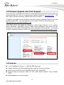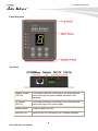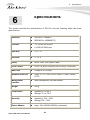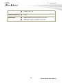
1
DS-100 Device Server User’s Manual Copyright and Disclaimer Copyright & Disclaimer No part of this publication may be reproduced in any form or by any means, whether electronic, mechanical, photocopying, or recording without the written consent of OvisLink Corp. OvisLink Corp. has made the best effort to ensure the accuracy of the information in this user’s guide. However, we are not liable for the inaccuracies or errors in this guide. Please use with caution. All information is subject to change without notice All Trademarks are properties of their respective holders. AirLive DS-100 User’s Manual Copyright and Disclaimer Federal Communications Commission (FCC) Statement This equipment has been tested and found to comply with the limits for a class B computing device pursuant to Subpart J of part 15 of FCC Rules, which are designed to provide reasonable protection against such interference when operated in a commercial environment. European Community (CE) Electromagnetic Compatibility Directive This equipment has been tested and found to comply with the protection requirements of European Emission Standard EN55022/EN61000-3 and the Generic European Immunity Standard EN55024. EMC: EN55022: 2006 + A1: 2007 IEC61000-4-2: 1995 + A1: 1999 + A2: 2000 IEC61000-4-3: 2006 IEC61000-4-4: 2004 class B 4K V CD, 8KV, AD 3V/m 1KV – (power line), 0.5KV – (signal line) Warning: z Self-demolition on Product is strictly prohibited. Damage caused by self-demolition will be charged for repairing fees. z Do not place product at outdoor or sandstorm. z Before installation, please make sure input power supply and product specifications are compatible to each other. AirLive DS-100 User’s Manual Table of Contents Table of Contents 1. Introduction ................................................................................................1 1.1 Overview ..............................................................................................1 1.2 How to Use This Guide ........................................................................3 1.3 Firmware Upgrade and Tech Support ..................................................4 1.4 Features...............................................................................................4 2. Installing the DS-100..................................................................................5 2.1 Before You Start ...................................................................................5 2.2 Package Content .................................................................................5 2.3 Knowing your DS-100 ..........................................................................5 2.4 Hardware Installation ...........................................................................8 2.5 LED Indicator .......................................................................................9 3. Configuring the DS-100 ...........................................................................11 3.1 Important Information.........................................................................11 3.2 Prepare your PC ................................................................................11 3.3 Management Interface .......................................................................12 3.4 Introduction to Web Management......................................................12 3.4.1 Getting into Web Management ..................................................................13 4. Web Management in DS-100 ...................................................................14 4.1 Menu Structure of DS-100 .................................................................14 4.2 System Configuration.........................................................................16 4.2.1 DS-100 Configuration ................................................................................16 4.2.2 Gateway/Controller ....................................................................................17 4.2.3 Firmware Upgrade .....................................................................................22 4.3 Operation Instructions........................................................................24 5. Troubleshooting.......................................................................................25 5.1 Diagnosing LED Indicators ................................................................25 5.2 Cabling...............................................................................................25 6. Specifications...........................................................................................26 7. Network Glossary ....................................................................................28 i AirLive DS-100 User’s Manual 1. Introduction 1 1. Introduction 1.1 Overview Whether you are “operating a wireless hotspot service for generating revenue” or “providing free but controlled wireless internet access to guests”, it would be handy to both the operators and the wireless users if the account information (such as username, password, SSID and etc.) can be readily output to POS printers and printed out as account tickets. DS-100 is designed specifically to operate in conjunction with specific Controllers/Gateways. Typical serial POS printers on the market today may or may not be IP network ready, and it is not practical to integrate each brand one-by-one with Controllers/Gateways. Hence, it has specifically designed a smart device server – DS-100, for two purposes: 1. Attaching before a serial POS printer so that one or more POS printers can be connected to a Controller/Gateway via IP networks. 2. Pre-integrated with the Controller/Gateway so that account generation becomes quick and easy to the operator, simply by a push of buttons on the device. It provides DS-100 and a POS printer as a combo set called Network Ticket Generator. The followings are typical application scenarios: z A small business who wishes to quickly set up a wireless service hotspot for charged internet service may purchase a Gateway, and a Network Ticket Generators set. The Gateway alone serves as an AP and a gateway, Network Ticket Generator enables the registration operator to generate and issue accounts via push buttons on the DS-100 and hand out the account ticket printed out by POS printer. z A corporate has several sites. Deployed at the reception area of each site are with a DS-100 and a POS printer. Guests who need wireless connection to the internet simply need to request the receptionist and obtain a slip with account information. The guest account will automatically expire after the pre-configured time. z A hotel has a Controller/Gateway and multiple APs within it’s hospitality areas. Multiple sets of Network Ticket Generator are distributed at the service desks and lounge counters. The service clerks are able to create accounts for their guests with charged or free internet service depending on the hotel’s service model. 1 AirLive DS-100 User’s Manual 1. Introduction Below are two network diagrams examples using Network Ticket Generator combo set. (1) One Gateway with one Network Ticket Generator set. (2) One Gateway with multiple Network Ticket-Generator sets. Note: The POS printer has an individual manual, therefore, its configuration details is not covered in this guide. AirLive DS-100 User’s Manual 2 1. Introduction Though DS-100 is specifically designed to for on-demand account generation and operate POS printers, it can also be deployed independently to connect other RS232 devices to an Ethernet network for remote operation. If you will be deploying DS-100 independently to manage other serial devices, please carefully set the Serial Settings in DS-100 to match the operating needs of your serial device. Note: If you connect other serial device to DS-100 and are unable to remotely operate your connected serial device, please check that: z The settings under Serial Settings of DS-100 are configured to match your serial device operating requirements. z If your serial device application operates on pure serial communication then you need to setup a COM port redirector. 1.2 How to Use This Guide DS-100 is a device server. Main function is to play a bridge between RS-232 and RJ-45 It is recommended that you read through the entire user’s guide whenever possible. The user guide is divided into different chapters. You should read at least go through the first 2 chapters before attempting to install the device. Recommended Reading Chapter 1: This chapter explains the basic information for DS-100. It is a must read. Chapter 2: This chapter is about hardware installation. entire chapter. You should read through the Chapter 3: 3.1 Important Information: This section has information of default setting such as IP, Username, and Password. 3.3 Management Interface: This section introduces Web management. 3.4 Introduction to Web Management: This section tells you how to get into the WebUI using HTTP. Chapter 4: This chapter explains all of the management functions via Web management. Chapter 6: This chapter shows technical specification of DS-100. Chapter 7: Explanation on network technical terms from A to Z. Highly recommended for reference when you encounter an unfamiliar term. 3 AirLive DS-100 User’s Manual 1. Introduction 1.3 Firmware Upgrade and Tech Support If you encounter a technical issue that can not be resolved by information on this guide, we recommend that you visit our comprehensive website support at www.airlive.com. The tech support FAQ are frequently updated with latest information. In addition, you might find new firmwares that either increase software functions or provide bug fixes for DS-100. You can reach our on-line support center at the following link: http://www.airlive.com/support/support_2.jsp Since 2009, AirLive has added the “Newsletter Instant Support System” on our website. AirLive Newsletter subscribers receives instant email notifications when there are new download or tech support FAQ updates for their subscribed AirLive models. To become an AirLive newsletter member, please visit: http://www.airlive.com/member/member_3.jsp 1.4 Features 1 x 10/100Mbps RJ-45 port + 2 x RS-232 DB9 Serial port Trigger the Built-in On-Demand Billing Plan inside the M-series Controller Flow Control: RTS/CTS and DTR/DSR (RS-232 only), XON/XOFF Supports Network Protocols: ICMP, IP, TCP, UDP, DHCP, BOOTP, Telnet, SNMP, HTTP Web Management via web browser AirLive DS-100 User’s Manual 4 2. Installing the DS-100 2 2. Installing the DS-100 This chapter describes the hardware features and the hardware installation procedure for the DS-100. For software configuration, please go to chapter 3 for more details. 2.1 Before You Start It is important to read through this section before you install the DS-100. The maximum cabling distance is 100 meters. Make sure that the connection between DS-100 and PC/NB is well established Always check the LED lights for troubleshooting 2.2 Package Content Unpack the contents of the DS-100 and verify them against the checklist below. One unit of DS-100 Power Adapter User Guide (CD-ROM) Quick Installation Guide Compare the contents of your DS-100 package with the standard checklist above. If any item is missing or damaged, please contact your local dealer for service. 2.3 Knowing your DS-100 Below are descriptions and diagrams of the product: 5 AirLive DS-100 User’s Manual 2. Installing the DS-100 Panel Overview Top Panel Adapter Socket (12V/1A) The power socket for connecting to an external power source through the power adapter provided in the package. DC Socket (DC12V) The power socket for connecting to an external power source through a DC power supply. Restart Button Press to restart DS-100. Ethernet Port Ethernet port for connecting to a Controller/Gateway. AirLive DS-100 User’s Manual 6 2. Installing the DS-100 Bottom Panel COM 1 Serial Port for connection with a POS printer. COM 2 Serial Port for connection with a POS printer. Used for back up when COM 1 malfunctions. Main Panel OPTION For future use. INC Increase the numeric display for selecting a billing plan number. COM For switching the output to COM1 or COM2. FUNCTION Press this button followed by selecting a number and press Enter will perform a specific action. The available 7 AirLive DS-100 User’s Manual 2. Installing the DS-100 combinations are as follows: FUNTION + 1 + ENTER: Print out the IP address of DS-100. FUNTION + 8 + ENTER: Enter panel test mode. FUNTION + 9 + ENTER: Reset DS-100 to factory default. FUNTION + 0 + ENTER: Lock the panel of DS-100. To Unlock, select your lock number and press ENTER DEC Decrease the numeric display for selecting a billing plan number. ENTER Create and print out an account for the chosen billing plan. 2.4 Hardware Installation The following diagram illustrates how to connect DS-100 to the POS printer and Gateways/Controllers. Please follow the steps described below to install hardware: (1) Attach DS-100 to a power source, either through adaptors provided in the package or through DC socket with a DC power supply. (2) Attach POS printer to a power source, through adaptors provided in the package and AirLive DS-100 User’s Manual 8 2. Installing the DS-100 turn on the power switch situated on the left side of the device. (3) Connect POS printer to the COM1 port of DS-100 by a RS-232 cable provided within POS printer package. (4) Connect DS-100 to the LAN port of your Gateway/Controller by an Ethernet cable. Note: You need to connect to the correct LAN port if your Gateway/Controller is operating in Port-based mode. A. Make sure mounting surface on the bottom of the DS-100 is grease and dust free. B. Remove adhesive backing from your Rubber Feet. C. Apply the Rubber Feet to each corner on the bottom of the DS-100. These footpads can prevent the Switch from shock/vibration. 2.5 LED Indicator The LED Indicators gives real-time information of systematic operation status. The following table provides descriptions of LED status and their meaning. POWER TURNED ON WHEN PROPERLY CONNECT TO POWER SUPPLY. COM 1 Turned on when output is switched to COM1. 9 AirLive DS-100 User’s Manual 2. Installing the DS-100 Note: COM 2 When COM 1 and COM 2 are blinking simultaneously, this means that Terminal Server configuration is not set correctly. Please check the settings in Terminal Server of your Gateway/Controller. When COM 1 and COM 2 are turned on simultaneously, this means that the system is in safe mode. Turned on when output is switched to COM2. Note: When COM 1 and COM 2 are blinking simultaneously, this means that Terminal Server configuration is not set correctly. Please check the settings in Terminal Server of your Gateway/Controller. When COM 1 and COM 2 are turned on simultaneously, this means that the system is in safe mode. Link / Act Turned on when LAN port is connected to an upstream networking device such as a switch or Gateway/Controller. 100 Mbps Turned on when LAN port is connected. 7 Segment Displays an integer between 0 ~ 9 which indicates the billing plan number selected. AirLive DS-100 User’s Manual 10 3. Configuring DS-100 3 3. Configuring the DS-100 DS-100 is designed specifically to operate in conjunction with all Gateways/Controllers. If you are not using default settings, before connecting DS-100 to your Gateway/Controller, some configurations steps are required. The configuration instructions for Gateways/Controllers and DS-100 are covered in the following sections. 3.1 Important Information The following information will help you to get start quickly. However, we recommend you to read through the entire manual before you start. Please note the username and password are case sensitive. The default IP address is 192.168.1.10 The default Subnet Mask is 255.255.255.0 The default Gateway is 192.168.1.254 3.2 Prepare your PC The DS-100 can be managed remotely by a PC through RJ-45 cable. The default IP address of the DS-100 is 192.168.1.10 with a subnet mask of 255.255.255.0. This means the IP address of the PC should be in the range of 192.168.1.2 to 192.168.1.253 (do not include 192.168.1.10). To prepare your PC for management with the DS-100, please do the following: 1. Connect your PC directly to the copper port of DS-100 2. Set your PC’s IP address manually to 192.168.1.100 (or other address in the same subnet) 11 AirLive DS-100 User’s Manual 3. Configuring DS-100 You are ready now to configure the DS-100 by using your PC. 3.3 Management Interface The DS-100 can be configured using on the Web management interfaces. Web Management (HTTP): You can manage your DS-100 by simply typing its IP address in the web browser. Most functions of DS-100 can be accessed by web management inter face. We recommend using this interface for initial configurations. To begin, simply enter DS-100’s IP address (default is 192.168.1.10) on the web browser. 3.4 Introduction to Web Management The DS-100 offers Web Management interfaces for users. Users can easily access and control DS-100 via web browsers. The Web-Based Management supports Internet Explorer 5.0. It is based on Java Applets with an aim to reduce network bandwidth consumption, enhance access speed and present an easy viewing screen. AirLive DS-100 User’s Manual 12 3. Configuring DS-100 Note: By default, IE5.0 or later version does not allow Java Applets to open sockets. The user has to explicitly modify the browser setting to enable Java Applets to use network ports. 3.4.1 Getting into Web Management Web Management (HTTP) 1. Launch the Internet Explorer. 2. Type http://192.168.1.10. Press “Enter”. 3. The home screen of the Web-based management appears. 13 AirLive DS-100 User’s Manual 4. Web Management in SNMP-GSH2404L 4 4. Web Management in DS-100 In this chapter, we will explain all settings in web management interface. Please be sure to read through Chapter 3’s “Introduction to Web Management” first. 4.1 Menu Structure of DS-100 The web management menu of DS-100 is divided into 4 parts: Serial Settings, Network Settings, Utilities, Status. AirLive DS-100 User’s Manual 14 4. Web Management in DS-100 Serial Settings (corresponding to POS printer) Data Baud Rate Select the desired baud rate. (The number of characters per second transferred) Data Bits Select the number of bits in each character. Data Parity Choose between Even or Odd for error detection, or select None for no error detection. Stop Bits Choose the number of stop bits to be sent at the end of every character. Electronic devices usually use 1 bit, slower electromechanical devices use 1.5 bit. Flow Control Choose the method of flow control to pause and resume the transmission of data to coordinate with printer speed. Select None if flow control is not required. Network Settings Static IP Address The static IP address assigned to DS-100. Static Subnet Mask The subnet mask of DS-100. Static Default Gateway The default gateway of DS-100. Static DNS Server Set the DNS server used by DS-100. Transmit Timer TCP transmit timer, set the desired value or use default value. When the timer expires for a sent packet, sender will retransmit the packet. Server Listening Port Set the port number for communication with the Gateway/Controller. Lock Password This attribute is the integer between 0 ~ 9 that will be set as the password for unlocking the main panel. Utilities Firmware Upgrade Firmware of DS-100 can be upgraded by clicking the Apply button. Note: Upgrade preparations are required before upgrade, please refer to Appendix B. Firmware Upgrade 15 AirLive DS-100 User’s Manual 4. Web Management in DS-100 Restart Click Apply to restart DS-100 device. Reset to Factory Default Click Apply to reset DS-100 to factory default settings. Status Software Version The current software version running on DS-100. 4.2 System Configuration DS-100 is designed specifically to operate in conjunction with all Gateways/Controllers. If you are not using default settings, before connecting DS-100 to your Gateway/Controller, some configurations steps are required. The configuration instructions for Gateways/Controllers and DS-100 are covered in the following sections. 4.2.1 DS-100 Configuration DS-100 supports web based configuration. By factory default, DS-100 web interface can be accessed with IP address: 192.168.1.10 Subnet Mask: 255.255.255.0 Default Gateway: 192.168.1.254 Step1: Configure administrator PC’s TCP/IP settings with a static IP address that is under the same subnet mask as DS-100. For example: 192.168.1.100 AirLive DS-100 User’s Manual 16 4. Web Management in DS-100 Step2: Attach DS-100 to a power supply using the adapter provided in the package. Connect the administrator PC to the Ethernet Port of DS-100 via an Ethernet cable. Launch a web browser and type in the default IP address of DS-100 in the address field (http://192.168.1.10), the web interface of DS-100 should appear. Step3: Change DS-100 Network Settings if necessary so that the IP address of DS-100 is under the same subnet as the Gateway/Controller’s interface, which DS-100 will be connected to. Click Apply to save the settings. 4.2.2 Gateway/Controller Configuration procedures are similar on all Gateway/Controller models, the following instruction steps uses WIAS-1200G as example. 17 AirLive DS-100 User’s Manual 4. Web Management in DS-100 Step1: Connect administrator PC to your WIAS-1200G and access the Web management interface. Step2: Enter the configuration page of the Service Zone which DS-100 will be connected to. Check to make sure that the network settings of DS-100 are under the same subnet as this service zone. AirLive DS-100 User’s Manual 18 4. Web Management in DS-100 Step3: Enter Authentication Configuration page Enter User Authentication Æ Authentication Configuration page, and click On-demand User. 19 AirLive DS-100 User’s Manual 4. Web Management in DS-100 Step 4: Define Terminal Server setting in WIAS-1200G Click Configuration in Terminal Server setting and configure further information AirLive DS-100 User’s Manual 20 4. Web Management in DS-100 Step 5: Input DS-100’s IP address/Port number into the column Fill in DS-100’s IP address and Port number into WIAS-1200G Terminal Server setting. Click Apply to save the setting. Step 6: Edit and enable desired billing plans. 21 AirLive DS-100 User’s Manual 4. Web Management in DS-100 4.2.3 Firmware Upgrade Software tools tftpd32 is required in the upgrade procedure, please download and install tftpd32 before you proceed further. Note: Tftpd32 can be downloaded from the following link: http://tftpd32.jounin.net/tftpd32.html Step1: Place the new firmware of DS-100 on a local location (for example desktop) in the PC that is accessing DS-100’s web interface and performing the upgrade. Step2: Configure the TCP/IP settings of your PC with an IP address under the same subnet mask as DS-100. For example 192.168.1.20 Step3: Launch tftpd32 and click the DHCP tab. 1. In “Current Directory” field, browse for the location path where the firmware is stored. 2. Enter the IP address of your PC in “Server interfaces” field. 3. In “IP pool starting address” field, enter the start IP address of an IP segment that is available for allocation. 4. Set the size of the IP pool. 5. Enter the firmware filename in “Boot file field”. 6. Enter 255.255.0.0 in the “Mask” field. 7. Click Save button. Note: Please make sure that the location path and the firmware for upgrade is correct. AirLive DS-100 User’s Manual 22 4. Web Management in DS-100 Step4: Click Apply of Firmware Upgrade in DS-100’s web interface. DS-100 will automatically restart and connect to tftpd32 server set in Step3 as a DHCP client, download the firmware and perform the upgrade. Progress can be observed on tftpd32. Step5: When completed, check the information displayed at Software Version, DS-100 have successfully upgraded to the new firmware. 23 AirLive DS-100 User’s Manual 4. Web Management in DS-100 4.3 Operation Instructions After completing the Hardware Setup and the devices are physically connected, the system is ready for operation. This section will describe how to operate DS-100 to print out tickets for enabled billing plans. 1. Select an enabled billing plan number on DS-100 by INC or DEC button. The numeric LED display on the center of the device represents the billing plan number currently selected. 2. Press ENTER button on DS-100 to create and print out an on-demand account of the selected billing plan. POS PRINTER will print out the ticket with the text format (Without background image) configured on your Gateway/Controller in Ticket Customization. Note: If you are unable to get a ticket printout after pressing ENTER, please check if the selected plan is enabled. AirLive DS-100 User’s Manual 24 5. Troubleshooting 5 5. Troubleshooting This section is intended to help you solve the most common problems on the DS-100. 5.1 Diagnosing LED Indicators The DS-100 can be easily monitored through panel indicators to assist in identifying problems, which describes common problems you may encounter and where you can find possible solutions. Please refer to Chapter 2.7 for detailed information. If the power indicator does turn on when the power cord is plugged in, you may have a problem with power outlet, or power cord. However, if the Switch powers off after running for a while check for loose power connections, power losses or surges at power outlet. If you still cannot resolve the problem, contact your local dealer for assistance. 5.2 Cabling RJ-45 ports use unshielded twisted-pair (UTP) or shield twisted-pair (STP) cable for RJ-45 connections: 100Ω Category 3, 4 or 5 cable for 10Mbps connections or 100Ω Category 5 cable for 100Mbps connections. Also be sure that the length of any twisted-pair connection does not exceed 100 meters (328 feet). Gigabit port should use Cat-5 or cat-5e cable for 1000Mbps connections. The length does not exceed 100 meters. RS-232 Serial port: a common type of electrical connector used particularly in computers. They are among the largest common connectors used with computers. The one side of cable connecting to DS-100 should be DB-9 Female plug, the other side depends on POS printer’s specification. 25 AirLive DS-100 User’s Manual 6. Specifications 6 6. Specifications This section provides the specifications of DS-100, and the following table lists these specifications. z IEEE802.3 10BASE-T z IEEE802.3u 100BASE-TX z 1 x 10/100/ RJ-45 port z 2 x RS-232 DB-9 port Data Bits z 5, 6, 7, 8 Stop Bits z 1, 1.5, 2 Parity z None, Even, Odd, Space, Mark Flow Control z RTS/CTS and DTR/DSR (RS-232 only), XON/XOFF Baud rate z 50 bps to 921.6 Kbps Network Protocols z ICMP, IP, TCP, UDP, DHCP, BOOTP, Telnet, SNMP, HTTP Management Interface z Web management via web browser Weight z 580 g Temperature z Operating: 0 to 40°C z Storage: -10 to 70°C z Operating: 10% ~ 90% z Storage: 5% ~ 90% z Input: 100~240VAC 50/60Hz (maximum) Standard Interface Humidity Power Adapter AirLive DS-100 User’s Manual 26 6. Specifications z Output: 12V / 1A Produce Weight (g) z 580 g Dimensions z Without ears: 90.00 x 109.39 x 31.27 mm z With ears: 116.00 x 109.39 x 31.27 mm 27 AirLive DS-100 User’s Manual 7. Network Glossary 7 7. Network Glossary The network glossary contains explanation or information about common terms used in wireless networking products. Some of information in this glossary might be outdated, please use with caution. 100Base-TX Also known as 802.3u. The IEEE standard defines how to transmit Fast Ethernet 100Mbps using Cat.5 UTP/STP cable. The 100Base-TX standard is backward compatible with the 10Mbps 10-BaseT standard. DHCP Dynamic Hosting Configuration Protocol. A protocol that enables a server to dynamically assign IP addresses. When DHCP is used, whenever a computer logs onto the network, it automatically gets an IP address assigned by DHCP server. A DHCP server can either be a designed PC on the network or another network device, such as a router. Firmware The program that runs inside embedded device such as AP or Switch. Many network devices are firmware upgradeable through web interface or utility program. FTP File Transfer Protocol. A standard protocol for sending files between computer over a TCP/IP network and the internet. IP Address IP (Internet Protocol) is a Layer 3 network protocol that is the basis of all Internet communication. An IP address is 32-bit number that identifies each sender or receiver of information that is sent across the Internet. An IP address has two parts: an identifier of a AirLive DS-100 User’s Manual 28 7. Network Glossary particular network on the Internet and an identifier of the particular device (which can be a server or a workstation) within that network. The new IPv6 specification supports 128-bit IP address format. Packet A unit of data sent over a network. Subnet Mask An address code mask that determines the size of the network. An IP subnet are determined by performing a BIT-wise AND operation between the IP address and the subnet mask. By changing the subnet mask, you can change the scope and size of a network. TFTP Trivial File transfer Protocol. A file transfer protocol, with the functionality of a very basic form of FTP. It is used to transfer small amounts of data between hosts on a network, such as Switch firmware. 29 AirLive DS-100 User’s Manual