1
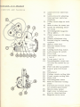
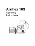
p
OPERATING MANUAL
for
ARRIFLEX® 16S
(STANDARD)
The following
diagram
pages
may be kept folded out for your
convenience
in identifying operating parts white reading the
instructions.
DIAGRAM
showing
OF
external
ARRIFLEX
control
R IF LE X
controls
16 S
and
(Standard)
features
1)
2)
3)
4)
5)
6)
7)
8)
9)
10)
11)
12)
13)
14)
15)
16)
17)
18)
19)
20)
21)
22)
23)
24)
25)
26)
27)
28)
29)
Lock screw for matte box
boom
Lock screws for adjusting
front and rear matte box
standards
Follow focus wings on each
lens
Slide-in shoe for matte box
Eyelet for attaching shoulder strap
Interchangeable
magazine
200 or 400 ft.
Finder eyepiece with rubber
eyecup
Diopter adjustment
ring
Knurled ring for removing
eyepiece
Battery cable lock
External buckle switch
override
Locking start/stop
switch
Lock re lease for switch
Cover lock
Lens socket lock levers
( 1 of 6 )
Turret grip ( 1 of 3 )
Interchangeable
torque motor (only one needed for camera)
Feed- and take-up spindles
Contour grip with thumb
rest
Tachometer
Footage counter setting disk
Frame counter setting disk
Motor lock
Interchangeable
motor
Knob for manually turning
motor
Forward and reverse
switch
for variable
speed motor
Battery cable socket
Light cover in finder eyepiece in closed position
Magazine cavity cover
CONGRATULATIONS
You now own an
picture cameras
ARRIFLEX,
ever made.
one of the finest,
Soon this new ARRIFLEX
will be at work for
form to your entire satisfaction.
most versatile
you.
motion
We know it will per-
As a member of the ARRIFLEX family,
you are cordially
invited to call
on us at any time for advice or assistance.
If you use the ARRIFLEX in
a partic ularly interesting,
complicated,
diffic ult or unus ual application,
won't you please write to us about it? We will be glad to hear from you.
IMPORTANT
Please be sure to fill out and mail the guarantee
card which accompanies
your camera.
This not only makes the guarantee
valid, but it also permits
us to serve you better should you have any technical or service problems
in the future.
As we keep a permanent
record
you better in case of theft.
Each
1 )
2)
3 )
4)
5 )
6)
7)
8 )
9 )
10 )
ARRIFLEX
l
\, 'J""
SUPPLIED
cards,
we can also help
WITH
Test Film taken with camera
Battery cable with attached ground connector
cable for torque motor
Sturdy leather shoulder strap
Fountain-pen
type brush for cleaning optical surfaces
(when cap is put
on rear of brush holder,
brush is pushed out)
Plastic
skewer for cleaning emulsion from film gate
Bottle with special ca rne r a oil
Tube of special grease for lens cavities of camera and lens mounts
Pressure
oiler
Guarantee
Card
Instruction
Manual
I
~~, -.
16 S is
of all registration
-,
~
I_N_ST_R_U_C_TI_O_N_S_F_O_R_~JQ_A_R_R_IF_L_E_X_1_6_S
OPERATING
HOLDING
INSTRUCTIONS
ARRIFLEX
16 S
(Standard)
~
FOR
CA MERA
Place thumb of right hand between contour grip and side of camera,
while
the other fingers reach forward around the "bulge" where they are free to
actuate the follow-focus
grips and diaphragm
ring of the lens in taking position.
Place palm of left hand around finder housing on left side of camera,
gers over
ON-OFF
switch.
Thus camera can be held steady easily
comfortably.
When switch is pressed
release
lever is pushed
down,
in.
it remains
locked
In down-position
finand
until its
An accessory
PISTOL GRIP with or without shoulder brace is also available. It is attached to the tripod socket and has its own release
trigger
which connects through switch behind tripod socket. (See separate
instructions for Pistol Grip).
SIGHTING
Place right eye against finder eyecup. An eyeglass
wearer
should raise his
glasses
to his forehead and sight without them. For left eye viewing, the
eyec up may be turned around.
(C lick- stops ~)
If shutter
is closed,
turn transport
knob in center
of motor
to open it.
First focus eye to ground glass by turning the knurled adjustment
ring at
the eyepiece until grain structure
of ground glass appears
sharp.
You may
want to do this without lens in socket.
The adjustment
ring should then be
locked in place by either of the lock levers.
Ir\
Then focus on subject by a ct uat i ng focusing mount of lens.
For critical
sharpness,
always focus lens with diaphragm
wide open. This is important
to remember
as the optical system of the Arriflex
finder is so bright that
a brilliant
image can be seen even when lens is stopped down.
Most Arriflex
lenses
stopped down without
have clicking diaphragm
stops
removing camera from eye.
so that the lens can be
1
r-
~N_S_T_R_U_C_T_~O_N_S_F_O_R
__ ~-A-R-R-I-FL-E-X--16_S
~
While the optical system of the finder is constructed
so that it prevents
light from entering and fogging film, the eyepiece must be shielded from
direct (horizontal)
sunlight or powerful spotlight if eye is removed.
For
this purpose a light cover is provided inside the rubber eyecup. During
filming always press eye firmly against eyecup or close the cover door
on the eyepiece.
FINDER
WITH
DETACHABLE
INTERCHANGEABLE
GROUND
The detachable
BLIMP without
of the BLIMP.
EYEPIECE
GLASS
AND
eyepiece permits
using the camera in the Arriflex
16
the eyepiece while attaching the eyepiece on the outside
It also permits attaching the PERISC OPIC ACCESSOR Y FINDER, which
facilitates
viewing from the side or the top (for instance if camera is on
a microscope
or copy stand), or viewing with the left eye when a 400 -Tt ,
MAGA ZINE is attached to camera (See illustration
in Arriflex folder).
The eyepiece can be removed by turning the knurled chrome-plated
collar clockwis e (camera in shooting position).
To replace it, engage keyed flange properly and turn collar counter-clockwise.
The rubber eyecup can be turned
right or left eye viewing.
freely
The eyepiece cover door also turns
open along long end of rubber cup.
on its click-stop
freely
bearing
and should always
for
be set to
The standard ground glass,
supplied with the camera,
can be interchanged
with SPECIAL GROUND GLASSES with cross hair reticle,
or TV field, or
clear glass with reference
reticle for cinemicroscopy
(See price list for
details).
(Such installations
are a service department
job and must be
done only by skilled,
experienced
technicians
with special tools).
The Arriflex
eyepiece has a high accommodation
diopter adjustment-collar with lock lever. For people, whose eyesight requires
further correction, it is possible to fit PRESCRIPTION
LENSES into the eyepiece.
(Write for further information).
Another worthwhile accessory
is the FOAM RUBBER EYE CUSHION
which fits over the rubber eyecup. It is particularly
convenient in perspiring hot weather and it is also desirable
when different cameramen
use the same camera.
Each cameraman
can have his own eye cushion.
2
~
I_NS_T_R_U_C_T_IO_N_S__ FO_R__ ~
MIRROR
REFLEX
__ AR_R_I_F_LE_X__ 16_S
~
SHUTTER
The mirror
reflex shutter is the heart of the Arriflex.
It rotates at a 450
angle between lens and film plane and reflects
upon the ground glass of
the viewfinder exactly the same image as is registered
on the film.
The
light rays reach the film through the lens w i t h out any interference
while
the shutter is open; they are reflected
to the ground glass only while the
shutter is closed.
Thus the film, as well as the eye, always get 100 % of
the light transmitted
by the taking lens.
The shutter
opening
Camera
8
12
16
24
32
48
of 1800 results
Speed
FPS
FPS
FPS
FPS
FPS
FPS
in the following
exposures:
Exposures
1/16
1/24
1/32
1/48
1/64
1/96
see.
sec.
sec.
sec,
sec.
sec,
As this table indicates,
the exposure
can be calculated
for any camera
speed by doubling the FPS figure and reading the result as a fraction of
a second.
TURRET
The Arriflex
16 features
a heavy duty three-lens
t ur r e t . The lenses
are
0
mounted in a divergent
manner (21 ) to prevent optical and mechanical
interference
between wide-angle
and telephoto lenses.
Thus a Lo rn m wideangle lens can be mounted simultaneously
with a 300mm (12") Tele-Kilar
without danger of interference,
It features
the same lens mounts as the Arriflex
35, whose advantages
are their p.os i t iv e locking device,
the speed and ease of changing
lenses,
and the large s-e at i ng ring, which permits
even relatively
long and heavy
lenses to be attached accurately
and securely.
Very long or heavy lenses,
of course,
must always be supported by means of a proper ARRI LENS
CRADLE ( Acces sory Item).
Three turret grips make it easy to rotate the turret which comes to a positive stop whenever a lens socket is over the film aperture.
Never grasp
lenses for the purpose of turning turret around!
The lens located nearest
is in the taking position.
the contour
grip on the right
side of the camera
3
I NSTRUCTIONS
FOR
__
A_R_R_I_FL_E_X_l_6_S
-----------i
The back of each grip - protruding
on left side of camera and visible with
the left eye, while the right eye is looking through the finder
- is coded
with one, two, or three dots to indicate if wide-angle,
normal,
or tele photo lens is in taking pos it i on ,
To remove lens from turret press the two spring-loaded
locking levers at
the base of the lens socket together,
with thumb and index finger of one
hand, while lifting lens out with the other.
To insert lens, again press locking levers together and place lens into socket. Align the channel in lens mount with the guide key in the socket.
Release the levers and the lens is locked into position.
LENSES
FOR
ARRIFLEX
16
are made by the world's best optical manufacturers
and represent
the ultimate in quality.
The lenses available for the Arriflex
16 range in focal
length from 5. 7mm up. The standard
lenses are equipped with (ollow-focus grips and most have diaphragm
click- stops. Thus the lens can be stopped
down from behind the camera without direct observation.
With due consideration
for the professional
use for which they are intended,
all Arriflex
lenses are triple-checked
for best optical performance
before
they are mounted for the Arriflex;
only the very finest lenses are selected.
( See Arriflex
price list for makes,
focal lengths and maximum apertures).
Among telephoto lenses,
we recommend
the KILFITT KILARS available
up
to 600 rnrn . They are of outstanding
quality and workmanship.
The relatively low cost of these lenses is due only to the fact that they can be manufactured in large quantities
as they are primarily
made for 35mm still cameras.
A 11KILARS feature a removable
A rriflex mount.
EXTENSION TUBES and
VARIABLE HELICAL EXTENSION ADAPTERS are available for filming at
extremely
close distances
(Macro Cinematography).
For close- up work, the Kilfitt MAKR O-KILAR lenses are ideal. The Kilfitt
90 mm Makro-Kilar
focuses continuously
from infinity to 811 from the sub ject. The 40 mm Makro-Kilar
focuses from infinity to 4".
A variety of variable
focal length ( 11 Zo orn'"] lenses are also available which
are martufactured
to Arriflex
specifications
and standards.
(See price list
for details).
With your Arrifle~
16 these lenses require no special finder.
The field size, focus and depth of field are always clearly shown in the camera s unique mirror - shutter reflex system.
1
4
~
IN_S_T_R_U_C_T_IO_N_S_F_O_R __ ~
LENS
__AR_R_I_F_LE_X__ 16_S
-4
SELECTION
It is the factory's
p o li c y to s e l l Arriflex
cameras
on ly compLete
quality Len s e s; Inferior
Lenses mounted on these cameras
would
n ul lif y the great expense of precision
engineering
that goes into
ra, but would not yield the superb results
of which the ArrifLex
with top
not only
each cameis capable.
The standard
set of Lenses for the ArrifLex 16 is usually of l o rnrn , 25mm,
and 50mm focal length. These lenses are used most frequently
by pro fessional
cameramen
and work best with the matte box.
When a longer focal length lens is mounted on the turret,
the matte box
often cannot be brought close enough to the l orn rn or 25mm lenses to work
properly,
and the lens must therefore
first be removed when using the
l ornrn or 25mm lens.
Whenever a lens socket IS empty,
is supplied with the camera.
Extremely
port
CAUTION
long or heavy
lenses
it must
be capped
may require
a cradle
with a cavity
or other
cap which
special
sup-
When buying additional
lenses for your Arriflex
in the future,
insist on "genuine" Arriflex
lenses,
Not every lens in Arriflex mount is genuine.
It would be false economy to pay for
mechanical
Arriflex
camera perfection
and to jeopardize
the
investment
with "orphaned"
lenses that are frequently
of poor
optical quality, poorly mounted,
poorly centered,
and that are
too expensive at any price.
If in doubt whether a lens is genuine, please write to us, mentioning
make and serial number.
DETACHABLE
BELLOWS
FILTER
HOLDER
TYPE
MATTE
BOX
AND
This indispensable
accessory'
fits over the lens turret.
To attach the camera,
slide the end of the boom into the special shoe on the front of the camera
housing; it is tightened and locked into position by turning the knurled knob
at the front of the boom.
The rear standard
of the matte box is movable to accommodate
lenses of
various lengths.
Its front is also adjustable
to give maximum efficiency and
to prevent vignetting irrespective
of the lens used.
SPECIAL EFFECT
MATTES
s e r t e d into the front frame.
( Accessory
Item
- see price
list)
can be
m-
5
~~
I_N_ST_R_U_C_TI_O_N_S_F_O_R_~_A_R_R_IF_L_E_X_l_6_S
~
The two filter stages accept rectangular
ARRI OPTICAL GLASS FILTERS,
or ARRI FILTER HOLDER with frame for 2" square Kodak gelatine or glass
filters.
One of the stages can be rotated for use with GRADUA TED or POLARIZING
FILTERS.
( For available
filters
see price list).
The rear opening of the matte box is threaded
to accept
ring for circular
Series VIII glass-mounted
filters.
Use of the matte box improves
out it!
In addition,
it permits
MOT
a screw-in
adapter
picture quality considerably;
never shoot withone filter to be used with most lenses.
OR S
An 8 Volt VARIABLE SPEED MOTOR is generally
used with the Arriflex
16. After opening lock lever,
the motor may be pulled out of the camera
housing and interchanged
with other motors - GOVERNOR CONTROLLED
CONSTANT SPEED MOTOR, SYNCHRONOUS MOTOR, ANIMATION MOTOR.
When variable
speed motor is put back into place, care must be taken to
line up the locating pin against the keyway in body casting and pushing it all
the way in, as otherwise
it will not make contact.
By turning the motor shell, a built-in
rheostat
is actuated that regulates
the
speed of the motor,
which - in turn - can be read in frames
per second on
the tachometer.
The figures around the motor shell are arbitrary
ones, and
after a little experience
permit the operator
to reset the camera quickly for
any desired
speed. (With a fully charged 8 Volt battery the rheostat
will be
set between 3 and 4 to give 24 FPS).
Other motors available
in the Arriflex
program
are GOVERNOR CONTROLLED MOTOR, SYNCHRONOUS MOTOR, and TIME LAPSE MOTOR. (See
price list and illustrated
Arriflex
folder).
All motors
are
POWER
SOURCES!
IMPORTANT:
interchangeable
Power
are:
instantly
without
the need of tools.
BATTERIES
r eq ui r e rrie nt s for Arriflex
8 Volts (under
starting
surge
16 with
load); 3.6 Amperes
up to 6 Amperes.
It is vital that the source
of delivering
this current.
of electric
400 ft.
magazine
running;
power
be fully capable
6
I_NS_T_R_U_C_T_~O_N_S
__FO_R__ ~-A-R-R-I-FL-E-X--16_S
r-
"VOLTABLOC"
~
BATTERIES
These are steel-cased,
long life Nickel Cadmium batteries
in which the
electrolyte
is an alkaline.
Each cell is hermetically
sealed and never requires the addition of water or the usual battery maintenance.
Each battery is supplied complete with a miniature
charger built into the case. Dol 1a r for
Dol 1a r i tis
pro b a b 1Y the
b est
buy.
The
following two models are available:
2.'y_O_~-_~
8.4 Volt 4AH . It will run the Arriflex
1000 ft. of film.
16 for approximately
~~~.9J...:E_ It
has a selector
switch which permits
drawing
8.4 Volt 8AH for use with Arriflex
16
16.8 VoU 4 AH for use with Arriflex
35.
This battery with the 8.4 Volt 8 AH setting is especially
filming se s sions pa r t i c ularly with magazine s and torque
LEAD ACID ( 8 Volt)
desirable
motor.
for long
BA TTERIES
These are small storage batteries
chemically
similar
to the usual automobile battery.
Initial cost is low, while its service
life is between two to
three years.
Maximum life depends on proper maintenance.
A separate
trickle charger
is available for these batteries.
Be sure to read charging
and maintenance
instructions
which accompany each battery,
as the life
and service of the battery depends upon proper care.
AUTOMOBILE
BATTERY
Your A rriflex may be ope rated from a 6 Volt auto batte ry in cas e of need.
Maximum camera speed will be approximately
24 FPS. The camera may
also be operated from a 12 Volt auto battery
pro v ide d the battery is
tapped for 8 Volts.
DR Y CELL
BA TTER Y PACK
Generally,
the footage capacity of the storage batteries
is more than enough
for a day's shooting,
and the battery can then be recharged
over night. Where
this is not possible (on expeditions,
etc.) or convenient,
the Arriflex
can
also be run from a dry cell bat t e r y pack. ( Please write for further information) .
HOUSE
CURRENT
To use the Arriflex
on 110 Volt AC house
current,
a step-down
transformer
7
~
I_N_ST_R_U_C_TI_O_N_S_F_O_R_~_A_R_R_I_FL_E_X_l_6_S
~
rectifier
is necessary.
An excellent unit of this type is the COMBINATION
POWER SUPPLY /BA TTERY CHARGER (see separate
specifications).
It is
ideal for indoor shooting and has its own ammeter,
volt meter and rheostat
built-in.
It can also be used to charge lead acid batteries.
It must not
be
used to charge nicke 1 cadmium (Vo ltabloc) batteries.
It is important
to remember
also pos sible directly from
CAMERA
that with the synch motor camera operation
110 - 120 Volt, 60 cycle AC power lines.
is
CONTROLS
The motor has a graduated
rheostat
ring controlling
the camera speed, indicated as "frames
per second" by the tachometer,
which registers
up to
50 frames per second.
The Arriflex
can be run as slowly as 6 frames per
second (shooting inanimate
sub jects under poor lighting conditions) and has
continuous
speed s up to 50 FPS.
Below the tachometer
can be zeroed easily
are the film footage counter and frame
by their respective
setting disks.
counter.
A knurled disk marked "R" - "F" is located at the back of the motor.
turned all the way to "FII (click- stop), the camera will run For war
the disk turned to IIR II (click- stop), the camera will Rever
-; e .
Both
When
d; with
As much film as is desired can be reversed,
and any frame can easily be
located by means of the two counters which register
both ways. C aut ion
both,
camera
motor
and
magazine
torque
motor,
must
be set
tor
un 1 nth
e sam e d ire c t ion,
i , e.
BOT H for
---ward
or
BOTH
reverse;
The film transport
knob in the very center of the motor is used to turn the
shutter over by hand for sighting,
and to actuate registration
pin and film
transport
claw during loading operation.
OPENING
AND
LOADING
(Please
refer
to Diagram
Turn cover lock from IICII to 11011 and lift off cover. Place
firmly on upper spindle.
Pull off about 2 feet of film.
on Page 9)
100 ft film
spool
Open film gate by pressing
down on its latch knob and swing the pressure
pad assembly
open on its hinges.
Before threading film,
open pressure
roller assembly A by pressing
button B. Thread film around sprocket drum
C. Swing off pressure
roller D-1, if necessary.
Then arrest
film by swinging back pre s sure rolle r D-l. Lead film to film gate E by forming a loop
according to marking in camera body. Register
pin F must be in disengaged
pos i t i on ,
8
r------------------------------------~-~----------------------------------,
INSTRUCTIONS
FOR
(__
A_R_R_IF_l_E_X_l_6_S
--t
Place film into gate in such a way that a perforation
hole is exactly in line
with registration
pin. Hold film down with two fingers of one hand at both
ends of gate and turn transport
knob until the registration
pin locks film
in place. Then close gate.
- Thread film around sprocket
drum G and close pressure
roller D2.
The sprocket
spindles have single sprockets
only ( to permit use of sound
perforated
film).
It is important
to seat film properly
by moving it back
and forth with two fingers over each spindle until you can feel that a sprocket has engaged a perforation.
The pressure
roller assembly
can be rocked
on its pivot and so, when the upper sprocket has been threaded,
the roller
can be rocked to hold film in place. When the lower sprocket
has been threaded, the lower portion can, in turn, be rocked into place.
Move a few inches of film through gate by manually turning transport
knob
at end of motor housing clockwise.
Connect camera to battery.
Push down
internal
switch and watch about 2 feet of film roll through camera.
(Note:
A " 100 ft. roll" of film on a daylight loading spool actually measures
106
feet to permit enough leader and trailer).
Close camera
cover and move lock to "C".
released
and in open position,
as otherwise
Set footage
, .. 111
.. ~
counter
and frame
counter
Be sure that outside switch
cover cannot be closed.
to "0" by their
control
IS
disks.
E
F
H
FILM FA TH AND LOADING
DIAGRAM
DIAGRAM OF BUCKLE SWITCH
WITH MANUAL OVERRIDE
9
I NSTRUCTIONS
FOR ~_AR_R_I_FL_E_X_l_6_S
BUCKLE
SWITCH
WITH
ME C H A N ISM
(PLease refer
MANUAL
to diagram
---I
OVERRIDE
on Page 9).
The buckle switch works properly
only if the lower film loop is formed
exactly according
to the marking in camera body. When end of film has
passed film gate, the Lower loop shortens,
thereby pulling up the switch
r o l Ie r H, which in turn cuts off the camera motor. Switching on the camera again is only possible after the pressure
roller assembly
A has been
opened and closed as described
in threading instructions.
This manipulation, which is always being performed
when film is threaded into camera,
causes the buckle switch to reset itself.
If the pressure
roller assembly
A is not closed properly,
the camera will not start.
Any shortening
of the
Lower loop ( e. g. film jam in camera) actuates
the buckle switch.
IMPORTANT
Never
actuate
the
switch
roller
H
by
ha nd l
The buckle switch override
mechanism
permits
to cut the buckle switch out
of the electrical
circ uit of the camera at the option of the camera operator.
Experience
has shown that on certain adverse and rare occasions,
particularly due to shock or vibration,
the micro switch of the buckle switch becomes inoperative,
thus switching the camera off. By means of the override
mechanism
the cameraman
in the field can quickly restart
the camera without removing the camera door.
In cas e of doubt whethe r the buckle switch was unintentionally
triggered
by
impacts or vibration,
or whether it was actuated due to a film jam, it is recommended
to open the camera
cover to check film path and sacrifice
a few
inches of film rather than use the external override
control.
By pressing
the push button D below the viewfinder,
the buckle switch override mechanism
is actuated and the break in the circuit due to the release
or the malfunction
of the buckle switch
is bridged,
To reset the buckle
switch, the toggle lever U of the buckle switch override
mechanism
is turned
by hand to its initial position,
interrupting
its overriding
function.
FILM
GATE
The film gate is extra long ( 3 inches) and has an oversized
rear pressure
pad and a side pres sure rail. It has cros s stages around the picture frame
both on front and back plates and "film breathing"
is therefore
impossible.
Made of stainless
steel,
lapped to high precision
and wear chrome-pLated,
the Arriflex
film gate also prevents
film scratching.
10
~_N_ST_R_U_C_Tl_O_N_S_F_O_R_~-A-R-R-IF-L-E-X-1-6_S
r-
REGISTRATION
PIN
FILM
MOVEMENT
seen when the f ilrn gate IS open just above
is to locate
the f ilm precisely
and hold it
The registration
transport
claw.
pin can be
Its function
place
rrio rrie nt of exposure.
during
a perfect,
the
f r a rrie line,
precise
FILM
TRANSPORT
easier.
Thus
and
it ensures
accurate
trick
rock-steady
the
in
pictures,
a n irna t iori fi lrn in g ,
and
CLAW
f ilm transport
The
loading
~
claw
Watch
engages
its
f'i lrn f r o rn the lens
the
action
by turning
transport
side,
thus
rna k in g
knobs.
MAGAZINE
The
ca me r a housing
accepts
the 400 ft. ARRI rna g a z i n e . A lightprotects
the rria ga z i n e s lot. When the rna ga z in e is attached,
the
top of the
tight
cover
cover
m us t first
be r e rnov ed , The
and has internal
rna ga z irie .
wiring
to actuate
See detailed
instructions
its torque
rriot o r .
Y
DELIVER
Both
spindles
for
AND
have
TAKE
- UP
The
knurled
When
the
spindle
f i lrn is
goes forward
turning,
thus
If between
caution
out,
of the
the
loading
takes
to do the
the
down
400 ft.
the
button
of c a m e r a serve
engraved
spindles
of f iIrn through.
and
the
f il rn gate
Before
to see
properly
Aft~r
and
that
that
the
turn
and
thus
last
take
the
rna ga z in e and
starting
to f i lrn again,
and
claw
not
in place
in any
caITle-
in center
of spindle
to take
up fi Irn slack
indicate
or
run
the
it had
with
arrows.
c a rrie r a is to be transported
following:
rna ga z irie operation
f iIrn spool
to hold
push
on outside
running,
and
or backward.
When f il rn has run off, the
indicating
that the ca rrie r a is e rn pty ,
feet
perforation
port.
disks
for
up rno t o r , needed
take-
SPINDLES
an a ut o rna.t ic lock
t h e rn in direction
ready
extra
attaching
ra position.
To take f il m spool
and tilt ca rrie r a sideways.
by turning
c a rne r a is
the
stored,
f i Lrn
spindle
stops
it is a good
pre-
a p p r ox irna t e l y one or two
open
registration
Slipped
whether
delivery
during
the
carn e r a door
pin
engage
the
storage
the
f ilm
or trans-
11
~_N_ST_R_U_C_T_~O_N_S_F_O_R_~-A-R-R-I-FL-E-X-l-6_S
r-
TRIPOD
~
SOCKETS
Two tripod sockets,
in bottom of camera
one European
housing.
and one American
type,
are
provided
EYELETS
Two eyelets
on camera
ra, to prevent accidental
CARRYING
permit
fall.
use of shoulder
strap,
supplied
with came-
CASES
Two carrying
cases are made for the Arriflex
16. They are especially
designed for safe storage and transport
of Arriflex
cameras.
Covered with
hammered
aluminum,
they are red velevet lined and have chrome-plated
brass hardware
and channeling around cover to insure dustproof,
moistureproof storage.
The inside is partitioned
to hold camera and accessories
safely. A "genuine" Arriflex
case is a good investment
for the protection
of your ca rne r a ;
Model "A" Case
Accepts camera with 3 lenses,
matte box, filters and
small acces sorie s.
Size: l5x9x8" - It is designed to fit under an airplane
seat.
Model liB" Case
Accepts camera with 3 lenses,
matte box, two 400 ft.
magazines,
torque motor for magazines,
shoulder pod,
filters and other accessories.
ARRIFLEX
SHOULDER
POD
This simple but efficient accessory
is a MUST for the cinematographer
who is compelled
to shoot hand-held for any length of time. Please refer
the enclosed booklet for more detailed information.
ARRIFLEX
PISTOL
to
GRIP
It permits
the cameraman
to hold the camera and release
the shutter with
the left hand, while the right hand balances
the camera and operates
the
follow-focus.
See detailed description
in the enclosed booklet.
12
~
I_N_ST_R_U_C_T_IO_N_S_F_O_R_~_A_R_R_I_FL_E_X_l_6_S
COMBINATION
PISTOL
GRIP/
An attractive
combination
of pistol
hand-held
camera stability,
Pistol
chanism to control camera"
start"
see enclosed booklet.
SERVICING
AND
SHOULDER
~
POD
grip and shoulder pod for maximum
grip has internal trigger
switch meand s to p'"; For further information
II
MAINTENANCE
The Arriflex
16S is built with utmost precision
and inherent ruggedness.
It will give absolute satisfaction
if treated as any precision
instrument
should be treated,
and if serviced at regular intervals,
consistent
with the
amount of use.
The
most
important
rule
KEEP
CAMERA SPOTLESSLY
is
CLEAN
-
INSIDE AND OUT ~
Particular
attention must be given to the film gate. It is precision-lapped
and chrome-plated
to prevent film emulsion to settle,
However,
due to the
comparatively
great length of film gate and pressure
plate to ensure Hlaximum film registration,
some emulsion deposit is inevitable.
This will
vary with the type of film used, humidity and other factors.
The
film
gate
should
be
brushed
out
at
least
after
every
100
ft.
roll
and
it
must
be
c a r-e f u Ll y inspected and
thoroughly
cleaned
at
least
after
every
400
ft.
roll.
Remove
emulsion
deposit
with
the
plastic
s k ewe r sup p I i e d wit h the
c a mer a ( NEVER METAL).
If
emulsion
is
hardened
on film
gate,
remove
it
with
a Q-tip
dipped
i n
acetone.
Use
very
little
acetone
and
d o n t let
it
touch
anything
else,
as it also destroys
paint. After cleaning,
polish gently with chamois or other soft material.
i
From time to time lens mounts and the three lens sockets in turret
should
be cleaned to remove dirt and dust which will adhere.
After such cleaning,
re-Iubricate
lightly with the special grease supplied with the camera.
The lubricants
used with the Arriflex
down to _200 F.
On special
ized at our
ever, such
temperate
are
suitable
for use in temperatures
request and for extra charge,
Arriflex
cameras
can be winterService Department
to function at still lower temperatures.
Howcameras
will have to be normalized
again, if intended for use in
or hot climate s.
13
~
__AR_R_I_F_LE_X__ 16_S
I_NS_T_R_U_C_T_IO_N_S__ FO_R__ ~
~
OILING
Your c a rn e r a has been properly
for operation.
Do not
oil
lubricated
at the factory
before
using
and
ready
IS
After each run of 30 000 ft. of f i lm through the c a rn e r a , ca rne r a should
be lightly oiled at two oil valves rn a r ke d with arrows
(one near the f i Im
gate, and one near the spindle).
Only use the ball and pressure
oiler
supplied with your ca rrie r a and the special oil contained therein.
Do
not
0 v e r 0 i I
too rnuc h oiling is as bad as too little :
By observing
the following
ration of your Arriflex
:
"DON'Ts"
you will protect
f i lrn at high
the continued
ope-
DON'T
run c a rrie r a without
speeds.
DON'T
a tt e rnpt to disas s e rrib le the optical
done by factory-trained
personnel.
DON'T
touch rrii r r o r shutter with fingers.
Clean it only with soft ca rrie l
hair brush.
In any case, a spot on the rn i r r o r does not affect the
picture.
DON'T
rn ix up covers
on each cover
DON'T
use old or shrunk
to the perforation
cations.
ITlechanisITl.
of different
c a m e r a s (serial
and ca rne r a}.
f i Irn ; the registration
pitch
of fresh
This
should
n urnbe r s are
pin's
be
engraved
stroke is adjusted
to ASA specifi-
f i lrn , according
DON'T
aUow ca rrie r a s to be serviced
flex c a m e r a s require
special
in unqualified
service
shops.
knowledge and experience.
Arri-
DON'T
neglect to have your ca.rrie r a serviced
after a pp r ox irna t e l y every
100 000 ft., or every two years,
whichever
COITles first.
Service
should be rno r e frequent
under adverse
conditions.
Our Technical
Service De pa r t rne n t w e l c orn e s your inquiries
and is particularly anxious to hear about unusual applications
of the Arriflex
ca rne r a ,
GUARANTEE
Arriflex
e q ui prne n t IS carefully
checked before s h i prn e nt , and is guaranteed to the original
purchaser
for a period of ON E
year,
~r~~~~~~h~~
0~3~~~~~0~~~~~~~~~~~~~~~~~~~~~~~~~~JQj~~~~~~3~~~~_
~~.5:~a~~.
The guarantee
does not cover
da ma ge caused
by accident,
ta rn-
14
~-----------------------------------~~~------------------~--------------,
INSTRUCTIONS
pering,
FOR
(mIID_A_R_R_IF_L_E_X_l_6_S
~
or misuse.
Repair and adjustment
of Arriflex
equipment which may become necessary during the guarantee
period because of original defects in material
or workmanship,
will be made by us without charge if the equipment is
sent to us prepaid and properly
packed.
Except for such repair or adjustment,
Arriflex
out warranty
or other liability of any kind.
All features
and specifications
are
subject
equipment
to change
1S
sold with-
without
notice.
We have inserted
a price list and general literature
into this manual,
in order to show the new Arriflex
owner the many accessories
and adaptations
which
make the Arriflex
a "system"
camera
and enlarge
its a_pplications.
ARRIFLEX
CORPORATION
257 Park Avenue South
New York, N. Y. 10010
A29/l0-364
OF
AMERICA
826 No. Cole Avenue
Hollywood,
Calif. 90038
15