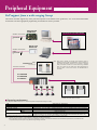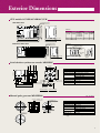
1
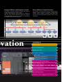
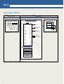
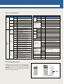
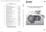
ADVANCED AND EVER ADVANCING
MOTION CONTROLLERS
Mitsubishi Electric Corporation Nagoya Works is a factory certified for ISO14001
(standards for environmental management systems) and ISO9001(standards for
quality assurance managememt systems)
Motion Control Structured to your Specific Application
Powerful Programming Environment
Various motion control models are available based on your
specific application requirements. Models includes the
A171SH(up to 4 control axes) for smaller scale applications
up to the A173UH(up to 32 control axes) for larger scale
applications. In addition, various motion controller operating
system software packages are available. The OS with
optimum control functions is selected based on your
application requirements. Simple, compact and powerful
motion control, custom tailored for your application needs.
A powerful programming environment insures
minimal system start up and programming time,
as well as powerful, easy to use diagnostic and
monitoring utilities. System development time is
greatly reduced, saving valuable time and money.
High Speed Synchronous Communication
Network : SSCNET
SSCNET(Servo System Controller NETwork) is a highspeed synchronous serial communication network that
realized increased performance and reliability over
conventional control networks. SSCNET allows for batch
control of up to 32-axes thus simple one touch connection
bus cabling, fast and simple connection.
Unity and Inno
1
Integrated Motion and Sequence Control
Diverse Motion Control Functions
The motion controller integrates motion and sequence
control functions into a single compact
package, thus reducing overall system size, complexity
and cost. The motion controller utilities the industry
leading MELSEC-A series PLC modules for networking,
I/O and special function operations.
The system is provided with diverse and innovative
motion control functions including interpolation
control, speed control, electronic cam and locus
control, so even complicated operations can be freely
controlled.
CPU module
configuration
Sequence CPU
(SCPU)
Motion CPU
(PCPU)
Common memory
PLC bus
Motion bus
SSCNET
MELSEC
I/O module
MELSEC
MELSEC
intelligent module communication module
MELSEC
I/O module
Motion
related module
Servo amplifier Servo amplifier Servo amplifier
The motion controller carries out multi CPU type control, which connects the sequence control SCPU,
having an independent I/O bus, and the motion control PCPU with a common memory.
ovation
Motor
Motor
Motor
CONTENTS
Main Features
1
System Configuration
3
Products Line-Up
5
OS Software Packages
6
Motion SFC
7
SV13 (Conveyor Assenmbly use)
17
SV22 (Automatic Machinery use)
21
Overview of CPU Performance
25
Software Packages List
28
System Components
29
Peripheral Equipment
31
Exterior Dimensions
32
Combinations of Servo Amplifiers and Servo Motors 33
2
System Configuration
A171SH/A172SH/A173UH
CPU base unit
A172B/A175B/A178B/
A178B-S1/A178B-S2*/A178B-S3*
*For A173UHCPU only
Teaching unit (Note-2)
A30TU-E/A31TU-E
SSCNET (Max. 8 axes per 1 line)
Cable
MR-HBUS M
MR-J2HBUS M
MR-J2HBUS M-A
Manual pulse
generator
MR-HDP01
Pulse generator/
synchronous encoder
interface unit
A172SENC
Servo amplifier
MR-H- BN
MR-J2S- B
MR-J2- B
Servo motor
3
Serial absolute
synchronous
encoder
MR-HENC
A1S series
I/O unit
Terminal
connector
MR-TM
MR-A-TM
Motion controller integrates motion and sequence control into a single compact package.
(220mm wide, 130mm high and 110mm deep) (A172B CPU base use).
By connecting to a PLC extension base, I/O capabilities are expanded A171SH : max. 512 points, A172SH : max.
1024* points and A173UH : max. 2048* points. The extension base can connect to max. one step.
*The real I/O points can be used within the range of main base and one extension base.
Connects to MELSECNET II, MELSECNET/B, MELSECNET/10 and CC-Link networks
(Note-1)
By connecting MR-H-BN/MR-J2S-B/MR-J2-B model servo amplifiers with the SSCNET communication network, 50W to
55kW servo motors can be batch controlled A171SH : max. 4-axes, A172SH : max. 8-axes and A173UH : max. 32-axes.
PLC bus
Cable
A1SC
B
Graphic operation terminal
(GOT)(Note-3)(Note-4)
PLC extension base unit (Note-5)
A1S65B/A1S68B/A168B (GOT compatible)
A1S series
I/O unit
A1S series special
function unit
Power supply module
A1S6 PN
A1S series
I/O unit
A1S series
special function unit
(Note-1) : When using A171SH/A172SH, restrictions are as follows.
MELSECNET II, MELSECNET/B : local station only (The range of address : each of B and W is 0 to 3FF)
MELSECNET/10 : Normal station only (The range of address : each of B and W is 0 to 1024 points.)
(Note-2) : When using a teaching unit A31TU-E with dead-man switch, a dedicated connecting cable A31TUCBL03M is required between the CPU module and A31TU-E connector.
If the A31TU-E is connected directly to the RS422 connector of the CPU without using a dedicated cable, the A31TU-E will not operate at all.
After disconnecting the A31TU-E, attach a short-circuit connector A31TUSHORTCON for A31TUCBL.
(Note-3) : With a graphic operations terminal, PCPU data(servo program, parameters, mechanical system programs etc.) cannot be displayed.
(Note-4) : When using the PLC extension base and bus connection type GOT, select the A168B as the PLC extension base.
When not using the PLC extension base, you can connect the bus connection type GOTdirectly to the extension connector of the CPU base unit.
(Note-5) : PLC extension base without extra power supply cannot be used.
4
Product Line-Up
A171SHCPUN
Max.4
A171SHCPUN
PLC CPU
PLC program capacity
Real I/O points
Processing speed
(sequence command)
Control axes
Servo program capacity
Servo amplifier
Servo motor capacity
Network
PLC extension
Specifications
A2SHCPU equivalent
14k steps
512 points
0.25µs/step
Max. 4
13k steps
External servo amp connected by SSCNET
50W to 55kW
MELSECNET ll/B(local station only)
MELSECNET/10(normal station only)
CC-Link
Max. 1 base unit
A172SHCPUN
Max.8
A172SHCPUN
PLC CPU
PLC program capacity
Real I/O points
Processing speed
(sequence command)
Servo program capacity
Control axes
Servo amplifier
Servo motor capacity
Network
PLC extension
Specifications
A2SHCPU memory, I/O increase equivalent
30k steps
1024 points (Note)
0.25µs/step
13k steps
Max. 8
External servo amp connected by SSCNET
50W to 55kW
MELSECNET ll/B(local station only)
MELSECNET/10(normal station only)
CC-Link
Max. 1 base unit
(Note) : The real I/O point can be used within the range of CPU base and one extension base.
A173UHCPU
Max.32
A173UHCPU(-SI)
PLC CPU
PLC program capacity
Real I/O points
Processing speed
(sequence command)
Servo program capacity
Control axes
Servo amplifier
Servo motor capacity
Network
PLC extension
Specifications
A3UCPU equivalent
30k steps x2
2048 points (Note)
0.15µs/step
14k steps
Max. 32
External servo amp connected by SSCNET
50W to 55kW
MELSECNET ll/B/10,CC-Link
Max. 1 base unit
(Note) : The real I/O point can be used within the range of CPU base and one extension base.
5
OS Software Packages
Application Tailored Software Packages
The motion controller operating system software is specifically
tailored and packed with functionality specific for your
application needs.
Dramatic reductions in product design costs and simpler
programming environments over conventional motion controllers
realized great time and money savings.
Install
OS Software Line-up
Conveyor Assembly Use
Automatic Machinery Use
Motion SFC
Motion SFC
SV13
SV13
SV22
SV22
Offer constant-speed control, speed control, 1 to 4-axes linear
interpolation and 2-axes circular interpolation, etc. Ideal for use in
conveyors and assembly machines.
Electronic component assembly
Inserter
Feeder
Molder
Conveying equipment
Paint applicator
Chip mounter
Wafer slicer
Loader/Unloader
Bonding machine
X-Y table
Dedicated language
Linear interpolation(1 to 4-axes)
Circular interpolation
Constant-speed control
Fixed-pitch feed
Speed change control
Speed control
Speed-positionswitching
Teaching function
Provides simultaneous control multiple servo motors and offers software
cam control. Ideal for use in automatic machinery.
Press feeder
Food processing
Food packaging
Winding machine
Spinning machine
Textile machine
Printing machine
Book binder
Tire molder
Paper-making machine
Mechanical support
language
Synchronous control
Electronic shaft
Electronic clutch
Electronic cam
Draw control
6
Motion SFC
Greatly strengthed programming environment and event processing.
The Motion SFC function to describes the motion control program in flow chart form. By describing the program of the
CPU(PCPU) which controls the motion in a suitable Motion SFC for the event processing, serial operation of the machine is
controlled by PCPU, aiding the event response.
Motion SFC (Sequential Function Chart)
Easy-to-read and comprehend flow chart description.
• Programming can be carried out with an image that describes the flow chart with the machine operation procedures.
• A process control program can be created easily, and the control details can be visualized.
Controlling the series of machine operations with PCPU
• Using the Motion SFC, the servo control, operation and I/O control can be carried out in a batch with the PCPU.
• There is no need to start the servo program from the CPU (SCPU) that controls the sequence.
Multi-task processing
• The Motion SFC allows for multi-task program operation.
• By using parallel distribution in one program, multiple steps can be executed simultaneously.
Motion SFC description
Flow chart description which easy-to-view
and understand.
As the outline operation of the process control is
described as a flow chart, the entire operations can be
viewed at a glance.
The operation details can be described as a comment so
an easy-to-understand program can be created.
The program has a hierarchical structure, so detailed
operations can be described for each step.
Seal processing
Reduced
display
P10
Enhanced operation function
The operation expression can be described in the original
state.
Compatible with 64-bit floating point operation.
Various arithmetic functions including trigonometric
functions, square root and natural logarithm are provided.
The motion registers (#0 to #8191) have been added for
Motion SFC operations.
G100
G120
Beginning wait
Cancellation wait
F30
F40
Data calculation
Cancellation data set
Comment
display
F10
G200
Work ready
P20
K100
Operation start
F20
G100
G120
G150
F30
F40
G160
G200
K200
K100
G210
[F 30]
// 1 axis real processing data calculation
DOL=LONG((SIN(#100)+110F) 300)
// Processing status set
SET M100=X12+M120
*
P20
G300
[G 200]
PXO //Work ready completion sensor ON?
F150
P10
7
F : Operation control step
G: Transition(condition wait)
K : Motion control step
[K 100]
1 ABS-2
Axis
1,
D 100 µm
Axis
2,
D 200 µm
Combined speed D 300 mm/min
Extended
display
Powerful event processing functions
Multi-CPU method that strengthens event
processing function
Minimized variation in control response time
With the conventional SV13/SV22, the series of machine
operations were controlled by the SCPU so a variation
occurred in the response time per seguence scan.
However, this can be minimized by the strengthened
Motion SFC event processing function, so the scan time
can be suppressed, and variations in product machining
can be reduced.
MELSEC
I/O module
SCPU scan process
The multi-point I/O control and monitoring operations
can be appointed to the SCPU by the ladder program, and
the servo control and high-speed response control can be
appointed to the PCPU by the Motion SFC program. This
balances the scan process and event process, and further
utilizes the multi-CPU configuration.
Common
memory
PCPU event process
MELSEC
I/O module
(PX/PY)
X
MELSEC
intelligent
module
MELSEC
communication
module
Y
M
B
Motion related
module
F
D
T
C
MELSEC
display unit
W
SSCNET
related device
Ladder description suitable for scan process
Motion SFC description suitable for event process
(Importance laid on condition control)
(Importance laid on sequential control, pursuit of event responsiveness)
Event process
This process waits for the conditions to be established
(event to occur) with the changes in the input signal state or
device value, and carries out high-speed response control
(signal output control, servo motor start and speed change,
etc.) when the conditions are established.
Examples of events
Input signal turned ON.
Operation results reached constant value.
Set time elapsed.
Positioning was completed.
8
Motion SFC
High-speed response using step
execution method
Sequence program
Motion SFC program
All steps are executed with constant scan.
Only active steps are executed following shift conditions.
The sequence program uses a scan execution method
to execute all steps with constant scanning. However,
with the Motion SFC, the step execution method
executes only the active steps following the shift
conditions. Thus, the operation process can be
reduced, and processing and response control can be
realized.
X0000
PLS M100
Work movement control
SET M101
[G 1]
PX0 //Start (PX0=ON) wait
M100
M101 M2001 M2002
RST M101
[K 1]
1 ABS-2
axis
1,
D 200 µm
axis
2,
D 202 µm
Combined speed D 204 mm/min
SET M102
[G 2]
PX1 //1st process machining completion (PX1: ON) wait
SVST J1 J2
K1
M102 M2001
K2
SVST J1
RST M102
[K 2]
1 ABS-1
axis
speed
SET M103
[G 3]
PX2 //2nd process machining completion (PX2: ON) wait
SET Y0008
[F 1]
SET PY8 //Completion signal (PY8)ON
1,
D 300 µm
D 202 mm/min
M103 M2001
RST M103
END
Exclusive description unique to
motion control
Shift
WAIT
WAIT ON/OFF
If shift is applied immediately after the motion
control step, the shift will be executed without
waiting for the motion control operation to end.
K100
K200
ON M0
G100
G200
K300
If WAIT is executed immediately after the motion
control step, WAIT will be executed after waiting for
the motion control operation to end.
If WAIT ON/WAIT OFF is commanded just before
the motion control step, the details of the motion
control will be pre-read, and preparation for starting
will be carried out. The operation will start
immediately when the designated bit device turns
ON/OFF.
Selective branch and parallel branch
Selective branching
When all routes shift after branch, or WAIT is issued
for all routes, selective branch will be applied.
Parallel branch is applied in all other cases.
K1
With selective branch, the route for which the shift
conditions are established first are executed.
With parallel branch, several routes connected in
parallel are executed simultaneously. The process
waits at the connection point, and shifts to the next
process after execution of all routes is completed.
Multi-task processing
With the Motion SFC, when several programs are
started, the process is carried out with multi-task
operation.
Multiple steps can be simultaneously executed with
parallel branching even within one program.
A program that executes multiple processes
simultaneously, or a program that groups the control
axis for independent movements can be created
easily.
A highly independent programming is possible
according to the process details, so an easy-tocomprehend program can be created.
9
Parallel branching
G0
G1
G2
G3
K2
K3
F1
K2
K3
K4
G1
G2
G3
G6
F2
G4
G4
Wait
MAIN
REAL
F
F
P
SUB
F
P
G
Parallel branch
F
K
F
K
G
G
G
G
F
F
F
F
P
G
G
K
K
G
END
G
F
P
High-response to external inputs
I/O output
Sequence program
This is used to measure the response time of the
output signal in respect to the input signal from an
external source.
With the sequence program, there is a delay and
variation equal to the response time 20ms and
approximately the scan time.
With the Motion SFC, the response time and
variation are approximately 3ms.
X10
Motion SFC program
M100
[G 100]
SET PY0=PX10*M100
Y0
PLC scan time 20ms
X10
(S-I/O input)
PX10
(P-I/O input)
OFF
OFF
ON
Y0
(S-I/O output)
ON
PY0
(P-I/O output)
OFF
OFF
ON
ON
5ms/div
20ms
S-I/O: PLC slot I/O
P-I/O: Motion slot I/O
3ms
(Approx. PLC scan time)
→
→
Great reduction in servo program start time
Start up of servo program
Sequence program
This is an example of starting the servo program
using the input signal from an external source as a
trigger.
When starting with the sequence program, a delay
and variation equal to 20ms and approximately the
scan time occurs from the input of the external signal
to start-up of the speed command.
Motion SFC program
X10 M2001
ON PX0010
SVST J1 K100
K100
PLC scan time 20ms
X10
(S-I/O input)
OFF
ON
PX10
(P-I/O input)
OFF
ON
With the Motion SFC, the speed command will start
up with a response time of less than 10ms and
variation of approximately 3ms.
Speed command
(Amplifier monitor terminal)
Speed command
(Amplifier monitor terminal)
10ms/div
10ms/div
20ms
S-I/O: PLC slot I/O
P-I/O: Motion slot I/O
6ms
9ms
(Approx. PLC scan time)
→
Continuous start-up of servo program
Sequence program
This shows an example of starting-up the 1-axis and
3-axes linear interpolation program K300 immediately
after starting-up the 1-axis and 2-axes linear
interpolation program K200.
When continuously starting-up the servo program
with the sequence program, a delay and variation of
approximately 30ms will occur. This is because the
PLC scan time is 20ms, and the refresh cycle for the
start acceptance flag M2001, which is the interlock is
10ms.
Motion SFC program
M10 M2001 M2002
M20 M2001 M2003
K200
SVST J1J2 K200
RST M10
SET M20
SVST J1J3 K300
G100
K300
PLC scan time 20ms
Speed command
Speed command
Axis 1
Axis 1
Axis 2
Axis 2
An interlock is not required with the Motion SFC,
and the start delay will be approximately 7ms.
Axis 3
Axis 3
10ms/div
30ms
10ms/div
7ms
(Approx. PLC scan time +10ms)
→
10
Motion SFC
Example applications
System configuration
Timing chart
X-Y table
To ISA bus
Z
Z-axis
X
Y
X-Y imposition
SSC I/F board
PC/AT compatible
Drill axis
Drill breakage
sensor
Hole opening
confirmation sensor
Motion controller
Sensor input/
Drill output
Machine
<Printed board hole opener>
Point data
I/O
Servo amplifier
SSCNET
Machine's key points
1. High-speed forwarding of a hole breakage data from a personal computer.
2. High-speed monitor function in a personal computer.
3. High-speed start of Z-axis after X-Y table positioning is completed.
4. High-speed start of X-Y axis after printed a board hole opening(Z-axis rises from printed board position).
5. High-speed save operation when drill breakage.
New method (Motion SFC SV13)
Previous method (SV13)
SCPU
PCPU
SCPU
PCPU
Start
Start
PLS
M0
SET
M1
SFCS
K0
Start
P0
M0
1 [G0]
//X-Y axis start wait
//(Z-axis current value
//>
= Printed board rising position)
(D842L>=D200L)
M1
DMOV
D842
D202
X-Y table start
<K0>
M4 M2001 M2002
D>=D202 D200
(Z-axis current value >= Printed board rising position)
SVST J1J2 K0
2
1
(X-Y table positioning completed)
M2 M1601
= K1 D813
(Servo program "K0" execution)
RST
M1
RST
M4
SET
M2
2 [K0]
ABS-2
Axis
1, D 0 µm
Axis
2, D 2 µm
Combined speed D 4 mm/min
ABS-2
Axis
1, D 0 µm
Axis
2, D 2 µm
Combined speed D 4 mm/min
M-code
1
[G1]
NOP //Positioning completed wait
3 [F0]
SET PY20 //Drill-axis start
4 [G2]
//X-Y table in-position check
M1602 * M1622
Drill axis start
SET
3
Y20
RST D813
RST
M2
SET
M3
Z-axis start
<K1>
M3 M1602 M1622 M2003
SVST J3 K1
5
4
X-Y table Imposition check
X0000
6
X0001
7
X0001
7
RST
M3
SET
M4
Drill axis stop
RST Y20
8
CPSTART1
Axis
3
Speed
FIN
Acceleration
/deceleration
ABS-1
Axis
3,
ABS-1
Axis
3,
Speed
ABS-1
Axis
3,
Speed
CPEND
D 10 mm/min
200 msec
D 12 µm
D 14 µm
D 20 mm/min
D 16 µm
D 10 mm/min
Processing action 1 to 9 of the previous method corresponds to the new method 1 to 9 .
5 [K1]
CPSTART1
Axis
3
Speed
D 10 mm/min
FIN
Acceleration
200 msec
/deceleration
ABS-1
Axis
3, D 12 µm
ABS-1
Axis
3, D 14 µm
Speed
D 20 mm/min
ABS-1
Axis
3, D 16 µm
Speed
D 10 mm/min
CPEND
Z-axis start
7 [G3]
PX1 //Breaking check
6 [G4]
PXO //Hole opening completed wait
8 [F1]
//Z-axis save operation
(Negative speed change)
CHGV(K3, -100000)
9 RST PY20 //Drill stop
Z-axis save operation
(Negative speed change)
CHGV J3 K-100000
9
SVST: Servo program start request instruction
11
X-Y table start
SFCS: Motion SFC program
start request instruction
END
[F1]
RST PY20 //Drill-stop
8
P0
Control flow (Motion SFC SV13/SV22)
PCPU control range
SCPU control range
(Motion CPU)
(Sequence CPU)
Axis 2
Sample sequence program
SFCS
Sample Motion SFC program
Transfer
K0
Motion SFC
program start
request instruction
Number
of start program designation
20000
10000
[G 100]
M2009 // Servo ON reception flag?
10000
20000
Axis 1
SV13/SV22 real mode
[K 10 : Real]
1 INC-2
Axis
1, 10000 PLS
Axis
2, 20000 PLS
Combined speed
30000 PLS/s
Servo motor start
Sample mechanical system program
Transmission
module
Drive module
(Virtual servo motor)
[F 100]
// Command speed calculation
DOL=#100L+#102L+#104L
[G 200]
M2044 // On virtual mode?
SV22 virtual mode
Virtual servo motor start
[K 100 : Virtual]
1 VF
Axis
1
Speed
D
0 PLS/s
Output module
Motion SFC program also can be automatically
started by the parameter setting.
END
(Cam)
(Roller)
Please refer to P19 regarding control flow of "SV13(without Motion SFC)" and P23 regarding control flow of "SV22(without Motion SFC)".
12
Motion SFC
Various programming tools.
System setting
System setting
Servo data setting
Programming
Motion SFC program editing
Program editing
Instruction wizard
Select instruction
13
Mechanical system editing
Cam deta setting
Ladder editing
GX-Developer
Debugging
Motion SFC monitor
Motion SFC debugging mode
Start-up adjustment
Monitor . Test
Digital oscilloscope
Operation and maintenance
Back-up
Document printing
14
Motion SFC
Motion SFC specifications
Motion SFC chart symbols
Class
Program
start/end
Step
Symbol
Name
Program name
START
Function
Indicates the start (entrance) of the program.
END
END
Indicates the end (exit) of the program.
Motion control step
K
Starts the servo program Kn.
(The servo commands are the same as the conventional SV13/SV22.)
Once execution type
operation control step
F
Executes the operation control program Fn once.
Scan execution type
operation control step
FS
Repeats an operation control program FSn until the next transition condition enables.
Subroutine
call/start step
Program name
Calls or starts a subroutine.
Clear step
CLR Program name
Cancels and ends execution of the designated program.
Shift
(Pre-read transition)
G
Shifts to the next step when the transition condition enables without waiting for the
previous motion control step or subroutine to end.
WAIT
G
Shifts to the next step when the transition conditions enables after the previous motion
control step or subroutine ends.
Transition
WAIT ON
ON bit device
WAIT OFF
OFF bit device
Prepares to start the next motion control step, and immediately outputs a command
when the conditions are established.
Jump
Jump
P
Jumps to the designated pointer Pn within its own program.
Pointer
Pointer
P
Indicates the jump destination pointer (label).
Motion SFC program parameters
The Motion SFC program start method and execution timing are set with the program parameters.
Setting range
Automatically start
Item
Start setting
Do not start automatically
Normal task
Executed
task
Event task
Fixed cycle
External interrupt
PLC interrupt
NMI task
Details
Start at rising edge of PLC READY (M2000)
Start with the Motion SFC program start command SFCS from PLC
Start with "Subroutine call/start" GSUB from the Motion SFC program
Execute in motion main cycle (free time)
Execute in fixed cycle (1.7ms, 3.5ms, 7.1ms, 14.2ms)
Execute when set external interrupt unit (I0 to I15) input turns ON
Execute with interrupt from PLC (When PLC dedicated command ITP is executed)
Execute when set external interrupt unit (I0 to I15) input turns ON
Operation control step and transition commands
Class
Symbol
Function
=
Substitution
+
Addition
Binary
–
Subtraction
operation
Multiplication
*
/
Division
%
Remainder
˜
Bit inversion (complement)
&
Bit logical AND
Bit
I
Bit logical OR
operation
Bit exclusive OR
ˆ
>>
Bit right shift
<<
Bit left shift
–
Sign
Sign inversion (complement of 2)
SHORT Convert to 16-bit integer type (signed)
USHORT Convert to 16-bit integer type (unsigned)
LONG Convert to 32-bit integer type (signed)
Type
ULONG Convert to 32-bit integer type (unsigned)
conversion FLOAT
Regarded as signed data,
and convert into 64-bit floating point type
UFLOAT Regarded as unsigned data,
and convert into 64-bit floating point type
15
Class
Symbol
SIN
COS
TAN
ASIN
ACOS
ATAN
Standard SQRT
LN
function
EXP
ABS
RND
FIX
FUP
BIN
BCD
Bit device (none)
status
!
SET
Bit device RST
control
DOUT
DIN
Function
Sine
Cosine
Tangent
Arcsine
Arccosine
Arctangent
Square root
Natural logarithm
Exponential operation
Absolute value
Round off
Round down
Round up
BCD → BIN conversion
BIN → BCD conversion
ON (normally open contact)
OFF (normally closed contact)
Device set
Device reset
Device output
Device input
Class
Symbol
Function
(none) Logical acknowledge
Logical
!
Logical negation
operation
Logical AND
*
+
Logical OR
==
Equal to
!=
Not equal to
<
Comparison
Less than
operation
<=
Less than or equal to
>
More than
>=
More than or equal to
Motion
CHGV Speed change request
dedicated
CHGT Torque limit value change request
function
EI
Event task enable
DI
Event task disable
Others
NOP
No operation
BMOV Block move
TIME
Time to wait
Sequence dedicated commands
Sequence command
Control details
SFCS
At the rising edge (OFF → ON) of the SFCS command executed by the sequence program,start of the designated the Motion SFC program
is requested.
ITP
An interrupt is issued to the motion CPU (PCPU) at the rising edge (OFF → ON) of the ITP command executed by the sequence program.
The motion CPU executes the active step of the SFC program executed by the "PLC interrupt".
• The functions of the conventional SV13/22 PLC dedicated commands (DSFRP/SVST/DSFLP/CHGA/CHGV/CHGT) are described in the Motion
SFC program, and cannot be described in the sequence program.
List of integrated start-up support software SW3RNC-GSVE software configuration
Software
Installation
Project management
Conveyor assembly software
SW3RN-GSV13P
System setting
Servo data setting
Program editing
Mechanical system editing
(GSV22P only)
Communication
Automatic machinery
software
SW3RN-GSV22P
Monitoring
Testing
Backup
Cam data creation software
SW3RN-CAMP
Cam data creation
Digital oscilloscope software
SW3RN-DOSCP
Digital oscilloscope
Communication system software
SW3RN-SNETP
Communication
system
Communication API
Document printing software
SW3RN-DOCPRNP (Note)
Printing
Ladder editing software
SW3RN-LADDERP
Ladder editing
Function
Installation of the motion OS
Comparison of the motion OS
New creation, setting and reading of projects
Batch management of user files in project units
Setting of system configuration (motion module/servo amplifier/servo motor, etc.)
Setting of high-speed read data
Setting of servo parameters and fixed parameters, etc. (Explanatory diagrams displayed with one-touch help)
Setting of limit switch output data (Output pattern displayed with waveform display function)
Editing of the Motion SFC program, setting of the Motion SFC parameters
Reduced display of the Motion SFC diagram, display of comments, enlarged display
Monitor of the Motion SFC, debugging of the Motion SFC
Editing of mechanical system program
Monitoring of mechanical system program execution state
Setting of SSCNET communication CH.
Writing, reading and comparison of programs and parameters in respect to the motion controller.
Current value monitor, axis monitor, error history
Servo monitor, limit switch output monitor
Servo startup, servo diagnosis
Jog operation, manual pulser operation, zeroing test, program operation
Teaching, error reset, current value change
Backup of motion controller programs and parameters in file
Batch writing of backed up files into the motion CPU
Cam data creation with Cam pattern selection and free curve settings
Graphic display of Cam control status
Data sampling synchronized to operation cycle
Waveform display, dump display and file saving of collected data
Communication task, communication manager, common memory server, SSCNET communication driver
Support of cyclic communication, transient communication, high-speed refresh communication
Communication API functions compatible with VC++/VB
Printing of program, parameter and system settings
(Convert into Word 97 or Excel 97 document format, and print)
Editing of sequence program
Monitoring of sequence program execution
(Note) : Word 97 and Excel 97 and above are required.
16
SV13
(Conveyor Assembly Use)
Simple programming using dedicated commands.
By using easily understood dedicated servo command and sequence commands positioning and locus control can be
programmed as you like.
Control which is considered difficult and complex can be carried out simply using a variety of canned motion control functions.
Example applications
X-Y table control
Sealing
Z-axis
r1
r2
X-axis
Z
Y-axis
X
Y
Sash
Feed control
Fixed-pitch hole drilling
1st speed
2nd speed
3rd speed
1st speed
Speed change
Cushion time
Pause stop
(troque limit)
Time
(high-speed recovery)
Position sensor
Servo motor
Speed
control
Speed
Rotary table indexing
Sensor
operation
Position
control
Time
Roll feeder
Press
Speed
Rotary table
indexing
Servo motor
Time
Roll feeder
Servo motor
17
Example functions
Skip operation
High speed read-out function
This allows a positioning point to be made invalid
during constant-speed control so that positioning
moves on to the next positioning point.
Using a signal from the input unit as a trigger, up to
11data sets(feed current value, variation counter value,
etc.) out of 16 types of data can be read simultaneously
to designated devices.
Uses : Handling positioning eta.
Uses : Measured length, synchronized correction
Negative speed change
Cancel/start function
During position control, movement in the reverse
direction can be made using speed change. Using the
sequence command CHGV, a negative speed can be
set so that the locus is retraced.
This forcibly halts program processing during operation, allowing you to switch to other program.
Uses : Return operations
Uses : Escape operations when errors occur
M-code FIN waiting function
S-curve acceleration/ deceleration
This allow a faster than normal commencement of
positioning to the next point during constant-speed
control.
Using a determined ratio S-curve acceleration/deceleration characteristics can be set. The S-curve
acceleration/deceleration enables smoother start and
stop, and reduces stress on machines.
Uses : High response positioning operation
Position follow-up control
Speed change/pause/restart
By carrying start-up once, the setting value of the
positioning point is detected in real time, and position
control is carried out by tracking the changing settings.
Positioning, speed change during JOG operation as
well as pause and restart can be carried out simply
using the sequence command CHGV.
M-code output function
2 speed controls
During positioning, M-codes between 0 and 255 can
be output at each positioning point.
Two types speed controls are available using position
loops or speed loops.
Dwell time free setting
Limit switch output
Dwell time can be set for any value between 0 and
5000ms.
High-speed output of ON/OFF signals for up to 8
points per axis in response to the real current value
during operation can be made regardeess of the
sequence program.
Parameter block setting
Teaching setting
Common setting items in positioning control can be
set and freely selected as parameter blocks up to a
maximum of 64 types.
Using address teach and program teach, the positioning
points can be taught.
Torque limit value change
Torque limit value change can be carried out simply
during positioning and JOG operation using the
sequence command CHGT.
18
SV13
(Conveyor AssemblyUse)
Control f low (SV13)
SCPU control range
PCPU control range
(Sequence CPU)
(Motion CPU)
Sample sequence program
Sample servo program
(2-axes constant-speed control)
14750
12500
M2001 M2002
SVST J1J2
K10
point
5
Start accept
Servo program
start instruction
<K10>
1
Number of
start program
designation
2
Please refer to P11 regarding control flow of
"Motion SFC SV13".
2-axes constant-speed
control
CPSTART2
Axis
1,
Axis
2,
Speed
Start axis designation
1000.00
(mm/min.)
ICN-2
Axis
1,
10000.0
(µm)
Axis
2,
12500.0
(µm)
Axis
1,
18500.0
(µm)
Axis
ABS
2,
7500.0
(µm)
Auxiliary P 1,
13500.0
(µm)
Auxiliary P 2,
14750.0
(µm)
M-code
3
4
ABS-2
Axis
1,
D2000
(µm)
Axis
2,
D2002
(µm)
11
ABS-2
Axis
1,
0.0
(µm)
Axis
2,
0.0
(µm)
Speed
800.00
M-code
5
12
CPEND
Positioning parameter
System setting
Servo parameters
Fixed parameter
Parameter block
JOG operation data
Limit switch
output data
Please refer to P11 regarding control flow of "Motion SFC SV13"
Combined speed setting
Incremental Iinear
interpolation
Absolute auxiliary
point setting
Circular interpolation
M-code output
10
M-code
19
Axis 2
(mm/min.)
Absolute linear interpolation
Indirect designation
7500
2500
10000
16000
13500 18500
Axis 1
Servo instruction
Positioning control
Instruction
symbol
ABS-1
Processing
Positioning control
Absolute 1-axis positioning
1-axis
INC-1
Incremental 1-axis positioning
ABS-2
Absolute 2-axes linear interpolation
INC-2
Incremental 2-axes linear interpolation
ABS-3
Absolute 3-axes linear interpolation
INC-3
Incremental 3-axes linear interpolation
ABS-4
Absolute 4-axes linear interpolation
INC-4
Incremental 4-axes linear interpolation
ABS
Absolute auxiliary point designation
circular interpolation
INC
Incremental auxiliary point designation
circular interpolation
ABS
Absolute radius designation circular
interpolation less than CW 180°
ABS
Absolute radius designation circular
interpolation CW 1800 or more
ABS
Absolute radius designation circular
interpolation less than CCW 180°
ABS
Absolute radius designation circular
interpolation CCW 180° or more
INC
Incremental radius designation circular
interpolation less than CW 180°
Fixed-pitch
feed
Instruction
symbol
Processing
1-axis
FEED-1
1-axis fixed-pitch feed start
2-axes
FEED-2
2-axes linear interpolation fixed-pitch feed start
3-axes
FEED-3
3-axes linear interpolation fixed-pitch feed start
VSTART
Speed switching control start
VEND
Speed switching control end
VABS
Absolute designation speed switching point
VINC
Incremental designation speed switching point
Forward
VF
Speed control(I) forward rotation start
Reverse
VR
Speed control(I) reverse rotation start
Forward
VVF
Speed control(II) forward rotation start
Reverse
VVR
Speed control(II) reverse rotation start
Forward
VPF
Speed-position control forward rotation start
Reverse
VPR
Speed-position control reverse rotation start
Restart
VPSTART
Speed-position control reverse rotation restart
PFSTART
Position follow-up control start
CPSTART1
1-axis constant-speed control start
CPSTART2
2-axes constant-speed control start
CPSTART3
3-axes constant-speed control start
CPSTART4
4-axes constant-speed control start
CPEND
Constant-speed control end
2-axes
Linear
control
3-axes
Speed-switching
control
4-axes
Auxiliary
point
designation
2-axes
circular
interpolation
control
Radius
designation
Center
point
designation
INC
Incremental radius designation circular
interpolation CW 180° or more
INC
Incremental radius designation circular
interpolation less than CCW 180°
INC
Incremental radius designation circular
interpolation CCW 180° or more
ABS
Absolute center point designation circular
interpolation CW
ABS
Absolute center point designation circular
interpolation CCW
INC
Incremental center point designation
circular interpolation CW
INC
Incremental center point designation
circular interpolation CCW
Speed
control
(I)
Speed
control
(II)
Speedposition
control
Position tracking
control
Constant-speed
control
Repetition of
same control
Used in speed
switching control and
constant-speed
control
FOR-TIMES
FOR-ON
Repeat range start setting
FOR-OFF
NEXT
Repeat range end setting
Simultaneous start
START
Simultaneous start
Zeroing
ZERO
Zeroing start
High-speed oscillation
OSC
High-speed oscillation start
Teaching functions
Teaching unit
Portable teaching units, perfect on-site environments.
In addition, they also have servo programming
functions, data setting, servo monitor and servo testing
functions.
Also, because the A31TU-E is fitted with a dead-man
switch, error safety is assured.
Dead-man
switch
A30TU-E
A31TU-E
(Front panel)
(Rear panel)
20
SV22
(Automatic Machinery Use)
Easy on screen programming using the mechanical support language.
Loaded with a mechanical support language that allows easy programming of the machine mechanism. Ideal for controlling
automated machines such as food machines and wrappers.
By freely combining a variety of software mechanism modules and cam patterns, complex synchronization control and
coordinated control can be achieved easily and low cost.
Example applications
Filling machine
Filling
Nozzle raised and lowered
Conveyance
Nozzle
Filling
Draw control
V
V+Draw
Press conveyance
Press machine
Main press motor
Die
Import conveyor
Synchronous
encoder
Export conveyor
Work
Work
Y-axis servo motor
X-axis servo motor
Three dimensional transfer
Lift (2)
Lift AC servo motor
Lift (1)
Lift AC servo motor
Feed
Feed
AC servo motor
Clamp (2)
Clamp
AC servo motor
Clamp (1)
21
Synchronous control
The servo motor can be operated simultaneously with other motor control conditions. Using the mechanical support language,
synchronous control settings can be made simply, and synchronous operation is carried out with little tracking delay.
A
T
3000r/min
B
Drive module
Motor revolutions
Transmission module
Gear
0.35˚
Position variation
between 2-axes
0.13˚
Output module
(Virtual servo motor)
150.5ms
1-axis position variation
Roller
2-axes position variation
1-axis
Position variation between 2-axes
during synchronous control
2-axes
Synchronous control mechanical system program
Mechanical support language
Software is used for mechanism operation
Easy programming on screen using a mouse
Control of hardware such as main shafts, gears, clutches
and cams is handled by the software mechanical modules,
conventional problems are solved.
The machine is more compact and costs are lower.
There no worries over friction and service life of main
shafts, gear and clutches.
Changing initial setup is simple.
Eliminating mechanical precision errors and boosting
system performance.
Control through advanced software cam
Since cam control is handled by software, there are no
problems with error caused by conventional cam control.
The ideal cam pattern control can be achieved. Ideal in
applications such as raising or lowering control of nozzles
in contact with liquid surfaces, control of amount of filler or
smooth conveyance control. Changing of cams when
product types alter is also easy to handle by simply
adjusting the cam pattern.
Monitor screen with mechanical support language
22
SV22
(Automatic Machinery Use)
Control flow (SV22)
SCPU control range
PCPU control range
(Sequence CPU)
(Motion CPU)
Sample sequence program
M2001
SVST
J1
Sample mechanical system program
Sample servo program
Drive module
Virtual
<K2000>
K2000
Transmission module
Start accept
(Gear)
Servo program
start request
ABS-1
Axis
Speed
1,
100000
1000
Virtual servo
motor in the
mechanical
system
program
start
(Virtual servo motor)
(Clutch)
Operation results
from the transmission
module are output to the
amp unit which sets the
output module.
Positioning parameter
Parameter block
Output
module
JOG operation data
(Cam)
Servo motor control
(Roller)
Servo amplifier
Servo amplifier
Servo motor
Servo motor
Please refer to P11 regarding control flow of "Motion SFC SV22"
Mechanical module list
Mechanism
section
Drive
module
Virtual
axis
Mechanical module
Name
Appearance
Function
Virtual
servo
motor
Used to drive the virtual axis in the
mechanical system program by the servo
program or JOG start.
Synchronous
encoder
Used to drive the virtual axis by input
pulse from an external synchronous
encoder.
Virtual
main shaft
This is a virtual "link shaft" .
The rotation of the drive module is
transferred to the transmission module.
Virtual
auxiliary
input axis
This is the auxiliary input axis for input to
the transmission module "differential gear".
It is automatically displayed when the differential gear and the gear are connected.
Roller
Used when the speed control occurs
at the final output.
Ball screw
Used when the liner positioning occurs
at the final output.
Rotary
table
Used when the angle control occurs at
the final output.
Cam
Used when control other than those
shown above occurs at the final output.
Position control occurs based on the
cam pattern setting data.
There are two cam control modes: the
two-way cam mode and the feed cam
mode.
Output
module
23
Mechanism
section
Mechanical module
Name
Appearance
Gear
Direct
clutch
Transmission
module
Smoothing
clutch
Speed
change
gear
Differential
gear
Function
Transfers the drive module rotation to the
output axis.
The travel valve input from the drive
module multiplied by the set gear ratio,
and transferred to the output axis so that
it moves in the set direction.
Engages/disengages the output module
with the drive module rotation.
When switching the clutch ON/OFF, there is
a direct clutch for direct transfer and a
smoothing clutch for acceleration/deceleration processing which occurs in accordance
with the smoothing time constant setting.
Depending on the application, ON/OFF
mode, address mode or external input
mode can be selected.
As the smoothing method, the time constant setting method or degree of slippage
setting method can be selected.
Used to change the speed of the output
module.
The speed from the input axis side
multiplied by the set speed change ratio
and transferred to the output axis.
The rotation of the auxiliary input axis
subtracted from the rotation of the virtual
main shaft and transferred to the output
axis.
The rotation of the auxiliary input axis
subtracted from the rotation of the virtual
main shaft and transferred to the output
axis. (for connection to the virtual main
shaft)
Software package for creating cam curves
SW3RN-CAMP
This package sets the cam pattern when using software cam control through the mechanical support language. It makes it easy to
freely create highly precise cam patterns to match the required control. Complex cam patterns are simple to create.
Ten types of cam patterns provided
Select from among the ten cam patterns provided to find the
one suited to your application. Combine them to create
whatever cam curve you need.
<Cam patterns>
Can be set with free-form curves
Creating cam pattern
Cam curves can be set with free curves using spline interpolation.
Select cam precision to match application
The resolution per cycle of the cam can be set in the
following four stages.
Graphic display of control status
Control status information such as stroke ratio, speed and
bounding can be displayed in easy to understand graphics.
24
Overview of CPU Performance
Motion control specifications
SV13
SV22
A173UHCPU (-S1) : Max. 32-axes
A172SHCPUN
: Max. 8-axes
A171SHCPUN
: Max. 4-axes
Number of control axes
Linear interpolation (Max. 4-axes)
Circular interpolation (2-axes)
Interpolation function
PTP(Point to Point), speed control, fixed-pitch feed, speed-position
control, constant-speed control, speed-switching control, position
follow-up control, high speed oscillation
Control method
Control unit
mm, inch, degree, PULSE
Method
: Absolute method/select of absolute or incremental method
PTP
Constant-speed, speed-position-switching control : Absolute method/both absolute and incremental method can be used together
: Incremental method
Fixed-pitch feed, speed-position control
: Absolute method
Position follow-up control
Position
command
Control unit
mm
inch
degree
PLS
Speed
command
Control unit
mm
inch
degree
PULSE
Positioning
Acceleration/
deceleration
control
Electronic gear
Language
Address setting range
-2147483648 to 2147483647
-2147483648 to 2147483647
0 to 35999999
-2147483648 to 2147483647
Command unit
X 10-1 µm
X 10-5 inch
X 10-5 degree
PLS
Speed Setting Rane
0.01
0.001
0.001
1
to 6000000.00
to 600000.000
to 2147483.647
to 10000000
(mm/min)
(inch/min)
(degree/min)
(PLS/s)
Acceleration fixed acceleration/deceleration
Acceleration time : 1 to 65535ms
Deceleration time : 1 to 65535ms
Automatic trapezoidal
acceleration/deceleration
S-curve acceleration/deceleration
Backlash
Compensation compensation
(0 to 65535) X Position command unit (0 to 65535PLS with unit converted into PULSE)
Function to compensate for real travel error against command value
Dedicated instructions
( Motion SFC, servo program)
Dedicated instructions
( Motion SFC, servo program, mechanical support language)
A173UHCPU (-S1) : 14k step (14336 steps)
A172SHCPUN
: 13k step (13312 steps)
A171SHCPUN
: 13k step (13312 steps)
Number of
positioning
point
A173UHCPU (-S1) : 100 points/axis
A172SHCPUN
: 400 points/axis
A171SHCPUN
: 800 points/axis
Tool
Zeroing function
JOG operation function
Manual pulse generator
operation function
M-function
Limit switch output function
Absolute position system
Time fixed acceleration/deceleration
Acceleration/deceleration time : 1 to 5000ms
(only constant-speed control)
S-curve ratio : 0 to 100%
Capacity
Program
25
PTP(Point to Point), speed control, synchronous control, fixed-pitch
feed, speed-position control, constant-speed, speed-switching
control, position follow-up control
Positioning data can be designated indirectly
PC/AT compatible, A30TU-E/A31TU-E (for SV13 only)
Not absolute position system is recommended : Proximity dog type or count type can be selected.
Absolute position system is recommended
: Data setting type, proximity dog type or count type can be selected.
Available
A173UHCPU (-S1) : 3 units
A172SHCPUN
: 1 unit
A171SHCPUN
: 1 unit
can be connected
M-code output function
ON/OFF settings can be made for each axis up to 10 points
8 output points for each axis
Made compatible by fitting battery to servo amplifier (Absolute or incremental system can be specified per axis)
Mechanical system program specifications (SV22)
Item
Drive
module
Control
unit
Output
module
Drive
module
Mechanical module
Virtual servo motor
Synchronous encoder
Roller
Ball screw
Rotary table
Cam
Virtual servo motor
Synchronous encoder
Virtual main shaft
Virtual auxiliary input shaft
Gear (Note-1)
Clutch (Note-1)
Mechanical Transmission
Speed change gear (Note-1)
system
module
Differential gear (Note-1)
program
Differential gear
(for the virtual main shaft) (Note-2)
Virtual
axis
Output
module
A171SH
A173UH-S1
(Note-1) : The gears, clutch, speed change gears
and differential gear modules can be
used only one module per one output
module.
mm, inch
4
1
4
4
Types
Resolution per cycle
Memory capacity
Stroke resolution
Control mode
Cam
A173UH
PLS
4
4
4
4
Cam
Roller
Ball screw
Rotary table
A172SH
(Note-2) : The differential gears connected to the
8
8
8
4
Fixed as "degree"
mm, inch, PLS
32
Total 9
4
32
Total 16
32
16
16
16
8
4
8
Total 5
Total 8
8
1
8
8
8
8
8
8
Max. 64
virtual main shaft can be used only one
module per one module of the virtual
servo motor.
Total 36
(Note-3) : Strocked in block from No.10 of the
expansion file resister area.
Total 64
64
64
64
32
32
32
32
Total 32
32
32
Max. 64
Max. 256
256, 512, 1024, 2048
32k bytes
32k bytes (Note-3) 132k bytes (Note-3)
32767
Two-way cam, feed cam
Total 4
Total 8
PCPU Motion SFC specifications
Program capacity
Program
storage area
Motion SFC
program
Item
Code total (Motion SFC chart+Operation control+Transition)
Text total(Operation control+Transition)
Motion control program (Servo program)
Code.Motion control program
Text
Number of Motion SFC programs
Number of Motion SFC steps/all programs
(1 step+1 transition)
Motion SFC program name/program
Motion SFC chart size/program
Operation control
program(F/FS)
•
Transition
program(G)
Motion control
program
Executed
specification
Motion SFC steps/program
Motion SFC chart comments
Once execution type
Number of operation
control programs
Scan execution type
Number of transition programs
Code-size/program
Text-size/program
Number of blocks(lines)/program
Number of characters/block(line)
Number of operand/block(line)
Number of servo programs
Program steps/all programs
Program steps/program
Positioning points
Number of multi executed programs
Number of multi active steps
Normal task
Executed task
Event task
NMI task
Number of motion register ( 0)
Device
Number of coasting timer(FT)
Number of motion slot I/O(PX/PY)
A172SHCPUN
A173UHCPU (-S1)
287k bytes
224k bytes
52k bytes
Approx. 56k bytes
PCPU SRAM
PCPU SRAM
256 (No.0 to 255)
Max. approx. 7.5k steps
(varies with the number of operation control program and transition program steps.)
16 bytes
(program name is used as a file name)
Max. 64k bytes(included Motion SFC chart comments)
Max. 4094 steps
Max. 80 characters/symbol
4096 (F0 to F4095)
4096 with F and FS combined
(F/FS0 to F/FS4095)
4096 (FS0 to FS4095)
4096 (G0 to G4095)
Max. approx. 64k bytes (32766 steps)
Max. approx. 64k bytes
Max. 8192 blocks(in the case of 4 steps(min)/block)
Max. 128 characters (comment included)
Max. 64 (operand : constants, word devices, bit devices)
4096 (K0 to K4095)
13312
14334
Max.13312 steps (Speed control, speed change control)
Approx. 800 points/axis
Approx. 400 points/axis
Max. 256
Max. 256 steps/all programs
Executed in motion main cycle
Fixed cycle (1.7ms, 3.5ms, 7.1ms, 14.2ms)
16 external interrupt points(Input from interrupt input module installed in motion slot.)
Excute with interrupt from PLC 1 point (When PLC dedicated instruction ITP is excuted.)
16 external interrupt points(Input from interrupt input module installed in motion slot.)
Add event task and NMI task 16 points(set in SFC parameter)
8192 points( 0 to 8191) ( 8000 to 8191 is dedicated device)
1 point (FT) (888µs timer(32bit))
Total 64 points
Total 256 points
26
Overview of CPU Performance
Sequence control specifications
A171SH
A172SH
Control method
Sequence control dedicated language
(relay symbol language, logic symbol language, MELSAP 2 (SFC))
Programming language
Number of instructions
Direct mode
Processing speed
(Sequence instruction) Refresh mode
I/O points (Note-1)
Real I/O points
Watchdog timer (WDT)
Memory capacity (built-in RAM)
Main sequence
Sub sequence
Microcomputer program
Internal relay (M) (Note-1)
Latch relay (L)
Step relay (S)
Link relay (B)
Points
Timer (T)
Specifications
A173UH-S1
Refresh mode
(direct mode can be used partially in accordance with the instruction)
Refresh mode/direct mode
(possible to select)
I/O control method
Program
capacity
A173UH
Repeated operation using stored program
Sequence instructions : 26
Basic instructions : 131
Applied instructions : 106
Motion instructions : 4
0.25 to 1.9 µs/step
0.25 µs/step
2048 (X/Y0 to 7FF)
512 (X/Y0 to 1FF)
1024 (X/Y0 to 3FF)
10 to 2000ms
64k bytes
192k bytes
Max. 14k steps
Max. 30k steps
Sequence instructions : 22
Basic/applied instructions : 252
Instructions : 204
Motion instructions : 4
0.15 µs/step
8192 (X/Y0 to 1FFF)
2048 points (X/Y0 to 7FF) (within the range of one extension base.)
200ms
192k bytes
Max. 30k steps
Max. 30k steps
Max. 26k bytes
Max. 58k bytes
1000 points (M0 to M999)
Total 2048 points
1048 points (L1000 to L2047)
(set in parameters)
0 point (none at initial)
1024 points (B0 to B3FF)
256
100ms timer
10ms timer
100ms
retentive timer
Setting time
0.1 to 3276.7s
0.01 to 327.67s
Device
T0 to T199
T200 to T255
0.1 to 3276.7s
None at initial
768k bytes
Total 8191 points
(set in parameters)
8192 points (B0 to B1FFF)
2048 (default 256)
100ms timer
10ms timer
100ms retentive timer
Extension timer
Setting time
0.1 to 3276.7s
0.01 to 327.67s
0.1 to 3276.7s
Time set by word device (D,W and R)
Device
T0 to T199
T200 to T255
None at initial
T256 to T2047
Set in parameter
Points
256 points
1024 points (default 256 points)
Setting range
Device
Counter (C)
Normal counter
Specifications Interrupt program counter
1 to 32767
Device
C0 to C255
None at initial
Setting range
Normal counter
1 to 32767
Interrupt counter
C224 to C225
Extension counter Count value set by word device (D,W and R)
Device
C0 to C255
None at initial
C256 to C1023
Set in parameter
Data register (D) (Note-1)
Link register (W)
Annunciator (F)
File register (R)
Accumulator (A)
Index register (V Z)
Pointer (P)
Interrupt pointer (I)
Special relay (M)
Special register (D)
Extension file register blocks (Note-2)
Comment points
Extension comment points (Note-2)
Self-diagnostic function
Operation mode in error
Output mode when switching
from STOP to RUN
(Note-4)
Clock function
Program/parameter
conversion to ROM
8192 points (D0 to D8191)
8192 points (W0 to W1FFF)
2048 points (F0 to F2047)
Max. 8192 points (R0 to R8191) (set in parameter)
2 points (A0, A1)
14 points (V, V1 to V6, Z, Z1 to Z6)
256 points (P0 to P255)
32 points (I0 to I31)
256 points (M9000 to M9255)
256 points (D9000 to D9255)
Max. 10 blocks
Max. 46 blocks
(Note-3)
Depends on memory size
Max. 4032 points (64k bytes), 1 point=16k bytes
(set in 64 points unit)
Max. 3968 points (63k bytes), 1 point=16k bytes
(set in 64 points unit)
Operation error monitoring and detection of errors in CPU,I/O, battery etc
Select of stop or continue
1024 points (D0 to D1023)
1024 points (W0 to W3FF)
256 points (F0 to F255)
2 points (V, Z)
- (Note-3)
Select of re-output operation status before STOP (default) or output after operation execution
Year, month, day, hour, minute, weekday (automatic leap year adjustment)
Not available
(Note-1) : The positioning dedicated device range varies with the OS.
(Note-2) : This changes depending on the sequence parameter.
(Note-3) : By used to "SW0GHP-UTLP-FN1" on A6GPP or A6PHP, possible to use max.3 blocks on A171SH and max.10 blocks on A172SH.
(Note-4) : The year data by the clock element is only the lower two digits of the year. When used in sequence control,the data must be compensated for the sequence program in some
applications of using the data.
27
Software Packages List
OS software package list
Application
For conveyor assembly SV13
(Motion SFC)
For automatic machinery SV22
(Motion SFC)
For conveyor assembly SV13
(without Motion SFC)
For automatic machinery SV22
(without Motion SFC)
Peripheral device
A171SHCPUN
Model name
A172HCPUN
A173UHCPU
–
SW3RN-SV13D
SW3RN-SV13B
–
SW3RN-SV22C
SW3RN-SV22A
SW0SRX-SV13G
SW0SRX-SV13D
SW2SRX-SV13B
SW0SRX-SV22F
SW0SRX-SV22C
SW2SRX-SV22A
PC/AT compatible
Programming software package list
Application
For conveyor assembly SV13
(Motion SFC / without Motion SFC)
For automatic machinery SV22
(Motion SFC / without Motion SFC)
Peripheral device
Notes
Model name
SW3RN-GSV13P
PC/AT compatible
SW3RN-GSV22P
Included in the "Integrated start-up support
software".
Integrated start-up support software list
Model name
SW3RNC-GSVPROE
Details
SW3RNC-GSVE (Integrated start-up support software) 1 CD-ROM
Conveyor assembly software
: SW3RN-GSV13P
Automatic machinery software : SW3RN-GSV22P
Cam data creation software
: SW3RN-CAMP
Digital oscilloscope software
: SW3RN-DOSCP
Communication system software : SW3RN-SNETP
Document print software
: SW3RN-DOCPRNP
Ladder editing software
: SW3RN-LADDERP
SW3RNC-GSVHELPE (operation manual) 1 CD-ROM
Instllation manual
SW3RNC-GSVSETE
SW3RNC-GSVPROE
A30CD-PCF (SSC I/F card (PCMCIA TYPEII 1CH/card))
A270CDCBL03M (cable for A30CD-PCF) 3m
28
System Component
Item
CPU module
A171SHCPUN
: Max.14k steps
: Max.13k steps
: Max. 512
: Input : 100 to 240 VAC, output : 5 VDC 3A, 24 VDC 0.6A
: 1.63A
A172SHCPUN
Sequence program capacity
Servo program capacity
PLC control real I/O point
Internal power supply
5VDC internal consumption current
: Max. 30k steps
: Max.13k steps
: Max. 1024
: Input : 100 to 240 VAC, output : 5 VDC 5A
: 1.63A
Sequence program capacity
Servo program capacity
PLC control real I/O point
Internal power supply
5VDC internal consumption current
: Max. 60k steps
: Max.14k steps
: Max. 2048
: Input : 100 to 240 VAC, output : 5 VDC 5A
: 1.90A
A173UHCPU-S1
Power supply module
PLC extension base uint
Extension cable
A172B
A175B
A178B
A178B-S1
A178B-S2 (Note)
A178B-S3 (Note)
A1S61PN
A1S62PN
A1S65B
A1S68B
A168B
A1SC01B
A1SC03B
A1SC07B
A1SC12B
A1SC30B
A1SC60B
A1S05NB
A1S07NB
A1SC30NB
A1SC50NB
Pulse generator/
synchronous encoder
interface unit
Transistor output module
Battery
Teaching unit
Manual pulse generator
Serial absolute
synchronous encoder cable
Serial absolute
synchronous encoder cable
SSC I/F board
SSC I/F card
Cable for SSC I/F board
Cable for SSC I/F card
Standard
Sequence program capacity
Servo program capacity
PLC control real I/O point
Internal power supply
5VDC internal consumption current
A173UHCPU
CPU base unit
Description
Model name
A172SENC
A1SY42
A6BAT
A30TU-E
1 motion module slot and 1 PLC module slot can be fitted.
1 motion module slot and 4 PLC module slots can be fitted.
1 motion module slot and 7 PLC module slots can be fitted.
UL/cUL
2 motion module slots and 6 PLC module slots can be fitted.
4 motion module slots and 4 PLC module slots can be fitted.
8 motion module slots can be fitted.
Input : 100 to 240 VAC, output : 5 VDC 5A
UL/cUL
CE marks
Input : 100 to 240 VAC, output : 3 VDC 5A, 24 VDC 0.6A
For extension power supply and 5 slots, compatible with system up to one extension stage.
For extension power supply and 8 slots, compatible with system up to one extension stage.
For extension power supply and 8 slots, compatible with system to bus-connected one extension stage and GOT.
55mm (2.17 inch)
300mm (11.81 inch)
UL/cUL
700mm (27.56 inch)
1200mm (47.24 inch)
3000mm (118.11 inch)
6000mm (236.22 inch)
450mm (17.72 inch)
UL/cUL
700mm (27.56 inch)
3000mm (118.11 inch) (For A6 B)
5000mm (196.85 inch) (For A6 B)
I/O signal 33 points (FLS, RLS, STOP, DOG/CHANGE : 8 points each tracking input : 1 point)
Dynamic brake command output : 1 point
UL/cUL
Manual pulse generator/synchronous encoder interface : 1
Serial absolute synchronous encoder interface : 1
Transistor output 64 points, 12/24 VDC 0.1A
Replacement battery for CPU
For SV13, 5m cable, 5 VDC internal current consumption
A31TU-E
For SV13, with dead-man switch, 5m cable(It is necessary to both A31TUCBL03M and
A31SHORTCON), 5 VDC internal current consumption 0.22A
A31TUCBL03M
A31SHORTCON
MR-HDP01
Cable to connect CPU module to A31TU-E (for inside the control panel)
Short-circuit connector for A31TUCBL (when A31TU-E is not connected)
5VDC 25PLS/rev, 100PLS/rev at magnification of 4
MR-HENC
Resolution :16384PLS/rev, Permissible rotation speed : 4300r/min, absolute type
MR-HSCBL
M
UL/cUL
CE marks
UL/cUL
For connection of MR-HENC and A172SENC 2m, 5m, 10m, 20m, 30m
(Same as encoder cables for HC-SF/RF/UF (2000r/min)/HA-LH series motors.)
A30BD-PCF
ISA bus loaded type 2CH/board
A30CD-PCF
A270BDCBL03M
A270BDCBL05M
A270BDCBL10M
A270CDCBL03M
A270CDCBL05M
A270CDCBL10M
PCMCIAI TYPE2 1CH/card
For A30BD-PCF 3m
For A30BD-PCF 5m
For A30BD-PCF 10m
For A30CD-PCF 3m
For A30CD-PCF 5m
For A30CD-PCF 10m
(Note) : For A173UHCPU only
29
Pulse generator/synchronous encoder interface unit
A172SENC
Item
Input point
Loaded in motion slot. One point each is
built in for the various inputs on the 8
axes, and for the tracking input, manual
pulse generator and synchronous encoder.
Motion control signal Range of voltage used
input,
ON voltage/current
tracking input
OFF voltage/current
Dynamic brake
command output
Specification
Motion signal point : 32 points
(8 points each for upper limit switch, lower limit switch,
STOP signal, proximity dog)
Tracking input : 1 point
10.2 to 26.4 VDC
Min. 7V/Min. 1.0mA
Max. 1.8V/Max. 0.18mA
Response time
Motion control signal input
OFF → ON Max. 2ms, ON → OFF Max. 3ms
Tracking input
OFF → ON Max. 0.5ms, ON → OFF Max. 0.5ms
Output point
Range of load voltage used
Max. load current
Response time
Usable unit
1 point
21.6 to 30 VDC
0.1A
OFF → ON max. 2ms, ON → OFF max. 2ms
1
Manual pulse
Adaptive type
generator/
synchronous encoder
High level voltage
input
Low level voltage
Input frequency
Usable unit
Synchronous
encoder input
Adaptive type
5VDC internal consumption current
Voltage output type (5 VDC) / differential output type
(26LS31 or equivalent)
Possible to select by connector wiring
3.0 to 5.25 VDC
0 to 1 VDC
Max. 100k PLS/s (magnification of 4)
1
Serial absolute synchronous encoder input (MR-HENC)
0.42A (Manual pulse generator/synchronous encode is contained)
Cables and connectors
Motion controller
A171SHCPUN
A172SHCPUN
A173UHCPU (-S1)
Base unit
SSCNET cable
Terminal
connector
Servo amplifier
Servo amplifier
MR-H-BN
MR-J2S-B
MR-J2-B
MR-H-BN
MR-J2S-B
MR-J2-B
Item
Model name
MR-HBUS
SSCNET cable
Terminal connector
Connector
User-supplied cable
Description
For connection of CPU module and MR-H-BN, and for connection MR-H-BN and
MR-H-BN 0.5m, 1m, 5m
M
MR-J2HBUS
M-A
For connection of CPU module and MR-J2S-B/MR-J2-B, and for connection
MR-H-BN and MR-J2S-B/MR-J2-B
0.5m, 1m, 5m
MR-J2HBUS
M
For connection of MR-J2S-B/MR-J2-B and MR-J2S-B/MR-J2-B
0.5m. 1m, 5m
MR-TM
Fitted to the last servo amplifier (MR-H-BN) by SSCNET.
MR-A-TM
Fitted to the last servo amplifier (MR-J2S-B/MR-J2-B) by SSCNET.
Please refer to the servo amplifier "MR-H series" catalogue for the power supply connectors of servo motor.
Please refer to the servo amplifier "MR-H series", "MR-J2-Super series" and "MR-J2 series" catalogues for the encoder cables and the encoder connector set.
30
Peripheral Equipment
Full support from a wide-ranging lineup
The motion controller supports any of the personal computers on the market and an general use, so it can be used with familiar
environment. The most appropriate programming environment for users is provided.
SSC I/F board
A30BD-PCF
Integrated start-up support software(CD-ROM)
SSCNET communication
SW3RNC-GSVPROE
Cable:
A270BDCBL M
SSC I/F card
A30CD-PCF
SSCNET communication
Cable:
A270CDCBL M
Teaching unit
(Note)
A30TU-E
A31TU-E
For SV13 only
RS-422 communication
(Note) : When using a teaching unit A31TU-E with a dead-man switch, a
dedicated connecting cable A31TUCBL03M is required between the
CPU module and A31TU-E connector. If the A31TU-E is connected
directly to the RS422 connector of the CPU without using a dedicated
cable, the A31TU-E will not operate at all. After disconnecting the
A31TU-E, attach a short-circuit connector A31TUSHORTCON for
A31TUCBL.
With dead-man switch
A171SHCPUN
A172SHCPUN
A173UHCPU
OS software packages (FD)
Motion SFC
SV13/SV22
SV13/SV22
Motion SFC function possible to use on A172SH and
A173UH. Cannot be used on A171SH.
Operating environment
PC/AT compatible with which WindowsNT 4.0 / Windows 98 operates normally and the following use is filled.
OS
CPU
Memory capacity
Hard disk capacity
Display
Application software
Resolution
Colors
WindowsNT 4.0 / Windows 98
More than pentium 133MHZ
More than 32M bytes
SW3RNC-GSVE : more than 51MB + SW3RNC-GSVHELPE : more than 108MB (possible to select installation)
More than 800 X 600 pixels
More than 256 colors
Word 97, Excel 97 (for document printing)
More than Visual C++4.0, more than Visual Basic 4.03 (32 bit) (When communication API function use.)
(When using the A30CD-PCF, the PC card driver for Windows NT / Windows 98, provided by the personal computer manufacturer must be used.)
(Note) : Windows, Word, Excel, Visual C++ and Visual Basic is a trade-mark of the Microsoft Corporation.
: Before exporting the personal computer as a single unit or assembled into a device, consult with the manufacturer and check that the OS (Windows, etc.) and network browser
incorporated in the personal computer comply with the foreign exchange control laws.
31
Exterior Dimensions
CPU module A171SH/A172SH/A173UH
unit : mm (inch)
4 X mounting screws
(M5 X 25)
CPU base unit
C E UL
Width W
130 (5.12)
110 (4.33)
MITSUBISHI
CPU base unit
A172B
A175B
UL
WARNING
PULL
16.4 (0.65)
93.6 (3.69)
4.1
200 (7.87)
W
A1S68B
A168B
315 (12.4) 420 (16.5)
Mounting
4 X mounting screws
(M5 X 25)
Shows panel ceiling or
wiring duct position
130 (5.12)
110 (4.33)
220 (8.66) 325 (12.8) 430 (16.9)
A175B
* For A173UHCPU only
110 (4.33)
Extension base unit
Extension base unit
A178B
A178B-S1
A178B-S2*
A178B-S3*
MITSUBISHI
More than
30mm
More than
70mm
400 (15.74)
More than
100mm
16.4 (0.65)
93.6 (3.69)
W
110 (4.33)
ø15 (0.59) -0.006
-0.017
56 (2.2)
ø68 (2.68)
B
56 (2.2)
68 (2.68)
N.P
B
unit : mm (inch)
68 (2.68)
ø50 (1.97) -0.009
-0.025
0
ø14.3 (0.56) -0.11
ø14.3 (10.56)
ø16 (0.63)
0
-0.11
Serial absolute synchronous encoder MR-HENC
+0.14
1.15 (0.05) 0
2 (0.08)
20 (0.79)
+0.14
0
28 (1.1)
3 (0.12)
33 (1.3)
91 (3.58)
4-ø5.4 (0.21)
5 (0.2) -0.012
-0.042
Effective
dimension 21 (0.83)
+0.1
0
1.15 (0.05)
2 (0.08)
5 (0.2)
102 (4.02)
19.5
(0.77)
Item
Specifications
Resolution
16384 PLS/rev
Direction on increase Counter clockwise (viewed from end of axis)
Protective construction IP52 (dust-proof, oil-proof)
Radial : Max. 98N
Permitted axis load
Thrust : Max. 49N
Permissible rotation speed 4300 r/min
Permissible angular acceleration 4000 rad/s
Operating temperature -5˚c to 55˚c
1.5 (3.3)
Weight kg (16)
3 (0.12)
135 (5.31)
Axis cross-section
Cross-section B-B
Keyway dimension diagram
Manual pulse generator MR-HDP01
unit : mm (inch)
70
30
80
ø70 (2.76)
ø50 (1.97)
+
NP
90
20
10
0
60
+
50
40
+
+5 to
12V0V A B
+
+ + + +
27.0 ±0.5
16 20
(0.63)(0.79) (1.06)
8.89
(0.35)
7.6
(0.3)
Permitted axis load
Operating temperature
Weight kg (16)
Specifications
25 PLS/rev (100PLS/rev at magnification of 4)
Input voltage > 1V (Note)
Max. 60mA
More than 1,000,000 revolutions at 200 r/min
Radial : Max. 19.6N
Thrust : Max. 9.8N
-10˚c to -60˚c
0.4 (0.88)
) ±02
(Note) : When using an external power supply, necessary to 5V power
supply.
(2.44
+
.83) ±0.2
+
Item
Pulse resolution
Output voltage
Consumption current
Life
ø62
ø72 (2
3 X studs(M4 X 10)
PCD72 equi-spaced
M3 X 6
3-ø4.8 (0 to 19)
Equi-spaced
+
ø60 (2.36)±0.5
ø80 (3.15)±1
3.6 (0.14) Packing t = 2.0
+
32
Combinations of Servo Amplifiers and Servo Motors
MR-J2-B servo amplifier
MR
-J2
10B
HC-MF053
Small
HC-MF13
capacity
HC-MF
HC-MF23
3000r/min
HC-MF43
series
HC-MF73
HC-KF053
HC-KF13
HC-KF23
HC-KF43
HA-FF053
Small
HA-FF13
capacity
HA-FF23
HA-FF
3000r/min HA-FF33
series
HA-FF43
HA-FF63
HC-SF81
Middle
capacity
HC-SF121
HC-SF
1000r/min HC-SF201
series
HC-SF301
HC-SF52
HC-SF102
Middle
HC-SF152
capacity
HC-SF
HC-SF202
2000r/min
HC-SF352
series
HC-SF502
HC-SF702
Small
capacity
HC-KF
3000r/min
series
HC-SF53
Middle
HC-SF103
capacity
HC-SF
HC-SF153
3000r/min
HC-SF203
series
Low inertia
HC-RF
3000r/min
series
Flat
HC-UF
3000r/min
series
Flat
HC-UF
2000r/min
series
Low inertia
HA-LH2000r/min series
Large
capacity
HA-LF
2000r/min
series
33
HC-SF353
HC-RF103
HC-RF153
HC-RF203
HC-RF353
HC-RF503
HC-UF13
HC-UF23
HC-UF43
HC-UF73
HC-UF72
HC-UF152
HC-UF202
HC-UF352
HC-UF502
HA-LH11K2
HA-LH15K2
HA-LH22K2
HA-LF30K24
HA-LF37K24
HA-LF45K24
HA-LF55K24
MR
-J2
20B
MR
-J2
40B
MR
-J2
60B
MR
-J2
70B
MR
-J2
100B
MR
-J2
200B
MR-H-BN servo amplifier
MR
-J2
350B
MR
-H
10BN
MR
-H
20BN
MR
-H
40BN
MR
-H
60BN
MR
-H
100BN
MR
-H
200BN
MR
-H
350BN
MR
-H
500BN
MR
-H
700BN
MR
-H
11KBN
MR
-H
15KBN
MR
-H
22KBN
MR
MR
MR
MR
-H
-H
-H
-H
30KBN4 37KBN4 45KBN4 55KBN4
MR-J2S-B servo amplifier
Motor
capacity
(kW)
0.05
0.1
0.2
0.4
0.75
0.05
0.1
0.2
0.4
0.05
0.1
0.2
0.3
0.4
0.6
0.85
1.2
2.0
3.0
0.5
1.0
1.5
2.0
3.5
5.0
7.0
0.5
1.0
1.5
2.0
3.5
1.0
1.5
2.0
3.5
5.0
0.1
0.2
0.4
0.75
0.75
1.5
2.0
3.5
5.0
11.0
15.0
22.0
30.0
37.0
45.0
55.0
MR
-J2S
10B
Small
capacity
HC-MFS
3000r/min
series
Small
capacity
HC-KFS
3000r/min
series
Middle
capacity
HC-SFS
1000r/min
series
Middle
capacity
HC-SFS
2000r/min
series
Middle
capacity
HC-SFS
3000r/min
series
Low inertia
HC-RFS
3000r/min
series
Flat
HC-UFS
3000r/min
series
Flat
HC-UFS
2000r/min
series
HC-MFS053
HC-MFS13
HC-MFS23
HC-MFS43
HC-MFS73
HC-KFS053
HC-KFS13
HC-KFS23
HC-KFS43
HC-KFS73
HC-SFS81
HC-SFS121
HC-SFS201
HC-SFS301
HC-SFS52
HC-SFS102
HC-SFS152
HC-SFS202
HC-SFS352
HC-SFS502
HC-SFS702
HC-SFS53
HC-SFS103
HC-SFS153
HC-SFS203
HC-SFS353
HC-RFS103
HC-RFS153
HC-RFS203
HC-RFS353
HC-RFS503
HC-UFS13
HC-UFS23
HC-UFS43
HC-UFS73
HC-UFS72
HC-UFS152
HC-UFS202
HC-UFS352
HC-UFS502
MR
-J2S
20B
MR
-J2S
40B
MR
-J2S
60B
MR
-J2S
70B
MR
-J2S
100B
MR
-J2S
200B
MR
-J2S
350B
MR
-J2S
500B
MR
-J2S
700B
Motor
capacity
(kW)
0.05
0.1
0.2
0.4
0.75
0.05
0.1
0.2
0.4
0.75
0.85
1.2
2.0
3.0
0.5
1.0
1.5
2.0
3.5
5.0
7.0
0.5
1.0
1.5
2.0
3.5
1.0
1.5
2.0
3.5
5.0
0.1
0.2
0.4
0.75
0.75
1.5
2.0
3.5
5.0
: Special amplifier required
34
HEAD OFFICE : MITSUBISHI DENKI BLDG., 2-2-3, MARUNOUCHI, CHIYODA-KU, TOKTO 100-8310, JAPAN
L(NA)03008-A 0012 Printed in Japan <ROD>
New publication, effective Dec. 2000
Specifications subject to change without notice.