1
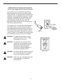
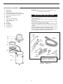
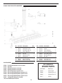
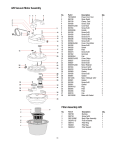
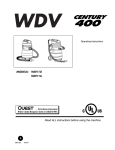
WET/DRY VACUUMS
POLYETHYLENE, POLYPROPYLENE & STEEL
MODELS:
315P
415P
429P
415S
415ST
415PLT
429ST
OPERATIONS AND PARTS MANUAL
IMPORTANT! READ THIS MANUAL PRIOR TO USE.
TABLE OF CONTENTS
Page No.
Important Safety Instructions . . . . . . . . . . . . . . . . . . . . . .1-3
Vacuum and Accessories . . . . . . . . . . . . . . . . . . . . . . . . . .4
Operation . . . . . . . . . . . . . . . . . . . . . . . . . . . . . . . . . . . . . .5
Wiring Diagram . . . . . . . . . . . . . . . . . . . . . . . . . . . . . . . . . .5
Daily Maintenance . . . . . . . . . . . . . . . . . . . . . . . . . . . . . . .5
Periodic Maintenance . . . . . . . . . . . . . . . . . . . . . . . . . . . . .6
Servicing the Filter and Vac Motor . . . . . . . . . . . . . . . . . .6-7
Vacuum Parts Diagram . . . . . . . . . . . . . . . . . . . . . . . . . .8-13
Accessories . . . . . . . . . . . . . . . . . . . . . . . . . . . . . . . . . . . .14
IMPORTANT SAFETY INSTRUCTIONS
When using an electrical appliance, basic precaution must
always be followed, including the following:
READ ALL INSTRUCTIONS BEFORE USING THIS MACHINE.
This machine is for commercial use.
WARNING
DANGER:
!
!
Failure to read and observe all DANGER statements could result in severe bodily injury or
death. Read and observe all DANGER statements found in your Owner’s Manual and on
your machine.
WARNING: Failure to read and observe all WARNING statements could result in injury to you or to
other personnel; property damage could occur as well. Read and observe all WARNING
statements found in your Owner’s Manual and on your machine.
CAUTION:
Failure to read and observe all CAUTION statements could result in damage to the
machine or to other property. Read and observe all CAUTION statements found in your
Owner’s Manual and on your machine.
DANGER:
Failure to read the Owner’s Manual prior to operating or attempting any service or
maintenance procedure to your machine could result in injury to you or to other personnel;
damage to the machine or to other property could occur as well. You must have training in
the operation of this machine before using it. If you or your operator(s) cannot read
English, have this manual explained fully before attempting to operate this machine.
DANGER:
Operating a machine that is not completely or fully assembled could result in injury or
property damage. Do not operate this machine until it is completely assembled. Inspect
the machine carefully before operation. Use only as described in this manual. Use only
the manufacturer’s recommended attachments.
DANGER:
Machines can cause an explosion when operated near flammable materials and vapors.
Do not use this machine with or near fuels, grain dust, solvents, thinners, or other
flammable materials.
!
DANGER:
Do not pick up flammable fluids, dust or vapors.
!
DANGER:
Do not vacuum anything that is burning or smoking, such as cigarettes, matches, or hot ashes.
!
DANGER:
This machine is not suitable for picking up health endangering dust.
!
DANGER:
Using a machine with a damaged power cord could result in an electrocution. Do not use
the machine if the power cord is damaged. Do not use the electrical cord to move the
machine. Keep cord away from heated surfaces. Do not unplug by pulling on the cord;
grasp the plug, not the cord. Turn off all controls before unplugging. Do not close a door
on cord or pull around sharp edges or corners.
!
!
!
!
1
!
!
DANGER:
Electrocution could occur if maintenance and repairs are performed on a unit that is not
properly disconnected from the power source. Disconnect the power supply before
attempting any maintenance or service.
WARNING: Operating a machine without observing all labels, decals, etc., could result in injury or
damage. Read all machine labels before attempting to operate the machine. Make sure
all of the labels are attached or fastened to the machine. Get replacement labels and
decals from the manufacturer’s distributor.
!
WARNING: Electrical components can “short-out” if exposed to water or moisture. Keep the electrical
components of the machine dry. Always store the machine in a dry area.
!
WARNING: Use of this machine to move other objects or to climb on could result in injury to the
operator or damage to the machine. Do not use this machine as a step or furniture. Do
not allow to be used as a toy. Close attention is necessary when used by or near children.
!
WARNING: Moving parts of this machine can cause injury and/or damage. Keep hands, feet, loose
clothing, hair, fingers, and all parts of the body away from openings and moving parts.
!
WARNING: Electrocution could occur if you handle the plug or appliance with wet hands. Do not
handle plug or appliance with wet hands.
!
WARNING: The machine employs a removable float for wet pick-up operation to reduce risk of
electric shock. Always install float before any wet pick-up operation.
!
WARNING: Rotating fan blades inside the cover. Before opening cover, switch off machine. Wait until
the fan/brush stops completely or dust and debris may be ejected.
!
WARNING: If the machine is not working properly, has been dropped, damaged, left outdoors, or
dropped into water, return it to an Authorized service center.
!
WARNING: Damage could occur to machine if openings are blocked. Do not put any object into
openings. Do not use with any opening blocked; keep free of dust, lint, hair, and anything
that may reduce air flow.
!
WARNING: Injury could occur to the operator or the machine if used without the dust bag and/or
filters. Do not use the machine without the dust bag and/or filters in place.
!
WARNING: Injury to the operator and/or damage to the machine could occur when cleaning on stairs,
unless extra caution is used. Use extra caution when cleaning on stairs.
!
WARNING: To reduce the risk of electrical shock, always use a 3-wire electrical system connected to
the electrical ground. Whenever possible connect the machine to an outlet protected by a
ground fault interrupter (GFCI). See “Grounding Instructions.”
SAVE THESE INSTRUCTIONS
2
120 Volt Machine Instructions For Connection
To The Power Supply And The Electrical Ground
This machine must be connected to the electrical
ground to protect the operator from electric shock.
The machine has an approved power cord with three
conductors and a plug with three terminals. Connect
the plug to a receptacle that has three holes and is
connected to the electrical ground. The green (or
green and yellow) conductor in the cord is the
ground wire. Never connect this wire to any terminal
other than the ground terminal.
This machine uses a 120 volt AC 60 cycle electrical
circuit. Make sure you have the correct frequency
and voltage before connecting the power cord to an
outlet. The machine has a plug as shown in Figure 1.
If a receptacle connected to the electrical ground as
shown in Figure 1 is not available, have one installed
by an electrical contractor. Do not use an adapter.
!
!
PLATE
SCREW
OUTLET
MUST BE
CONNECTED TO
THE ELECTRICAL
GROUND
GROUND PIN
WARNING: To reduce the risk of electric shock,
protect the machine from rain. Keep
the machine in a dry area.
WARNING: To reduce the risk of electric shock,
always use a 3-wire electrical system
connected to the electrical ground.
Whenever possible connect the
machine to an outlet protected by a
ground fault interrupter (GFCI).
!
WARNING: Do not cut, remove or break the ground
pin. If the outlet does not fit the plug,
consult your electrical contractor.
!
WARNING: Have worn, cut or damaged cords and
plugs replaced by an authorized
service person.
3
GFCI Outlet
VACUUM AND ACCESSORIES
A
B
C
D
E
F
G
H
I
J
K
M
N
O
P
Motor Block
On/Off Switch
Float: Keeps liquid out of Motor Block
Polyester Filter: Remove for use with liquids
Hooks: Secure Motor Block to Tank
Suction Inlet
Tank
1-pc. Hose End, Bent PVC
Hose, 10-ft. x 1-1/2" Flexible
1-pc PVC Wand (2)
Adapter
Dust Brush
Crevice Tool
Floor Brush, 16"
Squeegee, 16"
ATTENTION: The Polyester Filter must be cleaned after each
use to maintain efficient suction.
IMPORTANT INSTRUCTIONS
• Before use, the equipment must be correctly assembled with
all its components.
• Check that electrical outlet is correct for use with the plug on
the machine.
• Before connecting, check that the specified motor voltage
corresponds to the main voltage available.
• Never use the equipment near inflammable, explosive or toxic
substances: sparks from the motor could cause dangerous
reactions.
• Always unplug the machine from electrical outlet when leaving
machine unattended or before attempting any repair.
• Service and repair should be done by qualified personnel only.
Use only original manufacturer’s replacement parts.
H
(S76389)
I
(S70008)
J
(S76387)
K
(S76388)
O
(S76384)
M
(S76295)
P
(S76385)
N
(S70003)
S72672
Complete Standard Tool Kit
includes H, I, J, K, M, N, O and P.
S76386
4
Carpet Tool
OPERATION
This machine is a commercial vacuum designed for wet and
dry pick-up. The dual vac motors can be run together or
separately as the job requires.
DUAL SWITCHES
Dry soil can be vacuumed directly into the tank. To empty the
tank of dry soil, remove the top and dump into trash
receptacle.
Dual Vacuum
For wet pick-up, remove polyester filter. The machine is
equipped with a float shut-off. As the tank is filled to capacity,
a float rises and seals the vac intake, causing loss of vacuum.
Switch off the vacuum when this happens and bring the
machine to a floor drain.
Single Vacuum
Use the convenient drain hose at the back of the vacuum to
empty the tank.
With both wet and dry applications be sure to frequently clean
the filter. This is especially true when the vacuum is being
used with strippers and wax.
L
N
DAILY MAINTENANCE
Caution: Strippers and some detergents produce foam
which will damage the vac motors. The vac shut-off may
not be sensitive to all foams. Be sure to check that the
tank is not filling with foam. Use a defoaming agent to
avoid pulling foam through vac motor. Should vac motor
become wet, remove source of overflow and immediately
run vac motor open to dry.
At the end of each working day:
1
ELECTRIC DRAWING
1 – terminal block
2 – switch
3 – motor
2
1.
After each use, rinse tank with fresh water.
Periodically inspect the recovery tank and
decontaminate if necessary, using a Hospital Grade
Virucide or a 1:10 bleach to water solution. Waste
water should be disposed of properly.
2.
Remove head assembly and allow tank to dry.
3.
Remove filters for cleaning or to allow to dry.
4.
Inspect hoses for wear. Frayed or cracked hoses
should be replaced to avoid vacuum loss.
5.
Inspect power cord for wear. This cable will lay on wet
surfaces. To prevent electrical shock replace cords with
frayed or cracked insulation immediately.
5
3
PERIODIC MAINTENANCE
(Every six to twelve months):
1.
Check filter for wear, replace dirt saturated filters that
do not respond to normal cleaning.
2.
Inspect gasket seals and replace those which have
begun to leak.
3.
Examine carbon motor brushes and commutator.
Replace both carbon
brushes when either is
less than 3/8" long. (PN S8TOEG845)
SERVICING THE FILTER
The filter is accessed by lifting the head assembly off the tank.
Polyester filter is easily removed by simply lifting the filter basket out of the tank.
Cartridge filters – Remove the filter retainer by turning the black knob 90 degrees counter-clockwise.
Cartridge filter will then slide off of float assembly.
NOTE:
Be sure to frequently clean the filter.
Allow filter to dry after being used for wet pick-up.
Filters used for wet pick-up including stripper must be thoroughly cleaned before being allowed to dry.
Worn filters can affect vacuum performance. Replace the filter when it becomes worn out and normal cleaning
will not restore vac performance.
SERVICING THE VAC MOTOR
MOTOR REPLACEMENT
1.
Disconnect power cord from power source.
2.
To access the vac motor, remove the screws that attach the main cover to the head assembly and set
the cover to one side.
3.
Disconnect the motor’s 2 red lead wires from the main switch.
4.
Disconnect green/yellow wire by removing screw from motor core.
5.
Remove the four motor mounting screws.
6.
Remove motor plate and set aside.
7.
Take out the motor and remove the upper and lower gaskets.
8.
Inspect gaskets. If they shown any wear or tear in the material, replace.
9.
Install gaskets onto new motor. Make sure gaskets are properly seated.
10.
Install the new motor. Make sure foam mufflers are positioned properly.
11.
Attach motor plate to motor.
12.
Connect green/yellow wire to motor core.
13.
Connect motor’s 2 red lead wires to main switch.
14.
Re-assemble vac cover.
15.
Test for proper operation.
6
SERVICING THE VAC MOTOR
CARBON BRUSH REPLACEMENT
1.
Disconnect power cord from power source.
2.
To access the vac motor, remove the
screws that attach the main cover to the
head assembly and set the cover to one
side.
3.
Remove the motor cover by removing two
screws. See Figure 1
4.
Remove the wire terminal from carbon
brush housing. See Figure 2
5.
Remove the carbon brush assembly by
removing the 2 screws that attach it to the
vac motor. See Figure 3
6.
Inspect armature commutator. If it is
extremely pitted, grooved or not concentric
then the motor will need to be replaced or
sent to a qualified service center.
7.
Slide the yellow brush housing from plastic
holder. See Figure 4
8.
Reverse steps 7 through 4 to install new
brush and housing (part number
S8TOEG845)
9.
Repeat steps 4 through 8 for the other
carbon brush.
10.
Reverse steps 3 and 2 for re-assembly.
11.
Test for proper operation
Fig. 1
Fig. 2
Fig. 3
Fig. 4
7
315 VACUUM MOTOR ASSEMBLY
No.
Part Num.
Description
1.
2.
3.
4.
5.
6.
7.
8.
9.
10.
11.
12.
13.
14.
15.
16.
17.
18.
19.
20.
21.
22.
23.
24.
25.
S80326
S81006
S81006
S80140
S81006
S82992
S81152
S80138
S81122
S81006
S80139
S83937
S81146
S83969
S81006
S81005
S83900
S83608AU
S83901
S81024
S81064
S81120S
S83901
S83866
S80120
Switch, ON/OFF
Screw, 5 x 20
Screw, 5 x 20
Terminal Block
Screw, 5 x 20
Handle, Lift
Qty.
1
5
2
1
4
1
1
1
1
2
1
Strain Relief, Black
Cord
Screw, 5 x 20
Clamp, Cord
Filter
Cover, Dome
Gasket, Motor Exhaust
Screw, 5 x 20
Screw, 5 x 14
Filter
Motor Support
Motor Gasket
Washer, M4
Screw, M4 x 8
Motor, 1000W, 120V/60Hz
Motor Gasket
Disk, Noise Reduction
Base, Black, with Gasket
1
1
4
2
1
1
1
1
1
1
1
1
1
315 FILTER GROUP
No.
1.
2.
3.
4.
5.
6.
7.
8.
315 TANK ASSEMBLY
No.
Part Num.
Description
1.
2.
3.
4.
5.
6.
7.
8.
9.
10.
11.
12.
S82221
S82028
S81302
S81847
S81026
S82846
S82585
S82608
S82593
S82594
S82583
S82008
S82680
Complete Tank
Tank
Rivet, 5 x 19
Clamp
Screw, 5 x 30
Gasket
Retainer
Spring
Deflector
Push Button
Hose Adapter
Caster
Screw, M4 x 15
Qty.
1
1
4
2
4
1
1
1
1
1
1
4
16
8
Part Num. Description
S83706
S83724
S82823
S83138
S82676
S80123
S82860
S82859
Bushing, Ø8
Screw, 5 x 25
Body, Float
Filter, Strainer
Float
Ring, Filter
Filter Bag
Support, Filter Bag
Qty.
4
4
1
1
1
1
1
1
415 VACUUM MOTOR ASSEMBLY
No.
1.
2.
3.
4.
5.
6.
7.
8.
9.
10.
11.
12.
13.
14.
15.
16.
17.
18.
19.
20.
21.
22.
23.
24.
25.
26.
27.
28.
29.
30.
Part Num. Description
S81006
S81150
S82992
S81006
S80139
S80138
S81122
T82102005
S81006
S81005
S80508
S83383
S81050
S81130
S81135
S80326
S81026
S81006
S81006
S80464AU
S83969
S83901
S81024
S81064
S81120S
S83901
S83901
S83451
S83454
S83456
S83519
S80488
Screw, 5 x 20
Cover, Dome
Handle
Screw, 5 x 20
Clamp, Cord
Strain Relief
Power Cord, Single Motor
Power Cord, Dual Motor
Screw, 5 x 20
Screw, 5 x 14
Terminal Block
Cap
Screw, 5 x 35
Cover, Single Motor
Cover, Dual Motor
Switch, On/Off
Screw, 5 x 30
Screw, 5 x 20
Screw, 5 x 20
Motor Base
Gasket
Gasket
Washer, M4
Screw, M4 x 8
Motor, 1000W, 120V/60Hz
Gasket
Gasket
Plug
Filter
Filter
Cap
Base with Gasket
Qty.
6
1
1
2
1
1
1
2
2
1
2
7
1
1
1
4
8
1
3
1
1
1
1
1
2
2
3
3
2
1
415 FILTER GROUP
No.
Part Num. Description
1.
2.
3.
4.
5.
6.
7.
8.
9.
10.
S83706
S83724
S82823
S83117
S82676
S80473
S82845
S82833
S82852
S82855
Bushing
Screw, 5x25
Body, Filter Support
Strainer
Float
Filter Ring
Filter Bag
Support, Filter
Filter – OPTIONAL
Filter Retainer – OPTIONAL
Qty.
4
4
1
1
1
1
1
1
1
1
9
415P TANK ASSEMBLY
No.
Part Num.
Description
1.
2.
3.
4.
5.
6.
7.
8.
9.
10.
11.
12.
13.
14.
15.
16.
17.
S82615
S82558
S82637
S81026
S82584
S82846
S82593
S82652A
S81300
S81847
S81050
S83883
S81072
S81860
S81302
S82559
S82680
S82556
Complete Tank
Handle
Tank
Screw, 5x30
Retainer, Tank
Gasket
Deflector
Adapter, Hose
Rivet, 5 x 24.5
Clamp, Tank
Screw, 5 x 35
Plastic Washer
Support, Handle
Support, Handle
Rivet, 5 x 19
Caster
Screw, 4 x 15
Support, Axle
Qty.
No.
Part Num.
Description
2
1
1
4
1
1
1
1
4
2
8
8
2
2
2
2
8
2
18.
19.
20.
21.
22.
23.
24.
25.
26.
27.
28.
29.
30.
31.
32.
33.
34.
S80904
S82557
S83835
S82607
S81006
S82555
S80834
S80256
S82763
S83308
S82765
S83156
S82788
S82812
S82764
S86250
S82594
Wheel, Ø200
Cap, End
Cap, Axle
Spacer, Wheel
Screw, 5 x 20
Axle
Nut, Flange
Gasket
Elbow
Clamp
Drain Tube
Screw, 5 x 20
Clip Tube
Strap, Plug
Plug, Hose
Handgrip
Push Button, Two-Piece, Red
10
Qty.
2
2
2
2
8
1
1
1
1
1
1
1
1
1
1
2
1
415ST TANK ASSEMBLY
No.
Part Num.
Description
1.
2.
3.
4.
5.
6.
7.
8.
9.
10.
11.
12.
S82993
S81847
S81302
S83629
S83883
S83253
S81026
S82586
S82846
S82593
S82583
S82594
Handle
Clamp, Tank
Rivet, 5 x 19
Screw, 5 x 25
Washer
Tank – Steel
Screw, 5 x 30
Adapter, Tank
Gasket
Deflector
Adapter, Hose
Button
Qty.
No.
Part Num.
Description
2
2
4
4
4
1
4
1
1
1
1
1
13.
14.
15.
16.
17.
18.
19.
20.
21.
S82608
S82993
S82974
S83629
S83156
S83883
S82968
S82970
S82969
Spring
Handle
Washer
Screw, 5 x 25
Screw, 5 x 25
Washer
Hook, Tank
Swivel
Knob, Release
Qty.
1
1
2
2
4
4
1
2
2
415ST CART
11
No.
Part Num.
Description
1.
2.
3.
4.
5.
6.
7.
8.
9.
10.
11.
S83250
S80976
S82557
S80904
S83835
S81012
S80478
S80479
S81979
S83450
S86250
Cart
Plug
Cap, End
Wheel
Cap
Washer
Nut
Wheel, Front
Screw, 5 x 25
Clip Pad
Hand Grip
Qty.
1
2
2
2
2
2
2
2
4
4
2
415S TANK ASSEMBLY
No.
Part Num.
Description
1.
2.
3.
4.
5.
6.
7.
8.
9.
10.
11.
12.
13.
S82993
S81847
S81302
S83629
S83883
S80476
S81026
S82586
S82846
S82593
S82583
S82594
S82608
Handle
Clamp, Tank
Rivet, 5 x 19
Screw, 5 x 25
Washer
Tank
Screw, 5 x 30
Adapter, Tank
Gasket
Deflector
Adapter, Hose
Button
Spring
Qty.
2
2
4
4
4
1
4
1
1
1
1
1
415S CART
12
No.
Part Num.
Description
1.
2.
3.
4.
5.
6.
7.
8.
9.
10.
11.
12.
13.
14.
15.
16.
17.
18.
19.
20.
S80918
S80917
S80913
S81301
S80902
S80914
S81402
S81403
S81301
S80901
S80915
S81028
S80904
S81401
S82052
S81301
S80479
S81012
S80478
S86250
Handle, Cart
Support, Handle
T-tube
Rivet, 5 x 11
Block
Hand Wheel, M8 x 60
Spring
Plate, Threaded
Rivet, 5 x 11
Base, Cart
Screw, 12 x 140
Washer, M12
Wheel
Bushing
Spacer
Rivet, 5 x 11
Wheel
Washer
Nut, M10
Hand Grip
Qty.
1
2
2
2
1
1
1
1
2
1
2
2
2
2
2
2
2
6
2
2
415PLT TANK ASSEMBLY
No.
Part Num.
Description
1.
2.
3.
4.
5.
6.
7.
8.
9.
10.
11.
12.
S81847
S81300
S83773
S81026
S82586
S82846
S82593
S82583
S82594
S82608
S83771
S82993
Clamp, Tank
Rivet, 5 x 24.5
Tank
Screw, 5 x 30
Adapter, Tank
Gasket
Deflector, Tank
Adapter, Hose
Button, Hose
Spring
Bumper
Handle
Qty.
No.
Part Num.
Description
2
4
1
4
1
1
1
1
1
1
1
1
13.
14.
15.
16.
17.
S83883
S81026
S81026
S83883
S82172
Washer, Plastic
Screw, 5 x 30
Screw, 5 x 30
Washer, Plastic
Hook, Tank
Qty.
2
2
4
4
1
415PLT CART
13
No.
Part Num.
Description
1.
2.
3.
4.
5.
6.
7.
8.
9.
10.
11.
12.
13.
14.
15.
16.
17.
18.
19.
20.
21.
S82053
S82607
S82173
S81979
S83725
S83751
S83694
S83835
S82557
S80904
S82607
S82980
S83752
S81026
S82967
S81050
S82974
S82627
S81006
S82559
S83797
Spring
Spacer
Lock, Plastic
Screw, 5 x 25
Clamp
Shaft
Handle
Cap, Axle
Cap, End
Wheel
Spacer
Spacer
Axle
Screw, 5 x 30
Support, Axle
Screw, 5 x 35
Washer
Screw, 5 x 40
Screw, 5 x 20
Caster
Base, Cart
Qty.
2
2
2
4
2
1
1
2
2
2
2
2
1
8
2
2
6
12
8
2
1
S70042 FRONT-MOUNTED SQUEEGEE
No.
Part Num. Description
1.
2.
3.
4.
5.
6.
7.
8.
9.
10.
11.
S82164
S82187
S82163
S83115
S82189
S81033
S81732
S86137
S82245
S86138
S81034
Handwheel, M8 x 45
Small Block, Fixed
Handwheel, M6 x 25
Plate, Adjustment
Driver Pivot
Nut, M8
Adjustment Knob
Spring, Ø40
Rear Squeegee
Wheel, AIF, Ø40
Washer, Plain, M8
Qty.
No.
Part Num. Description
1
1
1
1
1
2
2
2
1
2
1
12.
13.
14.
15.
16.
17.
18.
19.
20.
21.
22.
S82177
S82198
S82196
S82197
S81856
S80010
S82297
S81035
S81036
S81755
S81006
Qty.
Body, Wet Fix Tool
Spacer
Front Squeegee
Bracket, Squeegee
Screw, M4 x16
Hose, Wet Fix Tool
Mounting Bracket
Nut, M5
Washer, M5
Screw, M5 x 16
Screw, M5 x 20
1
2
1
2
16
1
1
4
4
4
4
ACCESSORIES
S70042
S72741
S82860
S82845
S82852*
S76061*
S82995*
S82881*
S82855
RECOMMENDED
Front Mounted Squeegee, for all 415 models
Paper Bag
Filter Bag, Standard for 315 model
Filter Bag, Standard for 415 model
Filter Cartridge, Paper, Optional for 415
Filter Cartridge, Washable Paper, Optional for 415
Filter Cartridge, HEPA Equivalent, Optional for 415
Filter Cartridge, HEPA Equivalent, Optional for 315
Cartridge Filter Retainer, for all models
SPARE PARTS
S8TOEG845 . . . . . . . Motor Brush
S80326 . . . . . . . . . . . Switch, On/Off
S82860 . . . . . . . . . . . Polyester Filter, 315
S82845 . . . . . . . . . . . Polyester Filter, 415
S83117 . . . . . . . . . . . Strainer
*also order S82855 Retainer with Filter
14
Warranty Policy
Limited Warranty
Eagle Power Products (EPP) warrants new cleaning equipment against defects in material and
workmanship under normal use and service to the original purchaser as detailed below.
10 Years
Subject to the conditions stated below, EPP warrants polyethylene tanks and housings to be
free from defects in materials and workmanship for a period of ten years.
3 Years
Subject to the conditions stated below, EPP warrants all automatic scrubber components to
be free from defects in materials and workmanship for a 3-year period. Parts replaced or
repaired are warranted for the remainder of the original warranty period.
1 Year
Subject to the conditions stated below, EPP warrants all other cleaning equipment
components to be free from defects in materials and workmanship for a 1-year period. Parts
replaced or repaired are warranted for the remainder of the original warranty period.
Batteries are prorated for one year.
EPP will furnish and charge for replacement parts, including transportation, to the original
owner through an EPP authorized service center. If the part is returned within 30 days and is
found defective, the owner will be credited for the cost of the replacement part including
shipping and handling.
Labor charges are covered for one year from the date of purchase if provided by an authorized
EPP ser vice center. Travel is covered for 90 days for battery operated equipment only.
Wear items exempt from warranty include belts, carbon brushes, power cords, wheels, pad
drivers, clutch plates, brushes, pads, handle grips, filters, screens, throttle cables, and squeegees.
This warranty shall not apply to failures caused by misuse or abuse, improper
maintenance as stated in the operation manuals, use of unauthorized repair parts, repairs
by other than an EPP authorized service center, and damage in transit.
EPP disclaims and denies any liability for any direct, indirect, special incidental or consequential
damage which may be suffered as a result of sale, delivery, servicing, use, loss of any product,
downtime, labor, freight, or other charges not expressly included herein.
Date Purchased:
Model Number:
Serial Number:
Please be sure to record this information. This information will be necessary for future warranty rclaims.
Eagle Power Products Sales and Service Provided by:
1174 Northland Drive Mendota Heights, MN 55120
651.686.5399 Fax 651.686.5695
www.eaglepower.com
2002 Eagle Power Products All rights reserved. T9022- Rev A-5/02