1
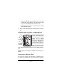
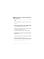
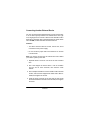
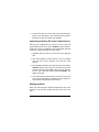
Please read before using this equipment. Owner’s Manual Invisible Beam Entry Alert WARNING: To reduce the risk of fire or shock hazard, do not expose this product to rain or moisture. CAUTION RISK OF ELECTRIC SHOCK. DO NOT OPEN. ! CAUTION: TO REDUCE THE RISK OF ELECTRIC SHOCK, DO NOT REMOVE COVER OR BACK. NO USER-SERVICEABLE PARTS INSIDE. REFER SERVICING TO QUALIFIED PERSONNEL. This symbol is intended to alert you to the presence of uninsulated dangerous voltage within the product’s enclosure that might be of sufficient magnitude to constitute a risk of electric shock. Do not open the product’s case. ! This symbol is intended to inform you that important operating and maintenance instructions are included in the literature accompanying this product. 2001 RadioShack Corporation All Rights Reserved. RadioShack and RadioShack.com are trademarks used by RadioShack Corporation 2 ˆ Contents Features ................................................................................. 4 General Information ......................................................... 5 Installation ............................................................................. 6 Choosing a Location ........................................................ 6 Connecting AC Power ..................................................... 7 Mounting the Alert ........................................................... 8 Mounting the Reflector .................................................... 9 Aligning the Beam ......................................................... 10 Adjusting Sensitivity ....................................................... 11 Connecting Optional Components ................................. 12 Connecting an External Siren ................................. 12 Connecting Another External Device ..................... 14 Connecting a Backup DC Power Limited Source ... 15 Routing the Wires ................................................... 15 Operation ............................................................................. Using the Alert ............................................................... Testing the Backup DC Source ...................................... Power Failure Alarm ...................................................... 16 16 16 17 Troubleshooting .................................................................. 17 Care ...................................................................................... 18 Replacing the Fuse ........................................................ 18 Lightning ........................................................................ 19 Specifications ..................................................................... 20 Contents 3 ˆ Features Your RadioShack Invisible Beam Entry Alert projects an invisible beam of infrared light across an area you want to secure. With your alert, you can easily detect an unauthorized entry through a doorway, window, or opening up to 50 feet wide. The alert includes a transmitter/sensor and a reflector. The transmitter sends out an invisible beam of infrared light which bounces off the reflector and returns to the sensor (if both units are aligned correctly). The infrared receiver generally does not detect room lights, indirect sunlight, or other light sources. If anything moves through the beam and interrupts its path, the alert triggers its built-in buzzer or activates a device connected to the Normally Open (N.O.) or Normally Closed (N.C.) terminals. The connected device can be an alarm sounding device, telephone dialer, or external alarm system. TEST/OFF Mode — lets you easily test the alert. ANNUNCIATE and ALARM Modes — let you set the alert to automatically sound the built-in buzzer or trigger an external siren or other device (such as a phone dialer or an alarm system) when the beam is interrupted. Sensitivity Control — lets you adjust how much activity will trigger the alarm. External Device Connection — includes a single 10–18 volt DC power output to provide power to an external security device. 4 Features Power Failure Alarm — triggers an external device when both AC power and a backup DC power limited source (if one is connected) are off. GENERAL INFORMATION Note: Some insurance companies provide a discount for homes protected by properly installed security and fire alarm systems. Check with your insurance carrier for requirements. Your Invisible Beam Entry Alert is designed to conform to federal regulations. To avoid problems, we urge you to read this manual completely before you install or use the alert. This alert is for indoor use only. This product is UL-listed to standard number UL639 for Intrusion Detection Units, and should only be used with UL-listed accessories. You need the following additional items (available at your local RadioShack store) to install a complete Invisible Beam Entry Alert system: • • • • External siren Phillips screwdriver Type CL2, 22-gauge wire 12-volt DC power limited source This manual helps you plan and select the required items. Your local RadioShack store carries additional security items you can use with the alert. Features 5 Caution: Home security systems require a permit in some areas. Check with your local law enforcement agency before you install your system. ˆ Installation CHOOSING A LOCATION This alert is designed for indoor operation only. The distance between the alert and the reflector should be between 2.7–50 feet. Position the alert on a desk or counter top, within 6 feet of an AC outlet. The outlet should always be on (not controlled by a wall switch) so the alert will not be accidentally turned off. Position the reflector so it correctly reflects the beam from the alert. If you cannot mount the reflector directly across from the 6 Installation alert, you can adjust the reflector angle up to 10° from center and adjust the beam lens up to 10° vertically and 5° horizontally. You can attach the reflector directly to a door so when the door is opened, the beam is interrupted. It is best to mount the alert and the reflector on parallel walls and at the same height, so the beam is aimed across a doorway or another opening. However, you can mount both units at different heights and then adjust the beam to compensate (see “Aligning the Beam” on Page 10). Notes: • The alert and reflector should be high enough to keep someone from easily stepping over the beam. • Avoid locations that will expose either the alert or the reflector to direct sunlight, which could cause false tripping or damage the alert. CONNECTING AC POWER 1. Loosen the screw on the door on the side of the alert, then open the door. 2. Press down on the top of the cover and remove it to expose the power jack. 3. Plug the supplied AC adapter’s barrel plug into the power jack at the side of the alert. Then plug the adapter into a standard AC outlet. Installation 7 MOUNTING THE ALERT You can mount the alert on a wall or on a desk using the supplied wood screws. Notes: • The supplied screws are suitable for wood surfaces only. If another type of surface is used, you might need other hardware. • Leave the cover off until after you have finished aligning the beam (see “Aligning the Beam” on Page 10). Before you mount the alert, loosen the screw on the door on the side of the alert, then open the door. Press down on the top of the cover and remove it to expose the screw holes. Set the mode switch on the alert to TEST/OFF. SENSITIVITY MODE Switch Follow these steps to mount the alert on a wall. 1. Using the alert as a template, mark the positions of the four screw holes at the selected wall location. 2. Drill four 3/32-inch holes in the marked positions. 3. Thread one of the supplied wood screws through each of the screw holes on the alert and into the mounting surface, then tighten the screws. 4. Plug the adapter into a standard AC outlet. 8 Installation Or, follow these steps to mount the alert on a desk. 1. Place the alert on a desk and use it as a template to mark the position of the two screw holes on the desk. 2. Drill two 3/32-inch holes in the marked positions. 3. Thread the two supplied wood screws through the holes on the alert and into the mounting surface, then tighten the screws. 4. Plug the adapter into a standard AC outlet. MOUNTING THE REFLECTOR Use the supplied mounting bracket, screws and adhesive strips to mount the reflector vertically or horizontally. 1. Using one half of the bracket as a template, mark the position of the two screw holes. 2. Drill two 3/32-inch holes in the marked positions. 3. Thread one of the supplied wood screws through each of the two screw holes in the bracket and into the mounting surface, then tighten the screws. Installation 9 4. Remove the protective paper from the adhesive strips on the back of the reflector and press the reflector onto the other half of the bracket. 5. Attach the half of the bracket with the reflector to the half you mounted on the wall in Step 3, using the two supplied machine screws with attached washers. Note: Do not tighten the machine screws until after you adjust the reflector’s angle (see “Adjusting Sensitivity” on Page 11). ALIGNING THE BEAM After you mount the alert and reflector, and connect power, you must make sure they are aligned correctly. 1. Check the angle adjustment by looking into the hole on the side of the alert’s mirror box, above the lens head. Note: If you cannot look into the hole on the mirror box from one side, slide the box out, turn it upside down, and reinstall it with the round hole facing toward the front. Then look into the mirror box from the other side. You can leave the mirror box in this position. If you do not see the reflector through the hole, you can adjust the reflector’s angle as much as 10° from the center position. Slightly tilt the reflector until it is at the desired angle, then tighten the screw. You can adjust the lens angle as much as 10° vertically and 5° horizontally. 10 Installation 2. Turn SENSITIVITY clockwise to MAX. If the alignment is correct, the ALIGNMENT INDICATOR lights. The indicator turns off when the beam is interrupted or when SENSIVITY is set to MIN. If the ALIGNMENT INDICATOR does not light, the alert and reflector are not aligned properly. Readjust the angles of the reflector and/or the alert’s lens. 3. Replace the front cover on the alert. ADJUSTING SENSITIVITY After you align the beam, adjust SENSITIVITY to ensure reliable performance and minimize the chance of false alarms. 1. Loosen the screw on the door on the side of the alert, then open the door to expose the sensitivity and mode switches. 2. Set the mode switch to TEST/OFF. 3. Turn SENSITIVITY counterclockwise to MIN. The ALIGNMENT INDICATOR turns off. 4. Turn SENSITIVITY clockwise until the ALIGNMENT INDICATOR lights. 5. With the mode switch still set to TEST/OFF, interrupt the beam by walking between the alert and the reflector. The ALIGNMENT INDICATOR turns off. Note: If you set SENSITIVITY too close to MAX: Installation 11 • The alert might not detect a broken beam if you walk near the alert. If this happens, walk away from the alert to see if the ALIGNMENT INDICATOR turns off. • The alert might not detect a person who is wearing highly reflective clothing. 6. When you are satisfied with the sensitivity setting, close the door. CONNECTING OPTIONAL COMPONENTS You can connect an external siren (or device which operN.C ates when the beam is interN.O rupted) and an optional backup DC power limited STANDBY source (as an alternate power source) to the alert’s terGND minals. Loosen the screw on EXT.DC the door on the side of the Power Jack alert and open the door. Press down on the top of the cover near the tab and remove the cover to expose the terminals. Fuse Caution: Set the mode switch to TEST/OFF before making connections. Connecting an External Siren Use Type CL2, 22-gauge wire to connect an external siren. If you connect an external siren to the alert and set the mode 12 Installation switch to ALARM, the external siren sounds when the beam path is interrupted. Caution: The external siren sounding device must be rated at 12 VDC, 0.5 A or less. 1. Separate about 2 inches of one end of the two-conductor wire. 2. Use a wire stripper to remove about 1/4 inch of insulation from the end of each conductor, then twist the loose strands. 3. Use a Phillips screwdriver to loosen the GND terminal screw. Then insert one of the conductors into the hole under the GND terminal and tighten the screw. 4. Insert the other conductor into the hole under the alert’s N.O terminal, then tighten the screw. 5. Connect the other end of the wire to the external siren. 6. Cut a 2-inch piece of wire and use a wire stripper to strip about 1/4 inch of insulation from both ends, then twist the loose strands. 7. Insert one of the wire ends into the hole under the terminal at the operating point of the alert’s relay (between N.C and N.O), then tighten the terminal’s screw. 8. Insert the other wire end into the hole under the alert’s positive (+) OUTPUT 10–18V DC 0.5A terminal (labeled EXT.DC), then tighten the terminal’s screw. Installation 13 Connecting Another External Device You can connect another external device (such as a phone dialer or an alarm system) instead of an external siren. Use Type CL2, 22-gauge wire to connect a device to the alert’s N.O or N.C terminals. If the beam path is interrupted with the mode switch set to ALARM, the alert activates the external device. Cautions: • The device must be rated at 12 VDC, 0.5A or less, and it must have its own power supply. • Do not connect a jumper wire to the OUTPUT 10–18 VDC 0.5A terminals. Note: You cannot connect both an external siren and a dialer (or an alarm system) to the alert. 1. Separate about 2 inches of one end of the two-conductor wire. 2. Use a wire stripper to remove about 1/4 inch of insulation from the end of each conductor, then twist the loose strands. 3. Use a Phillips screwdriver to loosen the N.O or N.C terminal screws, and insert the stripped ends under N.O or N.C terminals, then tighten the screws. 4. Insert the other conductor of the wire into the hole under the terminal between the N.O or N.C terminals, then tighten the screw. 14 Installation 5. Connect the other end of the wire to the external device. Refer to the instructions in the external device’s Owner’s Manual to confirm connections and operation. Connecting a Backup DC Power Limited Source Use type CL2, 22-gauge wire to connect a 12-volt 1-amp DC power limited source to the alert’s STANDBY terminal. When a backup DC source is installed, the alert automatically switches to DC source power during an AC power failure. 1. Separate about 2 inches of one end of the two-conductor wire. 2. Use a wire stripper to remove about 1/4 inch of insulation from the end of each conductor, then twist the loose strands. 3. Use a Phillips screwdriver to loosen the screw on the alert’s STANDBY terminal. Then insert one conductor into the hole under the terminal marked GND, insert the other conductor into the hole under the terminal marked STANDBY, and tighten the screws. 4. Connect the other end of the wire to the 12V DC source. Be sure to match the polarity, as indicated by the markings on the terminals of the alert and the DC source. Routing the Wires When you finish wiring the optional components to the screw terminals, route the wires through the slot at the side of the alert. Installation 15 ˆ Operation USING THE ALERT 1. Loosen the screw on the door on the side of the alert, then open the door to expose the sensitivity and mode switches. 2. Set the mode switch to ALARM or ANNC. When the beam is interrupted in the ALARM mode, the external siren sounds (or another external device is activated) until the path of the beam is restored. To silence the alarm sooner, set the mode switch to TEST/OFF. When the beam is interrupted in the ANNUNCIATE mode, the built-in buzzer sounds and the external siren (or other external device) is activated until the path of the beam is restored. 3. Close the door on the side of the alert and tighten the screw. TESTING THE BACKUP DC SOURCE 1. Set the mode switch to ALARM or ANNC. 2. Unplug the AC adapter from the AC outlet. 3. Interrupt the beam by walking between the alert and the reflector. 16 Operation 4. The built-in buzzer sounds and/or the external siren, dialer, or alarm system is activated. 5. To conserve the backup DC source’s power, set the mode switch to TEST/OFF as soon as you confirm proper operation. 6. Reconnect the AC adapter. POWER FAILURE ALARM When both AC power and the backup DC source are off, the alert triggers an external device (such as a phone dialer or an alarm system). ˆ Troubleshooting We do not expect you to have problems with your Invisible Beam Entry Alert, but if you do, refer to this table to find possible causes and remedies. If your alert is still not operating properly, take it to your local RadioShack store for assistance. Possible Cause Solution The external siren (or another connected device) does not operate. Problem The in-line fuse is blown. Replace the fuse with one of the same size and type (see “Replacing the Fuse” on Page 18). The alarm sounds when the infrared beam is not broken, giving off false alarms. The sensor is set out of range, causing it to operate erratically. Position the alert and the reflector within 3 to 50 feet of each other. Adjust SENSITIVITY so the false alarm stops. Troubleshooting 17 Problem Possible Cause Solution The reflector surface is Readjust and/or reposition the not set parallel to the front alert and/or reflector. of the alert. The sensor lenses are obscured with dust, lint, or other contaminants interfering with beam reception. Clean lenses using a nonabrasive lens cleaning solution and a lint-free cloth. ˆ Care Modifying or tampering with the alert’s internal components can cause a malfunction and might invalidate its warranty. If your alert is not performing as it should, take it to your local RadioShack store for assistance. REPLACING THE FUSE Check the fuse if the external siren (or another connected security device) is inoperative. If the fuse is blown, replace it with a fuse of the same size and type, rated at 0.5 A, 250V (available at your local RadioShack store). 1. Unplug the AC adapter and disconnect the backup DC source (if necessary). 2. Loosen the screw on the door on the side of the alert and open the door. 18 Care 3. Press down on the top of the cover near the tab, and remove the cover. Fuse Holder Fuse Ribbon 4. Remove the fuse by pulling the red ribbon. 5. If the fuse is blown, wrap the new fuse in the red ribbon and insert it in the fuse holder. 6. Plug in the AC adapter and reconnect the backup DC source (if one is used). 7. Replace the cover and tighten the screw. Warning: For continued protection against fire, replace only with the same type and rating of fuse. LIGHTNING Lightning damage is not common, but it can occur in electronic devices. A lightning strike near, or directly to, the power line may cause an excessive surge of voltage that can damage the alert. If you live in an area that has frequent or severe electrical storms, we suggest that you purchase a surge protector to help prevent damage to your alert as a result of power line surges. Your local RadioShack store has a wide selection of surge protectors. Care 19 ˆ Specifications Approximate Effective Distance ........................................................ 2.7 to 50 feet Beam Light Source ................................... Infrared LED (Pulse-Width Modulated) Receiver ......................................................... Infrared-Sensitive Photo-Transistor Indicators ..........................................................................................One Red LED Power Source ...................................................................... 120 VAC, 15W, 60 Hz Power Adapter ............................................................................. 12 VAC, 830 mA AC Input Terminals ..................................................................................... 12 VAC DC Input Terminals ............................................................................... 12 VDC 1A Unswitched Output Terminals (External Power) ...............................................10–18 VDC, 0.5 A Max., Resistive Alarm Relay Contact Switches ......................................................... N.O. and N.C. Alarm Relay Contact Capacity .......................................................... 12V DC 0.5A Circuit Protection ................................................................... 0.5 A, 250 VDC Fuse Dimension ..................................................................... 313/16 × 215/16× 29/16 inches (97.6 × 75.2 × 65.3 mm) Specifications are typical; individual units might vary. Specifications are subject to change and improvement without notice. Limited Ninety-Day Warranty This product is warranted by RadioShack against manufacturing defects in material and workmanship under normal use for ninety (90) days from the date of purchase from RadioShack company-owned stores and authorized RadioShack franchisees and dealers. EXCEPT AS PROVIDED HEREIN, RadioShack MAKES NO EXPRESS WARRANTIES AND ANY IMPLIED WARRANTIES, INCLUDING THOSE OF MERCHANTABILITY AND FITNESS FOR A PARTICULAR PURPOSE, ARE LIMITED IN DURATION TO THE DURATION OF THE WRITTEN LIMITED WARRANTIES CONTAINED HEREIN. EXCEPT AS PROVIDED HEREIN, RadioShack SHALL HAVE NO LIABILITY OR RESPONSIBILITY TO CUSTOMER OR ANY OTHER PERSON OR ENTITY WITH RESPECT TO ANY LIABILITY, LOSS OR DAMAGE CAUSED DIRECTLY OR INDIRECTLY BY USE OR PERFORMANCE OF THE PRODUCT OR ARISING OUT OF ANY BREACH OF THIS WARRANTY, INCLUDING, BUT NOT LIMITED TO, ANY DAMAGES RESULTING FROM INCONVENIENCE, LOSS OF TIME, DATA, PROPERTY, REVENUE, OR PROFIT OR ANY INDIRECT, SPECIAL, INCIDENTAL, OR CONSEQUENTIAL DAMAGES, EVEN IF RadioShack HAS BEEN ADVISED OF THE POSSIBILITY OF SUCH DAMAGES. Some states do not allow limitations on how long an implied warranty lasts or the exclusion or limitation of incidental or consequential damages, so the above limitations or exclusions may not apply to you. In the event of a product defect during the warranty period, take the product and the RadioShack sales receipt as proof of purchase date to any RadioShack store. RadioShack will, at its option, unless otherwise provided by law: (a) correct the defect by product repair without charge for parts and labor; (b) replace the product with one of the same or similar design; or (c) refund the purchase price. All replaced parts and products, and products on which a refund is made, become the property of RadioShack. New or reconditioned parts and products may be used in the performance of warranty service. Repaired or replaced parts and products are warranted for the remainder of the original warranty period. You will be charged for repair or replacement of the product made after the expiration of the warranty period. This warranty does not cover: (a) damage or failure caused by or attributable to acts of God, abuse, accident, misuse, improper or abnormal usage, failure to follow instructions, improper installation or maintenance, alteration, lightning or other incidence of excess voltage or current; (b) any repairs other than those provided by a RadioShack Authorized Service Facility; (c) consumables such as fuses or batteries; (d) cosmetic damage; (e) transportation, shipping or insurance costs; or (f) costs of product removal, installation, set-up service adjustment or reinstallation. This warranty gives you specific legal rights, and you may also have other rights which vary from state to state. RadioShack Customer Relations, 200 Taylor Street, 6th Floor, Fort Worth, TX 76102 We Service What We Sell 06A01 49-312 12/99 AO0054ABA1 Printed in China