1
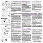
Cavitron SPS
®
™
Ultrasonic Scaler G98A
Installation and Service Manual
Please read carefully and completely before operating unit.
FORWARD
DENTSPLY® Professional is an ISO13485 registered company.
The DENTSPLY® Cavitron® SPS™ Scaler System is classified by Underwriters Laboratories Inc. with respect to electric shock,
fire, and mechanical hazards in accordance with UL 60601-1 and CSA C22.2 no. 601.1.
The Cavitron SPS Ultrasonic Scaler is equipped with a Sustained Performance System™ (SPS), which offers a constant balance
between scaling efficiency and patient comfort by maintaining the unit‘s power level when the insert tip encounters tenacious
deposits allowing the clinician to effectively scale even at a decreased/lower power setting.
The System operates by converting an SELV source current into high frequency current. The ultrasonic system consists of two parts: the handpiece/insert combination and the SPS™ electronic system. The SPS™ system incorporates two closed loops.
One loop provides automatic tuning (operating frequency is adjusted to be at resonance for each insert), the second loop
automatically controls the tip stroke over different working conditions. The DENTSPLY® Cavitron® SPS™ scaler produces 30,000
microscopically small strokes per second at the insert’s working tip. This, combined with acoustic effects of the coolant water,
produces a synergistic action that literally “powers away” the heaviest calculus deposits while providing exceptional operator and patient comfort.
TABLE OF CONTENTS
Specifications . . . . . . . . . . . . . . . . . . . . . . . . . . . . . . . . . .
Operating Conditions . . . . . . . . . . . . . . . . . . . . . . . . . . . . .
Storage & Shipping Conditions . . . . . . . . . . . . . . . . . . . . . . .
Classifications . . . . . . . . . . . . . . . . . . . . . . . . . . . . . . . . . .
Intended Use . . . . . . . . . . . . . . . . . . . . . . . . . . . . . . . . . . .
Technical Support . . . . . . . . . . . . . . . . . . . . . . . . . . . . . . .
Supplies & Replacement Parts . . . . . . . . . . . . . . . . . . . . . . . . .
Disposal of Unit . . . . . . . . . . . . . . . . . . . . . . . . . . . . . . . . .
WARRANTY . . . . . . . . . . . . . . . . . . . . . . . . . . . . . . . . . . . . 4
4
4
4
5
5
5
5
5
SECTION 1: Indications
1.1 Ultrasonic Procedures . . . . . . . . . . . . . . . . . . . . . . . . . . . . . . . . . 5
SECTION 2: contraindications & WARNINGS
2.1 Contraindications . . . . . . . . . . . . . . . . . . . . . . . . . . . . . . . . . . . . 5
2.2 Warnings . . . . . . . . . . . . . . . . . . . . . . . . . . . . . . . . . . . . . . . 5-6
SECTION 3: precautions
3.1 System Precautions . . . . . . . . . . . . . . . . . . . . . . . . . . . . . . . . . . . 6
3.2 Precautions for Ultrasonic Prophylaxis Procedures . . . . . . . . . . . . . . . . . . . 6
SECTION 4: INFECTION CONTROL
4.1 Infection Control Information Reference Booklet . . . . . . . . . . . . . . . . . . . . 6
4.2 General Infection Control Information . . . . . . . . . . . . . . . . . . . . . . . . . 6
4.3 Water Supply Recommendations . . . . . . . . . . . . . . . . . . . . . . . . . . . 6-7
SECTION 5: WATER LINE REQUIREMENTS . . . . . . . . . . . . . . . . . . . . 7
SECTION 6: INSTALLATION INSTRUCTIONS
6.1 Installation, Removal & Service Instructions . . . . . . . . . . . . . . . . . . . . . . 7
6.2 Post Installation Instruction Check . . . . . . . . . . . . . . . . . . . . . . . . . . 7-8
6.3 Installation Notes . . . . . . . . . . . . . . . . . . . . . . . . . . . . . . . . . . . . 8
6.4 Installation Templates . . . . . . . . . . . . . . . . . . . . . . . . . . . . . . . . . 9
6.5 Installation Diagram . . . . . . . . . . . . . . . . . . . . . . . . . . . . . . . . . 11
6.6 Installation and Operation Tables . . . . . . . . . . . . . . . . . . . . . . . . . . . 12
SECTION 7: CAVITRON® SPS™ ULTRASONIC SCALER SYSTEM DESCRIPTION
7.1 System Controls . . . . . . . . . . . . . . . . . . . . . . . . . . . . . . . . . . . 7.2 Steri-Mate™ Handpiece / Cable . . . . . . . . . . . . . . . . . . . . . . . . . . . 7.3 Cavitron® 30K Ultrasonic Inserts . . . . . . . . . . . . . . . . . . . . . . . . . . . 7.4 Foot Control and Operation . . . . . . . . . . . . . . . . . . . . . . . . . . . . . 13
14
15
15
SECTION 8: ACCESSORIES . . . . . . . . . . . . . . . . . . . . . . . . . . . . 16
SECTION 9: TECHNIQUES FOR USE
9.1 Patient Positioning . . . . . . . . . . . . . . . . . . . . . . . . . . . . . . . . . . 16
9.2 Performing Ultrasonic Scaling Procedures . . . . . . . . . . . . . . . . . . . . . . . 16
9.3 Patient Comfort Considerations . . . . . . . . . . . . . . . . . . . . . . . . . . . . 16
SECTION 10: SYSTEM CARE
10.1 Daily Protocol . . . . . . . . . . . . . . . . . . . . . . . . . . . . . . . . . . . . 17
SECTION 11: TROUBLESHOOTING & ANALYSIS / GUIDE . . . . . . . . . . 18-24
SECTION 12: SERVICE PARTS . . . . . . . . . . . . . . . . . . . . . . . . . 25-31
SPECIFICATIONS
Electrical Input
Pneumatic
Output Dimensions
Voltage
Current
Frequency
Power
Water Pressure
Water Temperature
Air Pressure (yellow line)
Air Pressure (orange line)
Frequency
Power
Water flow rate Height
Width
Length
Weight - Module
- Module w/cable +Steri-Mate
24 VAC SELV source
2.5 Amps
50/60 Hz
60 VA
25 – 60 psi (172 – 414 kPa)
41ºF – 77ºF (5ºC – 25ºC)
0 – 125 psi (0 – 862 kPa)
0 – 125 psi (0 – 862 kPa)
30 kHz nominal
3 – 30 watts
10 < flow < 60 ml/min
2.0 inches (5.1 cm)
3.7 inches (9.4 cm)
6.0 inches (15.3 cm)
24.0 ounces (694 g)
27.4 ounces (792 g)
OPERATING CONDITIONS
Ambient temperature: 15 – 40°C
Humidity: 30 – 75% RH
STORAGE AND SHIPPING CONDITIONS
Ambient temperature: -40°C – 70°C
Humidity: 10 – 95 RH (non-condensing)
Atmospheric pressure range: 7 – 15 psi (50 – 106 kPa)
CLASSIFICATIONS
Input Voltage Supplied by SELV power source
Degree of protection against electric shock
Type B
Degree of protection against harmful ingress of water Ordinary
Mode of operation
Continuous
Medical Device Directive Classification
IIa
Equipment is not suitable for use in the presence of flammable mixtures
Type B Equipment
OR
Footswitch IPX1
AC power (AC 24~)
Read Users Manual
Recognized by Underwriters Laboratories Inc. with respect to electric shock, fire, EMC and mechanical hazards only in accordance with UL 60601-1 and CSA C22.2 no. 601.1
4
intended use
Section 2:
Contraindications & Warnings
This product is intended for installation into an existing
dental handpiece delivery system. The end users are dental
professionals. The devices are used to debride light to heavy
calculus deposits from the tooth and root surfaces. Other
applications specialties include Periodontics, Orthodontics,
and Endodontics.
2.1 Contraindications
•
Ultrasonic Systems should not be used for restorative procedures involving condensation of amalgam.
•
For optimum performance use only with inserts manufactured by DENTSPLY Professional.
•
Persons fitted with cardiac pacemakers, defibrillators and other active implanted medical devices, have been cautioned that some types of electronic equipment might
interfere with the operation of the device. Although no instance of interference has ever been reported to DENTSPLY, we recommend that the handpiece and cables be kept at least 6 to 9 inches (15 to 23 cm) away from any device and their leads during use.
•
There are a variety of pacemakers and other medically implanted devices on the market. Clinicians should contact the device manufacturer or the patient’s physician for detailed information about the device.
Disposal of unit shall be in accordance with local regulations.
•
Dental Healthcare Professionals are responsible for reading the Directions for Use, understanding the capabilities of the Cavitron ultrasonic scaler and making appropriate choices for use of this instrument consistent with their knowledge, training, and experience.
Rx Only
•
Directions for use are not intended to advise Dental Healthcare Professionals on the practice of dentistry.
•
This product is designed to assist in eliminating susceptibility to retraction of oral fluids. To ensure adequate protection from cross-contamination from other devices connected to the Dental Unit, it is highly recommended that the Dental Unit be installed with anti-
retraction features. Additionally, the Dental Unit, including the anti-retraction features, must be properly maintained and periodically tested. For more information, please contact your Dental Unit manufacturer.
•
Failure to follow the recommendations for environmental operating conditions, including input water temperature, could result in injury to patients or users.
•
The use of High Volume Saliva Evacuation to reduce the quantity of aerosols released during treatment is highly recommended.
•
It is the responsibity of the Dental Healthcare Professional to determine the appropriate uses of this product and to understand the health of each patient, the dental procedures being undertaken, and industry and governmental agency recommendations, requirements, and regulations for safe practice of dentistry.
Technical Support
2.2 Warnings
For technical support and repair assistance in the U.S., SM
call a Cavitron Care representative at 1-800-989-8826 or 717-767-8502 Monday through Friday, 8:00 AM to
5:00 PM (Eastern Time). For other areas, contact your local DENTSPLY representative.
SupplieS &
Replacement Parts
To order supplies or replacement parts in the U.S., contact
your local DENTSPLY Professional Distributor or call 1-800-989-8826 or 717-767-8502, Monday through Friday,
8:00 A.M. to 5:00 P.M. (Eastern Time). For other areas,
contact your local DENTSPLY Professional Representative.
DISPOSAL OF UNIT
WARRANTY
The Cavitron® SPS™ G98 Ultrasonic Scaler is warranted
for TWO YEARS from date of purchase. The Steri-Mate
Handpiece enclosed with your system is warranted for SIX
MONTHS from date of purchase. Refer to the Warranty
Statement Sheet furnished with your system for full warranty
Statement and Terms.
Section 1:
Indications For Use
1.1 Ultrasonic Procedures
•
All general supra- and subgingival scaling applications.
•
Periodontal debridement for all types of periodontal diseases.
•
Endodontic procedures.
5
•
Where asepsis is required or deemed appropriate in the best professional judgement of the Dental Healthcare Professional, this product should not be used.
•
Water should be used for all scaling procedures. Water
flow is adjustable from less than 10 to greater than 60 ml per minute.
•
During boil-water advisories, this product should not be operated as an open water system (e.g. connected to a public water system). A Dental Healthcare Professional should disconnect the system from the central water source. The Cavitron DualSelect™ system can be attached to this unit and operated as a closed system until the advisory is cancelled. When the advisory is cancelled, flush all incoming waterlines from the public water system (e.g. faucets, waterlines and dental equipment) in accordance with the manufacturer‘s instructions for a minimum of 5 minutes.
•
The Cavitron unit works with Cavitron inserts as a system, and was designed and tested to deliver maximum performance for all currently available Cavitron and Cavitron Bellissima™ brand ultrasonic inserts. Companies that manufacture, repair or modify inserts carry the sole responsibility for proving the efficacy and performance of their products when used as a part of this system. Users are cautioned to understand the operating limits of their inserts before using in a clinical setting.
•
Prior to beginning treatment, patients should rinse with an antimicrobial such as Chlorhexidine Gluconate 0.12%. Rinsing with an antimicrobial reduces the chance of infection and reduces the number of microorganisms released in the form of aerosols during treatment.
•
Only adjust the system’s power adjustment knob with the insert outside the patients mouth.
Section 4:
Infection Control
Section 3:
Precautions
4.1 Infection Control Information
Reference Booklet
•
3.1 System Precautions
•
Equipment flushing and dental water supply system maintenance are strongly recommended.
•
Close manual shut-off valve on the dental office water supply every night before leaving the office.
•
The use of an in-line water filter is recommended.
•
Never operate system without fluid flowing through handpiece. 4.2 General Infection Control Information
3.2 Precautions for Ultrasonic
Prophylaxis Procedures
•
Like a toothbrush, ultrasonic inserts “wear out” with use. Inserts with just 2 mm of wear lose about 50% of their scaling efficiency. In general, it is recommended that ultrasonic inserts be discarded and replaced after 90 days, under normal use, to maintain optimal efficiency and avoid breakage. A Cavitron® Insert Efficiency Indicator is enclosed for your use. •
Discard the insert immediately if excessive wear is noted, or the insert shows signs of damage through mishandling.
•
Ultrasonic insert tips that have been bent, damaged, or reshaped are susceptible to in-use breakage and should be discarded and replaced immediately.
•
Retract the lips, cheeks, and tongue to prevent contact with the insert tip whenever it is placed in the patient’s mouth.
For your convenience, an Infection Control Information Reference Booklet has been included with your Cavitron® SPS™ System. Additional booklets can be obtained by calling Customer Service at 1-800-989-8826 or 717-767-8502 Monday through Friday, 8:00 AM to 5:00 PM (Eastern Time). For other areas, contact your local DENTSPLY representative. Insert sterilization information is included in each insert package.
•
Use standard personal protection equipment (i.e., wear face mask, eyewear, or face shield, gloves and protective gown).
•
For maximum operator and patient safety, carefully follow the Infection Control Information procedures detailed on the reference cards accompanying your System.
•
The combination of water and ultrasonic vibration will create aerosols. With proper technique, much of the aerosols can be effectively controlled and minimized. Please carefully follow the procedural guidelines regarding the use of your System.
•
It is highly recommended that all dental water supply systems conform to applicable CDC (Centers for Disease Control and Prevention) and ADA (American Dental Association) standards, and that all recommendations be followed in terms of flushing, and general infection control procedures. Knowledge 4.3 Water Supply Recommendations
6
of and compliance with agency guidelines, standards and recommendations is the sole responsibility of the Dental Healthcare Professional.
•
As a medical device, Cavitron® products need to be installed in accordance with local or national regulations, including guidelines for water quality (e.g. drinking water). As an open water system, such regulation may require your Cavitron product to be connected to a centralized water control device that prevents water containing contaminates from back-flow into the water supply. 2. Remove the cover of the Dental Control Unit.
3. Remove the mounting template from this manual and cut out as described (there are two templates).
4. Place the template on the bottom of the Dental Control Unit and position to mark the mounting holes.
5. Check to be sure the Cavitron module will be properly placed and that the power control is easily accessible.
6. Carefully mark and drill the mounting holes.
Section 5:
7. Invert the module, route the cable through the large diameter hole, align the two mounting studs and secure the module.
•
Incoming water supply line pressure to the ultrasonic scaler must be 25 psi (172kPa) minimum to 60 psi (414 kPa) maximum. If your dental water system's supply line pressure is above 60 psi, install a water pressure regulator on the water supply line to your Ultrasonic Scaler.
8. Locate the pilot air inside the Dental Control Unit, cut the tube and insert the tee fitting on the yellow adapter assembly in the mounting kit.
•
A manual shut-off valve on the dental water system supply line should be used so that the water can be completely shut-off when the office is unoccupied.
•
A filter in the dental water system supply line is recommended so that the particles in the water supply will be trapped before reaching the ultrasonic scaler.
•
After the above installations are complete on the dental water supply system, the dental office water line should be thoroughly flushed prior to connection to the ultrasonic system.
•
After flushing system verify there are no leaks.
Water Line Requirements
9. Secure all fittings with the supplied tubing retainers.
10.Secure the other end of the adapter assembly to the yellow tubing from the Cavitron module cable.
11.Secure the air line from the handpiece holder valve to the remaining barb on the adapter assembly.
12.Locate the input water line in the Dental Control Unit. Cut the line and insert and secure a small tee fitting.
13.Connect and secure the red tubing from the module cable to the remaining barb on the small tee fitting.
14.Locate the input drive air line in the Dental Control Unit. Cut line, insert and secure the large tee fitting.
15.Connect and secure the orange tubing from the Cavitron module cable to the remaining barb on the large tee fitting.
Section 6:
Installation Instructions
16.Connect the two (2) electrical wires from the module cable to the 24 VAC terminals in the Dental Control Unit.
6.1 Installation / Removal / Service
Instructions
17.The system is ready for post installation system check.
The Cavitron® SPS™ Integrated Scaler must be installed by a trained technician. The Installation Diagram shows all connections to the Dental Control Unit. The power source
must be a double insulated SELV-type device and qualified
to IEC 601.1. ALL POWER, WATER AND AIR INPUTS TO
THE DENTAL CONTROL UNIT MUST BE OFF DURING THE
INSTALLATION AND REMOVAL OF THE CAVITRON SYSTEM.
6.2 Post Installation Check
Turn on all water and air inputs to the Dental Control Unit.
Verify that all connections made during installation do not leak
and are secured with the supplied tubing retainers.
Preliminary Set-up
Installation: Purge the main water and air lines to the Dentral
Control Unit before connecting the Cavitron module.
1. Remove the Cavitron Ultrasonic Scaler, the handpiece cable assembly, Steri-Mate® handpiece, and mounting kit P/N 80918 from the shipping carton and set aside for mounting.
• Turn on the Dental Control Unit (refer to instruction manual).
• Set the power adjustment to the top of the Blue Zone.
7
• Plug the handpiece into the receptacle on the rear of the Cavitron module.
Performance Check: Power Boost (available
only with variable pressure foot controls)
• Connect Steri-Mate® handpiece to the cable connector assembly.
• Adjust power control on the Cavitron module to the top of the Blue Zone.
• Adjust the blue lavage control at the back of the handpiece to maximum (fully clockwise).
• Fully depress foot control and observe sound and spray.
Performance Check: Power and Lavage Flow
• Reduce pressure on the foot control until a change in spray and sound is noticeable.
• Activate foot control and purge the water system for 2 minutes.
• Vary pressure on the foot control to toggle between standard and boost modes.
• Hold the handpiece (without an insert installed) in an upright position over a sink or drain.
Installation Check: Interface Test
• Activate footswitch to fill the handpiece with water.
• Place handpiece in holder and depress foot control.
• Lubricate the rubber o-ring on the insert with water before placing it into the handpiece. Fully seat insert with a gentle push-twist motion. DO NOT FORCE.
• Verify Cavitron module does not activate.
• Inspect the inside of the Dental Control Unit and verify that all connections do not leak.
• Adjust the lavage control at the end of the handpiece for a moderate flow.
The Cavitron module has been successfully installed. Replace the cover to the Dental Control Unit.
• Verify operation by adjusting the power control between minimum and maximum on the Cavitron module and observe a change in the water spray.
6.3 Installation Notes
_____________________________________________________________________________
_____________________________________________________________________________
_____________________________________________________________________________
_____________________________________________________________________________
_____________________________________________________________________________
_____________________________________________________________________________
_____________________________________________________________________________
_____________________________________________________________________________
_____________________________________________________________________________
_____________________________________________________________________________
_____________________________________________________________________________
_____________________________________________________________________________
_____________________________________________________________________________
_____________________________________________________________________________
_____________________________________________________________________________
8
6.4 Installation Templates
9
Page 10 intentionally left blank -- back side of templates
6.5 Installation Diagram
11
6.6 Installation and Operation Tables
Cavitron SPS G-98A Connection
Dental Control Unit Head
BROWN & YELLOW WIRES
24 Volts AC Power
Connect to terminal strip.
24 Volt AC, 300 Watt Power Supply
RED TUBE
Scaler Water Supply
Tee into RED Control Block Manifold water tube
25–60 psi Water Supply
YELLOW TUBE
Handpiece Selection Pilot Air
Use installation tubing kit to Tee into YELLOW-RED
tube on Control Block Manifold – Pilot Air.
.005 Restrictor Barb installed in series.
Unused handpiece holder or handpiece whip
position required.
ORANGE TUBE
Foot Control Drive Air
Tee into ORANGE-BROWN tube on Control Block
Manifold – Drive Air.
SCALER 24 VAC POWER ACTIVATION – Yellow Tube
1. Cavitron Steri-Mate Scaler
Handpiece IN Holder.
2. Cavitron Steri-Mate Scaler
Handpiece whip RELEASED.
1. Cavitron Steri-Mate Scaler Handpiece selected and REMOVED from Holder.
2. Cavitron Steri-Mate Scaler Handpiece whip selected and PULLED FORWARD.
Scaler 24 VAC Power – OFF
Air–Electric switch – CIRCUIT OPEN
Scaler 24 VAC Power – ON
Air–Electric switch – CIRCUIT
CLOSED
1. >20 psi air pressure to Yellow tube. HP Holder Whisker valve sealed.
2. >20 psi air pressure to Yellow tube. Handpiece whip bleed valve sealed.
1. 2–20 psi air pressure to Yellow tube. HP Holder Whisker valve bleeds air pressure off.
2. 2–20 psi air pressure to Yellow tube. Handpiece whip bleed releases air pressure.
NORMAL & BOOST ULTRASONIC SCALING POWER – Orange Tube
Proportional Foot Control
depressed partially.
Cavitron SPS™ Ultrasonic scaling
power activated in NORMAL mode.
2–12 psi air pressure to Orange tube.
Dual Air-Electric Switch, S1 CLOSES
(S1 = Blue & Black Leads)
Proportional Foot Control
depressed to a lower position
or completely.
Cavitron SPS™ Ultrasonic scaling
power will switch from NORMAL
mode to BOOST mode.
Dual Air-Electric Switch, S1 and S2
CLOSE (S1 = Blue & Black Leads,
S2 = White & Black Leads)
12
40 – 80 psi air pressure to Orange tube.
Section 7: SPS™ Ultrasonic
Scaler System Description
7.1 System Controls
The Cavitron® SPS™ module is enabled whenever the
clinician removes the handpiece from the handpiece holder.
ON/OFF Function
The Ultrasonic scaling activation is switched ON and OFF
using the treatment unit‘s footswitch.
Power Adjustment
Turn knob to select ultrasonic power level for operation:
clockwise increases system power, counter clockwise
decreases system power.
The Blue Zone™ is an extended low-power range providing
effective subgingival debridement and greater patient comfort
during definitive therapy.
Foot Controlled Power Boost Function
A second position on the footswitch (fully depressed
footswitch) provides the capability to briefly increase the
unit’s power output for quick, efficient removal of tenacious
deposits using only the foot control without touching the unit.
TYPICAL INSTALLATION
Note: Foot controlled power boost function requires a
variable pressure/proportional footswitch.
Lavage Flow Adjustment
Water flow through the handpiece is adjusted by rotating a
control element on the cable connector (blue).
13
7.2 Steri-Mate Handpiece / Cable
The handpiece accepts all Cavitron® 30K™ Ultrasonic Inserts.
Handpiece Connector (Handpiece & Mating Assembly are Keyed)
Steri-Mate® Handpiece
Insert Port
Cable Assembly
Date Codes (MMYY)
Date Codes (MMYY)
Prior to connecting, align Handpiece and Cable
Assembly electrical connections. If Cable Assembly
does not seat into Handpiece, gently rotate handpiece until contacts align.
DO NOT TWIST WHILE PUSHING CONNECTOR INTO HANDPIECE.
AUTOCLAVE SYMBOL- Sterilizable up to temperature specified
BLUE Lavage Knob
Lavage Control
Turn the Lavage Control to select flow rate during
system operation. Clockwise increases flow at insert tip,
counterclockwise decreases flow. The flow rate through the
handpiece also determines the temperature of the lavage.
Lower flow rates produce warmer lavage. Higher flow rates
produce cooler lavage.
Steri-Mate®
Handpiece
If the handpiece becomes warm, increase the flow rate. With
experience, the Dental Healthcare Professional will be able to
determine the best flow rate setting for optimum operating
efficiency and patient comfort.
Swivel Feature
Reduces cable drag as handpiece rotates during procedures.
Steri-Mate Grip Accessory (not shown)
The Steri-Mate Grip provides an ergonomic and comfortable
grasp of the handpiece. The grip is sterilizable and is available
in several different colors as an accessory for your Steri-Mate
Handpiece. See installation instructions provided with the grip.
14
7.3 Cavitron® 30K™ Ultrasonic Inserts
The many styles of DENTSPLY Cavitron® Ultrasonic Inserts are easily interchangeable for various procedures and applications.
Connecting Body
Transfers and amplifies mechanical motion of the stack to insert tip.
O-Ring
Provides seal for handpiece coolant.
Insert Tip
Shape and size of tip
determine access and
adaptation. Preheated
lavage is directed to
the tip.
Magnetostrictive Stack
Converts energy provided by the handpiece into mechanical oscillations
used to activate the insert tip.
Finger Grip
Insert Marking
Manufacturer, Date (YDDD= single digit year and three digit day of year)
Frequency, and Type (e.g., DENTSPLY 7305 30K FSI-SLI-10S)
Hold the handpiece in an upright position. Depress footswitch to fill the handpiece with water. Lubricate the rubber O-Ring on
the insert with water before placing it into the handpiece. Fully seat insert with a gentle push-twist motion. DO NOT FORCE.
7.4 Foot Control Information & Operation
•
The Foot Control activates both ultrasonic energy and Lavage Flow at the insert tip. Lightly depressing the footswitch whenever the handpiece is removed from the handpiece holder will activate the ultrasonics and lavage flow.
•
A boost function is activated by fully depressing the footswitch. This feature is active in the low to mid range of the power control. The power level will return to the control setting when the footswitch is returned to it’s slightly depressed position. The momentary increase in power is indicated by a slight increase in noise level and a change in spray pattern.
•
Practicing outside the mouth is recommended for the operator to familarize themselves with the boost feature.
15
Section 8:
Accessories
•
Steri-Mate® Detachable Sterilizable Handpiece
•
Steri-Mate Handpiece Grips
•
Detachable Handpiece Cable Assembly with Swivel
•
Cavitron® Ultrasonic Inserts
®
Section 9:
Techniques For Use
•
In general, it is suggested that a “feather-light-touch” be used for ultrasonic scaling. The motion of the activated tip and acoustic effects of the irrigating fluid, in most cases, are adequate to remove even the most tenacious calculus.
•
Periodically check the Cavitron Ultrasonic Insert for wear with the Cavitron Insert Efficiency Indicator.
•
The use of a saliva ejector or High Volume Evacuator (HVE) is recommended during all procedures.
•
Set the system’s Power Level Control to the lowest efficient power setting for the application and the selected insert.
9.3 Patient Comfort Considerations
Reasons for sensitivity
9.1 Patient Positioning
•
Incorrect tip placement. Point should be directed away from root surfaces.
Not keeping the tip in motion on the tooth. Do not allow the insert to remain in a static position on any one area of the tooth. Change the insert’s path of motion.
•
The backrest of the chair should be adjusted for optimal access to both the upper and lower arches. This assures patient comfort and clinician visibility.
•
Have the patient turn head to the right or left.
•
•
Position chin up or down depending on the quadrant and surface being treated.
•
Applying excessive pressure. Use extremely light grasp and pressure, especially on exposed cementum.
•
Evacuate irrigant using either a saliva ejector or High Vacuum Evacuator (HVE).
•
If sensitivity persists, decrease power setting and/or move from the sensitive tooth to another and then return.
9.2 Performing Ultrasonic
Scaling Procedures
Note: Refer to the Infection Control Information
booklet supplied with your system for general
procedures to be followed at the beginning of
each day and between patients.
•
The edges of Cavitron® Ultrasonic Inserts are intentionally
rounded so there is minimal danger of tissue laceration with proper ultrasonic scaling techniques. Wherever the insert tip is placed in the patient‘s mouth, the lips, cheek and tongue should be retracted to prevent accidental (prolonged) contact with the activated tip.
•
Turn Power Level Control to select ultrasonic power level for operation. Clockwise increases system power. Power level will increase throughout the full range of the control. Hold the handpiece over a sink or drain. Press the foot control to activate the system. Check spray to verify fluid is reaching the working end of the insert tip. Adjust the Lavage Control to ensure adequate flow for the selected power setting. Greater flow settings provide cooler irrigation.
•
It may „be necessary to adjust lavage with the system in “Boost mode (Foot Control fully depressed) so adequate fluid will be available to cool tip to tooth interface.
16
Section 10: System Care
Shut-Down Procedures at the
end of the day:
It is recommended that you perform the following
maintenance procedures to help maximize water quality and
to be in compliance with CDC guidelines for infection control. 1.
2.
3.
4.
5.
6.
10.1 Daily Protocol
Start-Up Procedures at the
beginning of the day:
1.
2.
3.
4.
5.
6.
7.
Switch ON the dental treatment unit (refer to instruction manual of treatment unit).
Remove the Cavitron® cable connector assembly from handpiece holder and set power adjustment to top of Blue Zone.
Connect a sterilized Steri-Mate® handpiece to the cable connector assembly. (Refer to the Infection Control information booklet for sterilizing instructions.)
Adjust the lavage control to maximum.
Hold the handpiece (without an insert installed) over a sink or drain. Activate the foot control and flush water through handpiece for two minutes.
Place a sterilized insert into the handpiece using a gentle push-twist motion. (Refer to the Cavitron Ultrasonic Inserts Directions for use for cleaning and sterilizing instructions.)
Activate the ultrasonics and adjust the power and lavage control to your preferred operating positions.
1.
2.
3.
4.
5.
6.
Remove any ultrasonic inserts and the Steri-Mate® handpiece. Clean and sterilize the handpiece and all inserts used during the procedure. (Refer to the Infection Control Information booklet and the Cavitron Ultrasonic Inserts Directions for Use for cleaning and sterilizing instructions.)
Clean and disinfect the handpiece cable assembly by applying a water-based disinfectant solution*, carefully following the instructions provided by the solution manufacturer. To clean the cable, generously spray disinfectant solution on a clean towel and wipe the cable and connector. Discard used towel. To disinfect the system, generously spray disinfectant on a clean towel and wipe the cable and connector. Allow the disinfectant solution to air dry.
Clean and disinfect all surfaces of the dental treatment control head according to the manufacturer’s instructions.
Connect a sterilized Steri-Mate® handpiece onto its mating cable connector. Set power adjustment to top of the Blue Zone, adjust the lavage control to maximum.
Hold the handpiece (without an insert installed) over a sink or drain. Activate the foot control and flush water through handpiece for at least thirty seconds.
Place a sterilized insert into the handpiece.
Flush the Cavitron® ultrasonic system according to the dental treatment unit manufacturer’s instructions.
Remove any ultrasonic inserts and the Steri-Mate® handpiece. Clean and sterilize the handpiece and all inserts used during the procedure. (Refer to the Infection Control Information booklet and the Cavitron Ultrasonic Inserts Directions for Use for cleaning and sterilizing instructions.)
Clean and disinfect the handpiece cable assembly by applying a water-based disinfectant solution*, carefully following the instructions provided by the solution manufacturer. To clean the cable, generously spray disinfectant solution on a clean towel and wipe the cable and connector. Discard used towel. To disinfect the system, generously spray disinfectant on a clean towel and wipe the cable and connector. Allow the disinfectant solution to air dry.
Clean and disinfect all surfaces of the dental treatment control head according to the manufacturer’s instructions.
Place the cable connector into the handpiece holder for storage.
Turn OFF the power and water to the dental treatment unit.
*NOTE: Water-based disinfection solutions are
preferred. Some alcohol-based disinfectant
solutions may discolor the handpiece cable and
connector.
Between Patients:
17
Section 11: Troubleshooting and Analysis
18
Section 11: Troubleshooting and Analysis, continued
19
Section 11: Troubleshooting and Analysis, continued
20
Section 11: Troubleshooting Guide
This troubleshooting section is meant for use by qualified Cavitron® Service Technicians.
SYMPTOMS
Low insert scaling power or
insert stops vibrating when
contacting tooth surface.
CAUSES
CORRECTIVE MEASURES
1. Insert malfunction.
1. Test with another Cavitron® insert. If test insert works properly, discard the original insert.
2. Insert is not pushed in far enough 2. a. Check if insert is fully seated in the handpiece.
for automatic pick-up.
b. If a handpiece soft grip is being used, verify that the grip is flush with the hard plastic of the insert port. Refer to the Installation Instructions provided with the soft grip for correct installation.
3. Unit improperly calibrated.
3. a. Return scaler to DENTSPLY® for factory certified service.
b. Refer to DENTSPLY® Professional Division- Product Service SOP PS-00135.
Intermittent scaling power or no 1. Insert malfunction.
scaling power.
(continued on next page)
1. Test with another Cavitron® insert. If test insert works properly, discard the original insert.
2. Insert is not pushed in far enough 2. a. Check if insert is fully seated in the handpiece.
for automatic pick-up.
b. If a handpiece soft grip is being used, verify that the grip is flush with the hard plastic of the insert port. Refer to the Installation Instructions provided with the soft grip for correct installation.
3. Malfunction in Steri-Mate™ Handpiece.
3. Replace Steri-Mate™ Handpiece.
4. Bent or missing electrical pin in Steri-Mate™ Handpiece.
4. Replace Steri-Mate™ Handpiece.
5. Open or intermittent wires in handpiece cable assembly.
5. Install a working Steri-Mate™ Handpiece on the cable. Unplug the Handpiece cable connector at J3
of the Power Drive PC Board and check the continuity of the wires.
a. Connect the ohmmeter between RED-GRN wire terminals. Flex the handpiece cable and check the intermittent readings. If the ohmmeter reading is not consistent or it is indicating an open circuit, the handpiece cable assembly is likely to be damaged and should be replaced.
b. Connect the ohmmeter between WHT-GRN wire terminals and repeat the procedure above.
(continued on next page)
(continued on next page)
21
Section 11: Troubleshooting Guide, continued
This troubleshooting section is meant for use by qualified Cavitron® Service Technicians.
SYMPTOMS
CAUSES
CORRECTIVE MEASURES
Intermittent scaling power or no 6. Loose wiring or defective solder scaling power.
joint in the unit wiring.
6. Troubleshoot the unit wiring and connectors.
(Continued)
7. a. Verify 21.6 to 26.4 Volts AC supply to the unit.
7. No power to the unit.
b. Replace the Power Drive PC board.
Handpiece heats up.
8. Faulty Air Switch.
8. Replace the component.
1. Insufficient water to cool handpiece.
1. Increase the setting on the handpiece lavage control until handpiece runs cool.
2. Air trapped in the handpiece.
2. When the inserts are changed, hold the handpiece in an upright position until the trapped air is removed and the water flows properly.
3. Insert water passageway clogged. 3. Replace the Cavitron® insert and check operation.
4. Handpiece cable not supported during procedure.
4. Loop handpiece cable around arm or support with finger to prevent water restriction.
5. Worn insert being used.
5. Replace with a new Cavitron® insert. Worn inserts require higher power settings producing more heat.
22
Section 11: Troubleshooting Guide, continued
This troubleshooting section is meant for use by qualified Cavitron® Service Technicians.
SYMPTOMS
Insert vibrates but no water or
insufficient water flows from the
handpiece.
CAUSES
CORRECTIVE MEASURES
1. Low incoming dental office water 1. Measure water pressure at dental office.
pressure.
Adjust incoming source water pressure to specification. Water pressure should be 25-60 psi.
2. Improper setting of the water regulator.
2. Adjust the water regulator for 24 psi.
3. Handpiece cable water tubing and 3. Remove restriction if possible or replace wires twisted.
handpiece cable assembly.
4. Damaged handpiece cable Flow Control.
4. Replace handpiece cable assembly.
5. Obstruction or mineral deposits in 5. a. Remove the insert and turn the water valve
the water system in the unit.
full open. Observe the water flow. If the flow is good then the obstruction is in the insert.
b. If the obstruction is not in the insert, then
remove the handpiece water line at solenoid and check the water flow. If flow is good, then
the obstruction is in handpiece supply line.
Water spray from insert is not
properly covering the operating
area of the activated tip.
1. Improper water flow adjustment.
1. Refer to “Directions for Use for Cavitron® SPS™ „
Ultrasonic Scaler for instructions on water flow adjustment.
2. P-style insert water tube incorrectly aimed.
2. Use small smooth pliers, reposition the water tube and direct the spray at the back of the insert tip.
3. Insert is partially clogged.
3. Replace the insert.
Water drips from the handpiece
when not operating.
1. Water solenoid valve leaking due 1. Replace the water solenoid assembly.
to trapped debris.
Water leak from the handpiece
while in operation.
1. O-ring worn on insert.
1. Replace the O-ring with genuine Cavitron® O-rings. O-rings are available in packs of 12: Green O-Rings P/N 62605 Black O-Rings P/N 62351
2. Water leak in plastic water line at handpiece or inside the Steri-Mate™ Handpiece.
2. a. Unplug the Steri-Mate™ handpiece from the cable and replace the small O-ring on the connector. Part No. 79357 (12-Pack)
b. Replace the Steri-Mate™ handpiece and/or cable assembly.
23
Section 11: Troubleshooting Guide, continued
This troubleshooting section is meant for use by qualified Cavitron® Service Technicians.
SYMPTOMS
CAUSES
CORRECTIVE MEASURES
Water flow not controllable
by turning the handpiece flow
control knob.
1. Malfunction of water regulator.
1. Replace the water regulator assembly. Adjust the water regulator to 25 psi.
Inserts cannot be installed in
the handpiece properly.
1. O-ring on the insert is dry.
1. Lubricate the O-ring with water. If the O-ring is worn, replace it.
2. Incorrect or damaged O-ring installed on the insert.
2. Replace the insert O-ring with Cavitron® O-rings. O-rings are available in packs of 12: Green O-Rings P/N 62605 Black O-Rings P/N 62351
1. Verify unit operation.
1. Fully depress the foot control, slowly reduce pressure until a decrease in spray pattern is observed.
2. Power set too high.
2. Reduce the power setting below the mid-point and verify the operation.
3. Insert is damaged or worn.
3. Install a new Cavitron 30K insert and verify the operation.
4. Control unit drive air pressure is not varying.
4. Remove the orange tube and verify pressure changes from 0 to 80 psi while depressing the foot control.
5. Faulty air pressure switch.
5. Replace the component.
1. Faulty air switch.
1. Remove the yellow tube, if the air present, replace the handpiece holder switch.
2. Sticking or faulty whisker valve.
2. Repair the control unit.
Boost mode does not function.
Unit activates with the scaler
handpiece in the holder.
24
SECTION 12: Service Parts
2
5 2X
3 2X
2&)*.3:8&
24)*1,&
@
B;
(F[NYWTS858
:QYWFXTSNH8HFQJW
8#%«*\«#«8#
75«219'4««9#665
75«(4'3««-*\
1
(&:9.43
2X
4 2X
G98A Cavitron® Scaler Module Assembly
ITEM
1
2
3
4
5
QUANTITY
2
1
2
2
2
PART NO.
586037005
574247007
6297501
62852
594002020
DESCRIPTION
SCREW, COVER
SIL-PAD, PINK INSULATING
SCREW, SOLENOID
SCREW, PC BOARD MOUNTING
STANDOFF, HEX PC BOARD MOUNTING
25
28
SECTION 12: Service Parts, continued
6
1
3
&ª
5&9*39
;;
4
8*7.&134
B;
@
2&)*.3:8&
(F[NYWTS858
:QYWFXTSNH8HFQJW
24)*1,&
5
8#%«*\«#«8#«
75«219'4««9#665
75«(4'3««-*\
2
G98A Cavitron® Scaler Module Assembly
ITEM
1
2
3
4
5
6
QUANTITY
1
1
1
1
1
2
PART NO.
63770
562096001
61631
625036011
625036012
776030230
DESCRIPTION
CLIP, AIR SWITCH (LARGE)
CLIP, WATER REGULATOR (GREY)
TUBING, RED, .062" ID (PER FOOT)
TUBING, ORANGE, .062" ID (PER FOOT)
TUBING, YELLOW, .062" ID (PER FOOT)
CLIP, DUAL AIR SWITCH (SMALL)
26
29
SECTION 12: Service Parts, continued
WHITE
PIN 1
RED
GREEN
BLACK
BLUE
S2
S1
BLACK
BLACK
ITEM 1
BROWN
BROWN
1
2
ITEM 2
YELLOW
WHITE
WIRE
GREEN
WIRE
1
2
3
RED
TUBING
RED
WIRE
ITEM 3
G98A Cavitron® Scaler Harness Assemblies
ITEM
1
2
3
QUANTITY
1
1
1
PART NO.
80949
80950
80951
DESCRIPTION
CONTROL CABLE ASSEMBLY
POWER CABLE ASSEMBLY
HANDPIECE CABLE HARNESS
27
30
SECTION 12: Service Parts, continued
1
2
G98A Cavitron® Scaler Water Solenoid and Regulator
ITEM
1
2
QUANTITY
1
1
PART NO.
79924
629195002
DESCRIPTION
WATER SOLENOID ASSEMBLY (WITH FITTINGS)
WATER REGULATOR ASSEMBLY (WITH FITTINGS)
31
28
SECTION 12: Service Parts, continued
ITEM 1
ITEM 2
G98A Cavitron® Scaler PC Board Assemblies
ITEM
1
2
QUANTITY
1
1
PART NO.
81020-3
81101
DESCRIPTION
UNIVERSAL SPS CONTROL PC BOARD ASSEMBLY
POWER DRIVE PC BOARD ASSEMBLY
29
32
SECTION 12: Service Parts, continued
1
Power
3
CAVITRON
SPS
2
4
5
6
G98A Cavitron® Scaler Housing and Handpiece Assemblies
ITEM
1
2
3
QUANTITY
1
1
1
1
PART NO.
80502
80843
78688
78703
4
1
81279
81277
8127901
5
6
1
1
79357
776030267
DESCRIPTION
KNOB, MOLDED BLUE
COVER, DECORATED
30K STERI-MATETM HANDPIECE, DECORATED 1-PACK
30K STERI-MATETM HANDPIECE, DECORATED 3-PACK
4-FOOT HANDPIECE CABLE, DECORATED SURF WITH
SWIVEL AND FLOW CONTROL
6.5-FOOT HANDPIECE CABLE, DECORATED BLACK
WITH SWIVEL AND FLOW CONTROL
11-FOOT HANDPIECE CABLE, DECORATED SURF WITH
SWIVEL AND FLOW CONTROL
O-RING, STERI-MATETM HP CABLE, 12 PACK
O-RING, HANDPIECE PLUG
30
33
SECTION 12: Service Parts, continued
5
2
3
ITEM 1
4
G98A Cavitron® Scaler Installation Kit
ITEM
1
2
3
4
5
QUANTITY
1
2
1
3
12
1
3
3
3
PART NO.
80918
625036012
623068001
623067001
80777
623066001
562098001
587092001
588072010
DESCRIPTION
INSTALLATION KIT (W/UNIT MOUNTING HARDWARE)
TUBING, YELLOW, .062" ID (PER FOOT)
RESTRICTOR ORIFICE, .005"
TEE, FITTING, .062" ID
TUBING CLAMP, .19" ID
TEE, FITTING, .125" ID
TUBING CLAMP, .25" ID
LOCKNUT, NYLON INSERT
WASHER, FLAT NYLON #6
31
34
Worldwide Service Centers
U n i te d S t a te s o f A m e ri c a
DENTSPLY Professional
Technical Service and Repair Department
1301 Smile Way
York, PA 17404-1785
Phone: (800) 989-8826 or (717) 767-8502
Deutschland
Au s t r a l i a France
DENTSPLY DeTrey GmbH
DENTSPLY DeTrey
DENTSPLY (Australia) Pty. Ltd
De-Trey-Strasse 1
17 Michael FARADAY
11-21 Gilby Road
78467 Konstanz
78380 Montigny Le Bretonneux
Mount Waverley, Victoria 3149
Germany
France
Australia
Phone: 7531 583 0
Phone: (1) 30 14 77 77
Phone: (61) 3-9538-8280
United Kingdom
Italia
Canada
DENTSPLY Ltd.
Hamm Moor Lane
Addlestone, Weybridge
Surrey KT15 2SE
England
Phone: (0) 1932 853422
DENTSPLY DeTrey Italia s.r.l.
Via A. Cavaglieri, 26
I-00173 Roma
Italia
Phone: (06) 723 3626
DENTSPLY Canada
161 Vinyl Court
Woodbridge, Ontario
L4L 4A3 Canada
Phone: (905) 851-6060
Swiss Representative
DENTSPLY DeTrey Sàrl
Baar Office
Oberdorfstr. 11
6342 Baar
Switzerland
Manufactured by:
DENTSPLY Professional
DENTSPLY International
1301 Smile Way
York, PA 17404-1785
DENTSPLY DeTrey GmbH
De-Trey-Str. 1
78467 Konstanz
Germany
Distributed by:
DENTSPLY Canada
Woodbridge, Ontario
L4L 4A3
Form No. 80839 Rev. 2.0 (11/07)