1
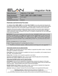
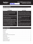
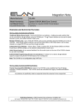
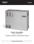
Integration Note
Manufacturer:
Aprilaire
Model Number(s):
8800 Thermostat
Minimum Core Module Version:
g! 5.4.104
Document Revision Date:
2/14/2013
OVERVIEW AND SUPPORTED FEATURES
THE 8800 THERMOSTATS SUPPORT THE FOLLOWING FEATURES:
Temperature Control: Temperature control can be managed by schedules tied to house modes or by
manual control based on time (Timed Temporary Hold, Temporary Hold and Permanent Hold).
Temperature can be shown as either Fahrenheit or Celsius on the viewer interface.
Mode Control: The climate system can be set to run in the following heating and cooling modes: Heat
only, Cool only, Auto Heat Cool, Emergency Heat or Off.
Fan Mode Control: Systems that have a fan can be set to run in Automatic, Continuous or Circulate
mode.
History View: The history view shows the inside temperature, outside temperature, unit run and fan run
times, and cooling and heating set points.
Schedule Control: Multiple schedules can be set using the Viewer software and configured using the
configurator. Up to 10 schedules can be created and are tied to the system mode.
Outside Air Temperature: The outside air temperature can be obtained from the weather information on
the web, a sensor connected to the thermostat, or monitored using an 8081 or 8082 Support Module. The
outside air temperatures can be displayed in real-time or tracked in history for each thermostat in the
Viewer.
Humidity Display: Although humidity control is not supported, the humidity value can be obtained from a
humidity sensor in the 8800 in the thermostat and humidity mode; from a humidity sensor in the 8082, or
from the web. You can display the value on the history graph; on a custom graph using a Graph View
control, or as a custom text display using the Numeric text control. Note: If a thermostat is configured as a
humidistat, then it must be removed from all interfaces.
Auto Time and Date: The g! system will automatically update the time and date on the thermostats
including daylight savings time changes.
Auto Thermostat Detection: The g! system will automatically detect all the thermostats connected to
system, along with each thermostat’s ID (number).
Celsius and Fahrenheit: Aprilaire Thermostats support displaying Temperatures in C or F both at the
stat and in the g! system in whole number values. Decimal place display and control is not supported for
these thermostats.
Remote Room Temp Sensor connected directly to 8800 Thermostat: The 8800 can be configured to
utilize a remote temperature sensor in place of its on board sensor. The sensor connects directly to its T1
& T2 terminals. When properly connected and configured this sensor will override the onboard sensor
and the thermostat then reports the remote sensor value to the system controller as its room temperature
value. Please refer to the Aprilaire documentation for setup information.
ELAN Home Systems ● 1690 Corporate Circle ● Petaluma, CA 94954 USA
tech support: 800.622.3526 • main: 760.710.0990 • sales: 877.289.3526 • email: [email protected]
©2013 ELAN Home Systems. All rights reserved. ELAN and g! are trademarks of ELAN Home Systems. All other trademarks are the property of their respective owners.
THE 8800 THERMOSTATS DO NOT SUPPORT THE FOLLOWING FEATURES:
Humidity Control: Humidity control is not supported.
Legacy 8061 and 8062 support modules: The 8800 thermostat is not compatible with the legacy
support modules. They must use the replacement 8081 or 8082 support modules.
Celsius and Fahrenheit Decimal Display: Temperature Decimal place display and control for
temperature values is not supported for these thermostats.
Any feature not specifically noted as “supported” is not supported.
2 of 11
INSTALLATION OVERVIEW
1. Install the Aprilaire RS-485 thermostat network and control cables during the rough-in phase. Consult
the Aprilaire Model 8800 Communicating Thermostat System Installation Manual for details and
control cabling requirements. This document and others pertaining to this system can be found at
www.aprilairecontractor.com.
2. Communication wiring:
a. Each Model 8819 Distribution Panel supports up to 8 thermostats. If you have more than 8
thermostats, install additional Distribution Panels and daisy-chain a Cat5 cable from one to
the next. Up to 4 Distribution Panels can be daisy chained together to provide access to 32
thermostats.
b. Run a Cat5 wire from one of the Distribution Panels back to an unused RS-485 port on the g!
system controller. (Optionally a SerialBrick may be used for communication between the
controller and the thermostat network. In this case run one Cat5 from the Distribution Panel
to the RS-485 port on the SerialBrick and one Cat5 to connect the SerialBrick’s Ethernet to
the home network.)
c.
Mount the Distribution Panel(s) and terminate the wires, as per the diagrams provided below.
Make sure all the power and communication switches are in the off position when making any
connections.
d. Each 8819 Distribution panel requires 24VAC for power. Refer to the Aprilaire document
referenced above for details on power connections.
3. Mount and connect the thermostats bases using the diagrams provided below.
4. Thermostat power wiring:
The 8800 thermostats are powered by the distribution panel. Refer to the Aprilaire document
referenced above for details.
5. Recheck the wiring on both at the thermostat and the Distribution Panel.
6. Install and power up the thermostats one at a time, while noting the thermostat locations on the inside
of the cover for the corresponding Distribution Panel. Program the thermostats as outlined in the
thermostat programming section below. Do not turn on the A and B switches at this time.
7. Test the thermostat and climate system to ensure that the thermostats correctly turn on the
appropriate heating or cooling equipment, and open or close the appropriate valves / dampers.
8. Connect the g! system to the Aprilaire thermostats electrically. See the wiring diagrams below for
more information.
9. Turn on all the A and B switches to the connected thermostats. The A and B LEDs on the distribution
panels will blink only when there is active communication. If the A and B lights are on solid then shut
off all switches and recheck the communication wiring.
10. Configure the g! system for the thermostats and confirm communication between the thermostats and
the Controller. Use the auto detect (Discover Devices) feature to find the thermostats on the network.
11. Configure the g! system for HVAC equipment on the Climate tab under Heating/Cooling Units.
12. Test the system by changing the set points, modes and schedules on the viewer and various
thermostats, confirming that the various components in the system are communicating with each
other.
13. Optionally, configure the climate scheduling using the configurator to create the schedule format and
the viewer to adjust the times and temperature settings as desired.
3 of 11
APRILA
AIRE 8800 SYSTEM
S
DIIAGRAM
NOTES:
1. Up
U to 8 thermo
ostats can be connected to
o a single 881
19 distribution
n panel.
2. Up
U to 4 distribu
ution panels can
c be daisy chained
c
togetther for a tota
al of 32 therm
mostats.
3. Optionally,
O
up to 4 support modules
m
can be connected
d to each therrmostat for re
emote sensing
g of
te
emperature an
nd/or humidity
y.
4. The thermosta
ats and distribution panel re
equire 24vac for power. R
Refer to the Ap
prilaire installation
do
ocumentation
n for options and
a details.
BILL OF MATERIALS
#
Device
Manufac
cturer
1
2
stat
Thermos
Duct/Remote Temperature Sensor
Flush Mo
ount Temperature Sensor
S
Wall Mo
ount Temperature Se
ensor
TT Supp
port Module
TrH Support Module
24 VAC Power supply
Distribution Panel
Aprila
aire
Aprila
aire
Aprila
aire
Aprila
aire
Aprila
aire
Aprila
aire
Aprila
aire
Aprila
aire
3
4
5
Part
Number
8800
8052
8051
8053
8081
8082
8027
8819
Protocol
RS-485
Analog
Analog
Analog
RS-485
RS-485
24VAC
RS-485
4 of 11
Connector
Type
w terminal
Screw
Pig Tail
T
Pig Tail
T
Screw
w terminal
Screw
w terminal
Screw
w terminal
Screw
w terminal
Screw
w terminal
Notes
Optiona
al,
Optiona
al,
Optiona
al,
Optiona
al,
Optiona
al,
Optiona
al,
Surface mount, in
ndoor/outdoor
Mounts flush in-w
wall, indoor
Surface wall mou
unt, indoor
remote temperatu
ure sensing
remote temperatu
ure and humidity se
ensing
see Aprilaire insttallation manual for options
WIRING DIAGRAM 1: RS-485 CONNECTIONS TO THE THERMOSTAT AND THE OPTIONAL SUPPORT MODULE(S)
The diagram below shows the communication connections in more detail. Refer to the Aprilaire
installation manuals for HVAC connections, power options for the thermostat and distribution panel, and
support module options and setup.
Note that the A+/A- and B+/B- colors shown are for Cat5 EIA568B cables. See the chart below the
diagram for the EIA568A colors.
Important: The Aprilaire documentation may show different wiring for connecting the distribution
panel to their 8811 protocol adapter, use the diagram below for connecting the distribution panel
to a RS485 port on a g! system controller, MultiBrick, or SerialBrick.
(OPTIONAL) REMOTE
TEMPERATURE SENSOR(S)
BLK
TO ADDITIONAL DISTRIBUTION PANELS
18‐22AWG 2C CABLE
RJ‐45
BLK
(OPTIONAL) REMOTE
TEMPERATURE SENSOR(S)
BLK
BLK
CONNECT TO RS‐485 PORT ON g! SYSTEM CONTROLLER OR BLK
24VAC
B‐
B+
A‐
A+
A+
A‐
B+
B‐
R
C
A+
A‐
B+
B‐
R
C
8019 DISTRIBUTION PANEL
A+
A‐
B+
B‐
R
C
24VAC
ORG
ORG
ORG/WH
BLU
BLU
BLK
BLU/WHT
BLK
GRN
BLK
BRN
A+
A‐
B+
B‐
R
C
BLK
24VAC
24VAC
CAT5 CABLE
ORG
BLU
BLK
RC
C
RSB
RSA
T1
T2
(OPTIONAL)
8081 TT SUPPORT MODULE
(OPTIONAL)
8082 TrH SUPPORT MODULE
OPTIONAL OUTDOOR TEMP SENSOR
OPTIONAL REMOTE TEMP SENSOR
S2
S1
T1
T2
RSB
RSA
B+
A+
B‐
A‐
C
B
O
Y
Y2
G
RC
RH
W2
W
R
GRN
18‐22AWG THERMOSTAT CABLE
RC
C
RSB
RSA
T1
T2
T3
T4
BLU
ORG
24VAC
24VAC
BRN
GRN
ORG/WH
A+
A‐
B+
B‐
R C BLU/WHT
A+
A‐
B+
B‐
R
C
ORG
A+
A‐
B+
B‐
R C
C
R
A+
A‐
B+
B‐
R
C
BLU
BLK
BRN
(OPTIONAL) REMOTE
TEMPERATURE SENSOR(S)
BLK
ORG
ORG/WH
GRN/WH
GRN
CAT5 CABLE
See Table
18‐22AWG THERMOSTAT CABLE
24VAC FROM
PLUG‐IN TRANSFORMER
8800 COMMUNICATING THERMOSTAT
TABLE: Communications Connections to Controller
Pin
EIA 568A Colors
EIA568B Colors
A+
Orange/White
Green/White
A-
Orange
Green
B+
Green/White
Orange/White
B-
Green
Orange
5 of 11
WIRING DIAGRAM 2: RJ-45 CONNECTOR PINOUTS
6 of 11
THERMOSTAT PROGRAMMING
Once the thermostats are powered up and running properly, you need to make a few changes to the
thermostat settings to integrate properly with the g! system.
STANDARD THERMOSTAT SETUP
The changes outlined below in Table 1 assume that you are starting with a factory default thermostat.
These changes will then put the thermostat into a standard g! setup.
Step
System
Setting #
Instructions
Comments
1
Set the thermostat mode to OFF by
Pressing [Mode] until the OFF
mode is blinking. Then press
[DONE] to save.
Places the thermostat into OFF mode
2
Press [MENU] to enter the main
setup menu.
Enters the main menu screen
3
Press and hold [SETUP] for 7
seconds until the INSTALLER
SETUP ENABLED message
appears.
Enables installer setup menu button
4
Press [INSTALL SETUP]
Places the thermostat into Installer Setup
Mode and displays System Setting 00
5
00
Press the [UP] or [DOWN] arrows
as required to set the thermostat
address.
Set the thermostat network address. Set the
first thermostat to 1, the second to 2, and so
on.
6
01
Press [NEXT] right arrow button to
advance to system setting #01
Screen displays Number of Nodes setting 01
7
01
Press [UP] or [DOWN] arrow
buttons to set the total number of
thermostats on the network
Set the total number of thermostats on the
network
4
02
Press [NEXT] right arrow button to
verify the baud rate is set to 9600.
Pressing [UP] or [DOWN] will
change the setting
Screen displays Baud Rate 02. 9600 will be
flashing when it is selected properly.
5
06
Press [NEXT] right arrow button to
access the AUTO CHANGEOVER
setting
Screen displays Auto Changeover 06.
6
06
Press [UP] or [DOWN] to set to
ENABLE
ENABLE will be flashing when it is selected
properly.
7
27
Press [NEXT] right arrow button to
access the DEADBAND setting
Screen displays Deadband 27.
8
27
Press [UP] or [DOWN] to set the
DEADBAND setting to 2 degrees
The default setting of 3 must be changed to 2
9
35
Press [NEXT] right arrow button to
access the PROGRAM FORMAT
setting
The screen displays Program Format 35
10
35
Press [UP] or [DOWN] to set the
PROGRAM FORMAT setting to
NON-PROG
The screen blinks NON-PROG when properly
selected.
Press [DONE]
Thermostat saves changes exits setup mode.
11
Table 1: Steps to setup a factory default Model 8800 thermostat with standard g! settings.
7 of 11
TABLE 2: OTHER THERMOSTAT SETTINGS
In addition to the standard settings listed above, there may be situations that require additional changes
to the thermostat to configure the thermostat for the HVAC equipment or to solve a particular installation
issue.
The following table lists the thermostat settings and comments on each. Items in the g! Standard column
that are bold are items that we suggest you change, as explained above. Refer also to the Aprilaire
documentation for more information.
Refer to steps 1 thru 4 above to access the installer setup mode. Pressing [NEXT] or the right arrow will
advance thru the system settings numerically and pressing [BACK] or the left arrow will access previous
system settings. The [UP] and [DOWN] arrow buttons will adjust the setting within the fields.
Once all the settings are complete press [DONE] to save and exit or press [CANCEL] to exit without
saving the changes.
Setting #
Themostat System Setting
00
Network Address
01
Number of Nodes
02
Baud Rate
03
04
05
06
07
08
09
10
11
12
13
14
15
16
17
18
19
20
21
22
23
24
25
26
27
28
29
30
32
33
34
35
36
37
38
39
40
41
42
Controller Type
Equipment Type
Control Setup
Auto Changeover
Numer of Stages
Aux Heat Stages
Fan Control in Heating
Compressor Min Off Time
Heating Min Off Time
Equipment Min On Time
Auto Changeover Time
Remote Sensor
Outdoor Sensor
Control Sensor Backup
First Stage Differential
Second Stage Differential
Third Stage Differential
Fourth Stage Differential
Integral Factor Period
Low Balance Point
High Balance Point
Extended Fan Heat
Extended Fan Cool
Progressive Recovery
Deadband
Humidistat Mode
Temperature Scale
Auto Daylight Savings
Constant Backlight
Backlight Intensity
Sensor Offset
Program Format
Event Configuration
Events Per Day
User Security Setup
Security
Security PIN
Lockout Type
Mode Lockout
Aprilaire
Default
1
64
9600
Elan g!
Standard
1 thru N
N
9600
Thermostat
Heat/Cool
Heat and Cool
Disable
Single
One
Gas/Oil Heat
5 Minutes
2 Minutes
2 Minutes
4 Minutes
No
No
User Built-in
1F
1F
1F
1F
2 Minutes
20 F
65 F
Disable
Disable
Enable
3F
Off
Fahrenheit
March
Disable
100%
0F
7-Day
Residential
Four
Disable
Disable
####
Off
Disable
Thermostat
n/a
n/a
Enable
n/a
n/a
n/a
n/a
n/a
n/a
n/a
n/a
n/a
n/a
n/a
n/a
n/a
n/a
n/a
n/a
n/a
n/a
n/a
n/a
2F
Off
n/a
n/a
n/a
n/a
n/a
Non-Prog
n/a
n/a
n/a
n/a
n/a
n/a
n/a
8 of 11
Comments
Must be set with a unique address
N must be set to the total # of thermostats on the network
Must be 9600
Current software does not support control in Humidistat
Mode, but will support humidity monitoring
Ok to change
Ok to change
Must be set to Enable
Ok to change
Ok to change
Ok to change
Ok to change
Ok to change
Ok to change
Ok to change
Ok to change
Ok to change
Ok to change
Ok to change
Ok to change
Ok to change
Ok to change
Ok to change
Ok to change
Ok to change
Ok to change
Ok to change
Ok to change
Must be set to 2 F
Must be set to Off. If 8800 is set up as a humistat, set to On.
Ok to change
Ok to change
Ok to change
Ok to change
Ok to change
Must be set to Non-Prog
Ok to change
Ok to change
Ok to change
Ok to change
Ok to change
Ok to change
Ok to change
43
44
45
46
47
48
49
50
51
52
53
Fan Lockout
Setpoint Lockout Type
Max Setpoint Change in Lockout
Temporary Change Period
Network Override
Display Remote Sensors
Air Filter Alarm Period
Water Panel Alarm Period
Humidifier Type
Dehumidifier Alarm Period
HVAC Alarm Period
Off
Off
+/- 5 F
60 Minutes
Enable
Disable
Off
Off
Flow Though
Off
Off
n/a
n/a
n/a
n/a
n/a
n/a
n/a
n/a
n/a
n/a
n/a
Ok
Ok
Ok
Ok
Ok
Ok
Ok
Ok
Ok
Ok
Ok
to change
to change
to change
to change
to change
to change
to change
to change
to change
to change
to change
Table 2: Aprilaire Model 8800 thermostat settings, showing factory defaults and g! standards. Note the
comments to the right which indicate which values should not be changed.
9 of 11
g! CONFIGURATION DETAILS
The following table provides settings used in the g! Configurator. In the table below:
o “<Select>”
Select the appropriate item from the list (or drop-down) in the Configurator.
o “<User Defined>”, etc.
Type in the desired name for the item.
o “<Auto Detect>”, etc.
The system will auto detect this variable.
Devices
Variable Name
Communication Devices
Name
Option 1- g! System Controller or MultiBrick Type
Communication Type
Location
COM Port
Communication Devices
(Option 2-SerialBrick)
HVAC Units
Setting
<User Defined>
Serial Port
Aprilaire RS485 Network
<User Defined> (Not Required)
<Select>
Name
Type
SerialBrick Name
Communication Type
Location
<Auto Detect> See Note 1
(IP to Serial) SerialBrick
<Select from list>
Aprilaire RS485 Network
<User Defined> (Not Required)
Name
Model
Controls Heat
Controls Cooling
Controls Fan
<User Defined>
Generic HVAC Unit
<Select from list>
<Select from list>
<Select from list>
Schedules
Global Options
Select RS485 port on g! System Controller. MultiBrick must be COM 3 for RS
Click the Discover Devices button on the Communication Device
<Discover Devices>
Thermostats
Comments
Name
Location
Com Device
Thermostat #
Heating Unit
Cooling Unit
<User Defined> (Default: Thermostat1, etc.)
<User Defined> (Not Required)
<Auto Detect>
<Auto Detect>
<Select from list>
<Select from list>
HVAC Schedule
Programs
Monday - Sunday
Periods per Day
<Select from list>
<Select from list>
<Select days>
<Select from list>
Select desired number of schedules
Select desired weekly programs
Select days that go together
1, 2 or 4 periods per day
Units
Temporary Hold Mode
Temporary Hold Default Time
Outside Temperature Sensor
Outside Humidity Sensor
<Select from list>
<Select from list>
<Select from list>
<Select from list>
<Select from list>
Fahrenheit or Celsius, no decimal places. (see note 2)
Timed Hold or Hold until next schedule period
Select default Temporary Hold time
Choose optional sensor if installed or choose Internet
Choose optional sensor if installed or choose Internet
Notes:
1. The Communication Devices Name is set to New Device by default. After you select the SerialBrick, the name will change to that specified by the SerialBrick.
2. Select either Fahrenheit or Celsius no decimal places. All other options are not supported.
10 of 11
COMMON MISTAKES
1. Powering the thermostats prior to terminating the wires. If the bare wires touch damage may be done
to the power supply, distribution panels, or thermostats.
2. Programming two thermostats with the same address. Each thermostat must have a unique network
address.
3. Programming the thermostats with the incorrect number of thermostats in the system. This
information is required to allow proper communication on the RS-485 network.
4. Wiring the Aprilaire thermostats and Distribution Panel incorrectly. There are a lot of wires in this
system. Wiring a thermostat incorrectly will cause other thermostats to exhibit strange and
inconsistent behavior. Strip 0.25 inches of insulation off the wire and insert it into the connector so
that the end of the insulation is flush with the side of the connector. See the diagrams above for
details.
The switches on the Distribution Panel can be used to help isolate the bad thermostat and/or wiring
by turning off thermostats communication one at a time until the proper communication and control
can be verified.
5. Failing to plug the Cat5 cables into the correct serial port: make sure that the RJ-45 connector is
plugged into the proper RS-485 port.
6. Mis-wiring the RJ-45 connector in the cable assembly between the system controller and the
distribution panel. Incorrect wiring order, short or open connections can cause erratic network
behavior. See the wiring diagram above for details
7. Bending the pins on the thermostat. Removing the thermostat from its base has a tendency to bend
the pins. This can result in a poor connection when the thermostat is replaced in its base. Gently
bend the pins so they are straight and square to correct the problem.
8. Mounting the thermostat base on an uneven surface. Be sure the surface that the base is mounted to
is flat. An uneven surface can cause connection issues when the thermostats are seated in the base.
9. Wiring the Distribution panel according to Aprilaire documentation. The Aprilaire documentation
shows a different wiring scheme for connecting the distribution panel to their 8811 protocol adapter.
Follow the diagrams in this note for connecting Aprilaire to a g! RS-485 port.
11 of 11