1
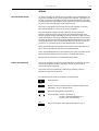
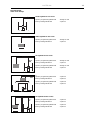
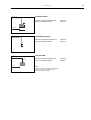
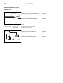
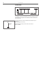
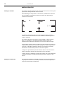
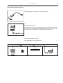
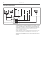
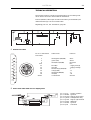
BEOLINK Master Link Handbook MASTER LINK MASTER LINK PREFACE This handbook deals with Bang & Olufsen’s BeoLink (Master Link), paying special attention to the installation requirements applying to it. Consequently, this handbook is especially targeted on dealers and installers. Any product, for example a stereo system, a PC, a natural gas system, etc., that has to be incorporated into a network needs to have certain requirements satisfied by the surroundings in connection with its installation. These requirements must ensure the optimal operation of the system after installation. The same applies to Bang & Olufsen’s BeoLink. Although the requirements are not many, it is essential that they be known since compliance with the basic requirements often determines whether or not the system is able to operate once the installation has been completed. The handbook gives a brief and precise introduction to the basic rules that must be observed in connection with a BeoLink installation, and it describes how compatibility is achieved between Master Link products and Master Control Link products. The handbook has been designed partly as a reference book but the entire handbook should be read in order to obtain the total overview. Only then will it serve its purpose as a reference book. MASTER LINK CONTENTS 1 READING INSTRUCTIONS How should I read this handbook 2 GENERAL DESCRIPTION What is a BeoLink system/Master Link system, and what can it do for me? 4 PRODUCT DESCRIPTION Description of BeoLab 3500, BeoLab 2000 and BeoLink boxes 11 SETUPS Description of recommended Master Link setups, compatibility setups, special setups and option programming 22 DIMENSIONING Description of how much cable may be used 23 INSTALLATION TYPES Description of various installation types 26 INSTALLATION TIPS Practical advice for use in connection with installation 29 TECHNICAL DESCRIPTION Description of various cables which are typically used 32 TROUBLESHOOTING GUIDE What could be wrong when the system will not operate? 35 GLOSSARY Description of specific words and abbreviations 39 ACCESSORIES LIST 45 FOR NOTES MASTER LINK 1 READING INSTRUCTION This handbook employs various symbols to illustrate audio products, video products and speakers. Unless otherwise specified in the text, these symbols merely have to be understood as covering one of these product areas and not as the specific product which the illustration may depict. Since the handbook is focusing particularly on the basic rules in connection with the installation of the systems, variables which are specific to particular products have been omitted to the greatest possible extent. This means that the handbook will always be relevant in connection with installation of the Master Link; both with regard to products launched prior to the publication of the handbook and products that will be launched later. The basic rules applying to the Master Link will always be the same. If information specific to a particular product is required, please see Bang & Olufsen’s Product Configuration Guide. 2 MASTER LINK GENERAL DESCRIPTION What is BeoLink? BeoLink is a Bang & Olufsen expression that covers: 1. The ability to create and operate audio-video systems, and 2. The ability to distribute sound and picture from a Bang & Olufsen main room system to other rooms in the home, and to operate the main room system from the rooms connected by means of BeoLink. BeoLink is not a product - it is a number of features that are the result of the intelligent interaction between products, a synergy effect. BeoLink may be obtained in different ways, depending upon the products that are used: basically either the Audio Aux Link/Master Control Link (MCL) system or the Master Link system. The latter is the most recent system, and the long-term objective is that it shall replace the other system. Introducing Master Link Master Link perceived as an interconnection method offers some convenient benefits not available with the MCL system. An example is that whereas the interconnection in the main room previously had to be carried out with one type of cable (Audio Aux Link) and the interconnection between the main room and the link rooms with another type of cable (Master Control Link), the new Master Link connection offers a bustype connection that caters for all interconnections between the main room audio and video systems as well as connections to the link rooms. Another benefit is the completely individual volume control and tone adjustments in each link room, due to the distribution of audio signals at line level and the application of power amplifiers in each link room. Contrary to the previous signal distribution system, Master Link signals are distributed as balanced signals, permitting distribution of CD-quality sound, even when the cable distances are fairly long. Finally, the distribution hardware has been improved, e.g. by the introduction of a reduced signal cable diameter and new cable termination methods. The benefit of this improvement is that installation has become simpler and more elegant. The simplification is most evident in smaller installations, e.g. the installation of an intelligent kitchen loudspeaker being intuitively and quickly accomplished, whereas larger installations still require some planning and installation skills - as implied by the presence of this booklet. MASTER LINK 3 BeoLink distribution covers the ability to distribute both audio and video signals. In the Master Link system audio and control signals are distributed by means of one single cable, whereas the distribution of video signals requires a coaxial cable network. Only BeoLink compatible products can be fully integrated in a BeoLink system, but previous system products may be integrated to a limited extent, as described in the chapter on Compatibility setups, page 17. 4 MASTER LINK PRODUCT DESCRIPTION Below you will find a description of the individual elements included with the Master Link products as well as their scope of application. Content BeoLab 3500 The BeoLab 3500 is an integrated link room speaker consisting of an active speaker with Master Link (ML) connection, an IR receiver and a display. BeoLab 3500 also has Master Control Link (MCL) connection. Furthermore, the BeoLab 3500 has a built-in clock. The BeoLab 3500 is supplied with a mains lead and a bracket for wall mounting. Application The BeoLab 3500 is used in link rooms where you wish to have an integrated active speaker. From the BeoLab 3500 it is possible to listen to all sources from the main room, both audio and video sources. BeoLab 3500 has built-in sound control, meaning that tone and volume can be adjusted independently of the main room. With the tone control it is possible to adjust balance, bass, treble and loudness individually. BeoLab 3500 offers the following local operation features: - Timer on/off - PLAY / ST.BY Part no. 1160111 (EU) 1160211 (GB) 1160311 (USA/CDN) 1160411 (JAP) 1160511 (AUS) Miscellaneous Besides the parts included with the BeoLab 3500, the installation may require a Master Link cable as well as plugs, sockets and junction boxes (see the section on installation types, page 23). MASTER LINK Content 5 BeoLab 2000 BeoLab 2000 is an integrated link room speaker consisting of an active speaker with Master Link (ML) connection, an IR receiver and close-up operation. The BeoLab 2000 is supplied with a mains lead and a bracket for wall mounting. BANG & OLUFSEN 3m Application The BeoLab 2000 is used in link rooms where you wish to have an integrated active speaker. From the BeoLab 2000 it is possible to listen to all sources from the main room, both audio and video sources. BeoLab 2000 has built-in volume control, meaning that volume can be adjusted independently of the main room. BeoLab 2000 offers the following close-up operation features: - Timer on/off PLAY / ST.BY Volume up and down Close-up selection of Radio, CD or Tape Step-button for switching programs or tracks Part no. 1164129 (EU) 1164229 (GB) 1164329 (USA/CDN) 1164429 (JAP) 1164529 (AUS) Miscellaneous Besides the parts included with the BeoLab 2000, the installation requires a Master Link cable as well as plugs, sockets and junction boxes (see the section on installation types, page 23). 6 Content MASTER LINK BeoLink Active BeoLink Active consists of a control box, an IR receiver, a receiver cable and a mains lead. Application BeoLink Active speakers are used in link rooms where active speakers are required. All Bang & Olufsen active speakers may be connected. BeoLink Active has built-in sound control, meaning that tone and volume can be adjusted independently of the main room. With the tone control it is possible to adjust balance, bass, treble and loudness individually. With a BeoLink Active it is possible to listen to the sound from all main room products - both the video and audio sources. BeoLink Active offers the following local operation features: - Timer on/off - PLAY / ST.BY - Volume up and down Part no. 1161666 1161866, (USA/CDN) Miscellaneous Besides the parts included with the BeoLink Active, the installation requires a Master Link cable as well as plugs, sockets and junction boxes (see the section on installation types, page 23). MASTER LINK Content 7 BeoLink Passive BeoLink Passive consists of a control box, an IR receiver, a receiver cable and a mains lead. Application BeoLink Passive speakers are used in link rooms where passive speakers are required. All Bang & Olufsen passive speakers may be connected. BeoLink Passive has built-in sound control, meaning that tone and volume can be adjusted independently of the main room. With the tone control it is possible to adjust balance, bass, treble and loudness individually. With a BeoLink Passive it is possible to listen to the sound from all main room products - both the video and audio sources. BeoLink Passive offers the following local operation features: - Timer on/off - PLAY / ST.BY - Volume up and down Part no. 1165566 (AUS) 1165666 (EU) 1165766 (GB) 1165866 (USA/CDN) Miscellaneous Besides the parts included with the BeoLink Passive, the installation requires a Master Link cable as well as plugs, sockets and junction boxes (see the section on installation types, page 23). 8 Content MASTER LINK BeoLink Video BeoLink Video consists of a control box, a mains lead and a datalink cable. Apart from this you need an coaxial cable from the HF outlet of the video system in the main room. This cable is connected to the aerial input of the link room TV. Application BeoLink Video is used in link rooms where both sound and picture are required via a Bang & Olufsen TV set. With BeoLink Video it is possible to use all the sources in the main room. In particular it is possible to operate SAT and V.TAPE but it is further possible to watch a decoded programme from the TV set in the main room. In addition, it is possible to operate all audio sources, thereby using the speakers in Bang & Olufsen’s TV sets for obtaining audio sound. If you want even greater sound in the room you can connect Bang & Olufsen’s active speakers to the TV set. BeoLink Video is connected to the TV set by means of the 7-pin datalink cable and to the main room with a Master Link cable. Apart from this an aerial installation is needed (see page 24). Part no. 1161566 Miscellaneous Besides the parts included with the BeoLink Video, the installation requires a Master Link cable as well as plugs, sockets and junction boxes (see the section on installation types, page 23). MASTER LINK Content BeoLink Converter BeoLink Converter consists of a control box and a mains lead. 1.5 m Application BeoLink Converter is used when audio and video products with Master Link and Audio Aux Link (datalink) have to be interconnected. BeoLink Converter can be used in conjunction with both a video and an audio master. BeoLink Converter features autoconfiguration, meaning that it is able to detect automatically whether it is installed in a Master Link audio or in a Master Link video system. Configuration takes place when it is connected to the mains. BeoLink Converter can also be used as ML-driver*, which means that it is possible to connect e.g. a BeoCenter 2300 via the BeoLink Converter to the Master Link and thereby distribute sound to all link room products (see page 17). BeoLink Converter is used in compatibility setups (see the section on recommended compatibility setups, page 17). Part no. 1161166 1161266 (USA/CDN) 1161466 (old version) Miscellaneous Besides the parts included with the BeoLink Converter, the installation requires a Master Link cable as well as plugs, sockets and junction boxes (see the section on installation types, page 23). *NOTE! BeoLink Converter type no. 1161466 can not be used as ML-driver. 9 10 MASTER LINK Content ML/MCL Converter ML/MCL Converter consists of a control box and an amplifier. 1.5 m Application ML/MCL Converter is used where a conversion from Master Link (ML) to Master Control Link (MCL) is wanted. Such a conversion is required if you want to maintain the existing Master Control Link system although the audio system in the main room is replaced with a Master Link driver, for example a BeoSound Ouverture. ML/MCL Converter can also be used in conjunction with a Beosystem AV 9000 with an AV 9000 Master Panel. See setups with ML/MCL Converter, page 19. Part no. 1165066 (AUS) 1165166 (EU) 1165266 (GB) 1165366 (USA/CDN) Miscellaneous Besides the parts included with the ML/MCL Converter, the installation requires a Master Link cable as well as plugs, sockets and junction boxes (see the section on installation types, page 23). MASTER LINK 11 SETUPS Recommended setups An object consisting of several parts can usually only be assembled in one way if the intended result is to be achieved. For example, a gearbox for a car will not perform optimally according to the specifications if you omit installing some of the gearwheels. If you manage to install one gearwheel too many, that will most likely cause trouble as well. The point of the above is that things must be put together in the way they were designed to, if they are to perform optimally. The same applies to Bang & Olufsen’s BeoLink. In theory, Bang & Olufsen’s products may be connected in thousands of different ways. Since it would be totally impossible to have an overview of just a fraction of this multitude of connection possibilities, Bang & Olufsen has selected the most attractive combinations. These selected combinations are called recommended setups. The recommended setups are the ones which are focused on in connection with product development and service. When a BeoLink system is configured it is therefore very important that this is done in accordance with the recommended setups. If the recommended setups are not followed, the result may easily be the same as with the gearbox with too many or too few gearwheels. Bang & Olufsen services the recommended setups ONLY. Option programming One of the conditions for the recommended setups to perform optimally is that the products included in the setup “know” in what kind of environment they are placed. The actual option programming is executed by pressing a certain sequence of keys on the terminal. For the Beo4 terminal the key sequence is the following: Press and hold then Press to access the setup function. The Beo4 display reads [OPTION?] - let go of both buttons Press to access Option-programming Press to display [V.OPT] BeoVision, or [A.OPT] Beomaster/BeoSound, or [L.OPT] link room products then Key in the number of the appropriate Option, e.g. 1 12 MASTER LINK For the Beolink 1000 terminal the key sequence is the following: Beovision: “digit” Beomaster/BeoSound: “digit” Link room products: “digit” The digit sequence to be used depends on the setup. Option 0 Option 1 Option 2 Option 4 = = = = No IR reception Two IR-eyes in the same main room One IR-eye in the main room Link room product connected to one or two main room products in the same room Option 5 = Two IR-eyes in the same link room Option 6 = One IR-eye in the link room It applies to most setups that they are delivered with the correct option setting from the factory, and they are thus “ready for use”. However, since in some situations you may have to work with products that have been installed before, e.g. in connection with a house that has been rebuilt, the correct option is indicated at ALL illustrations, even those which are “ready for use” from the factory. NOTE! If the option programming is not executed correctly, a malfunction will occur. 13 MASTER LINK Recommended main room setups Audio system in one room Option programming BeoSound Factory setting BeoSound : Ready for use : Option 1 Video system in one room Option programming BeoVision Factory setting BeoVision : Ready for use : Option 1 AV system in one room 1. Option programming BeoVision Factory setting BeoVision : Ready for use : Option 1 Option programming BeoSound Factory setting BeoSound : Ready for use : Option 1 2. Option programming BeoVision Factory setting BeoVision : Option 2 : Option 1 Option programming BeoSound Factory setting BeoSound : Option 0 : Option 1 AV system in two rooms Option programming BeoVision Factory setting BeoVision : Option 2 : Option 1 Option programming BeoSound Factory setting BeoSound : Option 2 : Option 1 14 MASTER LINK Recommended setups for one product in the link room BeoLab 3500 Option programming Factory setting : Ready for use : Option 6 BeoLab 2000 Option programming Factory setting : Ready for use : Option 6 BeoVision MX 4002 Master Link Option programming Factory setting : Ready for use : Option 6 Coaxial BeoLink Active Option programming Factory setting Master Link : Ready for use : Option 6 BeoLink Passive Option programming Factory setting : Ready for use : Option 6 15 MASTER LINK BeoVision Avant Master Link Option programming BeoVision Factory setting BeoVision : Option 6 : Option 1 Coaxial BeoSound Ouverture Master Link Option programming BeoSound Factory setting BeoSound : Option 6 : Option 1 BeoLink Video Master Link BeoLink Video Datalink Option programming BeoVision Factory setting BeoVision Coaxial NOTE! Option and setups for a BeoVision connected to BeoLink Video, see Bang & Olufsen's Product Configuration Guide. : Option 6 : Option 1 16 MASTER LINK Recommended setups for one Audio and one Video product in the link room Master Link Coaxial Master Link Audio* Video** *NOTE! Valid for all Audio link room products. **NOTE! Valid for Video link room products incl. BeoLink Video. Master Link Master Link Coaxial 1. Option programming BeoLab/BeoLink Factory setting BeoLab/BeoLink : Option 5 : option 6 Option programming BeoVision MX 4002 : Option 5 Factory setting BeoVision MX 4002 : Option 6 NOTE! Option and setups for a BeoVision connected to BeoLink Video, see Bang & Olufsen's Product Configuration Guide. 2. Option programming BeoSound Factory setting BeoSound : Option 5 : Option 1 Option programming BeoVision Avant Factory setting BeoVision Avant : Option 5 : Option 1 17 MASTER LINK Recommended compatibility setups Master Link Master Link BeoLink Converter Compatibility between products with Master Link connection and Audio Aux Link (datalink) connection or Master Control Link connection. One room setup 1. Option programming BeoVision Factory setting BeoVision : Option 2 : Option 1 Option programming Beomaster Factory setting Beomaster : Option 0 : Option 1 2. Option programming BeoVision Factory setting BeoVision : Ready for use : Option 1 Option programming BeoSound Factory setting BeoSound : Ready for use : Option 1 3. Option programming BeoVision Factory setting BeoVision : Ready for use : Option 1 Option programming Beomaster Factory setting Beomaster : Ready for use : Option 1 4. Option programming Factory setting : Ready for use : Option 1 5. Option programming BeoVision Factory setting BeoVision : Ready for use : Option 1 Option programming BeoSound Factory setting BeoSound : Ready for use : Option 1 Datalink Master Link BeoLink Converter Datalink Master Link BeoLink Converter Datalink Datalink AUXT-branch NOTE! Information as to which Beomasters and BeoVisions can be connected to BeoLink Converter, see Bang & Olufsen's Product Configuration Guide. 18 MASTER LINK Two room setup 1. Option programming BeoVision Factory setting BeoVision : Option 2 : Option 1 Option programming BeoSound Factory setting BeoSound : Option 2 : Option 1 2. Option programming BeoVision Factory setting BeoVision : Option 2 : Option 1 Option programming Beomaster Factory setting Beomaster : Option 2 : Option 1 NOTE! Information as to which Beomasters and BeoVisions can be connected to BeoLink Converter, see Bang & Olufsen's Product Configuration Guide. 19 MASTER LINK Setups with ML / MCL Converter This product is used where the customer wishes to maintain his current MCL system and to replace the audio system in the main room with a Master Link driver. The ML/MCL Converter can be connected to all recommended MCL link room setups, see the Master Control Link Handbook. MCL Master Link BeoLink Video Datalink 1. Option programming BeoSound Factory setting BeoSound : Ready for use : Option 1 2. Option programming BeoVision Factory setting BeoVision : Ready for use : Option 1 Option programming BeoSound Factory setting BeoSound : Ready for use : Option 1 3. Option programming BeoVision Factory setting BeoVision : Ready for use : Option 1 Option programming BeoSound Factory setting BeoSound : Ready for use : Option 1 Master Link 20 MASTER LINK Special setups Further to the recommended setups, there are two additional combinations. The reason why they are not mentioned under recommended setups is that they do not fully live up to Bang & Olufsen’s own standards as regards operating simplicity. They have been included anyway, because in some situations they might be appropriate, and they will always permit operation of the basic functions such as source selection (radio, CD, a.tape, etc.), source control (fast forward and rewind, step, selection of a certain track, etc.) and volume control. Link room products or link room kits in the main room. If an additional listening area is required in the main room, e.g. if it is an L-shaped room, it is possible to operate it without activating the listening area by the AV system (the speakers connected to the centrally placed audio system), it is possible to install link room products and link room kits in the main room. Option programming link room product : Option 4 Audio/video system : See main room setups Note: - The AV system is operated in the ordinary way. - The extra listening area will only understand information from the terminal if the LINK key is actuated prior to a source selection (CD, radio, a.tape, etc. ) MASTER LINK 21 Moreover, option 4 can be used if the link room and the main room are located in such a way that both rooms will be operated simultaneously. By setting the link room to option 4, the room can be operated independently of the main room, because the link room will only accept information from the terminal if the LINK key has been actuated. NOTE! The BeoLink Video cannot be set to option 4! All link room products and link room kits with Master Link connection, with the exception of BeoLink Video, can be incorporated into this special setup. NOTE! The Beolab 3500 S/W version must be 1.1 or higher 22 MASTER LINK DIMENSIONING Max. 400m ML Cable It is possible to interconnect 16 Master Link products, including the main room products, in one system, and a maximum of 400 m of Master Link cable may be used. The cable between the receiver and BeoLink Active/Passive may not exceed 5 m. 5 m is included from the factory. A special 15 m low capacity receiver cable can be ordered, part no. 6270668. MASTER LINK 23 INSTALLATION TYPES The following section gives a brief introduction to two typical installation types, namely the visible and the invisible installation. The examples include various applications of Bang & Olufsen’s installation accessories, which are shown at the end of the handbook. The illustrations give only a few installation examples. There are many alternatives, of course. Visible installation A visible installation is used where it is not possible to hide cable and installation materials in the attic and/or in conduits in the wall. In this example the following has been used: 1. 2. 3. 4. 5. 4 x Master Link cable with one plug Master Link cable without plugs 2 x Master Link junction box 1 x BeoLink Video 1 x datalink cable (included with BeoLink Video) Invisible installation This type of installation makes it possible to hide the cables and installation materials in the wall and/or in the attic. In this example the following has been used: 1. 2. 3. 4. 5. 6. 4 x Master Link cable with two plugs Master Link cable without plugs 4 x Master Link wall socket 1 x Master Link junction box 1 x BeoLink Video 1 x datalink cable (included with BeoLink Video) 24 MASTER LINK Another type of invisible installation is shown below. This installation can be made for example in apartments with no access to the attic or basement. In this example the following has been used: 1. 2. 3. 4. 5. 4 x Master Link cable with two plugs Master Link cable without plugs 4 x Master Link wall socket 1 x datalink cable (included with BeoLink Video) 1 x BeoLink Video Aerial installation Aerial installation with built-in splitter. Aerial installation with external splitter. MASTER LINK Build-in kit for IR-eye 25 The build-in kit for IR-eye is used for invisible installations. There are two different build-in kits. One for solid walls (part no. 3375187), which contains a fixture box, a spacer piece, a plastic cover (to close the box under construction) and an ornamental ring. The other kit is for light partition walls (part no. 3375188) and contains two brackets and an ornamental ring. 26 MASTER LINK INSTALLATION TIPS Placing of receiver The receiver must be placed so that nothing prevents it from receiving the signals from a Bang & Olufsen remote control. When deciding on the position of the receiver, remember that it should not be possible to activate more than one receiver at a time using a remote control terminal. The diagram shows that receiver 3 is placed appropriately, whereas receiver 1 can be activated from room 2. Receiver 1 should be placed as receiver 2 instead. The receiver should not be placed in direct sunlight or direct artificial light ( e.g. spotlight) or near objects producing electric noise (e.g. dimmers) as this reduces the sensitivity of the receiver (shorter range). If the receiver is placed outdoors, please note that it does not function at temperatures above 55ºC or below 0ºC. If higher or lower temperatures may occur, it should be possible to switch it off by means of a switch. Otherwise it can block the operation of the whole system. It might be a good idea to place the receiver next to a door so that it is easy for the person entering or leaving the room to operate it. It might also be an advantage to place the receiver close to the telephone so that the speakers can easily be muted by the person talking on the phone. Placing of control box The control box need not be placed in the same room as the receiver, but may be placed in the attic, for example. Please, note that temperatures may not be above 55ºC or below 0ºC. MASTER LINK 27 Use of Master Link junction box: 1. Length-adjustment of cable, e.g. from 10 m to 8.5 m. 2. Colour-change of cable. For aesthetical reasons all ML cables with plugs are available in the colour black only. When making visible installations it may be necessary to use a grey cable which can easily be connected via the junction box. 3. Connections between products. Max. 4 ML cables in one junction box. 28 MASTER LINK Central placing of BeoLink boxes BeoLink Passive BeoLink Active Cupboard or basement or attic BeoLink Video As appears from the illustration, BeoLink boxes can be placed in a central location. (However, maximum cable lengths may not be exceeded, and the same applies to maximum and minimum ambient temperatures. See the sections 'Dimensioning', page 22, and 'Placing of control box', page 26, for further information). Possible advantages of a central placing could be that the BeoLink units are easier to hide, BeoLink boxes can use a joint current output, etc. The BeoLink boxes are designed to function within a temperature range of 10 – 40°C. 29 MASTER LINK TECHNICAL DESCRIPTION The following section contains a brief description of the cabling most often used in connection with a BeoLink installation. Pictures (satellite, video tape recorder and ordinary TV broadcasts) are distributed through a 75 ohm coaxial cable. Regarding part nos., see 'Accessories', page 39. Master Link cable Pin no. in the Master Link socket 1 2 3 4-10 11 12 13 14 15 16 Screen Cable colour Function white/green (WH/GN) green (GN) white/blue (WH/BL) data data + ML-sense N.C. - supply voltage + supply voltage -L +L -R +R Ground blue (BL) pink (PI) white/orange (WH/OR) orange (OR) white/red (WH/RD) red (RD) 3 x solid wire Power Link cable with wire for display data. pin 1 pin 2 pin 3 pin 4 pin 5 pin 6 pin 7 pin 8 = = = = = = = = grey = shield = brown = yellow = green = white = shield = pink = power up/down ground signal, left channel loudspeaker relay signal, right channel Datalink ground overload 30 MASTER LINK Power Link cable without wire for display data pin 2 pin 3 pin 4 pin 5 17 15 13 20 18 16 14 12 11 10 9 8 7 6 5 4 3 2 1 1 2 3 6 4 15 13 11 9 7 5 16 18 20 17 19 8 21 10 12 14 2 1 6 3 4 15 13 11 9 7 5 16 17 19 18 20 8 21 10 12 14 pin 1 = pin 2 = pin 3 = pin 4 = pin 5 = pin 6 = pin 7 = pin 8 = pin 9 = pin 10 = pin 11 = pin 12 = pin 13 = pin 14 = pin 15 = pin 16 = pin 17 = pin 18 = pin 19 = pin 20 = pin 21 = ground signal, left channel loudspeaker on signal, right channel audio out, right channel audio in, right channel audio out, left channel audio ground blue ground audio in, left channel blue signal (C out) 12 V sense and Datalink green ground data 2 green signal data 1 red ground fast blanking, ground red signal (C in) fast blanking video out, ground video in, ground video out, signal (Y out) video in, signal (Y in) shield, ground Datalink cable pin 1 pin 2 pin 3 pin 4 pin 5 pin 6 pin 7 shield = brown = yellow = green = 21-pin A/V cable with RGB connection: 21 19 = = = = Coaxial cable Regarding coaxial cable for aerial installation, see the section on aerial installation, page 24. = yellow = shield = blue = red = green = black = white = output, left channel = signal ground = input, left channel = output, right channel = input, right channel = data ground = datalink 31 MASTER LINK Receiver cable 1 2 3 4 5 1 2 3 4 5 = = = = = Yellow Grey Green White Brown NOTE! Disconnect your entire Bang & Olufsen system from the mains while you make the connections! 32 MASTER LINK TROUBLESHOOTING GUIDE Master Link products, e.g. BeoLab 3500 When carrying out troubleshooting on a Master Link installation, the first thing to do is to apply the method of exclusion. First disconnect the main room and the link room, one at a time, to ascertain whether the fault is in the main room or in the link room. Then disconnect the individual products, one at a time, until the faulty product or the faulty connection has been found. Simple measurements on the Master Link can be made by means of a voltmeter or an oscilloscope. All listed specifications are measured to ground. The following specifications apply to Master Link: Pin no. in the Master Link socket Cable colour Function Specification 1 2 3 4 - 10 11 white/green green white/blue -0.25 V ± 0.1 V +0.25 V ± 0.1 V blue data data+ ML-sense no connection - supply voltage 12 pink +supply voltage 13 white/orange audio -L 14 orange audio +L 15 white/red audio -R 16 red audio +R Screen Ground (N.C.) -7 V to -15V in standby -3V to -15V +7 V to +15 V in standby +3V to +15V 1 V Bal Rin 2.2 Mohm, Rout 75 ohm 1 V Bal Rin 2.2 Mohm, Rout 75 ohm 1 V Bal Rin 2.2 Mohm, Rout 75 ohm 1 V Bal Rin 2.2 Mohm, Rout 75 ohm 3 x solid wire The data speed is 19,200 bits/sec. By way of comparison, the data speed for the Master Control Link is 160 bits/sec. MASTER LINK Trouble No sound and no operation 33 Possible cause The product is connected to the mains and the stand-by diode is on. If the above is OK, do as follows: - Meter data+ (pin 2) relative to ground Meter data- (pin 1) relative to ground Where no transmission, +/- 200 to 300 mV should be metered. When data is being transmitted, 0V should be metered. Measurement with oscilloscope. Meter the following: No transmission ———————————— + 0.25 ———————————— 0 ———————————— -0.25 Transmission If data- and data+ are not as shown at “No transmission” and are unable to transmit, the fault may be in the main room’s BeoVision or BeoSound, since it is one of these two units that supplies this voltage. Please note that in setups with a BeoLink Converter it is always the Master Link driver that supplies the voltage. If there are two Master Link drivers, one of them will, when connected, configure itself as being the one that supplies the data voltage. The fault is found by applying the method of exclusion. If the fault is not in one of the Master Link drivers, there is another product that pulls data low or high respectively. Alternatively there could be a cable fault or a connection fault. Data errors can also be displayed in service mode; see the section on service mode. If data is OK, proceed with the measurement of the supply voltage which should be as stated under the specifications. If the voltage is not OK, apply the method of exclusion until the faulty product or the faulty connection has been found. No sound but operation OK The data and supply voltages are in this case OK. Meter the signal levels at pins 13 to 16 in relation to the stated specifications. If the signal levels are OK, the fault is in the link room product, perhaps in the converter box, or it may be a faulty cable or connection. Play only at half volume One of the balanced audio signals has dropped out. 34 Service mode MASTER LINK Products with a display feature a service mode in which Master Link faults can be displayed. Please note that the error reading indicates that the fault is a system fault, which does not mean that the fault is in the particular product that is displaying it. Beolab 3500 and BeoVision Avant are examples of products providing the service mode feature. Check the service manual for the individual products to see how these procedures are accessed. This example of service mode is from Beolab 3500. ERROR 1: - Address configuration is impossible. Error during address configuration. No address has been allocated because too many units are connected to the Master Link. - Remove all products from Master Link, and connect them again one at a time until the error code occurs. Disconnect that product from Master Link. ERROR 2: - Master Link data pulled low It is not possible to transmit on Master Link, because it has been pulled low. The error may occur if there is no Master Link driver circuit, or as a result of a physical short-circuit on Master Link or in the data transceiver circuits. - Disconnect one product from Master Link at a time, and see if it starts up. - Reset the faulty product, and check the connection (cable/plug) and signal path (the data transceiver circuit). See repair tips for the data transceiver circuit. ERROR 3: - Master Link data pulled high. It is not possible to transmit on Master Link, because it has been pulled high. This error is caused either by the pull-up resistance in the system having become too small or by an error in the data transceiver circuit. - Disconnect one product from Master Link at a time, and see if it starts up. - Reset the faulty product, check whether the Master Link cable is too long, and check the signal path (the data transceiver circuit). See repair tips for the Master Link data transceiver circuit. ERROR 4: - Data collision on Master Link The data traffic on Master Link has been excessive, or a product has jammed and will not receive data telegrams. - Press the operating sequence again. - Disconnect one product from Master Link at a time to determine which product has jammed. Reset the faulty product, and check the Master Link connection (cable/plug) and signal path (amplifiers in the data transceiver circuit). See the service manual for the individual products for further information. MASTER LINK 35 GLOSSARY Audio Aux Link Perhaps better known as AV connection . Connection between the audio and video systems. The connection is established through a 7-pin datalink cable. 21-pin AV cable / SCART Standard connection between a TV set and a video tape recorder. The cable is specified for transferring RGB signals. AV system Audio/video system. Integration of audio and video, permitting sound to be transferred from one system to the other. BeoLink The brand name and a general term describing Bang & Olufsen’s way of distributing sound and picture. BeoLink may be obtained in different ways depending on the products used: either the Audio Aux Link/Master Control Link (MCL) system or the Master Link system. Beomaster Designation of audio masters, e.g. Beomaster 7000 and Beocenter 9500. In future this designation will be replaced by BeoSound. BeoSound Common designation of audio products, e.g. BeoSound Ouverture. BeoVision Common designation of TV sets, e.g. Beovision MX 6000 and BeoVision Avant. Compatibility The ability to interconnect products from different seasons. Control box A box that controls data and signals, for example in BeoLink Active. Datalink cable 7-pin datalink cable used for Audio Aux Link connection between audio and video systems. Link room Designation of the other room/rooms in the home in which sound and/or picture are installed. Link room kits Kits specially designed for link rooms, e.g. BeoLink Active and BeoLink Video. Link room products Products specially designed for link rooms, e.g. Beolab 3500. Main room Designation of the room in which the audio and/or video systems are placed. There are two kinds of main rooms ONE-room = audio and video systems placed in the same room TWO-room = audio and video systems placed in separate rooms. Main room products Products which serve as driver in a BeoLink system, e.g. BeoVision and BeoSound. 36 MASTER LINK Master Control Link (MCL) Master Control Link is the name of the former connection between main room and link room. Master Link (ML) Bang & Olufsen’s new systems interface. Master Link is the connection between the products in the main room and those in the link room but it is also the connection between the audio system and the video system. Master Link driver BeoSound and BeoVision with Master Link socket. One of these products is always required in a Master Link setup. Master Link product All products with a Master Link socket. One-way remote control A remote control terminal that operates the products by transmitting a command to them without requiring an answer (e.g. BL 1000 and Beo4). BL 5000 and BL 7000 are two-way remote control terminals which require an answer from the product being operated. Option programming Option programming is executed via a Bang & Olufsen terminal and with the products concerned in stand-by. Upon completed option programming, the products “know” what kind of environment they are placed in, and they can then be operated and function optimally. Power Link (PL) The Power Link connection contains all necessary signals and data required for driving active speakers. Two different types of cable are available: one with wire for display data and one without wire for display data. Note that the latter cannot be used for active speakers with display. Product Configuration Guide (PCG) A PC-based tool in which it is possible to compose the setup you want and which provides answers to any questions concerning compatibility, setups, options, terminals, special conditions, and much more. Receiver IR receiver built into video, audio and link products. The products can thus be operated by means of a one-way remote control terminal, e.g. Beolink 1000 and Beo4. MASTER LINK Notes : 37 38 MASTER LINK 39 MASTER LINK ACCESSORIES For information about other spare parts, see the "Accessories" handbook. Used for connection between two products or between a wall socket and a product. Ø 6.5 mm 6270632 3.0 m with one plug, black 6270708 6270709 6270631 6270711 6270633 6270635 0.5 m with two plugs, black 1.5 m with two plugs, black 3.0 m with two plugs, black 5.0 m with two plugs, black 10.0 m with two plugs, black 20.0 m with two plugs, black Running metres of Master Link cable. Used for connection between wall sockets. Ø 6.5 mm 6250418 6250422 6250423 Power Link cable 2.5 m, black 5.0 m, black 10.0 m, black 20.0 m, black 100 m, black, without plugs 100 m, white, without plugs Signal and control cable between two Power Link sockets, without wire for display data. Ø 2.5 mm 6270644 6270645 6270646 6270647 6250462 Master Link Cable without plugs 100 m, grey 100 m, black 100 m, white Signal and control cable between two Power Link sockets, with wire for display data. Ø 3.5 mm 6270687 6270688 6270689 6270696 6250404 6250438 Master Link Cable 2.5 m, black 5.0 m, black 10.0 m, black 20.0 m, black 100 m, without plugs Power Link cable 40 MASTER LINK Used for connection between BeoLink Converter and one Audio and one Video product with Datalink connections. AUX T-branch 6270702 Used for serial connection of active speakers. 6270706 6270705 Power Link T-branch 0.3 m 1.6 m Used for connection between two products or between a wall socket and a product. Datalink cable Black Grey Length 6270222 6270393 1.5 m, two plugs 6270639 6270640 3.0 m, two plugs 6270353 6270394 5.0 m, two plugs 6270337 6270395 10.0m, two plugs 6270354 6270396 20.0m, two plugs 6250265 6250269 100 m, without plugs 6270338 1.5 m extension cord, black Used for connection between IR-eye and BeoLink Active/Passive, where more than 5 m of cable is required. 6270668 15 m, white Used with Power Link cables. 7220163 7220688 7220701 7220573 7220345 Low capacitor receiver cable 7-pin, black 7-pin, grey 7-pin, grey, angle 8-pin, black 8-pin, grey DIN plug, male 41 MASTER LINK 7220026 7211072 Male, metal Female, metal Length: 2.5 m Colour: white Internal dimensions: 8 x 18 mm Available in cartons of 10 pieces each. 2560257 2548255 2548256 2548257 7219071 2369117 Coaxial plug Cable cover, narrow Outside corner (1) Inside corner (2) L-shaped piece (3) Junction box (incl. special terminal strip f. MCL) (4) Nail plugs (100 pieces) for mounting of Cable covers. For concealing wiring from BeoLab 3500 on the wall. Length: 2.5 m Colour: white Available in cartons of 10 pieces each. Cable cover, round 2560276 Flexible plastic tube. Internal diameter: 23 mm Colour: white Available in coils of 10 m. Cable cover, flexible 2952033 Wall socket with Master Link socket. Solder free terminals. Used for Master Link connection, between rooms or between Master Link products and wall socket. 7210937 7210938 7210940 72 x 50 mm, grey (DK) 72 x 50 mm, white (DK) 80 x 80 mm, white (EURO) Wall socket 42 MASTER LINK Wall socket with 8-pin DIN socket with solder terminals. Used for plug connection between audio system and wall socket. 7210675 7210473 7210512 Wall socket, 8-pin DIN 49 x 49 x 24 mm, white (DK) 49 x 49 x 24 mm, grey (DK) 80 x 80 x 24 mm, white (EURO) DK fixture box for wall socket. Used for flush mounting in brick or plasterboard walls. Fixture box Dimensions: 80 x 83 mm 7219089 DK mounting base for wall socket. Used for mounting on the outside of e.g. a brick wall. Mounting base Dimensions: 80 x 53 x 30 mm 7210898 7210899 grey white Mounting base for wall socket. Used for mounting on the outside of e.g. a brick wall. 7210681 7210474 7219092 For 49 x 49 mm wall socket, white (DK) For 49 x 49 mm wall socket, grey (DK) For 80 x 80 mm wall socket, white (EURO) Fixture box for wall sockets. Used for flush-mounting in brick walls or plasterboard walls. 7219048 7219090 Surface mounting base 52 x 52 x 37 mm (DK) 71 x 71 x 44 mm (EURO) Fixture box 43 MASTER LINK Plate for covering installations not in use. 3164593 3164707 Blanking plate 49 x 49 x 24 mm, grey (DK) 49 x 49 x 24 mm, white (DK) Outdoor mounting box for ML and MCL transceiver. Outdoor mounting box Dimensions: 75 x 125 x 175 mm 3132221 Used for invisible installations in solid walls. Build-in kit for ML transceiver, solid wall 3375187 Used for invisible installations in light partition walls. Build-in kit for ML transceiver, light partition wall 3375188 Master Link socket for mounting in optional wall plate (blanking cover). 8009947 ML socket 44 MASTER LINK Used for length-adjustment of ML cable, colour-change of cable and for connections between products. 3132170 3132197 3132220 black grey white Used for Master Link connections between products. 3375189 3629132 ML junction box, large black Professional tools for terminating. 3629127 ML junction box, small For terminating in ML wall socket For terminating in ML junction box. Tools MASTER LINK Notes : 45 46 Notes : MASTER LINK MASTER LINK TELEPHONE 96841122* CABLE ADDRESS BANGOLUF TELEFAX 97853911 3540230 04-97 B PRINTED IN DENMARK BY BOGTRYKKERGÅRDEN AS, STRUER BANG & OLUFSEN DK - 7600 STRUER DENMARK