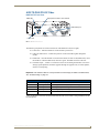
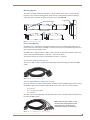
1
Instruction Manual
DGX Transmitters & Receivers
AVB-TX-DGX-HD15-SC Fiber
AVB-TX-DGX-DVI-SC Fiber
AVB-RX-DGX-SC Fiber-HD15
AVB-RX-DGX-SC Fiber-DVI
AutoPatch DGX Fiber Modules
REV C: 3/19/2010
AMX Limited Warranty and Disclaimer
This Limited Warranty and Disclaimer extends only to products purchased directly from AMX or an AMX Authorized
Partner which include AMX Dealers, Distributors, VIP’s or other AMX authorized entity.
AMX warrants its products to be free of defects in material and workmanship under normal use for three (3) years from
the date of purchase, with the following exceptions:
•
LCD Panels are warranted for three (3) years, except for the display and touch overlay components are
warranted for a period of one (1) year.
•
Disk drive mechanisms, pan/tilt heads, power supplies are warranted for a period of one (1) year.
•
AMX lighting products are guaranteed to switch on and off any load that is properly connected to our lighting
products, as long as the AMX lighting products are under warranty. AMX also guarantees the control of
dimmable loads that are properly connected to our lighting products. The dimming performance or quality
there of is not guaranteed, due to the random combinations of dimmers, lamps and ballasts or transformers.
•
AMX software is warranted for a period of ninety (90) days.
•
Batteries and incandescent lamps are not covered under the warranty.
•
AMX AutoPatch Epica, Modula, Modula Series 4, Modula Cat Pro Series and 8Y-3000 product models will be
free of defects in materials and manufacture at the time of sale and will remain in good working order for a
period of three (3) years following the date of the original sales invoice from AMX. The three-year warranty
period will automatically be extended to the life of the product (Limited Lifetime Warranty). The life of the
product extends until five (5) years after AMX ceases manufacturing the product model. The Limited Lifetime
Warranty applies to products in their original installation only. If a product is moved to a different installation,
the Limited Lifetime Warranty will no longer apply, and the product warranty will instead be the three (3) year
Limited Warranty.
REV E, Page 1 of 11, Effective Date 3-01-08
Note: The complete Warranty is at www.amx.com.
Contents
Contents
ESD Warning .......................................................................................................1
Important Safety Information and Instructions ....................................................2
Information et directives de sécurité importantes...............................................3
Notices ................................................................................................................4
Overview and Specifications ...............................................................................7
Applicability Notice ................................................................................................................. 7
Product Notes ......................................................................................................................... 7
AVB-TX-DGX-HD15-SC Fiber................................................................................................... 9
AVB-TX-DGX-DVI-SC Fiber .................................................................................................... 11
AVB-RX-DGX-SC Fiber-HD15................................................................................................. 13
AVB-RX-DGX-SC Fiber-DVI .................................................................................................... 15
DGX TX and DGX RX Specifications ...................................................................................... 17
Installation and Setup........................................................................................23
UL Safety Certifications, Notices, and Recommendations for Laser Products ....................... 23
Site Recommendations .......................................................................................................... 24
General Hazard Precautions .................................................................................................. 24
Setup Options ....................................................................................................................... 25
Basic Installation .................................................................................................................... 29
Addressing Special Installation Requirements ....................................................................... 35
Scaling Options .................................................................................................37
Auto Option (SmartScaleTM).................................................................................................. 38
Bypass Option ....................................................................................................................... 38
Manual Option and the Scaler Override Utility ..................................................................... 38
Adjusting Video with BoardConfig Software.....................................................45
System Requirements ............................................................................................................ 46
Determining Resolution and Refresh Rate for Source PC ...................................................... 47
Adjusting the Video Image with the DGX-HD15 Wizard ....................................................... 47
EDID Programmer .............................................................................................51
EDID Overview ...................................................................................................................... 51
Determining the Need for EDID Programming ..................................................................... 52
Installing the EDID Programmer ............................................................................................ 53
Reading and Saving EDID Data from the Destination Device................................................ 53
Writing EDID Data to the TX ................................................................................................. 55
Troubleshooting ................................................................................................57
DGX TX and DGX RX Troubleshooting.................................................................................. 57
Error Code Reporting (Power LED is Solid Amber) ............................................................... 62
Live Status Update Messages ................................................................................................ 63
Non-DGX Matrix Switcher Routing Behavior......................................................................... 64
Technical Support.................................................................................................................. 64
DGX Transmitters & Receivers Instruction Manual
i
Contents
Appendix A – Creating a Virtual Com Port ....................................................... 67
Establishing a Virtual Com Port ............................................................................................. 67
Identifying the Virtual Com Port............................................................................................ 69
Appendix B – Restoring Default Settings ......................................................... 71
Appendix C – Upgrading the Firmware ............................................................ 73
ii
DGX Transmitters & Receivers Instruction Manual
ESD Warning
ESD Warning
To avoid ESD (Electrostatic Discharge) damage to sensitive components, make sure you are properly
grounded before touching any internal materials.
When working with any equipment manufactured with electronic devices, proper ESD grounding
procedures must be followed to ensure people, products, and tools are as free of static charges as
possible. Grounding straps, conductive smocks, and conductive work mats are specifically designed for
this purpose.
Anyone performing field maintenance on AMX AutoPatch equipment should use an appropriate ESD
field service kit complete with at least a dissipative work mat with a ground cord and a UL listed
adjustable wrist strap with another ground cord. These items should not be manufactured locally, since
they are generally composed of highly resistive conductive materials to safely drain static charges,
without increasing an electrocution risk in the event of an accident. ESD protective equipment can be
obtained from 3M™, Desco®, Richmond Technology®, Plastic Systems®, and other such vendors.
DGX Transmitters & Receivers Instruction Manual
1
Important Safety Information and Instructions
Important Safety Information and Instructions
When using and installing your AMX AutoPatch product, adhere to the following basic safety
precautions. For more information about operating, installing, or servicing your AMX AutoPatch
product, see your product documentation.
Read and understand all instructions before using and installing AMX AutoPatch products.
Use the correct voltage range for your AMX AutoPatch product.
There are no user serviceable parts inside an AMX AutoPatch product; service should only be
done by qualified personnel.
If you see smoke or smell a strange odor coming from your AMX AutoPatch product, turn it
off immediately and call technical support.
For products with multiple power supplies in each unit, make sure all power supplies are
turned on simultaneously.
Use surge protectors and/or AC line conditioners when powering AMX AutoPatch products.
Only use a fuse(s) with the correct fuse rating in your enclosure.
Make sure the power outlet is close to the product and easily accessible.
Make sure the product is on or attached to a stable surface.
Turn off equipment before linking pieces together, unless otherwise specified in that product’s
documentation.
For safety and signal integrity, use a grounded external power source and a grounded power
connector.
To avoid shock or potential ESD (Electrostatic Discharge) damage to equipment, make sure
you are properly grounded before touching components inside an AMX AutoPatch product.
2
DGX Transmitters & Receivers Instruction Manual
Information et directives de sécurité importantes
Information et directives de sécurité
importantes
Veuillez vous conformer aux directives de sécurité ci-dessous lorsque vous installez et utilisez votre
appareil AMX AutoPatch. Pour de plus amples renseignements au sujet de l’installation, du
fonctionnement ou de la réparation de votre appareil AMX AutoPatch, veuillez consulter la
documentation accompagnant l’appareil.
Lisez attentivement toutes les directives avant d’installer et d’utiliser les appareils AMX
AutoPatch.
Le voltage doit être approprié à l’appareil AMX AutoPatch.
Les appareils AMX AutoPatch ne contiennent aucune pièce réparable par l’usager; la
réparation ne doit être effectuée que par du personnel qualifié.
Si de la fumée ou une odeur étrange se dégagent d’un appareil AMX AutoPatch, fermez-le
immédiatement et appelez le Service de soutien technique.
Veillez à ce que tous les blocs d’alimentation des appareils dotés de blocs d’alimentation
multiples dans chaque unité soient allumés simultanément.
Servez-vous de protecteurs de surtension ou de conditionneurs de lignes à courant alternatif
lorsque vous mettez les appareils AMX AutoPatch sous tension.
Placez uniquement des fusibles de calibre exact dans les boîtiers.
Veillez à ce que la prise de courant soit proche de l’appareil et facile d’accès.
Veillez à ce que votre appareil AMX AutoPatch soit installé sur une surface stable ou qu’il
y soit fermement maintenu.
Fermez toutes les composantes de l’équipement avant de relier des pièces, à moins
d’indication contraire fournie dans la documentation de l’appareil.
Par mesure de sécurité et pour la qualité des signaux, servez-vous d’une source d’alimentation
externe mise à la terre et d’un connect d’alimentation mis à la terre.
Pour éviter les chocs ou les dommages éventuels causés à l’équipement par une décharge
électrostatique, veillez à ce le dispositif oit bien relié à la terre avant de toucher les
composantes se trouvant à l’intérieur d’un appareil AMX AutoPatch.
DGX Transmitters & Receivers Instruction Manual
3
Notices
Notices
Copyright Notice
AMX© 2010 (Rev C), all rights reserved. No part of this publication may be reproduced, stored in a
retrieval system, or transmitted, in any form or by any means, electronic, mechanical, photocopying,
recording, or otherwise, without the prior written permission of AMX. Copyright protection claimed
extends to AMX hardware and software and includes all forms and matters copyrightable material and
information now allowed by statutory or judicial law or herein after granted, including without
limitation, material generated from the software programs which are displayed on the screen such as
icons, screen display looks, etc. Reproduction or disassembly of embodied computer programs or
algorithms is expressly prohibited.
No patent liability is assumed with respect to the use of information contained herein.
Liability Notice
While every precaution has been taken in the preparation of this publication, AMX assumes no
responsibility for error or omissions. No liability is assumed for damages resulting from the use of the
information contained herein.
Further, this publication and features described herein are subject to change without notice.
US FCC Notice
The United States Federal Communications Commission has specified that the following notice be
brought to the attention of the users of this product.
Federal Communication Commission Radio Frequency Interference Statement:
“This equipment has been tested and found to comply with the limits for a Class A digital device,
pursuant to Part 15 of the FCC Rules. These limits are designed to provide reasonable protection
against harmful interference when the equipment is operated in a commercial environment. This
equipment generates, uses, and can radiate radio frequency energy and, if not installed and used in
accordance with the instruction manual, may cause harmful interference to radio communications.
Operation of this equipment in a residential area is likely to cause harmful interference in which case
the user will be required to correct the interference at his own expense.
If necessary, the user should consult the dealer or an experienced radio/television technician for
additional suggestions. The user may find the booklet, How to Identify and Resolve Radio-TV
Interference Problems, prepared by the Federal Communications Commission to be helpful.”
This booklet is available from the U.S. Government Printing Office, Washington, D.C. 20402, Stock N.
004-000-00345-4.
Use shielded cables. To comply with FCC Class A requirement, all external data interface cables and
adapters must be shielded.
Lithium Batteries Notice
Switzerland requires the following notice for products equipped with lithium batteries. This notice is not
applicable for all AMX equipment.
Upon shipment of the products to Switzerland, the requirements of the most up-to-date Swiss Ordinance
Annex 4.10 of SR 814.013 will be met by providing the necessary documents and annual reports relative
to the disposal of the batteries to the Swiss Authorities.
4
DGX Transmitters & Receivers Instruction Manual
Notices
Trademark Notices
AMX®, AutoPatch®, NetLinx®, and SmartScale™ are trademarks of AMX.
Windows®, Windows 2000®, Windows NT®, and Windows XP Professional® are registered trademarks
of Microsoft Corporation.
HyperTerminal® is a copyright product of Hilgraeve Inc.
3M™, Desco®, Richmond Technology®, and Plastic Systems® are registered trademarks.
Neuron® and LonTalk® are registered trademarks of Echelon.
TosLink® is a registered trademark of the Toshiba Corporation.
Ethernet® is a registered trademark of the Xerox Corporation.
ENERGY STAR® is a registered trademark of the U.S. Department of Energy and the
U.S. Environmental Protection Agency
Other products mentioned herein may be the trademarks of their respective owners.
Warnings and Cautions
This manual uses the following conventions and icons to draw attention to actions or conditions that
could potentially cause problems with equipment or lead to personal risk.
ESD Warning: The icon to the left indicates text regarding potential danger associated with the
discharge of static electricity from an outside source (such as human hands) into an integrated
circuit, often resulting in damage to the circuit.
Warning: The icon to the left indicates text that warns readers against actions or conditions that
could cause potential injury to themselves.
Caution: The icon to the left indicates text that cautions readers against actions that could cause
potential injury to the product or the possibility of serious inconvenience.
DGX Transmitters & Receivers Instruction Manual
5
Notices
6
DGX Transmitters & Receivers Instruction Manual
Overview and Specifications
Overview and Specifications
Applicability Notice
The information in this manual applies to the four DGX Transmitter (TX) and Receiver (RX) modules
listed in the table below.
Important: These modules are compatible only with each other and with other AMX AutoPatch
DGX Signal Management products.
DGX TX and DGX RX Modules
FG #
Type
Model
Description
FG1010-200-01
TX
AVB-TX-DGHD15-SC Fiber
Analog video* + analog or digital audio over SC fiber
FG1010-210-01
TX
AVB-TX-DGX-DVI-SC Fiber
DVI video + analog or digital audio over SC fiber
FG1010-400-01
RX
AVB-RX-DGX-SC Fiber-HD15 SC fiber to RGBHV video + analog and digital audio
FG1010-410-01
RX
AVB-RX-DGX-SC Fiber-DVI
SC fiber to DVI video + analog and digital audio
* The supported analog video formats for this model TX are RGBHV, RGBS, RGsB, and Y/Pb/Pr video (Y/Pb/Pr
up to 1080p).
Product Notes
Either of the DGX Fiber TX modules listed can be paired with either of the DGX Fiber RX modules
as an end-to-end solution for transmission over single fiber or any of the modules can be used as an
integrated part of an AMX AutoPatch DGX matrix switcher that supports single fiber transmission.
This manual contains complete information for stand-alone use. For use in a system with a distribution
matrix, see page 25 in this manual and the distribution matrix’s Instruction Manual on the AMX
AutoPatch CD or at www.amx.com.
The following descriptions explain how the modules work as an end-to-end solution. The TX and RX
work in the same way when used in conjunction with DGX Fiber boards in a DGX matrix switcher.
DGX Fiber TX Modules – two types of transmitter modules are available, one model is for analog
signals and the other model is for a DVI signal. The analog module receives RGBHV, RGBS, RGsB, or
Y/Pb/Pr video signals, and the DVI Fiber module receives a DVI video signal from the source device.
The modules also receive either a digital audio signal or an analog stereo audio signal from the source
device (digital takes precedence if both are connected). Both the video and audio signals are transmitted
over an SC terminated fiber cable to a DGX RX module. The RS-232 port on each TX supplies
unidirectional RS-232 serial data over the SC terminated fiber cable with the data flow in the same
direction as the video signal. In addition to supporting transmission of incoming signals, the DGX TX
modules also include a local video output connector for sending the video signal directly from the source
to a local destination device.
DGX Fiber RX Modules – two types of receiver modules are available to accept the signal from a TX
module’s SC terminated fiber cable. The DGX HD-15 RX converts the video signal to RGBHV for the
destination device, and the DGX DVI RX converts the video signal to DVI for the destination device.
Both modules feature SmartScale™ (integrated EDID output scaling) to ensure appropriate output
resolution regardless of the type of incoming video. They also support a Manual (override) option for
setting up custom resolutions and a Bypass option. The audio on the RX is output on both the digital
audio port and the analog stereo audio port. The RS-232 port on each RX accepts any unidirectional
RS-232 serial data over the SC fiber from the TX.
DGX Transmitters & Receivers Instruction Manual
7
Overview and Specifications
DGX TX and DGX RX Module Features
Designed for use with single strand multimode fiber cable with SC connectors.
DGX technology provides a common signal transport and matrix switching layer that
transcodes between analog and digital signals; this allows compatibility among all the
DGX Fiber modules and with other AMX AutoPatch DGX Signal Management products.
Provides secure transmission of uncompressed DVI or RGBHV up to 3,000 feet (914 m) at
resolutions up to 1920x1200 @ 60 Hz, including 1080p. This distance applies to both ends
when modules are used in a system with a DGX Matrix Switcher’s Fiber boards.
Auto-Detect on the transmitters and SmartScale™ on the receivers work to automatically
recognize any device’s supported resolution and signal style parameters, allowing switching
out source devices and destination devices without manual setup.
SmartScale™ is the ability to configure the scaling output by automatically selecting
destination defined resolutions; the product also has the ability to control detailed timing
parameters for customized video output formats.
EDID support and integrated EDID output scaling, which scales any incoming signal to the
EDID declared preferred resolution of the attached destination (this feature can be overridden
or bypassed).
Custom EDID settings can be loaded on each input with the use of the included EDID
Programmer.
DGX HD-15 TX has the ability to detect an incoming analog signal (video or audio) and
automatically convert it to a digital signal (this feature can be overridden).
DGX HD-15 TX supports RGBHV, RGBS, RGsB, and Y/Pb/Pr (Y/Pb/Pr up to 1080p) video
formats.
DGX HD-15 RX supports an RGBHV video format.
DGX DVI TX and DGX DVI RX support a DVI video format.
Both TX modules accept analog stereo audio signals (unbalanced stereo) or digital audio
signals (PCM over S/PDIF @ 32 kHz, 44.1 kHz, 48 kHz). Analog stereo audio signals are
automatically converted to a digital signal.
Both RX modules send analog and digital audio signals.
Compare auto and manual video settings on the DGX HD-15 TX with the press of a button.
Supports progressive scanning (for optimal results) and interlaced scanning (for supported
resolutions, see page 19).
All modules support RS-232 port (3-position terminal block) unidirectional serial data from
source to destination.
Standard USB (mini-B) port can be used as a virtual Com port for serial communication with
a PC for overriding the AutoAD settings, adjusting the video signal with BoardConfig
software if necessary, making field upgrades (through an Upgrade Tool), and reporting errors.
BoardConfig software for the DGX HD-15 TX is available for user adjustable contrast,
brightness, and position.
Desktop power supply (ENERGY STAR® qualified) provided per module.
HD-15 to BNC breakout cable and HD-15 to RCA breakout cable are available.
Compatible with all V Style versatile mounting options including rack, surface, or pole.
Backed by AMX 3 year warranty (see www.amx.com or AMX AutoPatch CD).
24-hour technical support.
Note: Features and specifications described in this document are subject to change without notice.
8
DGX Transmitters & Receivers Instruction Manual
Overview and Specifications
AVB-TX-DGX-HD15-SC Fiber
DGX HD-15 TX Front View
Signal presence LEDs - Video & Audio
EDID LED
USB mini-B port
Power LED
Video Type LEDs
Mode (resolution) button & LEDs - Auto & Manual
FIG. 1 DGX HD-15 TX front view
The following components are located on the front of the DGX HD-15 TX (left to right):
Power LED – indicates whether or not the module is powered on.
Video and Audio LEDs – indicate the presence of video and audio signals through the
module.
EDID LED – when the module is in Write-Protect mode, the LED is off (default state); when
the module is in Write-Enable mode, the LED is green. The EDID switch is on the rear.
Video Type LEDs – indicate type of signal present: “Y/PB/PR, RGB” or “RGBHV, RGBS.”
Mode (resolution) button and Auto and Manual LEDs – use the Mode button to toggle
between Auto mode (the default mode) and Manual mode to view the difference on the
display when adjusting settings with BoardConfig.
USB mini-B port – connect to a control PC and use for overriding the automatic conversion
settings, signal adjustment, firmware upgrades through an Upgrade Tool, live status updates,
and error code reporting.
Important: If the indicator LEDs do not respond with a normal display as stated in the table below,
check all power connections before contacting technical support (see page 57).
TX Indicator LEDs
LED
Normal Display
Indicates
Power*
Constant green
Power is applied to module (initially red at start up).
Video
Constant green
A video signal is present through module.
Audio
Constant green
An audio signal is present through module.
EDID
Off
EDID is in Write-Protect mode (EDID switch on rear flipped down).
Y/PB/PR, RGB
Constant green
A Y/Pb/Pr or RGsB signal is present through module.
RGBHV, RGBS
Constant green
An RGBHV or RGBS signal is present through module.
Auto
Manual
One is constant green; Module is in Auto mode (default).
the other is off
Module is in Manual mode** (the mode for adjusting settings when
using BoardConfig).
* When a USB cable is connected, the Power LED blinks red while communication is being established with the
PC (see page 67).
** Other than when adjusting settings in BoardConfig, an illuminated Manual LED has no special significance as
the Auto and Manual settings are identical by nature once changes are saved.
DGX Transmitters & Receivers Instruction Manual
9
Overview and Specifications
DGX HD-15 TX Rear View
RS-232 (Serial Data Interface) Port
Video (HD-15) Local Output
Fiber (SC) Output
EDID W / WP Switch
& Sync Set B / A Switch
Power Jack
Video (HD-15) Input
Digital (RCA digital audio input) Stereo (3.5 mm analog stereo audio input)
FIG. 2 DGX HD-15 TX rear view
The following components are located on the rear of the DGX HD-15 TX (from left to right):
Power receptacle – a 2.1 mm DC jack for connecting power (an ENERGY STAR® qualified
desktop power supply is provided).
RS-232 (serial data interface) port – 3-position screw terminal block for unidirectional
data transfer from the source device to the destination device.
Video Input – HD-15 connector for an RGBHV video input signal.
Video Local Output – HD-15 connector for sending the video signal from the video input
connector to a local destination device.
Digital Audio – RCA jack for a digital audio input signal.
Stereo Audio – 3.5 mm jack for an analog stereo audio signal.
SC Fiber Output – accepts a standard 2.5 mm SC fiber connector (standardized in TIA-568A)
that snaps into place.
EDID switch – the default is set to WP (write protect), so source and destination can share
information; set to W for write enable. The EDID LED is on the front.
Sync Set switch – must be set to match the video format of the source signal (see page 32).
Special Product Information
If a video signal is not present on the TX, the lasers are disabled and will not transmit any video, audio,
or serial data to the RX.
A short lapse/drop of the serial data is to be expected under certain instances, e.g., when the digital audio
is unplugged or plugged or when the sample rate frequency of the digital audio changes.
10
DGX Transmitters & Receivers Instruction Manual
Overview and Specifications
AVB-TX-DGX-DVI-SC Fiber
DGX DVI TX Front View
Signal presence LEDs - Video & Audio
EDID LED
USB mini-B port
Power LED
FIG. 3 DGX DVI TX front view
The following components are located on the front of the DGX DVI TX (left to right):
Power LED – indicates whether or not the module is powered on.
Video and Audio LEDs – indicate the presence of video and audio signals through the
module.
EDID LED – when the module is in Write-Protect mode, the LED is off (default state); when
the module is in Write-Enable mode, the LED is green. The EDID switch is on the rear.
USB mini-B port – connect to a control PC and use for overriding the automatic conversion
settings, signal adjustment, firmware upgrades through an Upgrade Tool, live status updates,
and error code reporting.
Important: If the indicator LEDs do not respond with a normal display as stated in the table below,
see “Troubleshooting” on page 57.
TX Indicator LEDs
LED
Power*
Normal Display
Indicates
Constant green
Power is applied to module (initially red at start up).
Video
Constant green
A video signal is present through module.
Audio
Constant green
An audio signal is present through module.
EDID
Off
EDID is in Write-Protect mode (EDID switch on rear flipped down).
* When a USB cable is connected, the Power LED blinks red while communication is being established with the
PC (see page 67).
DGX Transmitters & Receivers Instruction Manual
11
Overview and Specifications
DGX DVI TX Rear View
RS-232 (Serial Data Interface) Port
Video (DVI) Local Output
Fiber (SC) Output
EDID W / WP Switch
Power Jack
Video (DVI) Input
Digital (RCA digital audio input) Stereo (3.5 mm analog stereo audio input)
FIG. 4 DGX DVI TX rear view
The following components are located on the rear of the DGX DVI TX (left to right):
Power receptacle – a 2.1 mm DC jack for connecting power (an ENERGY STAR® qualified
desktop power supply is provided).
RS-232 (serial data interface) port – 3-position screw terminal block for unidirectional
data transfer from the source device to the destination device.
Video Input – DVI-I connector for a DVI video input signal.*
Video Local Output – DVI-I connector for sending a DVI video signal to a local destination
device.*
Digital Audio – RCA jack for a digital audio input signal.
Stereo Audio – 3.5 mm jack for an analog stereo audio signal.
SC Fiber Output – accepts a standard 2.5 mm SC fiber connector (standardized in TIA-568A)
that snaps into place.
EDID switch – the default is set to WP (write protect), so source and destination can share
information; set to W for write enable. The EDID LED is on the front.
* DGX DVI Modules only support digital, single link (DVI-D) signals. The connectors on the module
are DVI-I connectors, which allow use of a cable with either a DVI-D or a DVI-I connector (for DVI-I,
the analog pins are not used; see the DVI-I connector pinout information on page 28). This also holds
true for DGX DVI Boards in DGX Matrix Switchers.
Special Product Information
If a video signal is not present on the TX, the lasers are disabled and will not transmit any video, audio,
or serial data to the RX.
A short lapse/drop of the serial data is to be expected under certain instances, e.g., when the digital audio
is unplugged or plugged or when the sample rate frequency of the digital audio changes.
12
DGX Transmitters & Receivers Instruction Manual
Overview and Specifications
AVB-RX-DGX-SC Fiber-HD15
DGX HD-15 RX Front View
USB mini-B port
Scaling button & LEDs - Bypass, Auto, & Manual
Power LED
Signal presence LEDs - Video & Audio
FIG. 5 DGX HD-15 RX front view
The following components are located on the front of the DGX HD-15 RX (left to right):
Power LED – indicates whether or not the module is powered on.
Video and Audio LEDs – indicate the presence of video and audio signals through the
module.
Scaling button and LEDs – use Scaling button to select one of the 3 Scaling options: Bypass,
Auto, or Manual.
USB port (mini-B) – connect to a control PC and use for overriding automatic conversion
settings, signal adjustment, if necessary, firmware upgrades through an Upgrade Tool, live
status updates, and error code reporting.
Important: If the indicator LEDs do not respond with a normal display as stated in the table below,
see “Troubleshooting” on page 57.
RX Indicator LEDs
LED
Power*
Normal Display
Constant green
Indicates
Power is applied to module.
Video
Constant green
A video signal is present through module.
Audio
Constant green
An audio signal is present through module.
Scaling – Bypass
– Auto (default)
– Manual
One is constant green;
the other two are off
Module is in one of the three modes for scaling.
At initial power up, the RX defaults to the Auto
Scaling option.**
Press Scaling button to turn on the Bypass option
or Manual option.
* When a USB cable is connected, the Power LED blinks red while communication is being established with the
PC (see page 67).
** If the output cable is disconnected from the RX or if no EDID can be found on the destination device, the
Bypass LED will be constant green and the Auto LED will blink. This indicates that the RX has switched to the
Bypass Scaling option and is waiting for EDID information. As soon as a valid EDID is found, the RX will revert to
the Auto Scaling option.
DGX Transmitters & Receivers Instruction Manual
13
Overview and Specifications
DGX HD-15 RX Rear View
SC Fiber Input
Stereo (3.5 mm analog stereo audio output)
Power Jack
RS-232 Port
HD-15 Output
Digital (RCA digital audio output)
FIG. 6 DGX HD-15 RX rear view
The following components are located on the rear of the DGX HD-15 RX (left to right):
Power receptacle – a 2.1 mm DC jack for connecting power (an ENERGY STAR® qualified
desktop power supply is provided).
RS-232 (serial data interface) port – 3-position screw terminal block accepts unidirectional
data transfer from the TX (source device to destination device).
Video Output – HD-15 connector for an RGBHV video output signal.
Digital Output – RCA jack for a digital audio output signal.
Stereo Output – standard 3.5 mm jack for an analog stereo audio output signal.
SC Fiber Input – accepts a standard 2.5 mm SC fiber connector (standardized in TIA-568A)
that snaps in.
Warning: Do not use the Stereo output connector as a headphone jack. The Stereo output is set at
unity gain (line-level) and is not intended for headphones.
Special Product Information
If a video signal is not present on the TX, the lasers are disabled and will not transmit any video, audio,
or serial data to the RX.
A short lapse/drop of the serial data is to be expected under certain instances, e.g., when the digital audio
is unplugged or plugged or when the sample rate frequency of the digital audio changes.
14
DGX Transmitters & Receivers Instruction Manual
Overview and Specifications
AVB-RX-DGX-SC Fiber-DVI
DGX DVI RX Front View
USB mini-B port
Scaling button & LEDs - Bypass, Auto, & Manual
Power LED
Signal presence LEDs - Video & Audio
FIG. 7 DGX DVI RX front view
The following components are located on the front of the DGX DVI RX (left to right):
Power LED – indicates whether or not the module is powered on.
Video and Audio LEDs – indicate the presence of video and audio signals through the
module.
Scaling button and LEDs – use Scaling button to select one of the 3 Scaling options: Bypass,
Auto, or Manual.
USB port (mini-B) – connect to a control PC and use for overriding automatic conversion
settings, signal adjustment, if necessary, firmware upgrades through an Upgrade Tool, live
status updates, and error code reporting.
Important: If the indicator LEDs do not respond with a normal display as stated in the table below,
see “Troubleshooting” on page 57.
RX Indicator LEDs
LED
Normal Display
Indicates
Power*
Constant green
Power is applied to module.
Video
Constant green
A video signal is present through module.
Audio
Constant green
An audio signal is present through module.
Scaling – Bypass
– Auto (default)
– Manual
One is constant green;
the other two are off
Module is in one of the three modes for scaling.
At initial power up, the RX defaults to the Auto
Scaling option.**
Press Scaling button to turn on the Bypass option
or Manual option.
* When a USB cable is connected, the Power LED blinks red while communication is being established with the
PC (see page 67).
** If the output cable is disconnected from the RX or if no EDID can be found on the destination device, the
Bypass LED will be constant green and the Auto LED will blink. This indicates that the RX has switched to the
Bypass Scaling option and is waiting for EDID information. As soon as a valid EDID is found, the RX will revert to
the Auto Scaling option.
DGX Transmitters & Receivers Instruction Manual
15
Overview and Specifications
DGX DVI RX Rear View
SC Fiber Input
Stereo (3.5 mm analog stereo audio output)
Power Jack
RS-232 Port
DVI Output
Digital (RCA digital audio output)
FIG. 8 DGX DVI RX rear view
The following components are located on the rear of the DGX DVI RX (left to right):
Power receptacle – a 2.1 mm DC jack for connecting power (an ENERGY STAR® qualified
desktop power supply is provided).
RS-232 (serial data interface) port – 3-position screw terminal block accepts unidirectional
data transfer from the TX (source device to destination device).
Video Output – DVI-I connector for a DVI video output signal.*
Digital Output – RCA jack for a digital audio output signal.
Stereo Output – standard 3.5 mm jack for an analog stereo audio output signal.*
SC Fiber Input – accepts a standard 2.5 mm SC fiber connector (standardized in TIA-568A)
that snaps in.
* DGX DVI Modules only support digital, single link (DVI-D) signals. The connector on the module is
a DVI-I connector, which allows use of a cable with either a DVI-D or a DVI-I connector (for DVI-I, the
analog pins are not used; see the DVI-I connector pinout information on page 28). This also holds true
for DGX DVI Boards in DGX Matrix Switchers.
Warning: Do not use the Stereo output connector as a headphone jack. The Stereo output is set at
unity gain (line-level) and is not intended for headphones.
Special Product Information
If a video signal is not present on the TX, the lasers are disabled and will not transmit any video, audio,
or serial data to the RX.
A short lapse/drop of the serial data is to be expected under certain instances, e.g., when the digital audio
is unplugged or plugged or when the sample rate frequency of the digital audio changes.
16
DGX Transmitters & Receivers Instruction Manual
Overview and Specifications
DGX TX and DGX RX Specifications
General Specifications
Parameter
Value
Approvals
UL, cUL, CE, FCC Class A, RoHS
AC Power
100 VAC to 240 VAC single phase, 50 Hz to 60 Hz
0.6 A @ 115 VAC max.
Power Consumption (max.)
+12 V, 1.25 A (15 W)
Thermal Dissipation (max.)
51 BTU/hr.
Power Connector*
2.1 mm DC power jack
Operational Temperature
32° F to 113° F (0° C to 45° C)
Storage Temperature
-22° F to 158° F (-30° C to 70° C)
Humidity
0 to 90% non-condensing
Dimensions
Depth
Width
Height
5.15 in. (13.08 cm)
5.80 in. (14.73 cm)
1.66 in. (4.22 cm), 1 RU
Weight
Approximately 1.75 lb. (0.8 kg) per module
Shipping Weight
Approximately 2.75 lb. (1.25 kg)
MTBF
92,000 hrs.
Safety Certifications
(DGX DVI TX and DGX HD-15 TX)
Class 1 Laser Product (Class 3R Laser Product when fiber is
disconnected from the unit) IEC 60825-1, 2001
* A desktop power supply (ENERGY STAR® qualified) is provided with each module.
Product Information Specifications
Parameter
Compatible AMX AutoPatch Products
Value
DGX HD-15 TX and RX, DGX DVI TX and RX,
Other AMX AutoPatch DGX Signal Management products
Resolution Support
640x480 @ 60 Hz up to 1920x1200 @ 60 Hz
Data Rate (max.)
4.95 Gbps
Pixel Clock
25 MHz to 165 MHz
Video Digital Processing
24 bit, 165 MHz
Input Interlaced Video Support
1080i 60, 59.94, 50 (fields/second); 576i 100 (fields/second)
Analog video only 576i 50 (fields/second); 480i 60 (fields/second)
Interlace video supported into the TX
Progressive only supported out of the RX
Video Propagation Delay (max.)
48 ms
Audio Propagation Delay (max.)
48 ms
Advanced Configuration Interface
USB Mini-B
Fiber Cable Type
Multimode Simplex (with SC termination)
50/125 μm (preferred) or 62.5/125 μm
Fiber Cable Length
Up to 3000 ft. (914.4 m) with 50 μm cable**
Up to 1500 ft. (457.2 m) with 62.5 μm cable
SC Cable Bend Radius (max.)
2 in. (5 cm)
Optical Budget
9.75 dBm (typical) between DGX TX and DGX RX
Optical Modulation Amplitude (OMA): -6.25 dBm (typical)
Optical Modulation Amplitude (OMA) Sensitivity: -16.0 dBm (typical)
Power Output of Laser Radiation (max.) 4.08 mW
(DGX DVI TX and DGX HD-15 TX only)
Fiber Connector
SC Optical
** 3,000 foot (914.4 m) cable requires 50/125 μm OM2 class low loss fiber cable. Transmission distance will vary
(more or less) depending on the type/quality of fiber used, fiber bandwidth, cable bend radius/kinks, splicing
quality and quantity, and chromatic or modal dispersion.
DGX Transmitters & Receivers Instruction Manual
17
Overview and Specifications
Compatibility Note: These modules are compatible only with each other (either TX to either RX)
and with other AMX AutoPatch DGX Signal Management products. DGX Fiber modules are not
compatible with third-party optical distribution amplifiers or multimode to single-mode converters.
Analog Video Specifications
TX
Input Signal Types
RGBHV, RGBS, RGsB, Y/Pb/Pr
Auto-Adjust Input
Yes
DDC/EDID Support
EDID provided by DGX TX
EDID is user re-programmable
RGB Input Signal Level Range
0 to 700 mVpp (0 to 750 mVpp max.)
RGB Input Impedance
75 ohm
HV Sync Input Signal Level Range
0 to +5 V
HV Sync Input Impedance
510 ohm
HV Sync Input Trigger Voltage
+1.75 V
Y/Pb/Pr Input Signal Level Range
1.0 Vpp for Y
700 mVpp for Pb Pr
Y/Pb/Pr Input Impedance
75 ohm
Input Connector
HD-15 (RGBHV and Y/Pb/Pr)
RGB Local Out Signal Level Range
0 to 700 mVpp (0 to 750 mVpp max.)
RGB Local Out Impedance
75 ohm
HV Sync Local Out Signal Level Range
0 to +5 V
HV Sync Local Out Impedance
50 ohm
Y/Pb/Pr Local Out Signal Level Range
1.0 Vpp for Y
700 mVpp for Pb Pr
Y/Pb/Pr Local Out Impedance
75 ohm
Local Output Connector
HD-15 (RGBHV and Y/Pb/Pr)
RX
18
Output Signal Type
RGBHV
Output Scaling
SmartScale™, Presets, Manual Configuration
RGB Output Signal Level Range
0 to 700 mVpp (0 to 750 mVpp max.)
RGB Output Impedance
75 ohm
HV Sync Output Signal Level Range
0 to +5 V
HV Sync Output Impedance
50 ohm
Output Connector
HD-15 (RGBHV)
DGX Transmitters & Receivers Instruction Manual
Overview and Specifications
DVI Video Specifications
TX
Input Signal Type
DVI-D (single link)
DDC/EDID Support
EDID provided by DGX TX
EDID is user re-programmable
HDCP Support
No
Input Voltage (nominal)
1.0 Vpp differential
Input Connector
DVI-I (DVI-D single link is the supported signal type)
DVI Local Out Nominal Voltage
1.0 Vpp differential
DVI Local Out Re-clocking (CDR)
Yes
DVI Local Out +5 V DDC Pin
50 mA
DVI Local Out Rise Time / Fall Time
75 ps min. to 240 ps max. (20% to 80%)
0.12 UI min. to 0.4 UI max. (@ 1.65 Gbps, 20% to 80%)
DVI Local Output Connector
DVI-I (DVI-D single link is the supported signal type)
Input Cable Length
Meets DVI spec of 5 m (16.4 ft.)
RX
Output Signal Type
DVI-D (single link)
Output Scaling
SmartScale™, Presets, Manual Configuration
Output Nominal Voltage
1.0 Vpp differential
Output Re-clocking (CDR)
Yes
Output +5 V DDC Pin
50 mA
Output Rise Time / Fall Time
75 ps min. to 240 ps max. (20% to 80%)
0.12 UI min. to 0.4 UI max. (@ 1.65 Gbps, 20% to 80%)
Output Connector
DVI-I (DVI-D single link is the supported signal type)
Resolution and Hz
EDID Specifications
TX Standard Timing Identification
ID 1
1920x1200 @ 60 Hz*
ID 2
1920x1080 @ 60 Hz
ID 3
1680x1050 @ 60 Hz
ID 4
1600x1200 @ 60 Hz
ID 5
1280x800 @ 60 Hz
ID 6
1280x720 @ 60 Hz
ID 7
1280x1024 @ 60 Hz
ID 8
640x480 @ 120 Hz
TX Established Timing
640x480 @ 60 Hz, 72 Hz, 75 Hz
800x600 @ 56 Hz, 60 Hz, 72 Hz, 75 Hz
1024x768 @ 60 Hz, 70 Hz, 75 Hz, 87 Hz
1280x1024 @ 75 Hz
* This is the preferred timing identified in the EDID.
DGX Transmitters & Receivers Instruction Manual
19
Overview and Specifications
Audio Specifications Table
Audio Specifications (Digital and Analog)
TX
Input Signal Types
Stereo analog, S/PDIF (2 Channel L-PCM)
Video signal must be present to pass audio
Analog Input Level (max.)
+8 dBu, unbalanced
Analog Input Impedance
2 kohms
S/PDIF Resolution
16 bit to 24 bit
S/PDIF Sample Rate
32 kHz, 44.1 kHz, 48 kHz, 96 kHz*
S/PDIF Input Signal Level Range
200 mVpp to 2.5 Vpp terminated
S/PDIF Input Impedance
75 ohm
Analog to Digital Reference Level
+8 dBu = 0 dBfs
Optimal Analog Audio Operating Range
-30 dBu to +8 dBu
Optimal Digital Audio Operating Range
-38 dBfs to 0 dBfs
Input Connectors
3.5 mm mini-stereo jack (analog stereo)
RCA jack (S/PDIF)
RX
Output Signal Types
Stereo analog, S/PDIF (2 Channel L-PCM)
Analog Output Level (max.)
+8 dBu, unbalanced
Analog Output Impedance
<5 ohm
Analog Output Frequency Response
<+/-0.3 dB, 20 Hz to 20 kHz
Analog Audio Output THD+N
<0.04%, 1 kHz, -10 dBu to +8 dBu
Analog Audio Out SNR
>92 dB, 20 Hz to 20 kHz, Vin = +8 dBu
S/PDIF Output Signal Amplitude
0.4 Vpp to 1.0 Vpp terminated into 75 ohm
S/PDIF Output Resolution
16 bit to 24 bit
S/PDIF Output Sample Rate
32 kHz, 44.1 kHz, 48 kHz, 96 kHz*
Digital to Analog Reference Level
0 dBfs = +8 dBu
Optimal Analog Audio Operating Range
-30 dBu to +8 dBu
Optimal Digital Audio Operating Range
-38 dBfs to 0 dBfs
Audio Synchronization
Progressive and interlace video formats @ 60 Hz frame rate;
audio is actively delayed to match video within 8 ms leading or
lagging
Output Connectors
3.5 mm mini-stereo jack (analog stereo)
RCA jack (S/PDIF)
* 96 kHz audio is only available when the source video resolution is 800x600 @ 60 Hz (40 MHz pixel clock) or
greater. Otherwise, the maximum is 48 kHz.
20
DGX Transmitters & Receivers Instruction Manual
Overview and Specifications
Serial Data Specifications
TX
Input Signal Type
Unidirectional RS-232: the control signal is transmitted in the same
direction as video/audio
Video signal must be present to pass serial data
Input Signal Level (max.)
+/-15 V
Baud Rate (max.)
115.2 k baud, 25 ft. (7.6 m) copper cable
Baud Rate (typical)
57.6 k baud, 150 ft. (45.7 m) copper cable
Input Connector
Pluggable 3.5 mm terminal block
RX
Output Signal Type
Unidirectional RS-232: the control signal is transmitted in the same
direction as video/audio
Output Signal Level (max.)
+/-5 V
Baud Rate (max.)
115.2 k baud, 25 ft. (7.6 m) copper cable
Baud Rate (typical)
57.6 k baud, 150 ft. (45.7 m) copper cable
Output Connector
Pluggable 3.5 mm terminal block
AMX reserves the right to modify its products and their specifications without notice.
DGX Transmitters & Receivers Instruction Manual
21
Overview and Specifications
22
DGX Transmitters & Receivers Instruction Manual
Installation and Setup
Installation and Setup
UL Safety Certifications, Notices, and Recommendations for Laser Products
Per UL requirements, make note of the following:
The DGX TX Fiber modules comply with IEC Standard: IEC 60825-1, 2001.
The modules also comply with 21 CFR 1040.10 and 1040.11 except for deviations pursuant
to Laser Notice No. 50, dated June 24, 2007.
The DGX TX Fiber modules are CLASS 1 LASER PRODUCTS.
The maximum output power of the laser radiation is 4.08 mW.
Since the class of radiation emitted from the fiber port can be Class 3R when the fiber cable or dust plug
is removed, a yellow and black label with the following caution is located on the top of each DGX TX
Fiber Module:
FIG. 9 Caution label for Class 3R laser products
Important: There are no user serviceable parts inside an AMX AutoPatch product; service should only
be done by qualified personnel.
Caution: Use of controls or adjustments or performance of procedures other than those specified
herein may result in hazardous radiation exposure.
Exercise caution when installing DGX products to avoid direct eye exposure to invisible laser radiation.
Follow the recommendations below whenever installing or working with DGX products.
Be sure to apply the power last, so that the fiber connector is not exposed when power is applied.
Do not remove dust plugs from SC fiber connectors or the dust caps from the fiber cables until
establishing connections; avoid direct eye exposure.
Ensure all cables, including fiber cables, are correctly connected and/or terminated.
If you need to unplug the fiber cable, be sure to unplug the power on the TX first.
DGX Transmitters & Receivers Instruction Manual
23
Installation and Setup
Site Recommendations
When placing the modules, follow the recommendations and precautions in this section to reduce potential
installation and operation hazards.
Environment
Choose a clean, dust free, (preferably) air-conditioned location.
Avoid areas with direct sunlight, heat sources, or high levels of EMI
(Electromagnetic Interference).
Module Accessibility
Make sure the front of each module is accessible, so that you can monitor the LED indicators. Leaving
adequate clearance at the rear will also allow for easier cabling and service.
Power
The source’s electrical outlet should be installed near the modules, easily accessible, and properly grounded.
Power should come from a building branch circuit. To avoid an overload, note the power consumption rating
of all the equipment connected to the circuit breaker before applying power.
General Hazard Precautions
These recommendations address potential hazards that are common to all installations:
Elevated Operating Temperature
The maximum rated ambient temperature for DGX Fiber modules is 113° F (45° C).
All equipment should be installed in an environment compatible with the manufacturer’s maximum rated
ambient temperature. In a closed or multi-unit rack assembly, the operating ambient temperature
of the rack environment may be greater than the ambient room temperature.
Caution: To protect the equipment from overheating, do not operate in an area that exceeds
113° F (45° C) and follow the clearance recommendation below for adequate airflow.
Airflow Restriction
The modules are designed to adequately dissipate the heat they produce under normal operating conditions;
however, this design is defeated when high heat producing equipment is placed directly above or below a
module.
Caution: To prevent overheating, avoid placing high heat producing equipment directly above or below
the modules. We recommend allowing one empty rack unit of clearance above the vent holes on top of
the modules.
Reliable Earthing (Grounding)
Reliable earthing of rack-mounted equipment should be maintained. If not using a direct connection
to the branch circuit (e.g., plugging into a power strip), pay particular attention to supply connections.
24
DGX Transmitters & Receivers Instruction Manual
Installation and Setup
Unpacking Tips
Before fully unpacking the module(s), inspect the shipping box(es) for any signs of damage.
If a box is partially crushed or any sides have been broken open, notify the shipping agency
immediately and contact your AMX representative (see the warranty on the
AMX AutoPatch CD or at www.amx.com).
Once unpacking is complete, closely check the physical condition of the module(s).
Collect all documentation.
Note: Please save the original shipping container and packing materials. AMX is not responsible
for damage caused by insufficient packing during return shipment to the factory. Shipping boxes
are available; contact your AMX representative for details.
Setup Options
This section covers options for system setup, mounting, and HD-15 cables (along with pinouts for the
HD-15 and DVI-I connectors on the modules).
DGX Fiber Modules with DGX Matrix Switcher System Setup Options
The following table contains four system setup options for using DGX Fiber modules in a standalone,
end-to-end solution and eight options for using them in conjunction with DGX Fiber boards in an
AMX AutoPatch DGX matrix switcher with DGX Fiber input and output boards.
System Setup Options – AMX AutoPatch Equipment between Source and Destination
Four Options
DGX Fiber modules
as a standalone,
end-to-end solution
DGX TX
DGX Matrix Switcher Input
Board
DGX Matrix Switcher
Output Board
HD-15 =
–
–
HD-15
HD-15 =
–
–
DVI
DVI =
–
–
HD-15
DVI
DVI =
HD-15 =
DVI =
Eight Options
DGX Fiber modules
in conjunction with
an AMX AutoPatch
DGX matrix switcher
DGX RX
–
–
Fiber =
Unspecified* =
Not Applicable
Not Applicable
Fiber =
Unspecified* =
Not Applicable
Unspecified* =
Fiber =
HD-15
Not Applicable
Unspecified* =
Fiber =
DVI
HD-15 =
Fiber =
Fiber =
HD-15
HD-15 =
Fiber =
Fiber =
DVI
DVI =
Fiber =
Fiber =
HD-15
DVI =
Fiber =
Fiber =
DVI
* To determine what types of input and output boards are compatible with DGX Fiber boards, see the matrix
switcher’s instruction manual.
Two system setups with DGX Fiber modules and a DGX Matrix Switcher are shown on the next page:
FIG. 10 shows a DGX TX and a DGX RX in an end-to-end solution.
FIG. 11 shows a DGX TX and a DGX RX used in conjunction with DGX Fiber boards in
a DGX matrix switcher.
The DGX HD-15 TX and the DGX DVI TX modules can be installed interchangeably. The DGX HD-15
RX and the DGX DVI RX modules are interchangeable as well, providing for an extremely flexible
system. For example, in the same system, the source device can send a DVI signal and the destination
device can receive an RGBHV signal.
DGX Transmitters & Receivers Instruction Manual
25
Installation and Setup
Control PC for setup –
only necessary for systems
with special requirements
Source Device
USB
USB
Destination Device
DGX RX
DGX TX
Fiber up to 3000 ft. (914 m)
FIG. 10 DGX TX and DGX RX modules in point-to-point solution
Control PC for setup –
only necessary for systems
with special requirements
Source Device
USB
USB
Destination Device
DGX RX
DGX TX
Fiber up to 3000 ft. (914 m)
on each side of matrix switcher
Matrix switcher with
DGX Fiber boards
FIG. 11 DGX TX and DGX RX modules in module-to-DGX Switcher-to-module solution
Note: When the system has special requirements, the DGX TX and the DGX RX can be connected
via the USB port to the Control PC for either setup scenario above.
DGX Fiber Modules with Non-DGX Matrix Switcher System Setup Options
A pair of DGX Fiber modules can be used upstream and/or downstream from a non-DGX matrix
switcher. For additional information on switching behavior with this type of system, see page 64.
Control PC for setup –
only necessary for systems
with special requirements
Source Device
USB
USB
DGX RX
Destination Device
DGX TX
DGX RX
Non-DGX
matrix switcher
Fiber up to 3000 ft. (914 m)
between each DGX TX and
DGX RX pair
DGX TX
FIG. 12 DGX TX and DGX RX modules in module pair-to-non-DGX switcher-to-module pair solution
Note: When the system has special requirements, any of the DGX TX and the DGX RX modules
can be connected via the USB port to the Control PC for this setup scenario.
26
DGX Transmitters & Receivers Instruction Manual
Installation and Setup
Mounting Options
The DGX TX and RX modules are classified as V Style modules, which require V Style mounting
hardware. These versatile mounting options include rack trays and mounting brackets for desktops,
under desks, poles, and walls. For details on kit options, see www.amx.com.
Rack tray with spacer
Pole mounts
Mounting brackets
FIG. 13 V Style mounting hardware
HD-15 Cable Options
DGX HD-15 TX – Although any of the following cables (which are available through AMX) can be
used to connect the source device to the HD-15 connector on the TX, we recommend using an HD-15 to
HD-15 cable for the best display results.
DGX HD-15 RX – Either the HD-15 to HD-15 cable or the HD-15 with 5 BNCs breakout cable can be
used to connect the destination device to the HD-15 connector on the RX.
The pinout for the HD-15 connector on the modules is in FIG. 17 on page 28.
HD-15 to HD-15 Cable (FG10-2170-01)
The HD-15 to HD-15 cable is available from AMX and provides the best display results for RGBHV
signals.
FIG. 14 HD-15 to HD-15 cable, 6 ft. (1.83 m)
HD-15 to 5 BNC Breakout Cable (FG10-2170-05)
DGX TX – The HD-15 to 5 BNC breakout cable is normally used for an RGBHV signal. If you are using
this breakout cable to send a Y/Pb/Pr signal from the source device to the TX, connect as follows:
Pr to red
Y to green (sync signal)
Pb to blue
DGX RX – When connecting the RX to the destination device, HD-15 to 5 BNC breakout cable can only
be used for RGBHV signals.
Note: When this type of cable is used,
the RX cannot read the EDID from the
destination device, resulting in the
SmartScale™ feature not functioning.
FIG. 15 HD-15 to 5 BNC breakout cable, 6 ft. (1.83 m)
DGX Transmitters & Receivers Instruction Manual
27
Installation and Setup
3 RCA Breakout Cable
HD-15 to 3 RCA Breakout Cable (FG10-2170-03)
This cable is available from AMX and can be used for either Y/Pb/Pr or RGsB signals from the source
device to the TX. The connection information is the same as the HD-15 to 5 BNC breakout cable.
Note: This cable cannot be used with an RX, as
the RX can only send an RGBHV signal to the
destination.
FIG. 16 HD-15 to 3 RCA breakout cable, 6 ft. (1.83 m)
HD-15 Pinout
The pinout in FIG. 17 is for the HD-15 connectors on DGX HD-15 TX and DGX HD-15 RX
modules.
FIG. 17 DGX HD-15 TX (input and local output) and DGX HD-15 RX (output) pinout
Note: 55 mA is supplied on output pin 9; power draw not to exceed 50 mA per port.
DVI Pinout
The pinout in FIG. 18 is for the DVI-I connectors on DGX DVI TX and DGX DVI RX modules.
FIG. 18 DGX DVI TX (input and local output) and DGX DVI RX (output) pinout
* The +5 VDC on output pin 14 on the DGX DVI RX module supplies a maximum of 55 mA.
28
DGX Transmitters & Receivers Instruction Manual
Installation and Setup
Basic Installation
Installation Scenario 1 (Basic) Automatic Image Adjustment and Automatic EDID Scaling
The flow chart in FIG. 19 assumes that the results from the automatic image adjustment and automatic
EDID scaling require no further adjustment.
Basic Installation
TX
Attach
connectors
Apply power
RX
Attach
connectors
Apply power
DGX HD-15 TX only
Set the A/B
Sync Set switch
FIG. 19 Basic installation procedure – assumes image is satisfactory
For most installations, the following basic installation steps will provide a satisfactory image on the
destination device. If the installation has special requirements, three additional scenarios are presented at
the end of the basic installation steps which indicate how to handle them. Depending on the installation’s
requirements, one or more of the three scenarios could apply.
Safety Recommendations for Laser Products
Important: There are no user serviceable parts inside an AMX AutoPatch product; service should
only be done by qualified personnel.
Caution - Use of controls or adjustments or performance of procedures other than those specified
herein may result in hazardous radiation exposure.
Exercise caution when installing DGX products to avoid direct eye exposure to invisible laser radiation.
Follow the recommendations below whenever installing or working with DGX products.
Be sure to apply the power last, so that the fiber connector is not exposed when power is
applied.
Do not remove dust plugs from SC fiber connectors or the dust caps from the fiber cables until
establishing connections; avoid direct eye exposure.
Ensure all cables, including fiber cables, are correctly connected and/or terminated.
If you need to unplug the fiber cable, be sure to unplug the power on the TX first.
TX – Attaching Signal Cables
Check When Fastening Fiber Cable:
Ensure that there is no dust or debris on the exposed ends of the fiber cable.
Ensure that the fiber cable connectors seat firmly into the module’s fiber connector. Normally
an audible click is heard when a connector engages.
Caution: Do not severely bend or kink the fiber cable. It can cause irreversible damage to the cable.
The bend radius for AMX fiber cables is 2 inches (5 cm).
Note: If an interlaced video format is sent to a TX, the RX will output a progressive video format,
regardless of the scaling mode.
DGX Transmitters & Receivers Instruction Manual
29
Installation and Setup
To attach signal cables to a TX:
Digital audio
EDID switch must be set to WP
HD-15 cable
SC fiber cable
Analog stereo audio cable
Digital audio
EDID switch must be set to WP
SC fiber cable
DVI cable
Analog stereo audio cable
FIG. 20 Attach signal cables to DGX HD-15 TX (top) or DGX DVI TX (bottom)
1.
Check the EDID switch on the rear of the TX to be sure that it remains in the down position for
WP (write protect).
2.
DGX HD-15 TX – Attach the connector on the HD-15 cable from the source device to the Video Input
receptacle (FIG. 20, top). HD-15 connectors on the module use the pinout information in FIG. 17.
or
DGX DVI TX – Attach the connector on the DVI cable from the source device to the Video Input
receptacle (FIG. 20, bottom). DVI connectors on the module use the pinout information in FIG. 18.
3.
Optional – To use the local out option for a nearby video destination device, attach the device’s cable to
the Local Video Output receptacle.
4.
If needed – Insert the connector on the digital or analog stereo audio cable from the source device into
the appropriate input audio jack, Digital or Stereo. Digital takes precedence if both are connected.
CAUTION – CLASS 3R INVISIBLE LASER RADITION WHEN OPEN; AVOID DIRECT EYE EXPOSURE.
5.
Clean the fiber cable connector. Follow the manufacturer’s recommendations.
6.
Remove the dust plug from the SC Fiber Output jack* and insert the fiber cable connector (the fiber
connector will click when fully engaged).
7.
Connect the open end of the SC fiber cable to the RX before connecting power.
* The fiber jack is a standard 2.5 mm SC fiber connector (standardized in TIA-568A) that snaps the cable
connector into place.
30
DGX Transmitters & Receivers Instruction Manual
Installation and Setup
TX – Wiring for RS-232 Data Transfer
The RS-232 port is a unidirectional interface.
Important: The RS-232 connection on the modules requires management of the RS-232 data line in
relation to switching operations. In an upstream matrix switching scenario, we recommend that
RS-232 control commands (via the DGX RS-232 data connection) are not sent immediately prior or
subsequent to a matrix switching command. It is possible for the RS-232 data to be corrupted as the
video (or audio) signal is removed and then restored by the matrix switcher.
The RS-232 port is the 3- position screw terminal block on the rear of the module to the right of the power
jack. Wire this port to supply unidirectional RS-232 serial data along with the associated video and audio
signals from a source device (via the TX over fiber to the RX) to a destination device. The video signal
must be present to pass serial data.
On the TX module, the pinout for the RS-232 connector is “RX - Ground - NC.” The RS-232 port label is
relative to the data flow; RS-232 data flows the same direction as the video signal. Data enters the system
at the RX label on the TX module and leaves the system at the TX label on the RX module.
To wire the RS-232 port on the TX for data transfer:
1.
Wire the RS-232 connector according to the pinout directly above the connector (FIG. 21).
RS-232 pinout
FIG. 21 Wire TX for RS-232 data transfer
TX – Applying Power
Caution: If you are providing the power supply, use a UL (or equivalent) listed power supply.
To avoid damage to the module, the electrical ratings for the power supply must not exceed those
indicated in the “Specifications” table on page 17.
To apply power to the TX:
tables for LEDs at initial power up
1.
Plug the cord from the desktop power supply (provided) into the power jack on rear of the TX.
2.
Plug the desktop power supply into an AC external power source.
The Power LED on the front of the TX initially turns red and after a moment it turns a constant green,
indicating a ready state.
Some of the additional LEDs will also turn a turn a constant green; see the table below for LED states
on initial power up.
DGX HD-15 TX – Indicator LEDs at Initial Power Up
TX LED
Normal State
Indicates
Power
Constant red
Constant green
Initial application of power (red for a brief time only).
Power is in an operational state.
Video
Constant green
A video signal is present through TX.
Audio
Constant green
An audio signal is present through TX.
EDID
Off
EDID is in Write-Protect mode (EDID switch on rear is flipped down).
Y/PB/PR, RGB
Constant green
A Y/Pb/Pr or RGsB signal is present through TX.
RGBHV, RGBS
Constant green
An RGBHV or RGBS signal is present through TX.
Auto
Manual
Constant green
Off
TX is in Auto mode for determining resolution (default state).
Press Mode button to turn on Manual mode (Auto LED will turn off).
DGX Transmitters & Receivers Instruction Manual
31
Installation and Setup
DGX DVI TX – Indicator LEDs at Initial Power Up
TX LED
Normal State
Indicates
Power
Constant red
Constant green
Initial application of power (red for a brief time only)
Power is in an operational state
Video
Constant green
A video signal is present through TX
Audio
Constant green
An audio signal is present through TX
EDID
Off
EDID is in Write-Protect mode (EDID switch on rear is flipped down)
For information on restoring the TX default settings on power up, see page 71.
DGX HD-15 TX Only – Check and Set Switch for Video Signal Type
When the DGX HD-15 TX is powered up, it is normally in Auto mode and will detect whatever type of
signals are coming from the source device. The Sync Set dip switch on the rear must be set to
position A (down) or position B (up) to match the type of incoming video signal. The default setting is
the Sync Set switch in position A.
To check type of video signal DGX HD-15 TX is receiving and set Sync Set dip switch:
1.
Check the Video Type LED indicators on the front of the TX.
If the RGBHV, RGBS indicator is green, the Sync Set dip switch can be either in position A or B.
If the Y/PB/PR, RGB indicator is green, the toggle switch must be in the correct position for the
specific signal (to determine setting, see the table below).
2.
Set the Sync Set dip switch to position A (down) or B (up) according to the type of incoming signal.
3.
Cycle power.
Note: The dip switch can be set to either A or B for RGBHV or RGBS signals.
Signal Type
Sync Set Switch
Position A (down)
Sync Set Switch
Position B (up)
Y/Pb/Pr
RGsB
RGBS
RGBHV
Note: If the video cable is disconnected (or the source signal is turned off), the illuminated Signal
Type LED will turn off. If the cable is reconnected (or the source signal is turned back on), the
indicator will turn green again.
RX – Attaching Signal Cables
Check When Fastening Fiber Cable:
Ensure that there is no dust or debris on the exposed ends of the fiber cable.
Ensure that the fiber cable connectors seat firmly into the module’s fiber connector. Normally
an audible click is heard when a connector engages.
Caution: Do not severely bend or kink the fiber cable. Irreversible damage can occur. The bend
radius for AMX fiber cables is 2 inches (5 cm).
32
DGX Transmitters & Receivers Instruction Manual
Installation and Setup
Digital audio
SC fiber cable
HD-15 cable
Analog stereo audio cable
Digital audio
SC fiber cable
DVI cable
Analog stereo audio cable
FIG. 22 Attach signal cables to DGX HD-15 RX (top) or DGX DVI RX (bottom)
To attach signal cables to the RX:
1.
Attach the connector for the HD-15 cable for the destination device to the Video Output receptacle.
HD-15 connectors on the module use the pinout information in FIG. 17.
2.
If needed – Insert the connector for the digital and/or analog stereo audio cable for the destination device
into the appropriate audio Output jack, Digital or Stereo. The audio signal is output on both ports.
CAUTION: CLASS 3R INVISIBLE LASER RADITION WHEN OPEN; AVOID DIRECT EYE EXPOSURE.
3.
Clean the fiber cable connector; follow the manufacturer’s recommendations.
4.
Remove the dust plug from the SC Fiber Output jack* and insert the fiber cable connector (the fiber
connector will click when fully engaged).
5.
Be sure the other end of the SC fiber cable is connected before applying power.
* The fiber jack is a standard 2.5 mm SC fiber connector (standardized in TIA-568A) that snaps the cable
connector into place.
RX – Wiring for RS-232 Data Transfer
The RS-232 port is a unidirectional interface, which is compatible only with other AMX AutoPatch products
that use the single fiber interface.
The RS-232 port is the 3-position screw terminal block on the rear of the module to the right of the power
jack. Wire this port to supply unidirectional RS-232 serial data along with the associated video and audio
signals from a source device (via the TX over fiber to the RX) to a destination device. The video signal must
be present to pass serial data.
On the RX module, the pinout for the RS-232 connector is “NC - Ground - TX.” The RS-232 port label is
relative to the data flow; RS-232 data flows the same direction as the video signal. Data enters the system at
the RX label on the TX module and leaves the system at the TX label on the RX module.
DGX Transmitters & Receivers Instruction Manual
33
Installation and Setup
To wire the RS-232 port on the RX for data transfer:
1.
Wire the RS-232 connector according to the pinout directly above the connector (FIG. 23).
RS-232 pinout
FIG. 23 Wire RX for RS-232 data transfer
RX – Applying Power
Caution: If you are providing the power supply, use a UL (or equivalent) listed power supply.
To avoid damage to the module, the electrical ratings must not exceed those indicated in the
“Specifications” table on page 17.
To apply power to the RX:
1.
Plug the cord from the desktop power supply (provided) into the power jack on rear of the RX.
2.
Plug the desktop power supply into an AC external power source.
The Power LED on the front of the RX initially turns red and after a moment it turns a constant
green, indicating a ready state.
Some of the additional LEDs will also turn a turn a constant green; for LED states on initial power
up, see the table below.
DGX HD-15 RX and DGX DVI RX – Indicator LEDs at Initial Power Up
RX LED
Power
Normal State
Constant red
Constant green
Indicates
Initial application of power (red for a brief time only).
Power is in an operational state.
Video
Constant green
A video signal is present through the RX.
Audio
Constant green
An audio signal is present through the RX.
Scaling – Bypass
– Auto
– Manual
Off
Constant green*
Off
At initial power up, the RX defaults to the Auto Scaling
option.*
Press Scaling button to turn on the Bypass option or Manual
option.
* If the output cable is disconnected from the RX or if no EDID can be found on the destination device, the
Bypass LED will be constant green and the Auto LED will blink. This indicates that the RX has switched to the
Bypass Scaling option and is waiting for EDID information. As soon as a valid EDID is found, the RX will revert to
the Auto Scaling option.
For information on restoring the RX default settings on power up, see page 71.
34
DGX Transmitters & Receivers Instruction Manual
Installation and Setup
Addressing Special Installation Requirements
For most installations, the basic installation steps just covered will provide a satisfactory image on the
destination device. If the installation has special requirements (or in some cases when the TX is used in
conjunction with a DGX matrix switcher), three additional scenarios are presented which indicate how
to handle them. The information necessary to complete these scenarios is covered in the chapters
referenced under each scenario. Depending on the installation, one or more of the scenarios may apply.
Note: Scenarios 2 and 3 each require the creation of a virtual Com port (see page 67)
to run the necessary software, which is available on the AMX AutoPatch CD and at www.amx.com.
Installation Scenario 2 – Automatic Image Adjustment and Custom Scaling
When a specific or a custom resolution is desired, the flow chart in FIG. 24 shows the sequence to
follow. Complete the instructions for “Basic Installation” starting on page 29, and then see the “Scaling
Options” chapter on page 37 for detailed information on the scaling modes and the scaling override
procedure (applies to both the DGX HD-15 RX and the DGX DVI RX).
Basic Installation
TX
Attach
connectors
Apply power
DGX HD-15 TX only
Set A/B
Sync Set switch
Scaling Override Procedure
RX
Attach
connectors
Apply power
PC
Connect to PC
& establish
virtual Com port
Open Scaler
Override utility &
set resolution
FIG. 24 Installation procedure with override for setting a resolution
Installation Scenario 3 – Manual Image Adjustment and Automatic EDID Scaling
When fine tuning of the image is desired, the flow chart in FIG. 25 shows the sequence to follow.
Complete the instructions for “Basic Installation” starting on page 29, and then see the “Adjusting Video
with BoardConfig Software” chapter on page 45 for detailed information on the video adjustment
procedure (applies only to the DGX HD-15 TX).
Basic Installation
DGX HD-15 TX only
Attach
Apply power
connectors
RX
Attach
connectors
Video Adjustment Procedure
Set A/B
Sync Set switch
Control PC
Connect to PC
& establish
virtual Com port
Open
BoardConfig &
fine tune image
Apply power
FIG. 25 Installation procedure with manual image adjustment
DGX Transmitters & Receivers Instruction Manual
35
Installation and Setup
Installation Scenario 4 – Automatic Image Adjustment Using Custom EDID
When you need to read a custom EDID from the destination device and write it to the TX,
the flow chart in FIG. 26 shows the sequence to follow. Complete the instructions for “Basic Installation”
starting on page 29, and then see the “EDID Programmer” chapter on page 51 for detailed information
on the procedure for reading the EDID from a destination device and writing it to the TX (applies to both
the DGX HD-15 TX and the DGX DVI TX).
Read and Write EDID Procedure
PC
Connect PC to
destination device
Open EDID
Programmer &
read EDID from
detected device
Basic Installation
TX
Attach
connectors
RX
Attach
connectors
Apply power
DGX HD-15 TX only
Set A/B
Sync Set switch
Connect cable
from PC to TX
Video Input
connector
Flip EDID switch
to W & use EDID
Programmer to
write EDID to TX;
flip switch to WP
Apply power
FIG. 26 Installation procedure using EDID Programmer to read and write EDID
36
DGX Transmitters & Receivers Instruction Manual
Scaling Options
Scaling Options
Applicability
This chapter deals with the SmartScale™ feature (controlled through the Auto option) on both the
DGX HD-15 RX and the DGX DVI RX, as well as Bypass and Manual (the other two Scaling options).
The section on the Manual Scaling option provides an overview of the Scaler Override utility along with
instructions for setting a specific resolution or a custom resolution.
Important: Because the basic installation steps normally produce a satisfactory image, you will not
need the information in this chapter unless the installation has special requirements.
Installation Scenario 2 – Automatic Image Adjustment and Custom Scaling
The flow chart in FIG. 27 shows the sequence to follow when the installation requires a specific or a
custom resolution.
To complete the “Basic Installation,” see page 29.
To establish a virtual Com port, see page 67.
To use the Scaler Override utility (available on the AMX AutoPatch CD or at www.amx.com),
see page 38.
TX
Attach
connectors
Basic Installation
Apply power
DGX HD-15 TX only
Set A/B
Sync Set switch
Apply power
PC
Connect to PC
& establish
virtual Com port
Scaling Override Procedure
RX
Attach
connectors
Open Scaler
Override utility &
set resolution
FIG. 27 Installation procedure – override for setting a resolution
Scaling Options Overview
The RX automatically uses the EDID of the destination device to scale (SmartScale™ technology).
The scaling feature supports from 25 MHz to 165 MHz pixel clock (the maximum resolution is
1920x1200 @ 60 Hz).
The Scaling button on the front of the DGX RX is used to switch between the Auto (SmartScale™),
Bypass, and Manual options. The options for Scaling cycle from Auto (default) to Manual to Bypass.
Tip: After you save the settings in the Scaler Override utility, use the Scaling button to cycle through
the options to compare the resulting video displays for the Auto and Manual options.
Persistence of a Scaling Option
The factory default is for the RX to revert to the Auto option if power is cycled. If you want the RX to
remain in either Manual or Bypass when power is cycled, use the following instructions.
To persist a Scaling option on power cycle:
1.
Press and release the Scaling button until the LEDs cycle to the option immediately before the one
you want to persist.
2.
Press and hold the Scaling button about 5 seconds until the desired LED blinks green, indicating
that option will persist on power cycle.
DGX Transmitters & Receivers Instruction Manual
37
Scaling Options
Auto Option (SmartScaleTM)
In most cases, selecting the DGX HD-15 RX and DGX DVI RX Auto option (default) provides a
satisfactory image on the destination monitor or device. In this case, no other action is required.
Note: The Auto option automatically persists when the power is cycled on the RX, unless the
persisted state has been changed (see page 37).
Bypass Option
If the Auto option does not provide a satisfactory image on the monitor, the Bypass option can be
selected with the Scaling button. When Bypass is selected, any modifications to the video signal
generated on a DGX HD-15 TX or DGX DVI TX (see page 45) are left unmodified by the RX, i.e., the
signal leaves the RX exactly as it came into the RX.
To keep in mind regarding the Bypass option:
When adjusting a TX with Board Config software, setting the RX to the Bypass option is
recommended if the display will support the desired resolution (see page 47).
If the RX fails to read the EDID on power up (i.e., no resolution data is available from the
destination device), the RX reverts to the Bypass option until the video cable is unplugged and
then plugged in, at which time it will attempt to read the EDID again.
Note: When Bypass mode is selected, an interlaced source changes to a progressive output.
To select the Bypass option on the RX:
1.
Press the Scaling button on the RX once or twice (depends on current selection) until the Bypass
LED illuminates solid green.
Note: If you want this option to persist when the power is cycled on the RX, see page 37.
Manual Option and the Scaler Override Utility
In some special installation cases, you will need to select Manual on the DGX RX to override the
automatic scaling and set (configure) a specific or a custom resolution for the display monitor. When a
DGX RX is connected to a PC running the Scaler Override utility, the utility displays the resolutions
supported by the destination monitor based on the set of supported resolutions in the monitor’s (or other
destination device’s) EDID. Settings can then be selected and applied to the RX.
When you select Manual, the RX sets up the video scaler with factory default values (1280x1024
@ 60 Hz). EDID preferred resolution parameters are used if available, unless scaler setup parameters
were previously uploaded.
Important: If a device with an EDID (e.g., a video processor) is installed between the RX and
destination monitor, the Scaler Override utility will read the EDID for that device. If this happens,
you will probably need to set a custom resolution.
Note: When the following timings are in the EDID data, the Scaler Override utility will not display
them: 720x400 @ 70 Hz, 720x400 @ 88 Hz, 640x480 @ 67 Hz, 832x624 @ 75 Hz, and
1152x870 @ 75 Hz. These timings can be entered in the utility as custom resolutions.
PC Requirements
Windows XP Professional®
Minimum Hardware: 166 MHz, 128 MB RAM, 20 MB free disk space*, 800x600 display
Recommended Hardware: 2.0 GHz, 512 MB RAM
USB port**
* The installation process requires 20 MB of disk space for the Scaler Override installer. Once installed,
the tool requires 5 MB of disk space.
** For DGX Fiber modules, the USB port is used as a virtual Com port for serial communication.
38
DGX Transmitters & Receivers Instruction Manual
Scaling Options
How the Scaler Override Utility Works
Important: If breakout cables are used between the DGX HD-15 RX and the destination monitor (or
device), the Scaler Override utility cannot read the EDID.
When the Scaler Override utility is launched, it attempts to obtain the EDID information from the
destination monitor. One of the following occurs:
If the utility finds the EDID information, it populates the interface with the appropriate
“preferred/native” resolution settings (and fills in the advanced timing section with the
corresponding data).
If the utility cannot find the EDID information, it populates the interface with the Standard
timing default settings (and fills in the advanced timing section with the corresponding data).
Important: On start up, the Scaler Override utility’s interface always reflects one of the two conditions
mentioned above; it does not show the settings currently stored on the RX, unless you use the utility
to retrieve them from the RX. This holds true even if you persist the Manual Scaling option (see
page 37).
The Scaler Override utility can then be used to do any of the following:
Set the Aspect Ratio option to either Maintain Aspect Ratio or Stretch to Fit. Click Save to
persist this setting to the Manual and Auto options. (For descriptions of these settings, see
page 44.)
Set an EDID that is read from the detected device (basic resolution); see (A) on page 40.
Set a standard preset, which applies standard timing; see (B) on page 41.
Set a custom resolution with the option of applying advanced detailed timing parameters;
see (C) on page 42.
Retrieve the settings from an RX; see page 43.
Save the settings in the utility to a file; see page 43.
Load the timings from a file to the utility and apply them to an RX; see page 43.
Note: When retrieving or loading a timing, the program will automatically display “Custom” as the
selected Resolution Source and “Advanced” as the selected Timing Mode regardless of the original
source of the timing.
Utility Menu Options
File Menu – Save Timing to File (saves the settings displayed on the utility to a file), Load
Timing from File (loads settings from a file to the utility), and Exit.
Communication Menu – Refresh EDID Info (from the destination device) and Retrieve Current
Timing* (from the RX).
* The current timings displayed will depend on the selected Scaling option. If the RX is in Auto, the utility
reflects the current timings chosen by the SmartScale™ technology. If the RX is in Manual, the utility
reflects the currently applied timings (not necessarily the settings stored in memory).
Time Saving Tip: When a number of RX modules are connected to the same type of destination
devices, the menu options can be used to retrieve the settings from one RX, save those settings to a
file, and then load the settings to additional RX modules.
Apply, Save, and Close Options
Apply – Use to try out settings. Sends currently displayed settings to RX; does not store or
persist settings.
Save – Use to preserve currently displayed settings. Sends currently displayed settings to RX to
store them; sends command to persist settings in the RX memory (also persists Manual Scaling
option on the RX).
Close – Closes the application without sending or saving any changes in the settings. (If Apply
was just selected, the utility asks whether or not to save the applied settings.)
DGX Transmitters & Receivers Instruction Manual
39
Scaling Options
Before starting the Scaler Override procedure (applies to either DGX RX):
Connect the DGX RX to a PC using a USB (mini-B) cable (FG10-5965 provided).
A virtual Com port must be established; see page 67.
On the PC, install the Scaler Override utility from the AMX AutoPatch CD
(<CDDrive>:\Configuration\ScalerOverride) or from www.amx.com).
Option A
(A) To set an EDID for the RX from the detected device:
Note: If the Manual option is not selected in Step 1, the RX automatically goes to the Manual option
when the utility is opened or when either the Apply or the Save button in the utility is selected. (If the
Save button is selected, the Manual option persists when power is cycled on the RX.) The Manual option
remains selected until the Scaling button on the RX is pressed to activate another option.
1.
Press the Scaling button on the RX once or twice (depends on the current selection) until the Manual
LED illuminates green.
2.
Open the Scaler Override utility (it automatically queries the destination device for EDID information).
The EDID Status section indicates that the EDID information has been found for the detected device or
that a list of standard resolutions is available).
Select EDID
FIG. 28 Scaler Override utility with EDID selected
3.
Under Aspect Ratio, click either Maintain Aspect Ratio or Stretch to Fit (for descriptions of both, see
page 44).
4.
Under Resolution Source, click EDID.
5.
Under EDID from Detected Device, select desired resolution from the Available Display Modes list.
6.
Click Apply to transmit the selected information to the RX. This action is temporary (and you can still
cycle through the Scaling options on the RX); settings are not stored on the RX until Step 8; otherwise,
the settings last only until power is cycled. The display re-syncs with the module.
7.
Verify that the display is satisfactory before proceeding.
8.
Click Save* to store the currently displayed settings (if the setting have been changed since clicking
Apply, the newest settings will be saved) on the RX and persist them in memory. (The RX will power up
in the Manual option.)
* If you click Close instead of Save immediately after applying settings, the utility asks if you want to save
prior to exiting. Selecting Yes applies the settings, persists them on the RX, persists the Manual mode on the
RX over power cycles, and closes the utility. Selecting No closes the utility; the applied settings are still in
effect and can be accessed under the Manual option. However, they are not stored on the RX and on power
cycle, the RX will revert to its previously stored settings.
40
DGX Transmitters & Receivers Instruction Manual
Scaling Options
Option B
(B) To set to a standard preset for the RX:
Note: If the Manual option is not selected in Step 1, the RX automatically goes to the Manual option
when the utility is opened or when either the Apply or the Save button in the utility is selected. (If the
Save button is selected, the Manual option persists when power is cycled on the RX.) The Manual
option remains selected until the Scaling button on the RX is pressed to activate another option.
1.
Press the Scaling button on the RX once or twice (depends on the current selection) until the Manual
LED illuminates green.
2.
Open the Scaler Override utility (it automatically queries the destination device for EDID
information). The EDID Status section indicates either that the EDID information has been found for
the detected device or that a list of standard resolutions is available).
Select Standard
Standard Presets / Timing Mode includes:
DMT (Discrete Monitor Timing)
GTF (General Timing Formula)
CVT (Coordinated Video Timing)
CVT-RB (Coordinated Video Timing Reduced Blanking)
CEA (Consumer Electronics Association)
Standard 861D for HDTV
FIG. 29 Scaler Override utility with standard resolution selected
3.
Under Aspect Ratio, click either Maintain Aspect Ratio or Stretch to Fit (for descriptions of both, see
page 44).
4.
Under Resolution Source, click Standard.
5.
Under Standard Presets, select the timing mode from the Timing Mode list and select the resolution
from the Available Display Modes list.
6.
Click Apply to transmit the selected information to the RX. This action is temporary (and you can
still cycle through the Scaling options) until the settings are stored on the RX in Step 8; otherwise, the
settings last only until power is cycled. The display re-syncs with the module.
7.
Verify that the display is satisfactory before proceeding.
8.
Click Save* to store the currently displayed settings (if the setting have been changed since clicking
Apply, the newest settings will be saved) on the RX and persist them in memory. (The RX will power
up in the Manual option.)
* If you click Close instead of Save immediately after applying settings, the utility asks if you want to
save prior to exiting. Selecting Yes applies the settings, persists them on the RX, persists the Manual
mode on the RX over power cycles, and closes the utility. Selecting No closes the utility; the applied
settings are still in effect and can be accessed under the Manual option. However, they are not stored on
the RX and on power cycle, the RX will revert to its previously stored settings.
DGX Transmitters & Receivers Instruction Manual
41
Scaling Options
Option C
(C) To set a custom resolution for the RX with optional advanced timing parameters:
Note: If the Manual option is not selected in Step 1, the RX automatically goes to the Manual option
when the utility is opened or when either the Apply or the Save button in the utility is selected. (If the
Save button is selected, the Manual option persists when power is cycled on the RX.) The Manual
option remains selected until the Scaling button on the RX is pressed to activate another option.
1.
Press the Scaling button on the RX once or twice (depends on the current selection) until the Manual
LED illuminates green.
2.
Open the Scaler Override utility (it automatically queries the destination device for EDID
information). The EDID Status section indicates either that the EDID information has been found for
the detected device or that a list of standard resolutions is available.
Select Custom
Custom Resolution / Timing Mode includes:
Advanced / Advanced Timing Parameters display
GTF (General Timing Formula)
CVT (Coordinated Video Timing)
CVT-RB (Coordinated Video Timing - Reduced Blanking)
Select Show Timing Details (for Advanced Timing Parameters)
FIG. 30 Scaler Override utility with a Custom Resolution selected (left) and Advanced Timing Parameters selected (right)
42
3.
For Aspect Ratio, click either Maintain Aspect Ratio or Stretch to Fit (for descriptions of both, see
page 44).
4.
Under Resolution Source, click Custom.
5.
Under Custom Resolution, enter the width, height, and refresh rate.
6.
Select the timing mode from the Timing Mode list.
If Advanced is selected from the list (FIG. 30, on the right), the Advanced Timing Parameters section
opens; complete all remaining steps.
If another timing mode is selected from the list (FIG. 30, on the left), go to Step 8.
7.
Advanced only – under Horizontal Geometry, enter the values in pixels. Under Vertical Geometry,
enter the values in lines. Select HSync and VSync Polarity.
8.
Click Apply to transmit the selected information to the RX. This action is temporary (and you can still
cycle through the Scaling options) until the settings are stored on the RX in Step 10; otherwise, the
settings last only until the power is cycled. The display re-syncs with the module.
9.
Verify that the display is satisfactory before proceeding.
DGX Transmitters & Receivers Instruction Manual
Scaling Options
10. Click Save* to store the currently displayed settings (if the setting have been changed since clicking
Apply, the newest settings will be saved) on the RX and persist them in memory. (The RX will
power up in the Manual option.)
* If you click Close instead of Save immediately after applying settings, the utility asks if you want to
save prior to exiting. Selecting Yes applies the settings, persists them on the RX, persists the Manual
mode on the RX over power cycles, and closes the utility. Selecting No closes the utility; the applied
settings are still in effect and can be accessed under the Manual option. However, they are not stored on
the RX and on power cycle, the RX will revert to its previously stored settings.
Note: Downscaling to 800x600 – When using the Scaler Override utility to scale from 1280x1024
down to 800x600, occasionally the video changes to a solid color screen and needs to be reset to
restore the image. Auto Scaling is recommended when possible.
Retrieving, Saving, and Loading Settings
Time Saving Tip: When a number of RX modules are connected to destination devices of the same
type, the menu options can be used to retrieve the settings from one RX, save those settings to a
file, and then load the settings to another RX.
Note: When retrieving or loading a timing, the program will automatically display “Custom” as the
selected Resolution Source and “Advanced” as the selected Timing Mode regardless of the original
source of the timing.
To retrieve the settings from an RX:
1.
From the Communications menu, select Retrieve Current Timing.
To save the settings in the utility to a file:
1.
From the File menu, select Save Timing to File.
To load the timings from a file to the utility and then apply them to an RX:
1.
From the File menu, select Load Timing from file.
2.
Click Apply to transmit the loaded timing to the RX. This action is temporary (and you can still
cycle through the Scaling options) until the settings are stored on the RX in Step 4; otherwise, the
settings last only until power is cycled. The display re-syncs with the module.
3.
Verify that the display is satisfactory before proceeding.
4.
Click Save* to store the currently displayed settings (if the setting have been changed since clicking
Apply, the newest settings will be saved) on the RX and persist them in memory. (The RX will
power up in the Manual option.)
* If you click Close instead of Save immediately after applying settings, the utility asks if you want to
save prior to exiting. Selecting Yes applies the settings, persists them on the RX, persists the Manual
mode on the RX over power cycles, and closes the utility. Selecting No closes the utility; the applied
settings are still in effect and can be accessed under the Manual option. However, they are not stored on
the RX and on power cycle, the RX will revert to its previously stored settings.
DGX Transmitters & Receivers Instruction Manual
43
Scaling Options
Maintain Aspect Ratio and Stretch to Fit
Maintain Aspect Ratio (default) – This option maintains the incoming video’s aspect ratio, but will
scale the image until the display’s video fills either the horizontal or vertical direction first. If the vertical
direction is filled first, then the video will have pillar box black bars on the sides of the display (display
on left in FIG. 31). If the horizontal direction is filled first, then the video will have letter box black bars
on the top and bottom of the display.
Stretch to Fit – This option scales the video to fill the display in both the horizontal and vertical
directions (display on right in FIG. 31). Black bars do not show when Stretch to Fit is selected.
FIG. 31 Example of displays set to Maintain Aspect Ratio and Stretch to Fit
Important: If changing the Aspect Ratio setting to Stretch to Fit is the only change you need to make
with the Scaler Override utility, select the option and click Save. Stretch to Fit will now persist to the
Manual and Auto options.
44
DGX Transmitters & Receivers Instruction Manual
Adjusting Video with BoardConfig Software
Adjusting Video with BoardConfig Software
Applicability
This chapter applies only to the DGX HD-15 TX module and covers manual adjustment for fine tuning
an image. BoardConfig software is provided for manually adjusting the video image, if necessary.
Important: Because the basic installation steps (see page 29) normally produce a satisfactory
image, you will not need the information in this chapter unless the installation has special
requirements.
Installation Scenario 3 – Manual Image Adjustment and EDID Scaling
The flow chart in FIG. 32 shows the sequence when fine tuning of the image is desired.
To complete the “Basic Installation,” see page 29.
To establish a virtual Com port, see page 67.
To use BoardConfig software (available on the AMX AutoPatch CD or at www.amx.com),
see page 47.
Basic Installation
DGX HD-15 TX only
Attach
Apply power
connectors
Video Adjustment Procedure
Set A/B
Sync Set switch
Control PC
Connect to PC
& establish
virtual Com port
Open
BoardConfig &
fine tune image
RX
Attach
connectors
Apply power
FIG. 32 Installation procedure – adjust image with BoardConfig
The input signal from the source to the TX may need to be adjusted to obtain an optimal display at the
destination. Board configuration software, the DGX-HD15 Wizard, is provided on the AMX AutoPatch CD
(<CDDrive>:\Configuration\BoardConfig\DGX-HD15) and at www.amx.com for this purpose.
DGX Transmitters & Receivers Instruction Manual
45
Adjusting Video with BoardConfig Software
System Requirements
Control PC
Windows 2000® or Windows XP Professional®
Minimum Hardware: 166 MHz, 128 MB RAM, 20 MB free disk space*, 800x600 display
Recommended Hardware: 2.0 GHz, 512 MB RAM, 20 MB free disk space*, 1024x768 display
USB port**
* The installation process requires 20 MB of disk space for the BoardConfig installer. Once installed, the
tool requires 5 MB of disk space.
** For DGX Fiber modules, the USB port is used as a virtual Com port for serial communication.
The Control PC runs the DGX-HD15 Wizard software, which adjusts the source’s video signal as it is
viewed on the Destination Monitor. The TX is connected to a Control PC via the USB port. Once system
setup is complete and no further changes to the display are necessary, you can disconnect the Control PC.
Source PC (or any other RGB or Y/Pb/Pr video source)
The TX is connected to the Source PC via an HD-15 cable. If the Source PC does not have a video card
that supplies RGBHV, RGBS, RGsB, or Y/Pb/Pr video format signals at one of the resolution and refresh
rates in the table below, BoardConfig software can be used. To determine the resolution and refresh rate
for the Source PC, see page 47.
Resolution
Refresh Rate
640x480
60 Hz, 72 Hz, 75 Hz, 120 Hz
800x600
56 Hz, 60 Hz, 72 Hz, 75 Hz
1024x768
60 Hz, 70 Hz, 75 Hz, 87 Hz
1280x720
60 Hz
1280x800
60 Hz
1280x1024
60 Hz, 75 Hz
1600x1200
60 Hz
1680x1050
60 Hz
1920x1080
60 Hz
1920x1200
60 Hz (This is the preferred timing identified in the EDID.)
Important: If the device’s EDID does not fall within the default resolution parameters provided (check
the EDID timing specifications on page 19), see the “EDID Programmer” chapter on page 51 before
adjusting the video with the DGX-HD15 Wizard.
Destination Monitor
The Destination Monitor is connected to the HD-15 connector on the DGX HD-15 RX or the DVI
connector on the DGX DVI RX. Adjustments made with the wizard are seen on the Destination Monitor.
Test Image Files
Test image files for specific resolutions for viewing when adjusting the display are provided on the AMX
AutoPatch CD (<CDDrive>:\Configuration\BoardConfig\Test Patterns). Test image files are opened* on
the Source PC and subsequently display on the Destination Monitor.
* Adobe Acrobat Reader is required to view the test image .pdf files. Acrobat Reader is a free program
available online at www.adobe.com.
46
DGX Transmitters & Receivers Instruction Manual
Adjusting Video with BoardConfig Software
Determining Resolution and Refresh Rate for Source PC
The instructions below assume that the basic installation has been completed and the DGX HD-15 TX
has been connected to the Source PC. Before attempting to adjust the video display with the
DGX-HD15 Wizard, verify the resolution and refresh rate on the Source PC using the following
instructions.
To determine video card resolution/refresh settings on Windows© operating systems:
1.
Minimize all applications on the Source PC.
2.
Right click on the desktop.
3.
Select Properties from the shortcut menu.
4.
In the Display Properties dialog box, select the Settings tab.
5.
Check the Screen resolution setting; write it down (e.g., 1280 by 1024 pixels).
6.
Click Advanced.
7.
Select the Monitor tab.
8.
Check the Screen refresh rate (or frequency); write it down (e.g., 60 Hertz).
If the refresh rate setting is not located under the Monitor tab, try selecting the other available tabs.
9.
Click Cancel on each dialog box to exit.
Adjusting the Video Image with the DGX-HD15 Wizard
Important: This procedure works only on the DGX HD-15 TX module.
The DGX-HD15 Wizard can be used for adjusting the video image for a DGX HD-15 TX module. This
wizard displays embedded Help (information at the bottom of the screen) and also includes a standard
Help file with detailed information.
Important: Do not change the video input while in the process of using the DGX-HD-15 Wizard.
Pre-Adjustment Tasks
Before starting the adjustment procedure, the following pre-adjustment tasks must be completed:
If the system contains an RX – We recommend selecting the Bypass option on the RX (press
the Scaling button once or twice until the Bypass LED illuminates solid green; return to the
desired option when the video adjustments are complete).
Connect the Control PC to the TX via the USB port (a virtual Com port must be established;
see page 67). A USB mini-B cable, FG10-5965, is provided.
Install the DGX-HD15 Wizard on the Control PC by running the BoardConfig.exe file on the
AMX AutoPatch CD (<CDDrive>:\Configuration\BoardConfig\DGX-HD15) or from
www.amx.com. We recommend uninstalling any versions of BoardConfig software prior to
v1.4.0 first.
Transfer the test image files from the Control PC to the Source PC.
Determine the resolution and refresh rate of the Source PC (see instructions above).
Place the Destination Monitor within view of the Control PC, so you can see the effect of the
adjustments.
DGX Transmitters & Receivers Instruction Manual
47
Adjusting Video with BoardConfig Software
Adjustment Tips:
Be sure the source device that is sending the signal to the Display Monitor (or device)
has a sharp picture before you start.
The Destination Monitor controls may also need adjusting during the video display
adjustment procedure with the wizard.
CRT monitors seem more sensitive to losing sync when changing vertical position.
“ReSync Monitor” under the Options menu can be useful when closing in on the final settings.
Sometimes re-syncing will clear up small irregularities in the display.
Watch the sync / no sync light on the Destination Monitor. Dramatic movements in a setting
can cause the monitor to go blank temporarily because it loses sync. As long as the
adjustments are in the acceptable range for the Destination Monitor, the sync light will shine
constant a few seconds before the image reappears. If the sync light does not shine constant,
return to the previous setting.
Note: The TX automatically goes into Manual mode when adjustments are made in BoardConfig.
To adjust the video display using the DGX-HD15 Wizard:
1.
Complete the “Pre-Adjustment Tasks” list on the previous page.
2.
Open the DGX-HD15 Wizard.
FIG. 33 DGX-HD15 Wizard
48
3.
Use the File\Open menu and select the supplied resolution file (<installation folder>\
presets\defaults\) that matches or closely matches the Source PC’s settings.
(The .xml file name consists of the resolution followed by the refresh rate. If not indicated, the
refresh rate is the default of 60 Hz).
4.
Select the Horizontal Resolution icon. Verify that the value above the scroll bar matches the
horizontal value of the resolution. If necessary, move the scroll bar as close as possible to the correct
value. Then click either scroll arrow until the value is exact. For example, for a resolution of
1280x960 move the scroll bar as close to 1280 as possible; then click a scroll arrow until the value
is exactly 1280.
5.
Select the Vertical Resolution icon and repeat the previous step for the vertical value of the
resolution.
DGX Transmitters & Receivers Instruction Manual
Adjusting Video with BoardConfig Software
Important: After the resolution values have been verified, further adjustments may not be required.
If this is the case, go to Step 9 to complete the procedure.
6.
On the Source PC, open the test image PDF that matches the resolution setting.
If an image does not appear, change the Source PC’s video card settings to match one of the
supported resolutions (see the “EDID Specifications” table on page 19).
7.
Select the Horizontal Total Pixels icon. Adjust one step at a time (click on either scroll arrow),
watching the vertical noise lines (bands) on the Destination Monitor mover farther apart. Stop when
the bands disappear.
8.
If needed, adjust the rest of the icons keeping the following tips in mind:
Horizontal Position
CRT screens may need to use the screen controls to fine tune for size and position.
If not working, try adjusting Horizontal Pulse Width first and then retry.
Vertical Position
CRT screens will often go blank for a moment on each adjustment.
To quickly make large adjustments to CRT screens, use the Page Up / Page Down keys.
Horizontal Pulse Width
The default normally works well for higher resolutions.
For lower resolutions that do not fit the display well, try increasing the value.
Reduced blanking resolutions (>1600x1200) require a small value.
Tip: Use the Mode button to toggle between Auto and Manual to compare the resulting video
displays.
9.
From the Options menu, select Save to System (to restore settings upon power up).
The Save to System dialog box opens.
10. Click OK.
The custom BoardConfig settings are now part of Auto mode and will be used any time that
customized format is detected.
11. Recommended – From the File menu, select Save As to save a backup file to the Control PC.
Enter a file name, and click Save.
12. Close BoardConfig and toggle the Mode button to Auto.
13. If the system has an RX – If the RX was set to Bypass as part of the pre-adjustment tasks on
page 47, press and release the Scaler button to select the desired option.
14. Disconnect the Control PC when finished.
Note: If the settings are customized again and saved, the new custom settings will overwrite the
current custom settings. To restore the default settings, see page 71.
DGX Transmitters & Receivers Instruction Manual
49
Adjusting Video with BoardConfig Software
50
DGX Transmitters & Receivers Instruction Manual
EDID Programmer
EDID Programmer
Applicability
This chapter applies to both the DGX HD-15 TX and the DGX DVI TX modules and covers reading the
EDID from the destination device and writing the EDID to the TX.
Important: Because the basic installation steps normally produce a satisfactory image, you will not
need the information in this chapter unless the installation has special requirements or in some
cases when a DGX TX is used in conjunction with a DGX matrix switcher.
EDID Programmer software is provided for in-field re-programming of the EDID EEPROM chips on the
DGX TX module if necessary.
Installation Scenario 4 – Automatic Image Adjustment Using Custom EDID
The flow chart in FIG. 34 shows the sequence when a custom EDID is read from the destination device
and written to a DGX TX.
To complete the “Basic Installation,” see page 29.
To install and use the EDID Programmer (available on the AMX AutoPatch CD or at
www.amx.com), see page 53.
Read and Write EDID Procedure
PC
Connect PC to
destination device
Open EDID
Programmer &
read EDID from
detected device
Basic Installation
TX
Attach
connectors
RX
Attach
connectors
Apply power
DGX HD-15 TX only
Set A/B
Sync Set switch
Connect cable
from PC to TX
Video Input
connector
Flip EDID switch
to W & use EDID
Programmer to
write EDID to TX;
flip switch to WP
Apply power
FIG. 34 Installation procedure – Read and Write EDID using EDID Programmer
EDID Overview
EDID (Extended Display Identification Data) is a data structure established by the Video Electronics
Standards Association (VESA) to enable plug-and-play support by enabling easy configuration of
a computer’s graphics subsystem based on the capabilities of the attached display device.
EDID information includes items such as the following:
Manufacturer’s name
Product type
Supported video resolutions and refresh rates
Color space and filter chromaticity
Detailed timings
When a computer is directly connected to a display device, it can use the display device’s EDID
information to determine an initial compatible video signal to send. With the computer’s display
controls, the user can modify this selection to another compatible signal based on the provided EDID
information.
DGX Transmitters & Receivers Instruction Manual
51
EDID Programmer
DGX TX Modules and EDID
As long as the source signal being transmitted is supported by the display device, the result should be a
good image on the display. If the source signal being transmitted is not supported by the display device,
the result will be either a badly distorted image or no image at all.
To address these issues, the DGX TX comes with an EDID EEPROM chip for the input connector,
which has been pre-loaded with an AMX AutoPatch EDID set. This EDID set consists of 24 of the most
common EDID settings in use today, including all VESA Established Timings encompassing 8
resolutions at a variety of refresh rates and 8 additional Standard Timings encompassing 8 resolutions
and refresh rate combinations (for timing details, see page 19). In almost all cases, the DGX TX can be
used straight out of the box with no adjustments (see “Determining the Need for EDID Programming”
on page 52).
The EDID Programmer software has been provided for cases where additional in-field re-programming
of the EDID chip is needed. EDID Programmer software can be used for the following:
Reading and saving EDID data from a device
Writing EDID data to a DGX TX input connector’s associated EDID EEPROM
Note: Any analysis or editing of the EDID data necessary to support the equipment specific to your
installation will need to be done separately prior to using the EDID Programmer. A variety of
freeware tools can be found on the web to help with these tasks.
The remaining sections provide information on:
Determining the need for EDID programming
Installing the EDID Programmer
Reading and saving EDID data from a destination device
Writing data to the DGX TX
Determining the Need for EDID Programming
Ideally the EDID analysis will have been completed during installation specification. If this was not
possible but the system’s devices are now available, the most effective way to proceed is to test if the
signal from the source device can be transmitted through the DGX TX and RX to the destination device.
If the signal can be routed (i.e., the image is present), then EDID programming is not necessary.
To determine if EDID programming is necessary:
1.
Install the DGX TX and RX according to the installation procedure starting on page 29.*
2.
Check the destination display to verify that the picture is present.
If the picture is not present, see “Troubleshooting” on page 57 before proceeding.
Note: If the destination does not display a picture, analysis or editing of the EDID data may be
necessary prior to using the EDID Programmer. A variety of freeware tools can be found on the web
to help with these tasks.
* If a DGX TX and a DGX RX are used in conjunction with a DGX matrix switcher, install the modules
and the matrix switcher and then route the video signal to verify that the picture is present on the
destination(s). (The system could also include just a TX or an RX depending on the boards in the matrix
switcher; for setup options, see page 25.)
52
DGX Transmitters & Receivers Instruction Manual
EDID Programmer
Installing the EDID Programmer
PC Requirements (EDID Programmer v1.2.0)
Windows 2000® or Windows XP Professional®
Minimum Hardware: 166 MHz, 128 MB RAM, 20 MB of free disk space*, 800x600 display,
video card with dual outputs**
Recommended Hardware: 2.0 GHz, 512 MB RAM
Serial port
* The installation process requires 20 MB of disk space for the EDID Programmer installer. Once
installed, the EDID Programmer requires 5 MB of disk space.
** We strongly urge the user not to use video cards with DMS-59 connectors. Video cards with DMS-59
connectors have been shown to fail consistently and, in the worst case, can corrupt an EDID data file.
A laptop PC with a VGA or DVI out is a good solution. Cards with 2 DVI connectors, 2 VGA
connectors, or 1 DVI and 1 VGA connector are also acceptable.
To install EDID Programmer software:
1. Locate and open the installer <EDIDProgrammer_1.2.exe> on the AMX AutoPatch CD
(<CDDrive>:\Configuration\EDIDProgrammer) or at www.amx.com.
2.
Follow the directions in the wizard.
Reading and Saving EDID Data from the Destination Device
Tip: The Save button in the EDID Programmer can be used to save the EDID information as an.edid
file, which can be opened as a text file (click the Open button) and edited or opened and written to
the Video input on the TX (click the Write button).
The instructions on page 54 cover the situation in which the EDID Programmer is used to read the EDID
information from a destination device in the installation using a DVI connector (an HD-15connector can
also be used). Additional information for using DVI cable is provided below.
Using Cable Adapters
If your laptop has an HD-15 (VGA) port, you can use a DVI-to-VGA cable to connect the laptop’s
HD-15 video port to a DVI cable attached to a destination device’s DVI port. Alternatively, use the
following combination of adapters with a DVI-D cable to connect the laptop to the destination device:
PC or
Laptop
Female VGA (HD-15) adapter
to Male DVI-I adapter
DVI-I Female to
DVI-Female adapter
Male DVI-D to
Male DVI-D cable
Destination
Device
FIG. 35 Connecting an HD-15 (VGA) port to a DVI port
Note: The setup of adapters and DVI-D cable in FIG. 35 passes EDID information but does not pass
video signals.
DGX Transmitters & Receivers Instruction Manual
53
EDID Programmer
To read and save EDID data from the destination:
1.
On the PC, open the EDID Programmer.
Communication menu – use to select PC serial port or change baud rate
Target Device – select Accessory Module
Query AutoPatch Device – acquires XNNet ID address of device
EDID Information – data (read-only) from file or display device
Available Displays drop down list – select device
EDID Type – indicates analog or digital (read-only)
Refresh Display List – updates list after additional devices attached
Convert to Digital / Convert to Analog – converts displayed EDID data
Status – shows application status (read-only)
Close – shuts down application; will not prompt to save
Open – an EDID file
Save – an EDID file to edit or to write to input on module
Write – writes EDID to input on module
Read – reads EDID from selected destination device
54
2.
Connect a DVI cable to the PC using the PC’s spare monitor port (for cable options for this step, see
“Using Cable Adapters” on page 53).
3.
Connect the open end of the DVI video cable to the destination device (typically a monitor) from
which the EDID information needs to be read.
4.
Click the Refresh Display List button to update the Available Displays drop down list.
5.
From the Available Displays drop down list, select the destination device from which you need to
read the EDID.
6.
Click the Read button to read the EDID information. The results display in the read-only area.
7.
Click the Save button (select location, enter file name, and click Save).
Leave the EDID Programmer open for the instructions on writing the EDID to the TX on the next
page.
8.
Disconnect the DVI cable from the PC and from the destination device.
DGX Transmitters & Receivers Instruction Manual
EDID Programmer
Writing EDID Data to the TX
DGX HD-15 TX
The instructions that follow cover the situation in which the EDID Programmer is used to write EDID
information to the EDID chip for the Video Input connector on a previously unprogrammed
DGX HD-15 TX using an HD-15 cable.
DGX DVI TX
The instructions that follow can be adapted to cover the situation in which the EDID Programmer is used
to write EDID information to the EDID chip for the Video Input connector on a previously
unprogrammed DGX DVI TX. Use a DVI cable instead of an HD-15 cable. A DVI to HD-15 adapter
may be necessary depending on the PC (see “Using Cable Adapters” on page 53).
Note: If the system contains an RX, the RX does not need to be connected, powered up or placed in
a specific Scaling option during the following process.
To write EDID data to the EDID chip on the TX:
1.
Connect the HD-15 video cable (if necessary, use a cable adapter; see page 53) to the PC using the
PC’s spare monitor port.
2.
Connect the open end of the HD-15 cable to the Video Input connector (HD-15) on the TX.
3.
Apply power to the TX.
4.
Flip the TX EDID switch up to the W (write enable) setting. (The EDID LED on the front of the TX
illuminates solid green.)
FIG. 36 Flip EDID switch to W
5.
If not already open, open the EDID Programmer on the PC (for an illustration of the interface,
see page 54).
6.
For Target Device, select the Accessory Module option.
7.
Save the TX’s EDID default as a backup (assumes the TX has no previous EDID programming).
Click the Refresh Display List button
Select the device.
Click the Read button.
Click the Save button (select location, enter file name, and click Save).
8.
Click the Open button to select the .edid file to be written to the Video Input connector on the TX.
9.
Click the Write button to write the EDID information to the Video Input connector.
10. Flip the TX EDID switch down to the WP (write protect) setting. (The EDID LED on the front of
the TX turns off.)
11. Disconnect the HD-15 cable from the PC and from the TX.
Note: Depending on the equipment used, conversion of the data from analog to digital or from digital
to analog may be necessary (click the conversion button before writing the EDID to the input).
DGX Transmitters & Receivers Instruction Manual
55
EDID Programmer
56
DGX Transmitters & Receivers Instruction Manual
Troubleshooting
Troubleshooting
DGX TX and DGX RX Troubleshooting
The troubleshooting suggestions/strategies provided apply to both the TX and RX modules, unless
otherwise noted.
Important: The Power LED can illuminate solid amber at any time, not just at power up. If this
occurs, check the error code (see page 62) and contact technical support (page 64).
Four potential types of problems are covered in full-page flow charts on the following pages.
Flow Chart 1: Power up
Flow Chart 2: Video or Audio Signal Not Present (LEDs not illuminated)
Flow Chart 3: No Video Image (with Video LED illuminated)
Flow Chart 4: No Audio
This chapter also has sections on:
Error code reporting (page 62)
Live status update messages (page 63)
Non-DGX matrix switcher routing behavior (page 64)
Technical support contact information (page 64)
Tip: When modules are used in conjunction with a DGX matrix switcher, we also suggest checking
the troubleshooting information in the matrix switcher’s Instruction Manual.
DGX Transmitters & Receivers Instruction Manual
57
Troubleshooting
Flow Chart 1: Power Up
What to Expect for Normal Power Up Operation
Upon power up, the Power indicator LED on the front of the TX and the RX illuminates solid red for a
short time while the module is performing power up testing. The solid red LED is normal at power up
and indicates that power up is in process. Once the power up testing is complete, the LED illuminates
solid green. (When a USB cable is connected, the Power LED blinks red while communication is being
established with the PC (see page 67).
Important: The Power LED can illuminate solid amber at any time, not just at power up. If this
occurs, check the error code (see page 62) and contact technical support (page 64).
Troubleshooting Flow Chart – When Power Up Problems Occur
Note: Normally on power up, all LEDs
turn on, turn off, and then illuminate in
their operational state.
Start
Flow Chart
1
Apply power to modules.
Does power LED
illuminate red?
No
Check power connections.*
* Cycle power by
unplugging desktop
power supply from AC
power source and
plugging it back in.
Yes
Power up is successfully
completed.
Finished
Yes
No
No
No
No
Does
power LED
remain solid red?
Does
power LED
blink red rapidly
(approx. 5/sec.)?
Does
power LED
blink red slowly
(approx. 1/sec.)?
Does
power LED
illuminate solid
amber?
Yes
Yes
Yes
Yes
Upgrade firmware
(page 73).
Determine the error code
(page 62) and contact
technical support.
Start over and cycle power.*
* Cycle power by
unplugging desktop
power supply from
AC power source and
plugging it back in.
If power cycling does
not work, contact
technical support
(page 64).
58
Does power LED turn from red
to constant green?
USB is plugged in;
unplug or establish
virtual Com port.
DGX Transmitters & Receivers Instruction Manual
Troubleshooting
Flow Chart 2: Video or Audio Signal Not Present (LEDs not illuminated)
What to Expect when Video and Audio Signals are Transmitted Normally
The normal display for the Video and Audio LEDs when the signals are present is: the LEDs illuminate
during power up, turn off, and then illuminate again.
Note: When Audio is present but the Audio LED is off (or flickers on and off), the audio level is below
the recommended threshold (see the optimal audio operating range in the Audio Specifications table
on page 20).
Troubleshooting Flow Chart – When Video and/or Audio LEDs Do Not Illuminate
Start
Flow Chart
2
Finished
Note: Normally on power up, all LEDs
turn on, turn off, and then illuminate in
their operational state.
Power up is successfully
completed.
Yes
Note: The signals are
present. If the image is
not displayed, see Flow
Chart 3. If no audio is
heard, see Flow Chart 4.
Are Video and Audio LEDs on
front of TX and RX illuminated
constant green?
No
No
1
Go back to
Flow Chart 1
Important: The Power LED can
illuminate solid amber at any time,
not just at power up. If this occurs,
check the error code (page 62) and
contact technical support.
Check signal connectors and
power connectors on modules
and source device.
Finished
Yes
Note: The signals are
present. If the image is
not displayed, see Flow
Chart 3. If no audio is
heard, see Flow Chart 4.
Are Video and Audio LEDs on
front of TX and RX illuminated
constant green?
No
Check if source device is providing
a valid signal by cabling directly to a
monitor or to speakers known to be
operational.
Contact technical
support (page 64).
Yes
Is the source device’s
signal valid?
No
Troubleshoot source
device to determine
problem.
DGX Transmitters & Receivers Instruction Manual
59
Troubleshooting
Flow Chart 3: No Video Image (with Video LED illuminated on the TX)
What to Expect with Normal Video Display
On power up, the Video LED illuminates, turns off, and then illuminates indicating that the video signal is
present. On both DGX RX modules, the LED sequence for the Scaling LEDs is: all illuminate, all turn off,
and then the Auto LED illuminates as the video displays at the destination (assumes power up is in Auto).
Troubleshooting Flow Chart – When Video Does Not Display
Note: Normally on power up, all LEDs
turn on, turn off, and then illuminate in
their operational state.
Start
Flow Chart
3
Power up is successfully completed.
No
Is Video LED on front
illuminated constant green?
Finished
Yes
No
Is Auto LED solid
green?
Is Auto LED blinking
green and Bypass LED
solid green (Auto scaling
failure*)?
Yes
Yes
Yes
DGX HD-15 TX only:
If the image is unsatisfactory,
see page 45.
No
Is Power LED
solid amber?
Yes
* EDID was not read. If monitor
does not support input resolution,
it will not display video. Typically
monitor will give indication that it
does not support parameters
provided.
> Re-plug first one end of cable
and then other end.
> Use alternate input port on
monitor.
> See Technical Note on
“SmartScaleTM and EDID
Behavior” at www.amx.com.
Finished
Go back to
Flow Chart 2
Does destination
device display
an image?
No
> Check for correct input port
on monitor.
2
Important: The Power LED can
illuminate solid amber at any time,
not just at power up. If this occurs,
check the error code (see page 62)
and contact technical support.
Yes
DGX HD-15 TX only:
If the image is unsatisfactory,
see page 45.
No
Go back to
Flow Chart 1
1
Determine error code
(page 62) and contact
technical support.
> Determine monitor’s supported
resolutions.
> Place RX in Manual and use
Scaler Override utility to use
one of the monitor’s supported
resolutions (start with native
resolution, and then try a
different one).
Does the destination
device display
an image?
No
Contact technical support (page 64).
60
DGX Transmitters & Receivers Instruction Manual
Troubleshooting
Flow Chart 4: No Audio
What to Expect with Normal Audio
The normal display for the Audio LED (and Video LED) at power up when an audio signal is present is:
the LED illuminates, turns off, and then illuminates again as the audio is heard at the destination.
Important: Video must be present or audio cannot be transmitted.
Troubleshooting Flow Chart – When Audio Is Not Heard at Destination
Flow Chart
4
Finished
Note: Normally on power up, all LEDs
turn on, turn off, and then illuminate in
their operational state.
Start
Audio is connected.*
Yes
* Assumes the modules are
receiving power and a video signal
(if video is not present, audio
cannot be transmitted).
Is audio present at
the destination?
No
No
Source Device
> Verify that the source device is sending
a valid audio signal by cabling directly to
a destination known to be operational.
> Check that the audio sample rate is
supported (32 k, 44.1 k, 48 k, 96 k).
> Check that the audio sample rate is not
out of spec for the video signal (if using
96 k for PCM digital audio then the pixel
clock must be at least 40 MHz or a video
format of at least 800x600 @ 60 Hz).
> Check that the audio signal is not
compressed (e.g., Dolby).
Finished
Yes
Destination Device
Check to be sure destination
device supports the audio.
Important: The Power LED can
illuminate solid amber at any time,
not just at power up. If this occurs,
check the error code (see page 62)
and contact technical support.
Is audio present at the
destination?
No
Contact technical support (page 64).
DGX Transmitters & Receivers Instruction Manual
61
Troubleshooting
Error Code Reporting (Power LED is Solid Amber)
Error code reporting is available via a terminal emulation program, such as Windows® HyperTerminal.
If the Power LED illuminates solid amber, we recommend determining the error code before contacting
technical support.
PC Requirements
Windows XP Professional® or Windows 2000®
Terminal emulation program
USB port
To determine the error code (error code reporting):
1.
Connect the module to a PC via the USB port.
2.
Establish a virtual Com port (for requirements and instructions, see page 67).
3.
Open a terminal emulation program, such as Windows® HyperTerminal.
An error code is reported within 5 seconds.
4.
Record the error code and try the recommended course of action in the table below.
If the course of action does not correct the problem, contact technical support (see page 64).
To clear all errors in the error message queue:
1.
Enter the BCS command: ~cle!
Or
Power cycle the module by unplugging the desktop power supply from the power source and
plugging it back in.
Error Codes
If the recommended course of action for the specific error code in the table below does not resolve the
problem, you will need to contact technical support (see page 64).
TX Error Codes
E01
Recommended Course of Action
Cycle power for the TX.
E02
I2C Read failure
Cycle power for the TX.
E03
I2C Dev Init failure
Cycle power for the TX.
E08
Incompatible Firmware / Hardware failure Use the splash screen to check that the
firmware/hardware versions match the ones
in the upgrade kit. Upgrade accordingly.
RX Error Codes
62
Error Description
I2C Write failure
Error Description
Recommended Course of Action
E01
I2C Write failure
Cycle power for the RX.
E02
I2C Read failure
Cycle power for the RX.
E04
SPI Bus Comm failure
Cycle power for the RX.
E05
EDID Read failure
Cycle power on the display monitor; let the
RX attempt to read the EDID with the
monitor power down.
If unsuccessful, try using an alternate port
on the monitor.
E06
Scaler FPGA NConf failure
Cycle power for the RX at the AC cord.
E08
Incompatible Firmware/Hardware failure
Use the splash screen to check that the
firmware/hardware versions match the ones
in the upgrade kit. Upgrade accordingly.
DGX Transmitters & Receivers Instruction Manual
Troubleshooting
Live Status Update Messages
Live status update messages will appear at times in a terminal emulation program, such as Windows®
HyperTerminal when a module is connected to a PC via the USB port (see page 67). These messages can
be helpful for technical support when assessing the state of the system.
Certain activity/conditions in the system can trigger live status update messages. The majority of the
messages simply verify normal responses/changes in the state of the system and are not a cause for
concern. However, if you are having problems, have tried the strategies in the Troubleshooting Flow
Charts, and reached the point where you need to contact technical support, technical support may ask
you to take certain actions with the system and provide them with the resulting live status update
messages.
Note: None of the live status update messages have error codes that are directly associated with
them.
Example of a Typical Live Status Update Message
The following example is taken from a DGX HD-15 TX Module when a valid video signal is applied
and the system is responding correctly.
Video Signal Change
valid sync present
valid video detected
match in the lookup table
apply selected format, FID = 5630
laser ON
FIG. 37 Example of live status update message on DGX HD-15 TX Module
DGX Transmitters & Receivers Instruction Manual
63
Troubleshooting
Non-DGX Matrix Switcher Routing Behavior
Corrupted or Lost RS-232 Data
The RS-232 connection on the modules requires management of the RS-232 data line in
relation to switching operations. In an upstream matrix switching scenario, we recommend
that RS-232 control commands (via the DGX RS-232 data connection) are not sent
immediately prior, during, or subsequent to a matrix switching command. It is possible for the
RS-232 data to be corrupted or lost as the video (or audio) signal is removed and then restored
by the matrix switcher. The corrupted data could be misinterpreted by the destination
equipment.
Non-DGX Matrix Switcher between DGX TX and RX Pairs (FIG. 12 on page 24)
For best results when using a non-DGX matrix switcher between pairs of DGX TX and
DGX RX modules, place the upstream DGX RX module in Bypass mode. This will maintain
the video resolution/format that is fed to the DGX TX module after the switch rather than
trying to scale it to the matrix switcher’s preferred EDID timing.
When using a matrix switcher with a DVI board between pairs of DGX DVI TX and RX
modules, cycling power to the RX upstream from a DVI input on the switcher can cause an
image shift to the left. To resolve this issue, connect the DVI cable on the downstream
DGX DVI RX or cycle through the display’s source options.
Non-DGX Matrix Switcher with DVI Output and Downstream DGX TX
When a DVI output is connected to a DGX DVI TX, switching input video formats can cause
the new content to display briefly at the new resolution, to blink, then finally to stabilize on
the new content. This behavior only occurs on some monitors.
Non-DGX Matrix Switcher Routing Digital Audio Breakaway
When using an upstream non-DGX matrix switcher for digital audio breakaway (especially on
different digital formats), control operations can cause small audio “pops” or “crackles” on
both the analog and digital outputs of the DGX RX.
Technical Support
Before contacting technical support with a question, please consult this manual. If you still have
questions, contact your AMX representative or technical support. Have the serial numbers for the
modules and the splash screen information ready.
Note: You may also be asked to take certain actions with the system and provide the resulting live
status update messages that appear in HyperTerminal (see page 63).
Serial Numbers
We recommend recording the serial numbers in an easily accessible location.
Splash Screen Information
A terminal emulation program (e.g., HyperTerminal) can be used to display information, including the
firmware version, on a module.
To obtain the splash screen information:
64
1.
Open HyperTerminal on the PC.
2.
Connect the PC to the TX or the RX via the USB mini-B port (a virtual Com port must be
established; see page 67).
DGX Transmitters & Receivers Instruction Manual
Troubleshooting
3.
Enter ~scr!
Splash screen information appears (see examples in FIG. 38).
~scr!
[Accessory Module] AMX AutoPatch DGX DVI RX
[host software] 1.0.0
[hardware driver] 1.0.0
[hardware id] 01
[FPGA code] 0001001C
[build date] Feb 14 2010, 5:15:37
[Temperature Sensors]
[ambient] 36c
[core] 54c
~scr!
[Accessory Module] AMX AutoPatch DGX HD-15 TX
[host software] 1.0.0
[hardware driver] 1.0.0
[hardware id] 01
[lookup table] 0.1.1, Feb 14 2010
[build date] Feb 14 2010, 7:25:46
FIG. 38 Splash screen information for a DGX DVI RX and a DGX HD-15 TX
4.
Record the information.
5.
Repeat Steps 2 through 4 for any other modules in the system.
Note: AMX reserves the right to add to the contents of the splash screen at any time, without notice.
AMX Contact Information
3000 Research Drive, Richardson, TX 75082
800.222.0193
469.624.8000
Fax 469.624.7153
Technical Support 800.932.6993
www.amx.com
DGX Transmitters & Receivers Instruction Manual
65
Troubleshooting
66
DGX Transmitters & Receivers Instruction Manual
Appendix A – Creating a Virtual Com Port
Appendix A – Creating a Virtual Com Port
The USB (mini-B) port on the DGX TX and RX modules can be used to create a virtual Com port on
the PC. Once a virtual Com port is created, the USB port acts the same as a standard serial connection.
The virtual Com ports on the modules can be used with the programs/utilities listed in the table below.
Program/Utility
Scaler Override
BoardConfig
USB Port
Function
RX
Set custom resolution for destination device
HD-15 TX only Adjust video signal
PC Requirements
See page 38
See page 46
Terminal Emulation
TX and RX
Live status updates and error code reporting See page 62 & page 63
Firmware Upgrade
TX and RX
Upgrade the firmware
See page 73
Establishing a Virtual Com Port
The use of USB hubs with DGX Fiber modules is not recommended. AMX recommends a direct USB
connection between a DGX Fiber module and the computer’s USB connector.
Important: You must have adequate rights to install USB device drivers to the PC. Before
proceeding, check with your System Administrator to be sure you have the required access.
When establishing a new connection, complete all of the steps in the instructions starting below.
Or
When reconnecting after previously establishing a USB connection, complete Steps 1 and 2 below
and then set up and run the desired software program or utility (see the options in the table above).
The following steps apply when you use the AMX AutoPatch CD that shipped with the module. Using
the default selections, the Found New Hardware Wizard searches and installs the software.
Note: If for any reason the Wizard does not automatically install the software, APBridge.inf is located
on the AMX AutoPatch CD (<CDDrive>:\Configuration\APConfig\USB) and on the AMX website (go
to www.amx.com and enter APBridge.inf in the Search AMX.com field in the upper right-hand
corner of the site).
To attach PC to USB port on TX or RX and establish a virtual Com port:
1.
Apply power to the module (see page 34).
2.
Using a USB mini-B cable (FG10-5965 provided) connect the module to a PC that is running
Windows (FIG. 39).
New connection: Power LED blinks red rapidly until the process is completed successfully.
Previous connection: Power LED blinks red rapidly for a few seconds while connection is made.
USB (mini-B) port
USB cable to PC
FIG. 39 Connect USB cable to PC and to module (DGX DVI RX shown)
DGX Transmitters & Receivers Instruction Manual
67
Appendix A – Creating a Virtual Com Port
3.
If establishing a new connection, complete the remaining steps.
Or
If reconnecting after previously establishing a USB connection, go to Step 5 of the procedure for
identifying the virtual Com port on page 69 to run the desired software.
Note: The following dialog boxes appear only during the initial USB connection. Once the virtual
Com port has been assigned to the module, the dialog boxes do not appear again. If they do appear,
you have connected the USB plug to a different Com port on the PC than the initial one – either
switch to the initial Com port or establish a virtual Com port for the new port.
The Found New Hardware notice window appears briefly. The Hardware Wizard will refer to the
virtual Com port used by the module as an “AutoPatch USB Bridge” or “USB Device.”
Virtual Com port
The Found New Hardware Wizard opens with the default selected to automatically install the
software. (The dialog boxes may differ slightly from those shown, depending on the operating
system for the PC.)
4.
Insert the AMX AutoPatch CD into the PC’s CD holder.
5.
Click Next.
6.
Click Finish when prompted to close the wizard.
Important: You must identify the virtual Com port assigned to the USB connector to enable
communication between the Control PC and the module (see the instructions on the following page).
68
DGX Transmitters & Receivers Instruction Manual
Appendix A – Creating a Virtual Com Port
Identifying the Virtual Com Port
To enable communication between the Control PC and the module, you must identify the virtual Com
port assigned to the USB connector.
The module must be connected to the PC via the USB port and powered up before you start the following
procedure, so that the PC can display the port number.
To identify the virtual Com port:
1.
Open the Windows Device Manager (Start/Settings/Control Panel/System/System Properties/
Hardware tab/Device Manager button) and expand Ports by clicking on the “+.”
(The Device Manager may have a different location depending on the operating system and theme
selected.)
2.
If the port specifies the Com number, go to Step 4.
If the port does not specify the Com number, right-click AutoPatch USB Bridge, select Properties,
and complete all remaining steps.
Assigned port number
(if not displayed, complete
all remaining steps)
3.
In the AutoPatch USB Bridge Properties dialog box, select the General tab.
4.
Make note of the Com port assigned to the AutoPatch USB Bridge. This port number must be
entered when setting a connection in a software program or a terminal emulation program. The PC
will always associate a specific USB connector with the assigned virtual Com port. The PC will not
recognize the module if you disconnect and reconnect using a different Com port on the PC.
However, it will attempt to install a new virtual Com port using the new port. If completed, the new
port will be assigned a different Com number.
Assigned port number
DGX Transmitters & Receivers Instruction Manual
69
Appendix A – Creating a Virtual Com Port
5.
Set up and run the desired application:
Scaler Override utility – see page 38
BoardConfig software – see page 45
HyperTerminal (error code reporting and live status updates) – page 62 and page 63
FW (Firmware) Upgrade Tool – see page 73
Important: When a PC application has established an active connection (virtual COM port) with the
module and then power is cycled on the module, the connection must be reestablished. Remove the
USB cable and close the software application in use. Then reconnect the USB cable to the same USB
connector on the PC that was used previously and reopen the software.
70
DGX Transmitters & Receivers Instruction Manual
Appendix B – Restoring Default Settings
Appendix B – Restoring Default Settings
This appendix covers the following:
Restoring the factory default settings on the DGX HD-15 TX module
Restoring the factory default settings on the DGX HD-15 RX or DGX DVI RX module
TX (DGX HD-15 TX only) – Restoring the Factory Default Settings
To restore the factory default settings to the TX:
1.
If the TX is powered, unplug its power connector.
2.
Press and hold down the Mode button; apply power to the TX; continue to hold down the Mode
button.
The Power LED blinks red. All other LEDs remain off.
3.
When the Power LED illuminates solid green, release the Mode button.
The factory default settings are restored.
RX – Restoring the Factory Default Settings
To restore the factory default settings to the RX:
1.
If the RX is powered, unplug its power connector.
2.
Press and hold down the Scaling button; apply power to the RX; continue to hold down the Scaling
button.
The Power LED blinks red. All other LEDs remain off.
3.
When the Power LED illuminates solid green, release the Scaling button.
The factory default settings are restored.
Note: Entering the reboot command (~def!) in HyperTerminal will restore a module to its “last saved”
settings.
DGX Transmitters & Receivers Instruction Manual
71
Appendix B – Restoring Default Settings
72
DGX Transmitters & Receivers Instruction Manual
Appendix C – Upgrading the Firmware
Appendix C – Upgrading the Firmware
The firmware on the TX and RX can be upgraded in the field using the Firmware Upgrade Tool v1.0.0
found on the AMX AutoPatch CD in the Utilities folder. Laser calibration is retained across firmware
upgrades.
Important: You must have adequate rights to install the Firmware Upgrade Tool. Before proceeding,
check with your System Administrator to be sure you have the required access.
If you need to update the firmware, contact technical support for the upgrade file (see page 64).
PC Requirements
Control PC
Windows XP Professional®
Minimum Hardware: 166 MHz, 128 MB RAM, 20 MB free disk space*, 800x600 display
Recommended Hardware: 2.0 GHz, 512 MB RAM
USB port**
* The installation process requires 20 MB of disk space for the Firmware Upgrade Tool installer. Once
installed, the tool requires 5 MB of disk space.
** For DGX Fiber modules, the USB port is used as a virtual Com port for serial communication.
Caution: Upgrading the firmware is a serious action in that if the upgrade fails, it can leave the
system completely non-operational.
Upgrade Information
Blinking Red Power LED
Upon power up, the Power indicator LED on the front of the TX and the RX illuminates solid red for a
short time while the module is performing power up testing. The solid red LED is normal at power up
and indicates that power up testing is in process.
If upon power up the Power LED starts blinking red, the application code is incorrect (or has failed),
indicating that the module is in a state where it is ready to receive a firmware update file. Follow the
instructions on page 74 to update the file. Once the download is completed, the module needs
to be power cycled before it enters the normal power up procedure with normal Power indicator LEDs
(see page 31). The TX or RX can be power cycled either by unplugging the desktop power supply from
the AC power source and plugging it back in or by selecting Reboot When Done in the Firmware
Upgrade Tool.
In the Event of Power Loss During an Upgrade
If power loss occurs before any firmware information has been transferred – when power is restored, the
module will remain operational using the original firmware.
If power loss occurs after some of the firmware information has been transferred but before the transfer
is complete – when power is restored, the module will time out and will not operate until a successful
upgrade takes place.
Caution: If the application signals a failure, you must immediately attempt to upgrade the firmware
again, as the module is in an unknown state and cannot be guaranteed to be operational.
DGX Transmitters & Receivers Instruction Manual
73
Appendix C – Upgrading the Firmware
Before Upgrading the Firmware:
Establish a virtual Com port (see page 67).
Connect the module to the PC via the USB port (cable FG10-5965 provided).
Caution: Do not attempt to upgrade the firmware during runtime.
The system will be non-operational during the upgrade procedure below.
To upgrade the firmware:
1.
On the PC, open the FW (Firmware) Upgrade Tool (on the AMX AutoPatch CD at
<CDDrive>:\Configuration\FWUpgradeTool). Follow the instructions in the installation wizard to
complete the installation.
2.
Under Port Selection, select the Com port being used.
3.
Click Browse to search for the file to be uploaded (files are at www.amx.com; if you have
questions, contact technical support).
4.
Click Send File to upgrade the firmware on the module.
The Power LED blinks amber during the process for upgrading the firmware (this is normal).
The progress of the upgrade displays in the Upload Status field. Status is also indicated in the Status
bar at the bottom. The success of the upgrade or any errors that occur will be reported.*
5.
To cycle power using the new image, select Reboot When Done or unplug the desktop power
supply from the AC power source and plug it back in.
6.
When the process is complete, click Exit.
* If an incorrect file has been selected or if the upgrade has failed, the LED will briefly illuminate amber
then change to a slow red blink. To recover (in either case), browse to select the correct file and resend.
74
DGX Transmitters & Receivers Instruction Manual
3/2010 ©2010 AMX. All rights reserved. AMX and the AMX logo are registered trademarks of AMX. AMX reserves the right to alter specifications without notice at any time.
It’s Your World - Take Control™
3000 RESEARCH DRIVE, RICHARDSON, TX 75082 USA • 800.222.0193 • 469.624.8000 • 469-624-7153 fax • 800.932.6993 technical support • www.amx.com