1
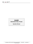
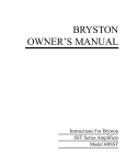
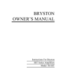
BRYSTON
OWNER’S MANUAL
Instructions For Bryston
SST Series Amplifiers
Model 14B SST
14B SST Series Amplifier
Table of Contents
General Introduction
Description
Installation and Ventilation
Page 1
Rear Panel Input Settings/Connections
Setting Input Selector Switch
Balance Input Connector Configuration
Setting Input Sensitivity
Page 2
Output Binding Posts
Page 3
Front Panel Description
LED Indicator (Power-up Sequence)
LED Indicator (Operating Conditions)
Page 4
Power Control Panel
Master Circuit -Breaker
AC Power Input
Local/Auto Switch
Local/External Switch
Page 5
Block Diagrams
Page 6
Typical Performance Graphs
Page 7-10
Technical Specifications
Page 11
Important Warranty Information
Back Cover
14B SST Series Amplifier
Introduction
Thank you for choosing the 14B SST SERIES Stereo Power Amplifier.
Bryston welcomes any suggestions you may have, or comments regarding the operation of your amplifier. We consider
you, our customer, to be Bryston’s most important resource, and your opinion is very much appreciated.
Description 14B SST
The 14B SST is a dual channel 600 Watt audio power amplifier. The 14B SST selects a balanced or single ended input
and a gain of 29dB (UNBAL or BAL+6db) or 23dB (BAL REG) may be selected. The 14B SST includes ‘soft start’ power
control circuitry to eliminate high inrush currents when A/C power is applied. The power up or turn-on of the 14B SST may
be activated by a remote control voltage 4v to 12v ac or dc.
Warranty ( see back page for details )
Shipping Box & Packing Material
Please keep the original shipping box and all packing material. This will ensure the amplifier is protected in future transport. In the unlikely event you have a problem and must return it for service you must use the proper packing material.
Ship the amplifier only in the original packing material, as the unit is not insurable by carriers otherwise.
Installation ( see rack mounting section if applicable )
Ventilation. The most important installation consideration is ventilation. The 14B SST amplifier is convection cooled.
Unrestricted air-flow across the 14B SST heat sinks is a must. For this reason do not install anything directly above it. Allow
3.5’ (2u) to 5” (3u) inches of space above and to the sides of this amplifier. Do not install directly above other heat generating equipment. Should your instillation conditions be constricted, then additional forced air-cooling may be necessary.
Bryston can provide an optional fan package if required. Thermal shut down during operation indicates insufficient air flow,
and a remedy must be found for cooling the amplifier. Provide a minimum 6” space to the rear of the amplifier for ventilation and dressing cables to and from the amplifier.
Never operate the amplifier in a vertical position.
Wiring the SST amplifier ( also see rear panel description )
Speaker wires should be as short as practical. Use quality wire, and if runs are more than 3 meters use at least 12 gage
wire. The speaker binding posts will accept wire up to 3 gage in size. Bryston offers speaker cables and amp interconnects
for your application. Check our website under products/cables (www.bryston.ca) for more information.
A/C power
Before plugging in the power cord be sure your 14B SST amplifier is specified for the correct a/c voltage for your locality. The voltage is listed on the label found at the upper right of the rear panel. The circuit feeding the 14B SST should be
sufficient so as not to cause the circuit breaker to trip (15 amp min). Note: the 14B SST when delivering maximum power
into a 4 ohm load, will consume all the available power in a normal household circuit, therefore a dedicated electrical circuit may be necessary with this situation. Never lift the safety ground to the amplifier nor remove the ground pin from the
plug.
IMPORTANT NOTE: If your 14B SST is equipped with a 20 amp breaker, a dedicated line should be run with a minimum
of 12 gage wire. Please consult an authorized Electrician before installing this amplifier.
Bryston and/or it’s dealers will not be held responsible for and damage that may happen to person/property if the proper
procedures listed above are not taken.
Power line conditioners will not improve the 14B SST amplifier performance, in fact most of the time they restrict the
flow of current to the amplifier, reducing performance at higher output levels
1
14B SST Series Amplifier
Rear Panel Input / Output Connections
Fig 1
2
1/4” PHONE PLUG
1
4
3
XLR TYPE
RCA PLUG
5
1. Input Select Switch.
Each SST channel gives the user the option of switching between either balanced input or single ended input.
Input Sensitivity Selection.
The optimum gain setting will depend upon the source pre-amp operating level, and or personal preference.
The UNBAL setting is used when the source is single-ended, or from a transformer coupled balanced source.
The BAL+6 setting is used when the source output is actively balanced.
The UNBAL and BAL+6 setting provides the most amplifier gain -29 dB. (1v in = 100w @ 8 ohms.)
(noise -110 dB)
The BALsetting is used when the sources output is actively balanced.
This setting with any systems where the volume control rotation is limited to the bottom half of the
control or less.
The BAL setting provides an amplifier gain - 23 dB. ( 2v in = 100w @ 8 ohms.) ( noise -113 dB )
The noise is referenced in dB below rated output. Different input configurations result in slightly different noise readings.
The above noise ratings represent minimum readings, actual readings may be better.
2. Balanced Input connector. ( Imp. 20k )
This input connector accepts standard ‘XLR’ or 1/4” TRS .
Use quality, 100% shielded cables with gold plated connectors.
3. Single Ended Input. ( Un-balanced input ) ( Imp. 50k )
This input connector accepts standard ‘RCA’ or ‘Phono’ connectors.
Use quality, 100% shielded cables with gold plated connectors.
Balanced input Vs Single ended input:
The balanced input requires a balanced pre-amp source. Balanced systems provide noise rejection from external
electrical interference, so cable length can be very long ( 50m or longer ).
The single ended or unbalanced input is provided for pre-amps without balanced output. Single-ended cables should be
kept to 20’ (7m) or less. In general never use longer cables than necessary, never coil excess cable length, and keep
signal wires away from AC power or speaker cables.
4. Level Control. (pro models only)
The level control will attenuate the input signal level from 0dB through -14dB.
2
14B SST Series Amplifier
5. Output binding posts.
The RED binding post is the in-phase amplifier output. Connect to this post the (+) terminal on the loudspeaker.
The BLUE binding post is the inverted-phase amplifier output. Connect to this post the (-) terminal on the loudspeaker.
Note: At no time should either output be connected to a ground, or chassis. Failure of the amplifier may result.
Never connect either output in parallel with another amplifier.
The minimum recommended loudspeaker load is 4 ohms.
The Output binding posts provide three different interconnect options. Combinations may be used when bi-wiring. See figure 2 below. Cables should be kept as short as practical and should never be terminated with connectors that may become
confused for AC power connectors. Cables should be dressed away from input and power cables.
1. Banana plugs offer a quick disconnect option. Before inserting a banana plug into the binding post be sure to tighten the
post nut to avoid rattling and to provide full insertion of the banana plug. Gold plated locking banana plugs are available
from Bryston.
2. Spade lugs provide high contact area and secure fastening. Lugs should be gold plated. See diagram for details.
Post diameter is 5/16’ ( 8mm ), lug width 5/8” (16 mm). Gold plated spade lugs are available from Bryston.
3. Stripped bare wire up to 3 gage can be inserted through the hole in the binding post and held in place by tightening the
post knob. Additional tightening pressure can be achieved using a coin in the slots of the knob. Do not over tighten or the
binding post may become damaged. Note that copper wire is malleable and may require further tightening after the initial
installation.
Fig 2
2
3
Spade lug dimensions
5/8”
5/16”
1
Coin
3
14B SST Series Amplifier
2
1
Front Panel
1. 'SST POWER' switch
The front panel label 'SST POWER', is a touch sensitive membrane switch used to apply or remove a/c line power to the
soft start circuitry. Push firmly the center of the switch until the power-up sequence begins. Push again and the amplifier
will power-down. ( Note: the rear circuit breaker must be on for the amplifier to power-up)
2. LED Indicator
The 14B SST has an LED indicator to monitor the following conditions:
indicates the amplifier has no power.
UNLIT RED indicates the amplifier is muted (power-up)
GREEN indicates the amplifier operation is normal.
FLASHING RED - indicates the amplifier clipping.
ORANGE indicates channel thermal shutdown.
Power up sequence
After pushing the 'SST POWER' switch, the LED will turn from unlit to red (mute). When the power supply has stabilized
the amplifier will come out of mute and the LED will change to green (normal operation).
Unlit LED ( No power )
The 14B SST LED when unlit indicates no A/C mains power is present and the amplifier probably needs only to be powered on or the rear panel circuit breaker is switched off.
Clipping ( flashing red )
Clipping occurs when the channel output level no longer can follow the level increase at the input (Overdriven input condition). When the 14B SST is driven into clipping the LED will change from green to red then back to green when the
level is reduced ( Flashing Red ). Momentary clipping can be tolerated, however it indicates that maximum un-distorted
power has been surpassed and potential speaker damage may result if overload conditions persist. Any amplifier that is
constantly operated into clipping indicates a more powerful amplifier is needed for that application.
Thermal Shutdown ( orange )
The 14B SST has thermal shutdown circuitry to prevent damage due to overheating.
Should thermal shutdown occur, the amplifier will mute, and the LED will turn orange indicating this condition. When the
amplifier has cooled to a safe operating condition the 7B SST will return to normal operation.
Persistent Thermal shutdown indicates steps need to be taken to increase airflow across the heat sink. ( Also see installation section on ventilation ).
4
14B SST Series Amplifier
Power Control
1. Master circuit - breaker.
The 14B SST amplifier uses a magnetic-trip circuit breaker (1) to protect the amplifier.
This switch should be ‘OFF’ during installation. When switched ‘OFF’
all A/C power is removed from the amplifier, including standby power.
The circuit breaker is not the power switch and should be switched to and left ‘ON’ after
the installation is complete. Use the “SST POWER” switch or an external control voltage
to Power-up or Power-down the amplifier.
Should the breaker trip, lower or remove the amplifier input signal. Switch the breaker to
the ‘ON’ position. Then power the unit up normally.
The circuit breaker must be ‘ON’ at all times for the 14B SST amplifier to operate.
1
2
2. AC power input.
On the rear panel is provided a high current plug for the power cord receptacle. Check that the voltage rating on the label
conforms with your locality. With the circuit breaker ‘OFF’ insert the power cord into the 14B SST amplifier, then plug the
other end to an appropriate A/C power outlet.
3. Power-Up ( Local / Auto switch. )
A. In “Local” position either the front panel ‘SST POWER” switch or an
external voltage controls the power-up of the 14B SST amplifier.
B. “Auto” is used when the 14B SST amplifier is powered from a switched power
outlet.
The ‘SST POWER’ switch and / or control voltage will function normally
after the initial power up.
4
3
4. External control voltage power up ( Local / external switch.)
A. To power-up the SST amplifier using an external control voltage, supply a 4v to 12v A/C or DC control voltage to the
‘IN’ terminals of connector ( 5 ).
Use paired wire of 22 to 18 gage sufficient in length between the source device and the SST amplifier. (see ‘W’ ).
Select switch (4) to “External”. The amplifier will now power-up only when the control voltage is present (on).
Immediately following power up, the control voltage will appear at the ’OUT’ terminals of connector (5) for the control
of other equipment.The removal of the control voltage (0v) causes the amplifier to turn ‘off’ and the control voltage at
the ‘OUT’ terminals is interrupted.
B. In the“Local” setting of switch (4) the 14B SST amplifier will ignore the control voltage, and power up only by using
the front panel ‘SST POWER’ switch, or as in section 3 above. If a control voltage is present at the ‘IN’ terminals it
will still be available at the ‘OUT’ terminals after the power-up sequence.
Control Voltage source
4 to 12v ac or dc
fig W
Control voltage wire preparation
for screw terminals
separate 1”
18 to 22
gage
wire
to other voltage controlled devices
1/4”
strip
Bryston part number CO-110A-11104
Note:
The ‘OUT’ terminals are connected to the ‘IN’ terminals once the 14B SST amplifier has powered-up.
The control current is determined by the source equipment. The carrying current of the ‘OUT’ relay is 2 amps.
The 14B SST control circuitry itself draws less than 2 mA from the control current when operating.
5
14B SST Series Amplifier
6
14B SST Series Amplifier
Typical Band-pass Noise
Power supply artifacts are all below -95 dBu
BAL+6db input shown
dBu: dB relative to a reference of 0.7746 Volts
Typical THD+N Harmonic Content
The harmonic content of the 14B SST is all even order.
7
14B SST Series Amplifier
Typical Frequency Response 14BSST
8 ohm 600w
4 ohm 900w
Typical Phase Response
4 ohm 900w
8 ohm 600w
8
14B SST Series Amplifier
Typical THD+N Sweep
Graph shows that distortion is
essentially unaffected by load.
BAL+6db input shown.
4 ohm 900w
8 ohm 600w
Typical IMD Sweep
4 ohm 900w
8 ohm 600w
9
14B SST Series Amplifier
Damping Factor
8 ohm reference
10
14B SST Series Amplifier
Technical Specifications
Power Output
600 watts per channel into 8 ohms
900 watts per channel into 4 ohms
Gain Select and Sensitivity
29dB - 2.5Vin = 600W @ 8 Ohms - (Unbalanced position)
29dB - 2.5Vin = 600W @ 8 Ohms - (Balanced +6db position)
23dB - 5.0Vin = 600W @ 8 Ohms - (Balanced Reg position)
Input Impedance
50 Kohms single ended
20 Kohms balanced
Distortion IM or THD+noise
< 0.005% 20Hz to 20kHz at 600 watts into 8 W
< 0.007% 20Hz to 20kHz at 900 watts into 4 W
Noise Measured with input shorted - 20Hz to 20kHz.
>110dB below rated output 29dB gain (- 75dBu)
>113dB below rated output 23dB gain (- 78dBu)
Slew Rate > 60 volts per microsecond
Power Bandwidth < 1 Hz to over 100 kHz
Damping Factor Over 300 at 20 Hz, ref. 8 ohms
Dimensions - L x H x D
19” version with handles
48.3 x 17.8 x 49cm - 19” x 7” x 19.3“
mounted rack depth - 42.5cm - 16.7"
17” version
43.2 x 17.8 x 44cm - 17” x 7” x 17.2“
Weight: approx. 36.4kg - 80 lbs
Power Consumption & Heat Load
At Idle Max. Heat Dissipation -
215 Watts
733 Btu/Hr.
Output @ 600W @ 8 ohms Max. Heat Dissipation 8 ohms -
1284 Watts
2333 Btu/Hr.
Output @ 900W @ 4 ohms Max. Heat Dissipation 4 ohms -
1980 Watts
3684 Btu/Hr.
11
BRYSTON 20 -YEAR WARRANTY
Bryston products are warranted to be free from
manufacturing defects for a minimum of twenty
years from the original date of manufacture. This
includes parts, labour and return shipping to the
first owner and all subsequent owners. Warranty
coverage is automatic and commences with the
original date of manufacture which is kept on file
at Bryston.
In the event of a defect or malfunction, Bryston
will remedy the problem by repair or replacement,
as we deem necessary, to restore the product to
full performance.
This warranty is considered void if the defect,
malfunction or failure of the product or any component part was caused by damage ( not resulting
from a defect or malfunction ) or abuse while in
the possession of the customer. Tampering by
persons other than factory authorized service
personnel, or failure to fully comply with Bryston
operating instructions, voids the warranty.
This warranty gives you specific legal rights and
you may also have other rights which may vary
from province to province and country to country.
BRYSTON SERVICE CANADA:
24 STEINWAY BLVD., UNIT 48
ETOBICOKE, ONTARIO
CANADA M9W 6T8
PHONE: 416-675-2585
FAX: 416-675-3103
BRYSTON LTD.
P.O. BOX 2170
677 NEAL DRIVE
PETERBOROUGH, ONTARIO
CANADA
K9J 7Y4
BRYSTON SERVICE U.S.A.:
70 COVENTRY ST.
SUITE #5
NEWPORT VERMONT.
U.S.A. 05855
PHONE: 802- 334-1201
FAX: 802-334-6658
FOR BRYSTON SERVICE OUTSIDE CANADA:
CONTACT YOUR LOCAL DISTRIBUTOR
OR
CHECK OUR WEB SITE AT: [email protected]
OR
CALL BRYSTON DIRECTLY AT:
PHONE: 705-742-5325
FAX: 705-742-0882