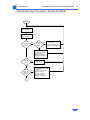
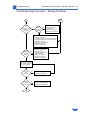
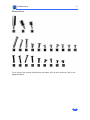
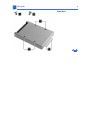
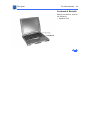
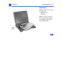
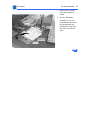
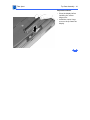
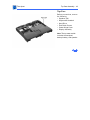
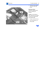
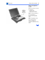
1
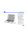
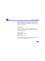
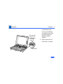
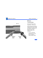
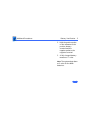
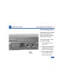
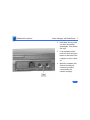
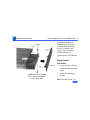
K Service Source
PowerBook 1400
PowerBook 1400c/117, /133, /166,
PowerBook 1400cs/117, /133, /166
K Service Source
Hot Issues
PowerBook 1400 Series
Hot Issues
Overview - 1
Overview
This chapter is designed to highlight unique or highpriority product issues that you should be aware of before
servicing the PowerBook 1400.
This chapter alerts you to important issues and provides
links to other areas in the manual where more complete
information can be found. This chapter is not intended to
replace other parts of this manual; it merely provides a
pointer to pertinent information in those chapters.
The date the Hot Issue was published is indicated in
parentheses after the title.
Hot Issues
Bottom Case Latch Replacement (2/98) - 2
Bottom Case Latch Replacement (2/98)
Issue: The latches on the bottom case battery and media bays
may come off. The latches are replaceable. Please replace
the latches for customers rather than replacing the entire
Bottom Case Assembly.
Parts Identification: Order Replacement Part 922-3304:
Latch, Bottom Case, PB 1400. The latches come in a package
of five.
Replacement Procedure: For detailed instructions, see
“Bottom Case Latch Replacement” in the Additional
Procedures chapter of this manual.
Hot Issues
Logic Board Identification (2/98) - 3
Logic Board Identification (2/98)
Issue: There are two logic boards with ROM version 3 that
could be used in the PowerBook 1400, 117MHz and the
PowerBook 1400, 133 MHz units. Because dealers must
return the same part they ordered to receive
reimbursement, it is important to properly identify the
logic board before ordering a replacement.
Part Number 661-1188 has ROM U3 (Low, 341S0203)
and ROM U4 (High, 341S0204). It works in PowerBook
1400, 117 MHz and 133 MHz units.
Part number 661-1381 has ROM U3 (Low, 341S0364)
and ROM U4 (High, 341S0365). It works in PowerBook
1400, 117 MHz, 133 MHz, and 166 MHz units.
You may receive a 661-1381 logic board as a replacement
for a 661-1188 if that is the board currently in service
Hot Issues
Logic Board Identification (2/98) - 4
stock. Since it will work in all the PowerBook 1400 units,
this should not pose a problem to customers or Service
Providers.
Parts Identification: To check the ROMs on the PowerBook
1400, 117 MHz units, remove the factory-installed
Memory Expansion Card (the card closest to the
Microprocessor Daughterboard).
To check the ROMs on the PowerBook 1400, 133 MHz units,
remove both the factory-installed Memory Expansion Card
and the Microprocessor Unit Daughterboard.
For instructions on removing any of these parts, see the
Take Apart chapter of the PowerBook 1400 manual.
Hot Issues
Door Replacement for PowerBook 1400 CD-ROM Drives (12/
Door Replacement for PowerBook
1400 CD-ROM Drives (12/97)
Issue: The doors of the CD-ROM drives used with the
PowerBook 1400 media bay may break at the tabs used to
attach it to the drive mechanisms tray. These doors are
replaceable. Please replace the door for customers rather
than replacing the entire CD-ROM assembly.
Solution: For more information on parts identification and
replacement procedures, see “Door Replacement for CDROM Drives” in the Additional Procedures chapter of this
manual.
Hot Issues
1 GB Hard Drives Formatted Improperly (2/97) - 6
1 GB Hard Drives Formatted
Improperly (2/97)
Issue: PowerBook 1400 computers that shipped with one
gigabyte (1 GB) hard drives were formatted improperly.
The improper formatting caused 1 GB hard drives to appear
to have only 750 MB of total disk space.
Solution: This formatting issue has been noted and corrected
at Apple's manufacturing site. This issue should no longer be
a factor in any new PowerBook 1400 computers. Follow the
steps below for identifying models of the PowerBook 1400
that shipped with 1 GB drives, determining whether these
drives were formatted improperly, and reformatting the
hard drives.
Hot Issues
1 GB Hard Drives Formatted Improperly (2/97) - 7
Which models shipped with a 1 GB hard drive?
Not all PowerBook 1400 computers shipped with 1 GB hard
drives. Only the following models shipped with 1 GB hard
drives.
• M4856 Macintosh PowerBook 1400c/117
• M5576 Macintosh PowerBook 1400c/133
How can I tell if the 1 GB hard drive is formatted improperly?
If you aren't sure whether or not the hard drive has been
improperly formatted, do the following:
1
Open the hard drive window.
3
Select "by icon" from the menu.
2
4
Pull down the View menu.
Add up the numbers for "in Disk" and "available". If
these numbers add up to approximately 750 MB, then
Hot Issues
1 GB Hard Drives Formatted Improperly (2/97) - 8
the drive will need to be reformatted to obtain the full
size of 1 GB.
How do I reformat the hard drive?
If the PowerBook computer has an improperly formatted
hard drive, follow the steps below to reformat the drive.
Important: Reformatting the hard drive will cause all the
data files on the drive to be permanently erased. Be sure to
save important files to other media before reformatting.
1
2
Back up the important data from the hard drive to
another hard drive or to floppy disks. All of the software
that came with the computer is contained on the CD that
came with it, so you only need to back up files created by
the customer.
Start up from the PowerBook System CD.
Hot Issues
1 GB Hard Drives Formatted Improperly (2/97) - 9
3
Run Drive Setup to reformat/initialize the hard drive.
5
Restart the PowerBook and check the hard drive window.
The amount of space "in disk" and "available" should total
1 GB.
4
Restore all the software from the PowerBook 1400 CD.
Hot Issues
Missing HD Reference File (2/97) - 10
Missing HD Reference File (2/97)
Issue: A reference file needed by the system was not
installed on the PowerBook 1400’s hard drive during the
manufacturing process. As a result, if customers use a Disk
Utility program (such as Apple’s Disk First Aid) that
addresses this reference file, they will receive an error
message. For example, customers using Disk First Aid to
verify their hard drive will see the error message, “This is
not an HFS disk.”
The absense of this file does not compromise data integrity
in any way and the error messages do not necessarily
indicate that the customer is experiencing a problem with
their PowerBook 1400. It only affects disk utility programs
that attempt to address this reference file and it is easily
corrected.
Hot Issues
Missing HD Reference File (2/97) - 11
Solution: The “PowerBook 1400 HD Updater” corrects this
problem. A Read Me file included with the updater provides
customers with step-by-step instructions for installing the
updater and explains why they need it.
Customers with access to the internet will find two files—
“PB 1400 HD Updater 1.0” (the Read Me file) and “PB
1400 HD Updater 1.0.sea,” using the following path:
Apple SW Updates/US/Macintosh/PowerBook/PB 1400/
PB 1400 HD Updater 1.0/PB 1400 HD Updater 1.0.sea
Service Providers or customers can also order the PB 1400
Updater on a floppy disk by calling 1-888-243-0008.
Hot Issues
PowerBook 1400: Video-Out Upgrade Kit Ships with Wrong
PowerBook 1400: Video-Out Upgrade
Kit Ships with Wrong Screws (2/97)
Issue: Some of the initial Macintosh PowerBook 1400 8-bit
Video-Out Upgrade Kits (M4509LL/A) shipped with the
wrong screws. Instead of two (2) short Phillips-head
screws, the product was packaged with one (1) long and one
(1) short torx-8 screws.
Solution: This packaging error has been corrected, and
future shipments of the product will contain the correct
screws. To assist customers who received the wrong screws,
Apple has made the correct ones available via Support
Related Fulfillment, as follows:
Part Number
LGX-0098
Description
Screw Kit
K Service Source
Basics
PowerBook 1400 Series
Basics
Product Overview - 1
Product Overview
The PowerBook 1400 Series
is the first PowerBook to
support fully modular
features. Customers can
upgrade their floppy drive,
CD-ROM drive, and
expansion memory.
Customers can also replace
the removable panel on the
top of the case with a clear
or colored panel that came
with the system.
CD-ROM Drive
or
Floppy Drive
The PowerBook 1400 Series
features a PowerPC 603e
RISC microprocessor
Basics
Product Overview - 2
running at 117, 133, or 166 MHz; built-in PC Card
technology; and infrared communication. Also offered are
two PowerBook displays: a dual-scan passive matrix
(FSTN) or an active matrix (CTFT).
Basics
System Configurations - 3
System Configurations
The PowerBook 1400 Series computers come in the
following configurations:
PowerBook 1400cs (October ‘96)
•
•
•
•
•
Processor: 117 MHz PowerPC 603e
RAM/Hard drive: 12 MB/750 MB or 16 MB/750 MB/CD
Display: 11.3" dual-scan passive matrix (FSTN)
Battery: 2-4-hour NiMH
Weight: 6.7 lb. with floppy drive; slightly more with
CD-ROM drive
Basics
System Configurations - 4
PowerBook 1400c (October ‘96)
•
•
•
•
•
Processor: 117 MHz PowerPC 603e
RAM/Hard drive: 16 MB/1 GB/CD
Display: 11.3" active matrix (CTFT)
Battery: 2-4-hour NiMH
Weight: 6.6 lb. with floppy drive; slightly more with
CD-ROM drive
PowerBook 1400c/133 (February ‘97)
• Processor: 133 MHz PowerPC 603e with 256 KB L2
cache
• RAM/Hard drive: 16 MB/1 GB/CD or 16 MB/1.3 GB/CD
• Display: 11.3" active matrix (CTFT)
• Battery: 2-4-hour NiMH
• Weight: 6.6 lb. with floppy drive; slightly more with
CD-ROM drive
Basics
System Configurations - 5
PowerBook 1400cs/133 (April ‘97)
• Processor: 133 MHz PowerPC 603e with 256 KB L2
cache
• RAM/Hard drive: 12 MB/1 GB or 16 MB/1.3 GB/CD
• Display: 11.3" dual-scan matrix (FSTN)
• Battery: 2-4-hour NiMH
• Weight: 6.7 lb. with floppy drive; slightly more with
CD-ROM drive
PowerBook 1400c/166 (June ‘97)
• Processor: 166 MHz PowerPC 603e with 256 KB L2
cache
• RAM/Hard drive: 16 MB/2 GB/CD
• Display: 11.3" active matrix (CTFT)
• Battery: 2-4-hour NiMH
• Weight: 6.6 lb. with floppy drive; slightly more with
CD-ROM drive
Basics
System Configurations - 6
PowerBook 1400cs/166 (November ‘97)
• Processor: 166 MHz PowerPC 603e with 256 KB L2
cache
• RAM/Hard drive: 16 MB/2 GB/CD
• Display: 11.3" active matrix (CTFT)
• Battery: 2-4-hour NiMH
• Weight: 6.6 lb. with floppy drive; slightly more with
CD-ROM drive
Basics
Repair Strategy - 7
Repair Strategy
Service the PowerBook 1400 Series computers through
module exchange and parts replacement. Customers can
request on-site service from an Apple Authorized Service
Provider Plus (AASP+) Apple Assurance (US only), or
request a courier through the Apple Canada Technical
Answerline (Canada only). They can also choose carry-in
service from an AASP.
Ordering
Apple Service Providers planning to support the computer
systems covered in this manual may purchase Service
modules and parts to develop servicing capability. To order
parts, use the AppleOrder (US only) or ARIS (Canada only)
system and refer to “Service Price Pages.”
Basics
Repair Strategy - 8
Large businesses, universities, and K-12 accounts must
provide a purchase order on all transactions, including
orders placed through the AppleOrder (US only) or ARIS
(Canada only) system.
USA Ordering
US Service Providers not enrolled in AppleOrder may fax
their orders to Service Provider Support (512-9088125) or mail them to
Apple Computer, Inc.
Service Provider Support
MS 212-SPS
Austin, TX 78714-9125
For US inquiries, please call Service Provider Support at
800-919-2775 and select option #1.
Basics
Repair Strategy - 9
Canadian Ordering
Canadian Service Providers not enrolled in ARIS may fax
their orders to Service Provider Support in Canada
(1-800-903-5284). For Canadian inquiries, please call
Service Provider Support at 905-513-5782 and select
option #3.
Basics
Warranty/AppleCare/ARIS - 10
Warranty/AppleCare/ARIS
US Only
The PowerBook 1400 Series computers are covered under
the Apple One-Year Limited Warranty. The AppleCare
Service Plan is also available for these products. Service
Providers are reimbursed for warranty and AppleCare
repairs made to these computers. For pricing information,
refer to “Service Price Pages.”
Canada Only
The PowerBook 1400 Series computers are covered under
first-year AppleCare. The Extended AppleCare Service Plan
is also available for these products. Service Providers are
reimbursed for first-year warranty and Extended
AppleCare repairs made to these computers. For pricing
information, refer to “Service Price Pages.”
Basics
Front View - 11
Front View
Sleep
Indicator
Brightness
Control
Contrast
Control
Microphone
Battery
CD-ROM Drive
or
Floppy Drive
The front of the computer
includes the battery, floppy
drive or CD-ROM drive,
microphone, contrast
control, brightness control,
and sleep indicator.
Basics
Side View - 12
Side View
The left side panel contains
two PC Card (PCMCIA card)
slots and PC Card eject
buttons.
PC Card
Eject Buttons
Two PC Card
(PCMCIA Card) Slots
Basics
Rear Panel - 13
Rear Panel
The rear panel contains the
I/O ports, reset button,
infrared window, and
security slot.
Sound
Output Port
Power
Adapter Port
Sound
Input Port
Expansion Port
Security
Slot
SCSI Port
(HDI-30)
Apple Desktop
Bus (ADB) Port
Reset
Button
Infrared
Window
Printer/External
Modem Port
Basics
Logic Board - 14
Logic Board
Speaker
Display
Microprocessor
DaughterInverter
Board
Keyboard
Hard
Drive
PCMCIA
Trackpad
Factory
RAM Customer
RAM
Video
CD-ROM
Drive
Floppy
Drive
The logic board contains the
daughterboard and optional
factory-installed and
customer-installed memory
expansion cards. It also
contains numerous
connectors.
Basics
Cable Matrix - 15
Cable Matrix
For a matrix of cables that work with specific models of the
PowerBook family of computers, select the PowerBook Cable
Matrix located in Hardware/Compatibility Charts.
Basics
Battery Information - 16
Battery Information
Warning: Use only the battery supplied with the PowerBook
1400 Series or an identical model. Batteries designed for
other portable computers may look similar, but they may
not work with your computer and may damage it.
Battery Matrix
For a matrix of batteries that work with specific models of
the PowerBook family of computers, select the PowerBook
Battery Matrix located in Hardware/Compatibility Charts.
Basics
Battery Information - 17
Nickel-Metal-Hydride
Batteries
The PowerBook 1400 Series
computers use nickelmetal-hydride (NiMH)
batteries. Each battery
provides power for up to
four hours of work time,
depending on the system
configuration and battery
conservation features
employed.
Basics
Battery Information - 18
Battery Handling Guidelines
The following are guidelines for properly handling the
PowerBook 1400 Series batteries:
Warning: NiMH batteries contain hazardous chemicals. Send
undamaged, dead batteries to Apple for recycling—do not
discard dead batteries with other waste. If battery is
damaged, do not return it to Apple. Dispose of damaged
batteries according to local ordinances. Review battery
handling and disposal instructions in Safety Information in
Bulletins/Safety.
• Handle the battery carefully. Do not drop, puncture,
mutilate, or burn it.
• Do not leave a battery in the computer for longer than a
week without plugging in the power adapter.
Basics
Battery Information - 19
• Always put the battery cap on the battery when the
battery is out of the PowerBook. The battery contacts
should not be exposed when the battery is out of the
computer.
• Do not leave the battery in hot locations (such as the
trunk of a car).
• Do not store a battery for longer than six months without
recharging it.
• Recharge batteries only as described in the user’s manual
and only in ventilated areas.
Basics
PC Card Handling - 20
PC Card Handling
Two PC Card slots (also
known as PCMCIA slots) are
featured in the PowerBook
1400 Series. The two slots
accept a variety of thirdparty PC Cards with 68-pin
connectors.
There are three types of PC
Cards: Type I (3.3 mm),
Type II (5 mm), and Type III
(10.5 mm). Type I and Type
II cards fit in either the
upper or lower slot of the PC
Card unit. Type III cards can
only be placed in the lower
Basics
PC Card Handling - 21
slot. When a Type III card is in the lower slot, the upper slot
cannot be used.
The following are guidelines for properly handling PC Cards:
• Use only cards that are compatible with the PC Card unit.
Refer to the compatibility information that came with the
card. If you cannot find the compatibility information,
call the card vendor.
• Use an SRAM card for extra storage only. If this type of
PC Card is used to start up the computer, an error
message will be received.
• Do not insert anything other than a PC Card into the card
slots.
• The computer must be on or off in order to eject a PC
Card. When the computer is in sleep mode, a PC Card
cannot be ejected.
Basics
PC Card Handling - 22
• Before you eject a card, make sure nothing is blocking
the card’s slot.
• If you want to use the card again immediately, pull it out
about an inch more and then push it back in. If you don’t
follow this procedure and try to push the card back in to
use it again, the card will not engage properly.
• Do not pull on a PC Card before it has been ejected out of
the slot. Forcing a PC Card out of the slot may damage the
computer or the card.
K Service Source
Specifications
PowerBook 1400 Series
Specifications
Introduction - 1
Introduction
You can also find specifications information for this product in the
Spec Database, which you can access in one of three ways:
— Launch it directly by double-clicking the Apple Spec Database
runtime alias at the top level of the Main Service Source CD.
— Select "Apple Spec Database" from the Service Source dropdown main menu.
— Click the Acrobat toolbar icon for the database, which is near
the right end of the toolbar with the letters "SP."
Specifications
Processor - 2
Processor
CPU
Cache
PowerPC 603e microprocessor running at 117 MHz
PowerPC 603e microprocessor running at 133 MHz
PowerPC 603e microprocessor running at 166 MHz
256 KB second-level (L2) cache
Specifications
Memory - 3
Memory
RAM
12 or 16 MB of low-power DRAM
Customer-upgradeable
Expandable to 64 MB using TSOP low-profile RAM chips rated at
70 ns access time or faster
ROM
4 MB ROM
VRAM
1 MB VRAM
Specifications
Disk Storage - 4
Disk Storage
Floppy Drive
Removable 1.44 MB floppy drive (in the expansion bay or packed
separately if a CD-ROM drive is installed in the expansion
bay). Reads and writes Macintosh 1.4 MB floppy disks and
Windows, DOS, and OS/2 720K and 1.44 MB floppy disks;
reads Macintosh 800K disks
Hard Drives
750 MB, 1 GB, 1.3 GB, or 2 GB 2.5" hard drive
CD-ROM Drive
Removable 6x-speed, 8x-speed, or 12x-speed CD-ROM drive (in
the expansion bay, if included)
Specifications
I/O Interfaces - 5
I/O Interfaces
SCSI
PC Cards
ADB
SCSI port (HDI-30 connector) for hard drives, CD-ROM drives,
scanners, printers, and other devices; also supports
PowerBook SCSI disk mode
Two PC Card (PCMCIA card) slots support either two Type I or
Type II cards or one Type III card
Apple Desktop Bus (ADB) port for keyboard, mouse, or other
input devices using a low-speed, synchronous serial bus
200 mA maximum current draw for all ADB devices
Supports up to three ADB devices in a daisy chain (provided the
maximum current draw does not exceed the 200 mA limit)
Specifications
Serial
Sound
I/O Interfaces - 6
Serial port for printers, modems, LocalTalk network, or other
serial devices (RS-422)
Sound output port for external audio amplifier/powered speakers,
stereo mini-jack, 3-connector, standard 3.5 mm stereo
miniplug; sound input port for stereo sound input (line level),
stereo mini-jack, 3-connector, standard 3.5 mm stereo
miniplug
16-bit stereo sound in and out supports 44.1 kHz, 22 kHz, and 11
kHz sample rates
Infrared
Built-in infrared send and receive unit
Power Adapter
Power adapter port
Specifications
Security
I/O Interfaces - 7
Users may attach a security device such as the Kensington
Security Connector.
Specifications
Expansion Interfaces - 8
Expansion Interfaces
Expansion Slots
Expansion Bay
Expansion slot for optional user-installable card adds a connector
that can provide a video port, an Ethernet network connection,
or another device
Expansion slot for user-installable RAM expansion card. (Card
has connectors for optional second card plug-in.)
Expansion bay accepts a removable expansion bay module (floppy
drive, CD-ROM drive, stored NiMH battery, or other modules)
Specifications
I/O Devices - 9
I/O Devices
Keyboard
Built-in keyboard with 12 function keys
76 keys domestic, 77 keys ISO
3.0 mm travel keyboard
19 mm vertical and horizontal pitch
Trackpad
Integrated, solid-state trackpad
Microphone
Internal, electret, omnidirectional microphone
Specifications
Video - 10
Video
Macintosh
PowerBook 1400cs
Video Display
Macintosh
PowerBook 1400c
Video Display
11.3" diagonal, 800 x 600 dual-scan passive matrix (FSTN);
thousands of colors
11.3" diagonal, 800 x 600 active matrix (CTFT); thousands of
colors
Specifications
Electrical - 11
Electrical
Main Battery
Power Adapter
Backup Battery
Rechargeable nickel-metal-hydride (NiMH) battery
2-4 hours of use before recharging
Recharge time: slightly more than 2 hours
100-240 VAC line voltage
45 W, 50-60 Hz
50 milliamp-hour rechargeable battery for calendar/clock
maintenance. Also backs up contents of RAM for a few minutes
while battery is changed (when PowerBook is in sleep mode)
Specifications
Physical - 12
Physical
Dimensions
Weight
Height: 2.0 in. (54 mm)
Width: 11.5 in. (292 mm)
Depth: 9.0 in. (229 mm)
6.6 lb. (3.0 kg) with floppy drive expansion module
If the floppy drive is replaced with a CD-ROM drive, add .14 kg
(0.3 lb.) to the computer’s weight
Specifications
Environmental - 13
Environmental
Operating
Temperature
41° to 95° F (5° to 35° C)
Storage
Temperature
14° to 140° F (-10° to 60° C) Nickel-metal-hydride
-13° to 140° F (-25° to 60° C)
Relative Humidity
20% to 80% noncondensing
Operating Altitude
10,000 ft. (3,048 m) maximum
Shipping/NonOperating Altitude
15,000 ft. (4,572 m) maximum
K Service Source
Troubleshooting
PowerBook 1400 Series
Troubleshooting
General - 1
General
In each product manual on Service Source, you will find
Flowcharts and/or Symptom Charts designed to help you
diagnose and repair Apple computers.
If you have narrowed the problem down to a particular
symptom, start with the Symptom Charts. Because cures are
listed in the order of most likely solution, try the first cure
first. Verify whether or not the product continues to exhibit
the symptom. If the symptom persists, try the next cure.
If you are not sure what the problem is, or if the Symptom
Charts do not resolve the problem, refer to the Flowcharts.
If you require additional assistance, contact Apple Technical
Support. Refer to the About topic under the Do menu for the
Apple Technical Support phone number.
Troubleshooting
Symptom Charts/Startup - 2
Symptom Charts
Startup
RAM failure occurs
(eight-tone error
chord sequence sounds
after startup chord)
1
2
3
4
Remove RAM card (if present) and restart computer. If
startup sequence is normal, replace RAM card and retest.
Reseat RAM card and check connection.
Replace RAM card.
Replace logic board.
Troubleshooting
Hardware failure
occurs (four-tone
error chord sequence
sounds after startup
chord)
Symptom Charts/Startup - 3
1
2
3
4
5
6
Startup failure
occurs when using
minimum System
Folder and System
7.5.2.
Reset PRAM. (See Power Manager and PRAM Reset in
Additional Procedures.)
Remove floppy drive from media bay and restart computer. If
startup sequence is normal, insert floppy drive and retest.
Replace floppy mechanism.
Disconnect hard drive cable from hard drive and restart
computer. If startup sequence is normal, reconnect cable and
retest.
Replace hard drive.
Replace logic board.
Upgrade to System Enabler 1.2.1 or later. Refer to Apple Software
Updates on Service Source Companion CD.
Troubleshooting
Symptom Charts/Power - 4
Power
Note: You will hear only the click of the power-on button when
you attempt to start up a computer that lacks sufficient power to
start.
Computer won’t
power up
1
2
3
4
5
If sleep LED is continually on, backup battery power has been
interrupted. Restart computer by holding down reset actuator
10-20 seconds. If computer doesn’t restart, repeat 3–4
times.
Try known-good power adapter.
Try known-good, charged battery. (See Battery Verification
in Additional Procedures.)
Connect power adapter and restart computer in 3–4 minutes.
Replace logic board.
Troubleshooting
Screen is blank;
computer doesn't
respond
Symptom Charts/Power - 5
1
If sleep LED is continually on, backup battery power has been
interrupted. Restart computer by holding down reset actuator
10-20 seconds. If computer doesn’t restart, repeat 3–4
times.
2 Restart computer.
3 Disconnect power adapter, remove main battery, and restart
computer in 3-4 minutes.
4 Check power adapter cable.
5 Try known–good, charged battery. (See Battery Verification
in Additional Procedures.)
6 Try known-good power adapter.
7 Reset power manager. (See Power Manager and PRAM Reset
in Additional Procedures.)
8 Check all logic board cables and connections.
9 Replace keyboard.
10 Replace logic board.
Troubleshooting
Symptom Charts/Power - 6
After you remove
battery, some Control
Panel settings are
different
1
2
3
Check keyboard and backup battery cables and connections.
Replace backup battery.
Replace logic board.
Computer runs when
plugged into wall
outlet but not on
battery power;
battery voltage is
within tolerance
1
Reset power manager. (See Power Manager and PRAM Reset
in Additional Procedures.)
Reseat main battery to make sure battery is mating with
contacts on logic board.
Try known-good battery. (See Battery Verification in
Additional Procedures.)
Try known-good power adapter.
Replace logic board.
2
3
4
5
Troubleshooting
Symptom Charts/Power - 7
Power adapter is
plugged in, but
Control Strip doesn’t
indicate adapter is
connected
1
2
3
Verify that power adapter is connected correctly.
Try known-good power adapter.
Replace logic board.
When Shutdown is
selected with power
adapter plugged in,
computer shuts down
but immediately
powers back up
1
Reset PRAM. (See Power Manager and PRAM Reset in
Additional Procedures.)
Disconnect power adapter, remove main battery, disconnect
backup battery, and wait 15 minutes before retesting.
2
Troubleshooting
Low-power warning
appears
Symptom Charts/Power - 8
1
2
3
4
5
6
Attach power adapter and recharge battery.
Disconnect peripherals. If warning disappears when
peripherals are disconnected, verify that peripherals are
low-power.
Reduce use of floppy or hard drive, sound, backlight, or other
power-consuming devices, or reconnect power adapter.
Try known-good, charged battery. (See Battery Verification
in Additional Procedures.)
Try known-good power adapter.
Replace logic board.
Troubleshooting
Symptom Charts/Video - 9
Video
Note: A certain number of defects are inherent in display
technology and vary by many factors, including type of technology.
If you suspect that your display contains an abnormal number of
defects, call Apple Technical Support.
Partial or full row of
pixels is always on or
never comes on in an
active matrix display
1
2
3
Check display and backlight cables and connections.
Replace display.
Replace logic board.
Display is very light
or totally white
1
2
3
4
5
Adjust screen contrast and brightness settings.
Verify cable, inverter board, and logic board connections.
Replace inverter board.
Replace display.
Replace logic board.
Troubleshooting
Symptom Charts/Video - 10
Display stopped
working or dimmed
but is fine now
1
2
PowerBook 1400cs: If temperature is under 0° C or over
50° C, this reaction is normal. Let screen warm up for 30
minutes. If symptom persists, replace display.
PowerBook 1400c: Replace display.
Backlight doesn't
operate
1
2
3
4
5
6
7
Adjust screen contrast and brightness settings.
Verify that backlight cable connection is secure.
Check cable, inverter board, and logic board connections.
Verify that cables are not pinched or severed.
Replace inverter board.
Replace display.
Replace logic board.
No display, but
computer appears to
operate correctly
Note: If the sleep light is blinking and the computer is not in
sleep mode, reset the power manager.
Troubleshooting
Symptom Charts/Video - 11
1
2
3
4
5
6
7
Insert a disk into the floppy drive and press Command–E (to
eject a disk) to verify that computer is working.
Adjust screen contrast and brightness settings.
Verify display cable, inverter board, trackpad, keyboard, and
logic board connections.
Connect power adapter.
Replace inverter board.
Replace display.
Replace logic board.
Troubleshooting
Symptom Charts/Video - 12
Thin white line is
always on at middle of
screen
1
2
PowerBook 1400cs:Thin white line is normal.
PowerBook 1400c: Change the desktop pattern; if the line
remains, replace display.
An external monitor
connected to the
PowerBook shows no
video
1
Verify cable and cable connections between monitor and video
board.
Reseat video board and retest.
Replace video board.
2
3
Troubleshooting
An external monitor
connected to the
PowerBook shows
either horizontal or
vertical rolling, or
horizontal or vertical
distortion
Symptom Charts/Video - 13
1
2
Verify monitor using another computer.
Replace video board.
Troubleshooting
Symptom Charts/Sound - 14
Sound
No sound from
speaker
1
2
3
4
5
Verify that volume setting in Control Panel is above 0.
Verify that no external speaker is plugged in.
Verify speaker cable is seated on logic board.
Replace speaker.
Replace logic board.
Troubleshooting
Symptom Charts/Floppy Drive - 15
Floppy Drive
Note: The floppy drive cable referred to in this section is the
cable inside of the floppy drive case.
Audio and video
present, but floppy
drive in media bay
does not operate
1
2
3
4
5
Try known-good floppy disk.
Check floppy drive cable connection.
Replace floppy drive cable.
Replace floppy drive.
Replace logic board.
Troubleshooting
Disk ejects while
booting; display
shows Mac icon with
blinking X
Symptom Charts/Floppy Drive - 16
1
2
3
4
5
6
7
8
Try known-good system disk.
Verify that floppy disk is not locked.
Verify that trackpad and trackpad button are working.
Verify that keyboard is working.
Check floppy drive cable connection.
Replace floppy drive cable.
Replace floppy drive.
Replace logic board.
Troubleshooting
Disk does not eject
Symptom Charts/Floppy Drive - 17
1
3
4
5
6
Switch off system and hold trackpad button down while you
switch system on.
Eject disk manually by carefully inserting opened paper clip
into hole near floppy drive slot.
Check floppy drive cable connection.
Replace floppy drive cable.
Replace floppy drive.
Replace logic board.
1
2
3
4
5
Try known-good floppy disk.
Check floppy drive cable connection.
Replace floppy drive cable.
Replace floppy drive.
Replace logic board.
2
Disk initialization
fails
Troubleshooting
Read/write/copy
error
Symptom Charts/Floppy Drive - 18
1
2
3
4
5
6
Try known-good floppy disk.
Check floppy drive cable connection.
Try to format a floppy disk.
Replace floppy drive cable.
Replace floppy drive.
Replace logic board.
Troubleshooting
Symptom Charts/Hard Drive - 19
Hard Drive
Internal hard drive
does not spin up
1
2
3
4
5
6
7
Make sure power adapter is connected.
Disconnect external SCSI devices.
Check hard drive cable connection.
Use Hard Drive Format to reinitialize drive.
Replace hard drive.
Replace hard drive cable.
Replace logic board.
Troubleshooting
Symptom Charts/CD-ROM Drive - 20
CD-ROM Drive
CD-ROM drive does
not accept disc
1
2
3
Replace disc (if dirty or damaged).
Reinsert CD-ROM drive.
Replace CD-ROM drive.
Volume control does
not operate correctly
1
2
Check Control Panel Sound setting.
Reinsert CD-ROM drive.
Macintosh cannot
mount CD-ROM drive
1
2
Reinsert CD-ROM drive.
Replace CD-ROM drive.
Troubleshooting
Audio and video
present, but CD-ROM
drive in media bay
does not operate
Symptom Charts/CD-ROM Drive - 21
1
2
3
4
Try known-good CD-ROM disc.
Check CD-ROM drive cable connections (inside CD-ROM
case).
Replace CD-ROM drive cable.
Replace CD-ROM drive.
Troubleshooting
Symptom Charts/PC Card Module (PCMCIA) - 22
PC Card Module (PCMCIA)
PC Card won't eject
1
2
3
4
5
PC Card is inserted
but doesn't appear on
desktop
Note: Modem and communication cards may not appear on
desktop.
1
2
3
4
Make sure computer is not in sleep mode.
Make sure PC Card slot is not blocked.
Insert straightened paper clip into hole next to slot.
Verify that PC Card is not warped or damaged in any way.
Replace PCMCIA eject mechanism.
Try PC Card in the other slot.
Replace PC Card.
Replace PCMCIA eject mechanism.
Replace logic board.
Troubleshooting
Symptom Charts/PC Card Module (PCMCIA) - 23
Note: If “defective card” or “unrecognizable card” appears in
place of card name in PCMCIA Eject control panel, card is damaged
or computer does not have software required to support it. Eject
card.
System with PC card
performs poorly or
hangs during floppy
drive operations
Replace logic board.
Troubleshooting
Symptom Charts/Infrared Communication - 24
Infrared Communication
Infrared
communication is not
working
1
2
3
4
Clean infrared window with soft lint-free cloth.
Verify infrared board is properly seated.
Verify infrared signal is being received by host computer.
Replace PCMCIA eject mechanism
Troubleshooting
Symptom Charts/Peripherals - 25
Peripherals
After you connect
external SCSI device,
computer does not
boot
1
2
3
4
5
6
7
Verify that device and SCSI chain are terminated correctly.
Switch on external SCSI device before starting computer.
Check cable connections.
Try known-good SCSI cable.
Verify that SCSI ID select switch setting on external device is
unique.
Try known-good external SCSI device.
Replace logic board.
Troubleshooting
Cursor does not move
when you are using
trackpad
Symptom Charts/Peripherals - 26
1
2
3
4
5
6
Shut down computer, unplug adapter, and remove battery. Let
computer sit for 1 minute before restarting.
Reset power manager. (See Power Manager and PRAM Reset
in Additional Procedures.)
Check trackpad connections.
Check keyboard and logic board connections.
Connect low-power mouse and try to move cursor. If cursor
moves, try using trackpad and keyboard. If trackpad does not
move cursor, replace trackpad. If keyboard does not respond,
replace keyboard.
Replace logic board.
Troubleshooting
Cursor intermittently
does not move or
moves erratically
Symptom Charts/Peripherals - 27
Note: User must touch trackpad with the surface of only one
finger at a time and point directly down on the trackpad surface.
1
2
3
4
5
Clean trackpad surface (with computer off, using a nonstatic inducing material).
Check trackpad connections.
Replace trackpad.
Replace keyboard.
Replace logic board.
Troubleshooting
Cursor moves, but
clicking trackpad
button has no effect
Symptom Charts/Peripherals - 28
1
2
3
4
5
6
7
Reset power manager. (See Power Manager and PRAM Reset
in Additional Procedures.)
Check trackpad connections.
Check keyboard and logic board connections.
Replace trackpad.
Replace trackpad cable
Replace keyboard.
Replace logic board.
Troubleshooting
Cursor does not move
when you are using
mouse
Symptom Charts/Peripherals - 29
1
2
3
No response to any
key on keyboard
1
2
3
4
5
Check mouse connection to ADB port.
Try a known-good low-power mouse. If the known-good
mouse works, clean mouse ball and inside of original mouse
and retest. If the original mouse still doesn’t work, replace
it.
Replace logic board.
Verify that computer is on.
Reset the power manager. (See Power Manager and PRAM
Reset in Additional Procedures.)
Check keyboard connection by disconnecting and reconnecting
keyboard cables.
Replace keyboard.
Replace logic board.
Troubleshooting
Symptom Charts/Peripherals - 30
Known-good directconnect printer does
not print
1
Known-good network
printer does not print
1
2
3
4
5
6
2
3
4
5
Reset PRAM. (See Power Manager and PRAM Reset in
Additional Procedures.)
Verify that Chooser and Control Panel settings are correct.
Check cables.
Replace printer cable.
Try known-good printer.
Replace logic board.
Reset PRAM. (See Power Manager and PRAM Reset in
Additional Procedures.)
Verify that Chooser and Control Panel settings are correct.
Check cables.
Attach computer directly to printer, and retest.
Replace logic board.
Troubleshooting
I/O devices are
unrecognized, or
garbage is
transmitted or
received
Symptom Charts/Peripherals - 31
1
2
3
4
5
6
In disk mode,
computer does not
display SCSI icon
until host is booted,
or computer crashes
when host is shut
down
1
2
3
Reset PRAM. (See Power Manager and PRAM Reset in
Additional Procedures.)
Check cables.
Verify that SCSI device is correctly terminated.
Verify that SCSI select switch setting on external device is
unique.
Test device with known-good computer.
Replace logic board.
Verify that computer has a unique SCSI ID.
Check that SCSI disk mode cable is good and that connection is
tight.
Replace logic board.
Troubleshooting
Symptom Charts/Miscellaneous - 32
Miscellaneous
Sleep light won’t
come on
1
2
3
Verify that computer is in sleep mode and not powered off.
Reset power manager. (See Power Manager and PRAM Reset
in Additional Procedures.)
Replace inverter board.
Screen goes blank and
computer shuts down
every few minutes
Computer is going into system sleep to conserve battery power.
Adjust sleep delays in Control Panel or connect power adapter.
Application seems to
run slower after a few
seconds
Computer is switching to system rest. If system rest is
interfering with operation of application, connect power
adapter.
Hard drive is slow to
respond, or screen
goes blank too often
Adjust sleep delays in Control Panel or connect power adapter.
Troubleshooting
Troubleshooting Flowchart—Startup Problems - 33
Troubleshooting Flowchart—Startup Problems
START
Reset the
Power Manager.
Press power button to
begin boot sequence.
Do you
hear the
startup
tones?
No
Does any
video
appear?
No
1. Check the keyboard and
display cables.
2. Replace the keyboard.
3. Replace the logic board.
Yes
Yes
1. Check the volume.
2. Check the keyboard and
display cables.
3. Replace the speaker.
4. Replace the logic board.
Are the
startup tones
normal?
No
See "Startup" in the
Symptom Charts.
Yes
Does a
gray screen
appear with
pointer?
Yes
1
No
1. Check display/inverter cable
connections.
2. Replace the display and
backlight cables.
3. Replace the inverter.
4. Replace the display.
5. Replace the logic board.
Troubleshooting
Troubleshooting Flowchart—Startup Problems - 34
Troubleshooting Flowchart—Startup Problems
Go to
Start
1
Does
the
No
PowerBook continue
to boot to the
desktop?
Does
the flashing
question mark
appear?
No
1. Boot with extensions off.
2. Boot with Disk Tools
Update Driver.
3. Replace the hard drive.
4. Replace the logic board.
Yes
Yes
1. Reset PRAM.
2. Boot from Disk Tools.
3. If hard drive appears, reinstall system software.
4. If hard drive doesn't appear, see if Hard Drive
Format can reformat it.
5. Replace the hard drive cable.
6. Replace the hard drive.
7. Replace the logic board.
Do the
trackpad and
keyboard
function?
No
Yes
1. Reset PRAM.
2. Check the trackpad and
keyboard cables.
3. Replace the trackpad and
keyboard cables.
4. Replace the trackpad.
5. Replace the keyboard.
6. Replace the logic board.
Insert a known-good disk
into the floppy disk drive
and try to initialize it.
Does the
disk
initialize?
No
1. Replace the floppy drive cable.
2. Replace the floppy drive.
No
1. Reinsert the CD-ROM drive.
2. Replace the CD-ROM board.
3. Replace the CD-ROM drive.
Yes
Does the
CD-ROM
drive mount?
Yes
END
K Service Source
Take Apart
PowerBook 1400 Series
Take Apart
- 1
Screw Information
There are 16 types of screws in the PowerBook 1400. The
chart and information that follows will help you ensure that
the correct screws are used in putting the computer back
together.
Caution: To avoid stripping any screw heads, use a metric
phillips screwdriver when removing or installing phillips
screws.
Troubleshooting
- 2
Pictured Screws
For a visual of the screws (identified by the letters A-W) in their locations, refer to the
pages that follow.
Take Apart
- 3
Keyboard & Heatsink
Take Apart
- 4
Hard Drive
Take Apart
- 5
Top Case
Take Apart
- 6
Trackpad
Take Apart
- 7
Backup Battery
Take Apart
- 8
Speaker
Take Apart
- 9
CD-ROM Drive Assembly
Take Apart
- 10
Floppy Drive Assembly
Take Apart
- 11
Microprocessor
Daughterboard
Take Apart
- 12
Feet
Take Apart
- 13
Logic Board
Take Apart
- 14
PCMCIA Eject
Mechanism
Take Apart
- 15
Display Assembly
Take Apart
- 16
Bezel
Take Apart
- 17
Display
Take Apart
- 18
Clutch Assembly
Take Apart
- 19
Tools
Use the following tools for taking apart computers in the
PowerBook 1400 Series:
• #0 metric phillips screwdriver
• #00 metric phillips screwdriver
• 5 mm or 3/16" nut driver (for microprocessor
daughterboard standoffs)
• Small, flat-blade screwdriver (for ziff connectors and
general use)
• Dental pick (for trackpad cable connector and ferrite
bead)
• Swizzle stick (for name plate)
• Needlenose pliers (for I/O door hinge)
• Logic board separator (for PCMCIA eject mechanism)
Take Apart
Modules You Must Remove - 2 0
Modules You
Must Remove
Before you begin any takeapart procedure, you must
disconnect or remove these
modules:
• Power Adapter
• Battery
• Media Bay Device (CDROM Drive, Floppy
Drive, or Stored Battery)
Exception: You do not need
to remove these modules
when replacing the panel.
.
Take Apart
Modules You Must Remove - 2 1
1
Disconnect the power
adapter from the I/O
port.
Take Apart
Modules You Must Remove - 2 2
2
Slide the battery latch
over.
3
While holding the latch
open, pull the battery
out of its compartment.
Caution: When removing a
CD-ROM drive from the
media bay, push the latch on
the drive completely to the
right. Failure to do so may
damage the door.
4
Perform the same
procedure for removing
the device in the media
bay (CD-ROM drive,
floppy drive, or stored
Take Apart
Modules You Must Remove - 2 3
battery).
Replacement Caution: Always install the battery before
connecting the power adapter.
Take Apart
Top Case Assembly - 2 4
Top Case Assembly
The following parts are located in the top case assembly of
the PowerBook 1400 Series.
Take Apart
Top Case Assembly - 2 5
Speaker Grill
No additional removals are
necessary before continuing.
Take Apart
Top Case Assembly - 2 6
1
Firmly slide the grill to
the left and lift it off.
Take Apart
Top Case Assembly - 2 7
Replacement Note: With
the downward tabs on the
speaker grill slightly to the
left of the heatsink tabs,
slide the grill into place.
Take Apart
Top Case Assembly - 2 8
Keyboard & Heatsink
Before you continue, remove
the following:
• Speaker Grill
Take Apart
Top Case Assembly - 2 9
1
Grasp the metal frame of
the keyboard and pull the
keyboard up.
2
Without putting stress
on the keyboard cable,
gently turn the keyboard
onto the top case.
Take Apart
Top Case Assembly - 3 0
3
Remove 6 screws from
the heatsink and lift it
off.
Replacement Note: Slide
the heatsink’s 2 depressed
tabs under the top case and
lower the heatsink into
place.
Take Apart
Top Case Assembly - 3 1
4
Disconnect the keyboard
cable from the logic
board.
5
Remove the keyboard.
Replacement Note:
Connect the keyboard cable
before installing the
heatsink.
Take Apart
Top Case Assembly - 3 2
Hard Drive
Before you continue, remove
the following:
• Speaker Grill
• Keyboard
Note: For this procedure it
is not necessary to remove
the heatsink or disconnect
the keyboard cable.
Take Apart
Top Case Assembly - 3 3
1
Remove the 2 screws
from the hard drive
shield
2
Insert a flat-blade
screwdriver into the
small depression on the
top case and pry the
shielded drive up. Fold
the drive onto the top
case.
Take Apart
Top Case Assembly - 3 4
Caution: Pull the cable
straight off to prevent
damage to the pins. Handle
the cable carefully; if the
cable is damaged, you will
need to remove the logic
board in order to replace it.
(See “Hard Drive Cable.”)
3
Grasp the cable strap and
disconnect the cable
from the hard drive.
Take Apart
Top Case Assembly - 3 5
Note:
• Remove the shield only if
you are returning a
defective drive to Apple.
• The shield screws look
similar to the drive
screws; however, they
are different so keep them
separate.
4
Remove the 4 screws
from the shield.
5
Pull the hard drive out
from the shield.
6
Install the shield on the
replacement drive.
Take Apart
Top Case Assembly - 3 6
Replacement Notes:
• With its shield side up,
place the hard drive on
the edge of the top case.
Install the cable, making
sure the pins go in
straight.
• After connecting the
cable, turn the drive
over. Fold the cable in and
then firmly push the
small lip of the shield
into the groove on the top
case.
Take Apart
Top Case Assembly - 3 7
End Clutch Covers
No additional removals are
necessary before continuing.
Take Apart
Top Case Assembly - 3 8
Caution: Do not attempt to
pry up the end clutch
covers; this will damage
them.
1
Slide off the end clutch
covers.
Take Apart
Top Case Assembly - 3 9
Center Hinge Cover
No additional removals are
necessary before continuing
Note: The center hinge
cover is easily scratched.
Remove it carefully.
Take Apart
Top Case Assembly - 4 0
1
Insert a flat-blade
screwdriver into one
side of the center hinge
cover and raise the cover
slightly.
2
Insert the screwdriver
into the opening on each
side of the center lip and
disengage each tab.
3
Pry off the center hinge
cover.
Take Apart
Top Case Assembly - 4 1
Replacement Notes:
• Close the display before
installing the center
hinge cover.
• Install the center hinge
cover so the lip faces the
display.
Take Apart
Top Case Assembly - 4 2
Top Case
Before you continue, remove
the following:
• Speaker Grill
• Keyboard & Heatsink
• Hard Drive
• End Clutch Covers
• Center Hinge Cover
• Display Assembly
Note: The top case module
includes the trackpad,
backup battery, and speaker.
Take Apart
Top Case Assembly - 4 3
1
Disconnect the speaker
cable from the logic
board.
Replacement Note:
Connect the speaker cable
before installing the
heatsink.
Caution: In the following
step, make sure the tool does
not come into contact with
the trackpad cable.
2
Using a dental pick, pry
the ferrite bead out of
the top case.
Take Apart
Top Case Assembly - 4 4
3
Using a dental pick,
detach the trackpad cable
by gently lifting the
connector ears.
Take Apart
Top Case Assembly - 4 5
Replacement Note: The
slot that houses the trackpad
cable is small, making the
cable difficult to install. Use
this method:
• Open the connector ears
and slide a flat-blade
screwdriver under the
raised connector to keep
the connector open.
• Slide the trackpad cable
into the connector and
close the connector.
• Gently fold the trackpad
cable into the top case;
then angle the ferrite
bead in and push it firmly
into its slot.
Take Apart
Top Case Assembly - 4 6
4
Pry off the appliques and
remove the 2 screws
from the rear of the top
case.
5
Remove the 6 screws
from the front of the top
case.
Take Apart
Top Case Assembly - 4 7
6
Remove the 4 screws
from the bottom case.
Take Apart
Top Case Assembly - 4 8
Note: The following step
clears the top case from the
logic board fence and
releases each side latch.
7
Place your thumbs on
the ADB port casing and
pull the case forward.
8
Lift up the top case,
making sure it clears the
screw boss on the ADB
port casing.
9
Guide the top case off the
hard drive cable.
Take Apart
Top Case Assembly - 4 9
Replacement Note: Move the speaker cable from under
the top case so you can connect it once the top is installed.
Take Apart
Top Case Assembly - 5 0
Trackpad
Before you continue, remove
the following:
• Speaker Grill
• Keyboard & Heatsink
• Hard Drive
• End Clutch Covers
• Center Hinge Cover
• Display Assembly
• Top Case
Take Apart
Top Case Assembly - 5 1
1
Remove the 2 screws
from the EMI shield and
lift off the shield.
Take Apart
Top Case Assembly - 5 2
Caution: Flex cables tear
easily; handle them
carefully.
2
Lift the right trackpad
cable connector off its 2
posts and disconnect it
from the backup battery.
3
Disconnect the middle
trackpad cable connector
from the trackpad board.
4
Remove the ferrite bead
from the trackpad cable.
Take Apart
Top Case Assembly - 5 3
5
Insert a flat-blade
screwdriver in the
lateral grooves to loosen
the trackpad button.
6
Angle the button up and
slide it out.
7
Lift off the trackpad
board.
Take Apart
Top Case Assembly - 5 4
Note: The trackpad cable
connector on the top case is
secured by glue.
8
To remove the front
trackpad connector,
insert a flat-blade
screwdriver under a
corner of the cable and
carefully pry it up.
Replacement Notes:
• The trackpad cable
connector on the top case
is too sticky to slide into
place. Instead, insert one
side of the cable under its
tab; then use a
screwdriver to carefully
Take Apart
Top Case Assembly - 5 5
•
•
•
•
guide the other side under
the other tab.
Angle the trackpad board
down under the groove on
the top case.
Angle the button into the
button opening and slide
its top lip under the
groove on the top case.
Important: Thread the
cable though the small
slit in the top case, not
the larger slot that houses
the ferrite bead.
Turn the top case over and
install the ferrite bead on
the cable.
Take Apart
Top Case Assembly - 5 6
Backup Battery
Before you continue, remove
the following:
• Speaker Grill
• Keyboard & Heatsink
• Hard Drive
• End Clutch Covers
• Center Hinge Cover
• Display Assembly
• Top Case
• Trackpad
Note: For this procedure it
is not necessary to remove
the trackpad; just disconnect the trackpad cable from
the backup battery.
Take Apart
Top Case Assembly - 5 7
1
Remove the 2 screws
from the backup battery
cover.
Note: The channel for the
backup battery cable is
obstructed by a screw boss.
2
Lift up the backup
battery and carefully
guide the cable out of its
channel under the EMI
shield.
3
Remove the backup
battery from the top
case.
4
Pry the cover off the
backup battery.
Take Apart
Top Case Assembly - 5 8
Replacement Notes:
• Install the battery cover
so that the cutout is in
front and the cables are to
the left. (See previous
card.)
• Using a screwdriver,
slightly lift up the EMI
shield on the top case.
Guide the backup battery
cable under the shield and
into its compartment.
Take Apart
Top Case Assembly - 5 9
Speaker
Before you continue, remove
the following:
• Speaker Grill
• Keyboard & Heatsink
• Hard Drive
• End Clutch Covers
• Center Hinge Cover
• Display Assembly
• Top Case
Take Apart
Top Case Assembly - 6 0
1
Remove the screw from
the speaker retainer and
lift off the retainer.
2
Lift up the speaker and
gently pull the speaker
wires out from under the
EMI shield.
3
Remove the speaker
from the top case.
Take Apart
Display Assembly - 6 1
Display Assembly
The following parts are
located in the display
assembly of the PowerBook
1400 Series.
Take Apart
Display Assembly - 6 2
Panel
Before performing this
take-apart, you only need to
remove the power adapter.
(You do not need to remove
the other modules listed in
Modules You Must Remove).
Note: Two panels —graphite
and clear— are available for
this computer.
Take Apart
Display Assembly - 6 3
1
Slide the display latch
over and open the display
slightly.
2
While holding the latch
open by its hook, slide
the panel up and off.
Replacement Note: Notice
the square tab inside the top
of the panel. As you slide the
panel on, move the display
latch over so that it can
engage this latch.
Take Apart
Display Assembly - 6 4
Display Assembly
Before you continue, remove
the following:
• Speaker Grill
• Keyboard & Heatsink
• End Clutch Covers
• Center Hinge Cover
Note: For this procedure it
is not necessary to
disconnect the keyboard
cable.
Take Apart
Display Assembly - 6 5
1
Remove the screw from
the display/inverter
cable clamp and lift off
the clamp.
Replacement Caution:
Insert the screw into the
clamp and align it with the
screw boss. The screw
installs more easily this
way and prevents the clamp
from bending, which could
damage the cables.
2
For accessibility to the
display and inverter
connectors, remove the
long standoffs from the
daughterboard.
Take Apart
Display Assembly - 6 6
Caution: Be careful not to
damage the fragile speaker
wires when disconnecting
the display and inverter
cables.
3
Using a dental pick,
carefully pry open the
display and inverter
connectors and remove
their flex cables.
Take Apart
Display Assembly - 6 7
4
Supporting the display
assembly, remove the 4
clutch screws.
5
Lift off the display
assembly and set it aside.
Replacement Note:
Perform this test to check
whether you installed the
display assembly correctly:
Try to insert a 3.5" diskette
between the closed assembly
and the top case. If you can,
this indicates the clutch
screws are undertightened.
Remove the display assembly and loosen the screws.
Take Apart
Display Assembly - 6 8
Bezel
Before you continue, remove
the following:
• Speaker Grill
• Keyboard & Heatsink
• End Clutch Covers
• Center Hinge Cover
• Display Assembly
• Panel
1
Pry off the 2 appliques
from the bezel.
2
Remove the 4 screws
holding the bezel to the
display housing.
Replacement Caution:
Take Apart
Display Assembly - 6 9
Overtightening these screws
can cause the bezel to crack.
To test for overtightening,
open and close the display
assembly; if the assembly
creaks, loosen the bezel
screws.
Take Apart
Display Assembly - 7 0
Note: The bezel is secured
to the display housing by
numerous latches, which
must be disengaged.
3
Insert a screwdriver
into the side of the
display assembly and
disengage the 2 interior
latches. Do the same
thing on the other side.
4
Insert a screwdriver
into the 4 display panel
slots and disengage the
top latches.
5
Remove the bezel from
the display housing.
Take Apart
Display Assembly - 7 1
Warning: The brightness
and contrast actuators are
heatstaked; do not attempt to
remove them.
Replacement Note: Push
the backlight cables firmly
into the display housing so
they clear the bezel when it
is installed.
Take Apart
Display Assembly - 7 2
Note: If the name plates are
scratched, replace them.
6
Insert a swizzle stick
under the outer edge of
each name plate and pry
them off.
Take Apart
Display Assembly - 7 3
Note: The bezel bumpers
are disposable; if they are
damaged, replace them.
7
Using a flat-blade
screwdriver, pry off the
bezel bumpers.
Take Apart
Display Assembly - 7 4
Display
Before you continue, remove
the following:
• Speaker Grill
• Keyboard & Heatsink
• End Clutch Covers
• Center Hinge Cover
• Display Assembly
• Panel
• Bezel
Note: The display module
includes a display cable.
Take Apart
Display Assembly - 7 5
1
Remove the 4 display
screws.
2
Carefully lift off the
display cable shield,
making sure you do not
bend or tear it.
Take Apart
Display Assembly - 7 6
3
Carefully turn the
display out of the display
housing.
4
Disconnect the backlight
connector.
5
Disconnect the display
cable.
Take Apart
Display Assembly - 7 7
Replacement Steps:
• Connect the display cable.
• The backlight connector is
not very accessible, so
connecting its cable is
difficult. Try this
approach: Holding the
display and back housing
together, guide the cable
into the channel above the
inverter board and gently
push the backlight
connector into the
inverter connector. If
this approach does not
work, remove the
inverter board and you
will easily be able to
Take Apart
Display Assembly - 7 8
•
•
•
•
•
•
connect the backlight cable. (See “Inverter Board.”)
Angle the display against the 2 stoppers on the housing,
but don’t install it yet.
Push the display cable under its bracket, making sure the
cable and its ground screw holder clear the display.
Move the inverter cable ground screw holder so that it
clears the display.
Push the display firmly into the housing, making sure it
clears the inverter cable and reed switch cable.
Push the display cable board firmly into place.
Install the display cable shield and display screws.
Take Apart
Display Assembly - 7 9
Inverter Board
Before you continue, remove
the following:
• Speaker Grill
• Keyboard & Heatsink
• End Clutches
• Center Hinge Cover
• Display Assembly
• Panel
• Bezel
• Display
Note: For this procedure it
is not necessary to
disconnect the display cable
from the removed display.
Take Apart
Display Assembly - 8 0
1
Disconnect the cable
from the sleep reed
switch board.
Take Apart
Display Assembly - 8 1
Note: The inverter board
sits on 3 posts. It is secured
by 2 large tabs and
numerous small tabs
2
Insert a flat-blade
screwdriver into the
openings along the outer
edge of the inverter
board and dislodge the
board.
3
Remove the inverter
board.
Take Apart
Display Assembly - 8 2
Caution: If the doublesided conductive tape is no
longer sticky, you must
replace the inverter board.
Do not attempt to
replace this protective
tape with regular doublesided tape.
4
To protect the doublesided tape, set the board
face down.
Take Apart
Display Assembly - 8 3
Replacement Notes:
• Before placing the
inverter board in the
display housing, connect
the backlight cable
connector.
• Angle the inverter board
under its 2 large tabs and
push it firmly onto its
posts.
• Push the inverter cable
under the right display
housing bracket.
Take Apart
Display Assembly - 8 4
Clutch Assembly
Before you continue, remove
the following:
• Speaker Grill
• Keyboard & Heatsink
• End Clutch Covers
• Center Hinge Cover
• Display Assembly
• Panel
• Bezel
Note: Each clutch assembly
consists of a clutch and
clutch bracket. The left and
right assemblies are not
interchangeable.
Take Apart
Display Assembly - 8 5
1
Remove the 5 screws
holding each clutch
assembly in place.
2
Lift off each assembly.
Replacement Notes:
• Set the clutch on the
display housing, placing
the flat edge as shown.
• Secure the clutch bracket
by installing the
innermost screw first.
Align the screw holes and
install the remaining
screws.
• Align the display with the
clutches first, then
tighten the screws.
Take Apart
Display Assembly - 8 6
Display Housing
Before you continue, remove
the following:
• Speaker Grill
• Keyboard & Heatsink
• End Clutch Covers
• Center Hinge Cover
• Display Assembly
• Panel
• Bezel
• Display
• Inverter Board
• Clutch Assembly
Note: The display housing
includes the sleep reed
switch board.
Take Apart
Display Assembly - 8 7
1
Remove the display latch
assembly.
Take Apart
Display Assembly - 8 8
2
Lift off the display
housing brackets.
Take Apart
Bottom Case Assembly - 8 9
Bottom Case
Assembly
The following parts are
located in the bottom case
assembly of the PowerBook
1400 Series.
CD-ROM Drive
Assembly
Reminder: You should have
already removed the CDROM drive from its
compartment. (See Modules
You Must Remove.)
Take Apart
Bottom Case Assembly - 9 0
1
Remove the 4 screws
from the plastic bottom
cover.
2
Turn the unit over and
lift off the bottom cover.
3
Slide the CD-ROM drive
out of the metal top
cover.
Take Apart
Bottom Case Assembly - 9 1
4
Remove the CD-ROM
drive board.
Take Apart
Bottom Case Assembly - 9 2
5
Use a paper clip to
manually eject the tray.
Remove the 2 screws and
lift off the door.
Replacement Notes:
• Insert the door tabs into
the slots under the screw
holes.
• Align the board pins.
Take Apart
Bottom Case Assembly - 9 3
Floppy Drive Assembly
Reminder: You should have
already removed the floppy
drive from its compartment.
(See Modules You Must
Remove.)
Take Apart
Bottom Case Assembly - 9 4
1
Remove the 9 screws
from the outer casing of
the floppy drive.
2
Lift off the top cover.
Take Apart
Bottom Case Assembly - 9 5
3
Disconnect the floppy
drive cable from the
floppy drive board.
4
Lift the drive out of the
bottom cover and
disconnect the other end
of the cable.
5
Remove the screw from
the floppy drive board
and lift off the board.
Take Apart
Bottom Case Assembly - 9 6
PCMCIA Eject Board
Before you continue, remove
the following:
• Speaker Grill
• Keyboard & Heatsink
• Hard Drive
• End Clutch Covers
• Center Hinge Cover
• Display Assembly
• Top Case
Take Apart
Bottom Case Assembly - 9 7
Caution: Avoid touching the
sensitive wires on the
nearby PCMCIA eject
mechanism.
1
Pull the PCMCIA eject
board up and off the logic
board.
Take Apart
Bottom Case Assembly - 9 8
Memory Expansion
Cards
Before you continue, remove
the following:
• Speaker Grill
• Keyboard & Heatsink
Note: For this procedure it
is not necessary to
disconnect the keyboard
cable.
Note: A PowerBook 1400
may include optional
factory-installed or
customer-installed memory
cards.
Take Apart
Bottom Case Assembly - 9 9
Note: The customerinstalled memory card has
connectors on the top and
bottom, allowing a second
card to be plugged in. The
second RAM card is
supported by a DRAM
support on the top case.
Caution: Be careful not to
damage the connectors
underneath the card(s)
1
Using a flat-blade
screwdriver, carefully
pry up and remove the
optional customerinstalled memory
card(s).
Take Apart
Bottom Case Assembly - 1 0 0
Note: To access any
factory-installed memory
expansion card, first
remove the optional video
expansion card. (Refer to
the Upgrades chapter.)
2
Lift off any factoryinstalled memory
expansion card.
Replacement Notes
• Install the top case before
installing any customerinstalled memory card(s)
Take Apart
Bottom Case Assembly - 1 0 1
• If there are 2 customerinstalled cards, slide the
first card in so that it sits
below the DRAM support
on the top case; slide the
second card straight in so
it sits on top of the
DRAM support.
Take Apart
Bottom Case Assembly - 1 0 2
Microprocessor
Daughterboard
(117 MHz)
Before you continue, remove
the following:
• Speaker Grill
• Keyboard & Heatsink
Note: For this procedure it
is not necessary to
disconnect the keyboard
cable.
Note: Notice how the
microprocessor
daughterboard is installed,
since it is keyed.
Take Apart
Bottom Case Assembly - 1 0 3
Note: If you are removing
the daughterboard in order
to access the logic board, you
will already have removed
the long standoffs.
1
Using a 3/16" nut
driver, remove the 2
medium and 2 long
standoffs.
2
Using a flat-blade
screwdriver, carefully
pry up and remove the
daughterboard.
Take Apart
Bottom Case Assembly - 1 0 4
Microprocessor Unit
Daughterboard
(133 MHz)
Before you continue, remove
the following:
• Speaker Grill
• Keyboard & Heatsink
Note: The 133 MHz
microprocessor unit includes
an L2 cache.
Note: For this procedure it
is not necessary to
disconnect the keyboard
cable.
Take Apart
Bottom Case Assembly - 1 0 5
Note: If you are removing
the daughterboard in order
to access the logic board, you
will already have removed
the long standoffs.
1
Lift off the display
shield.
2
Using a 3/16" or 5 mm
nut driver, remove the 2
medium and 2 long
standoffs.
3
Using a flat-blade
screwdriver, carefully
pry up and remove the
daughterboard unit.
Take Apart
Bottom Case Assembly - 1 0 6
Replacement Note: Align
the top left screw holes on
the heatsink with those on
the display shield. As you
install the shield, be careful
not to damage the fragile
display cable wires.
Take Apart
Bottom Case Assembly - 1 0 7
Feet
No additional removals are
necessary before continuing.
Take Apart
Bottom Case Assembly - 1 0 8
1
Remove the feet.
Replacement Note: The
feet are not interchangeable.
Take Apart
Bottom Case Assembly - 1 0 9
Logic Board
Before you continue, remove
the following:
• Speaker Grill
• Keyboard & Heatsink
• Hard Drive
• End Clutch Covers
• Center Hinge Cover
• Display Assembly
• Top Case
• PCMCIA Eject Board
• Microprocessor
Daughterboard
• Feet
Note: The logic board
module includes the ADB EMI
Take Apart
Bottom Case Assembly - 1 1 0
shield. It does not include the
microprocessor
daughterboard.
Note: If a video card was
installed, a video expansion
bracket will be installed in
the I/O port instead of a
video port plug. Refer to the
Upgrades chapter on how to
remove this bracket.
Take Apart
Bottom Case Assembly - 1 1 1
1
Open the I/O door and
locate the video port
plug.
Note: Inside the video port
plug is a small indent that
assists in its removal.
2
Insert a flat-blade
screwdriver under the
right side of the video
port plug.
3
Pry the plug off.
Replacement Note: Angle
the bottom of the plug into
the I/O door and snap it into
place.
Take Apart
Bottom Case Assembly - 1 1 2
4
Remove the screw and 4
small standoffs and
gently slide the logic
board out of the bottom
case.
Take Apart
Bottom Case Assembly - 1 1 3
5
Remove the 2 screws
from the logic board
fence and lift off the
fence.
Take Apart
Bottom Case Assembly - 1 1 4
Replacement Note: Install
the fence tabs above the
logic board, not under the
logic board. (Notice that the
ADB EMI shield tabs are
installed under the logic
board. )
Take Apart
Bottom Case Assembly - 1 1 5
6
If you are replacing the
logic board, remove any
memory expansion cards
and the optional video
expansion card. (See
“Memory Expansion” in
this chapter and “Video
Connector” in the
Upgrades chapter.)
Replacement Notes:
• Install the PCMCIA eject
board before installing
the logic board fence.
• Close the I/O door before
installing the logic board.
(Note: The door will latch
once the top case is
Take Apart
Bottom Case Assembly - 1 1 6
installed.)
• Important: After installing the logic board, install the
case screws underneath the feet. This will prevent the
logic board from moving. If the logic board becomes
misaligned, you will have to remove it and reinstall it.
Take Apart
Bottom Case Assembly - 1 1 7
ADB EMI Shield
Before you continue, remove
the following:
• Speaker Grill
• Keyboard & Heatsink
• Hard Drive
• End Clutch Covers
• Center Hinge Cover
• Display Assembly
• Top Case
• PCMCIA Eject Board
• Microprocessor
Daughterboard
• Feet
• Logic Board
Take Apart
Bottom Case Assembly - 1 1 8
1
Remove the ADB EMI
shield.
Take Apart
Bottom Case Assembly - 1 1 9
Replacement Note: Notice
where the tabs should be
installed. If the shield is
installed incorrectly, the
logic board fence will not fit
properly.
Take Apart
Bottom Case Assembly - 1 2 0
PCMCIA Eject
Mechanism
Before you continue, remove
the following:
• Speaker Grill
• Keyboard & Heatsink
• Hard Drive
• End Clutch Covers
• Center Hinge Cover
• Display Assembly
• Top Case
• PCMCIA Eject Board
• Microprocessor
Daughterboard
• Feet
• Logic Board
Take Apart
Bottom Case Assembly - 1 2 1
Note: The PCMCIA eject mechanism module includes the I/R
board; the I/R board is not available individually.
Caution: The mechanism, pins, and cables on the PCMCIA
eject mechanism are fragile. Avoid touching them.
Caution: Remove the fence from the logic board before
attempting to remove the PCMCIA eject mechanism. Failure
to do so could damage the mechanism.
Take Apart
Bottom Case Assembly - 1 2 2
1
Remove the screw.
2
Using a logic board
separator, carefully pry
the mechanism up and
remove it.
3
Set the PCMCIA eject
mechanism down gently
so its board faces up.
Take Apart
Bottom Case Assembly - 1 2 3
Replacement Note: Carefully angle the PCMCIA
mechanism in, aligning the 2 rows of pins on the mechanism
with the pin holes on the logic board. Push the mechanism
gently into place.
Take Apart
Bottom Case Assembly - 1 2 4
Hard Drive Cable
Before you continue, remove
the following:
• Speaker Grill
• Keyboard & Heatsink
• Hard Drive
• End Clutch Covers
• Center Hinge Cover
• Display Assembly
• Top Case
• PCMCIA Eject Board
• Microprocessor
Daughterboard
• Feet
• Logic Board
Take Apart
Bottom Case Assembly - 1 2 5
1
Remove the hard drive
cable from the logic
board.
Replacement Notes:
Install the cable as shown,
noting
• the position of the cable
strap
• the extra pins the cable
does not use
Take Apart
Bottom Case Assembly - 1 2 6
PCMCIA Door
Before you continue, remove
the following:
• Speaker Grill
• Keyboard & Heatsink
• Hard Drive
• End Clutch Covers
• Center Hinge Cover
• Display Assembly
• Top Case
• PCMCIA Eject Board
• Microprocessor
Daughterboard
• Feet
• Logic Board
Take Apart
Bottom Case Assembly - 1 2 7
1
Insert a flat-blade
screwdriver under the
tab on the door and
gently pop off the door.
Replacement Note: Snap
the door firmly into place.
Failure to do so will cause
the PCMCIA eject board to
seat improperly.
Take Apart
Bottom Case Assembly - 1 2 8
I/O Door
No additional removals are
necessary before continuing.
Take Apart
Bottom Case Assembly - 1 2 9
Caution: Remove the door
carefully so you do not break
the fragile tabs.
1
Insert a flat-blade
screwdriver into each
end of the wire hinge and
pry the hinge off.
2
Slightly flex the center
of the I/O door and
remove it from the
bottom case.
Take Apart
Bottom Case Assembly - 1 3 0
Replacement Note:
• Carefully insert the door
tabs into the bottom case.
• Use a needlenose pliers to
install the wire hinges
into the hinge holes on the
bottom case.
Take Apart
Bottom Case Assembly - 1 3 1
Bottom Case
Before you continue, remove
the following:
• Speaker Grill
• Keyboard & Heatsink
• Hard Drive
• End Clutch Covers
• Center Hinge Cover
• Display Assembly
• Top Case
• PCMCIA Eject Board
• Microprocessor
Daughterboard
• Feet
• Logic Board
Take Apart
Bottom Case Assembly - 1 3 2
Note: The bottom case
module includes the PCMCIA
door, I/R window, and I/O
door.
1
Insert a flat-blade
screwdriver under one
of the I/R window tabs
and pop out the window.
Take Apart
Bottom Case Assembly - 1 3 3
2
Remove the transparent
main logic board
insulator.
K Service Source
Upgrades
PowerBook 1400 Series
Upgrades
Video Connector - 1
Video Connector
Before you begin, refer to the Take-Apart chapter to remove
the following:
• Modules You Must Remove
• Speaker Grill
• Keyboard & Heatsink
Note: For this procedure it is not necessary to disconnect the
keyboard.
The Macintosh PowerBook 8-Bit Color Video-Out Upgrade
Kit allows users to connect an external monitor to the
PowerBook 1400 Series computer.
Upgrades
Video Connector - 2
The upgrade kit consists of a
card, 2 small screws, and a
video expansion bracket.
1
2
Video Port
Dummy Plug
Open the I/O door.
Using a flat-blade
screwdriver, remove
the video port dummy
plug.
Upgrades
Video Connector - 3
Note: An optional RAM card
may be installed in the
nearby factory upgrade slot.
3
Factory Upgrade Slot
4
Factory
Upgrade
Slot
Holding the video
connector card by its
edges, gently slide it into
place.
Push the card down
until it’s seated.
Upgrades
Video Connector - 4
5
6
RAM
Card Screws
Video Expansion
Bracket
Slide Bottom Left
Corner Under Wire
Secure the card by
installing the 2 screws
into the I/O port.
Snap in the video
expansion bracket,
making sure its lower
left corner is behind the
wire hinge.
Upgrades
Memory - 5
Memory
DRAM
Support
Install First
RAM Card
Below the
DRAM Support
DRAM
Support
Before you begin, refer to
the Take-Apart chapter to
remove the following:
• Modules You Must Remove
• Speaker Grill
• Keyboard & Heatsink
Note: For this procedure it
is not necessary to
disconnect the keyboard.
1
Slide the RAM card in.
If no RAM card is
currently installed,
slide the edge of the card
below the DRAM support
Upgrades
Memory - 6
on the bottom case.
A Second RAM
Card Can Be
Installed Above
the DRAM
Support
DRAM Support
2
If you are installing a
second RAM card, slide
the edge of the card
above the DRAM
support.
Gently push the card
down until it’s seated.
K Service Source
Additional Procedures
PowerBook 1400 Series
Additional Procedures
Battery Verification - 1
Battery
Verification
The Control Strip on the
PowerBook 1400 Series
desktop indicates the battery
charge and the rate at which
the battery is being used. To
determine the actual
battery charge, use a
voltmeter:
1
Set your voltmeter
appropriately so it is
able to measure 11
volts on the DC scale.
Additional Procedures
Battery Verification - 2
2
3
Hold the positive probe
of the voltmeter to the
positive battery
terminal and the
negative probe to the
negative terminal.
A fully charged battery
measures 11 volts.
Note: The system shuts down
at 9 volts for the NiMh
batteries.
Additional Procedures
Power Adapter Verification - 3
Power Adapter
Verification
No test is available for
verifying the power adapter.
Try using a new power
adapter if the computer
cannot run off the existing
one.
Additional Procedures
Power Manager and PRAM Reset - 4
Power Manager
and PRAM Reset
You can reset the power
manager only, or reset both
the power manager and
PRAM.
Additional Procedures
Power Manager and PRAM Reset - 5
Power Manager Reset
Resetting the power manager
can fix many power-on
problems without changing
control panel settings.
Follow these steps to reset
the power manager:
1
2
3
If the computer is on,
turn it off.
Restart the computer by
holding down the reset
button 10–20 seconds.
If the computer doesn’t
restart, repeat step 2
three or four times.
Additional Procedures
Power Manager and PRAM Reset - 6
PRAM and Power Manager Reset
Resetting the PRAM also resets the power manager. Note that
resetting the PRAM erases the contents of the RAM disk, if
there is one. Resetting the PRAM also restores the default
settings in most control panels. After you reset the PRAM,
be sure to check any custom settings for the desktop pattern,
memory, network, AppleTalk, trackpad, power
conservation, and so forth.
Follow these steps to reset the PRAM:
1
Making sure that the Caps Lock key is not down, restart
the computer. Immediately after hearing the startup
sound, press the Command, Option, P, and R keys
simultaneously. (If you don’t hold down the key
combination within 5–10 seconds after you restart, you
may need to repeat steps 1–3.)
Additional Procedures
Power Manager and PRAM Reset - 7
2
3
4
Hold down the keys until
you hear the startup
sound again. Then release
the keys.
If the computer shuts
itself off, press the reset
button on the back of the
computer to turn it back
on.
When the computer has
finished starting up,
restore any custom
control panel and
network settings.
Additional Procedures
Door Replacement for CD-ROM Drives - 8
Door Replacement for CD-ROM Drives
The door of the CD-ROM drive used with the media bay may
break at the tabs used to attach it to the drive mechanism
tray. The door is replaceable. Please replace the door for
customers rather than replacing the entire CD-ROM
assembly.
Parts Identification
The door used on the 6x and 8X drive mechanism is Apple
Service Part number 922-2531, Door, CD-ROM, PB1400.
This part is now listed as a Replacement Part and is covered
under warranty. Service Providers will receive a tier one
labor reimbursement for replacing the CD-ROM Door.
The door used on the 12X drive mechanism is Apple Service
Part number 922-3331, Door, CD-ROM, PB1400. This
Additional Procedures
Door Replacement for CD-ROM Drives - 9
part is also listed as a
Replacement Part and is
covered under warranty.
Service Providers will
receive a tier one labor
reimbursement for
replacing the CD-ROM Door.
Replacement
Procedure
1
2
Insert the door tabs into
the slots under the screw
holes.
Install the mounting
screws.
Note: The door of the 12x
Additional Procedures
Door Replacement for CD-ROM Drives - 10
drives use one additional screw, for a total of three screws.
The additional screw is located just left of center on the
bottom of the drive at the front of the drive tray.
Replacement screws are available, if needed, by ordering
076-0641 Screw Kit, CD-ROM Drive.
Additional Procedures
Bottom Case Latch Replacement - 11
Bottom Case
Latch
Replacement
Before you begin, remove
the power adapter, battery,
and media bay device (CDROM Drive, Floppy Drive,
or Stored Battery).
1
2
Support the plastic
under the latch with
your finger.
Snap the latch into place,
making sure that the
latch is firmly seated.
K Service Source
Exploded View
PowerBook 1400 Series
Exploded View
1
Speaker Grill
922-2567
Keyboard
922-2575
Top Case*
Trackpad Button
922-2538
Trackpad Cable
922-2423 (117/133 MHz)
922-3079 (166 MHz)
Trackpad Board
922-2694
Speaker
922-2427
Trackpad EMI Shield
922-2537
Customer RAM
661-1350 (8 MB)
Backup Battery
922-2429
Heatsink
922-2566
Factory RAM
661-1293 (8 MB)
661-1292 (4 MB)
PC/IR Board
661-1190
Daughterboard, 603e
661-1191 (117 MHz)
Hard Drive*
(2.5" IDE)
Video Card
661-1192
Daughterboard, 603e
661-1308 (133 MHz)
661-1380 (166 MHz)
Fence
922-2569
ADB EMI Shield
922-2570
Logic Board
661-1188 (117/133 MHz)
661-1381 (166 MHz)
Plug, Dummy
Video Expansion
Floppy Drive
922-2573
661-1359
Bottom Case
PCMCIA Eject
Board 922-2425
Hard Drive
Cable 922-2422
I/O Door
922-2410
922-2536
I/R Window
(part of the bottom case)
PCMCIA Door
922-2587
Foot
(L) 922-2571
(R) 922-2572
Battery (NiMH)
922-3078
CD-ROM Drive
661-1358
*Product family configurations may vary. For parts with asterisk (*), refer to Service Parts Database.
PowerBook 1400 Bottom Assembly
Exploded View
2
Bezel
(1400c) 922-2549
(1400cs) 922-2580
Center Hinge
Cover
922-2412
Display
Latch Kit
076-0619
Inverter
Board
922-2539
Display
661-1189 (DLSCN)
661-1231 (TFT)
End Clutch
Cover
922-2413
Inverter
Cable
922-2405
Display Cable
922-2585 (DLSCN)
922-2404 TFT
Clutch
922-2424
Display
Housing
922-2535
Clutch Bracket
(L) 922-2407
(R) 922-2408
Panel
(clear) 922-2541
(graphite) 922-2540
PowerBook 1400 Display Assembly