1
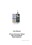
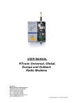
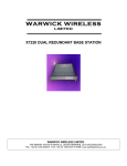
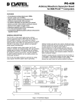
SX450G TRANSCEIVER
OPERATING INSTRUCTIONS
1892 1344
These operating instructions are intended to provide the user with sufficient information to
install and operate the unit correctly.
The Wood & Douglas SX450G is a high-performance synthesized UHF transceiver for
use in radio telemetry applications. The transceiver provides a maximum power output of
500mW and is designed to meet European standards ETS 300 220, ETS300 086 and
ETS300 339. The unit also complies with MPT1329 and as such does not require an
operating licence in the UK when programmed to operate over the appropriate frequency
range.
Two versions are available, the SX450GA and the SX450GC. They differ only in
connections, and are functionally identical.
Programming software (SXn50) is supplied to set channel frequencies and select the
operational channel, which can also be selected in hardware.
1892 1344 - SX450G Transceiver Operator Guide v1.7 / Nov 2007
1
Contents
Part One
The SX450G Radio Unit . . . . . . . . . . . . . . . . . . . . . . . . . . . . . . . . . . . . . . . . . . . . 3
DIMENSIONS AND FIXING . . . . . . . . . . . . . . . . . . . . . . . . . . . . . . . . . . . . . . . . . . 5
CONNECTIONS . . . . . . . . . . . . . . . . . . . . . . . . . . . . . . . . . . . . . . . . . . . . . . . . . . 7
POWER SUPPLY AND CURRENT CONSUMPTION . . . . . . . . . . . . . . . . . . . . . . 8
CHANNEL SELECTION DURING OPERATION . . . . . . . . . . . . . . . . . . . . . . . . . 10
RANGE INFORMATION . . . . . . . . . . . . . . . . . . . . . . . . . . . . . . . . . . . . . . . . . . . 12
Part Two
Programming . . . . . . . . . . . . . . . . . . . . . . . . . . . . . . . . . . . . . . . . . . . . . . . . . . .
CONNECTING THE UNIT TO A PC FOR PROGRAMMING . . . . . . . . . . . . . . . .
PROGRAMMING THE UNIT . . . . . . . . . . . . . . . . . . . . . . . . . . . . . . . . . . . . . . . .
DESCRIPTION OF USER INTERFACE . . . . . . . . . . . . . . . . . . . . . . . . . . . . . . .
TECHNICAL SPECIFICATION . . . . . . . . . . . . . . . . . . . . . . . . . . . . . . . . . . . . . .
13
15
17
20
23
APPENDIX 1: TTL TO RS232 ADAPTOR . . . . . . . . . . . . . . . . . . . . . . . . . . . . . . . . . . . 25
APPENDIX 2: PCS WITHOUT RS232 SERIAL PORTS (COM PORTS) . . . . . . . . . . . . 27
APPENDIX 3: TERMINAL KEYSTROKES . . . . . . . . . . . . . . . . . . . . . . . . . . . . . . . . . . 28
2
1892 1344 - SX450G Transceiver Operator Guide v1.7 / Nov 2007
Part One
The SX450G Radio Unit
v
Part Two, Programming, starts on page 13
1892 1344 - SX450G Transceiver Operator Guide v1.7 / Nov 2007
3
4
1892 1344 - SX450G Transceiver Operator Guide v1.7 / Nov 2007
DIMENSIONS AND FIXING
The SX450G is intended to fit easily and with minimum space requirements into the user's
own equipment housing.
Figure 1 SX450G fixing detail
Figure 2 - SX450GA connectors
Figure 3 - SX450GC connector
SX450GA mating connectors:
12W mating connector is MOLEX 51021-1200 with 50079 crimps.
8W mating connector is MOLEX 51021-0800 with 50079 crimps.
One each of these connectors, mounted onto a 200mm flying lead, is supplied with each
unit.
1892 1344 - SX450G Transceiver Operator Guide v1.7 / Nov 2007
5
The four corner tabs of the enclosure can be folded out to provide alternative mounting of
the unit, with fixing centres of 93.00 x 47.5mm using four M2 screws.
Figure 4 - Alternative mounting dimensions
6
1892 1344 - SX450G Transceiver Operator Guide v1.7 / Nov 2007
CONNECTIONS
The radio antenna connects via an MMCX 50O socket.
All other connections to the SX450GA transceiver are made via a 12-way connector PL1
and an 8-way connector PL2. These are single-in-line plugs which mate with the freeissued connectors with flying leads.
All other connections to the SX450GC transceiver are made via a 21-way SIL PCB
connector, PL1.
SX450GA SX450GC
NAME
PL1-1
PL1-1
0V
PL1-2
PL1-2
PL1-3
FUNCTION
REMARKS
0 volts
common ground
STBY
standby input
LOW (<+0.6V) = transceiver enabled
HIGH (>+2.0V) = standby mode
(internal pull-up, 40K to +4V max)
PL1-3
HI/LO
TX RF power select
input
>+2.0V = high power, <+0.8V = low power
(internal pull-down, 10K to 0V)
PL1-4
PL1-4
+Vin
positive supply input
+5.5 to +9.0 V input (-ve earth)
PL1-5
PL1-5
TXE
transmit enable input
HIGH (>+2.0V) = receiver enabled
LOW (<+0.8V) = transmitter enabled
(internal pull-up, 100K to +5V)
PL1-6
PL1-6
TXD/MS TXD - serial data
input
MS -
PL1-7
PL1-7
CS0/DT CS0 -
DT -
PL1-8
PL1-8
CS1/CK CS1 CK -
PL1-9
PL1-9
CS2/EN CS2 EN -
Serial data input = single 8-bit RS232 format
control word,
ie logic 1 = -V, logic 0 = +V (Maximum voltage
level is +12V; inverted TTL acceptable).
mode select,
i.e. channel
selection by
serial or
parallel data
input
Mode selected depends on the logic state at any
time:
HIGH > 1ms (>+2.0V) = parallel data input.
Defaults to this state if left open circuit (internal
pull-up, 50K to +3V).
LOW (<+0.8V) = serial data input; connection to
an RS232 output will automatically keep it at this
state.
channel
select input
(LSB)
synthesizer
serial data
input*
Channel select inputs use inverted 5V logic
levels;
HIGH (>+2.0V) = logic 0, LOW (<+0.8V) = logic 1
CS0 to CS5 are used for channel selection by 6bit parallel data
(Internal pull-ups 100K to +5V)
channel
select input
synthesizer
programme
clock *
(* DT/CK/EN inputs are used for direct control of
the synthesizer, this is a separate version of the
SX450.)
channel
select input
synthesizer
enable strobe
input*
PL1-10
PL1-10
CS3
channel select input
PL1-11
PL1-11
CS4
channel select input
1892 1344 - SX450G Transceiver Operator Guide v1.7 / Nov 2007
7
PL1-12
PL1-12
CS5
PL1-13
-
channel select input
(MSB)
not connected
RF DET TX RF present flag
output
-
PL2-1
PL1-14
PL2-2
PL1-15
PL2-3
PL1-16
SQO
squelch flag output
NPN open collector via 470O; ON = no signal,
OFF = signal present.
(NOTE: OFF when transceiver in standby mode)
PL2-4
PL1-17
OOL
out-of-lock output
NPN open collector via 470O; ON = out of lock
(NOTE: OFF when transceiver in standby mode)
PL2-5
PL1-18
DMOD
digital modulation
input **
+3V to +12V square wave, DC-coupled
** DMOD and AMOD may not be used
simultaneously. Leave unused input
unconnected.
PL2-6
PL1-19
AMOD
analogue modulation
input **
750mV p-p., AC-coupled (pre-settable 200mV to
3V p-p.)
** DMOD and AMOD may not be used
simultaneously. Leave unused input
unconnected.
PL2-7
PL1-20
RSSI
'S' meter output
0V to +3V output, rising with received signal level
(typ. 50dB range)
PL2-8
PL1-21
SQOR
squelch override input HIGH (>+2.0V) enables AF O/P regardless of
squelch state (RX only)
LOW (+0.8V or o/c) = normal operation
(internal pull-down, 70K to 0V)
AF O/P receiver audio output
HIGH (+5V, internal 10K pull-up) = TX RF
present
LOW (0V) = no TX RF
NOTE: only available when high TX RF power is
selected
600mV p.p. nom. into 10K; AC-coupled; Rout =
2K3.
POWER SUPPLY AND CURRENT CONSUMPTION
The SX450G requires a power supply of 5V to 15V DC (7.2V DC nominal). Because the
circuitry includes switched-mode power supplies, the current consumed varies inversely
with input voltage, and the external power supply must be capable of supplying the
corresponding current shown in the table below.
Input
5V
7.2V
12V
RX
45mA
30mA
25mA
TX 5mW
45mA
30mA
25mA
TX 500mW
400mA
250mA
200mA
State
Table 1 - Maximum supply current for various input voltages
Note: Connection to a vehicle supply without proper external transient suppression can
cause the internal configuration data to be corrupted.
8
1892 1344 - SX450G Transceiver Operator Guide v1.7 / Nov 2007
OVERVIEW OF FREQUENCIES AND PROGRAMMING
Each radio is built to order to cover a band (the switching bandwidth) of 20MHz within the
range 400 - 470 MHz. Each radio is also manufactured to work with a particular channel
width of 12.5kHz, 20kHz or 25kHz. These are fixed parameters, and cannot be changed
by the user.
Within the switching bandwidth, the unit can transmit and receive on any frequency
(provided it is a whole multiple of the comparison frequency), and up to 256 frequencies
can be stored as numbered channels 0 to 255.
There can also be an offset between transmit and receive frequencies. You can program
this offset, but both transmit and receive frequencies must remain within the switching
bandwidth for all channels. For example:
Switching bandwidth = 450MHz to 470MHz (fixed at manufacture)
Rx offset = +5MHz (programmed by user)
Therefore, maximum Tx frequency allowable = 470MHz - 5MHz = 465MHz.
During use, an operational channel can be selected at any time either using logic lines or
a serial data input. Logic lines can only select channels 0-63, serial commands can
select any channel.
Before the unit leaves the factory, each of 256 channels is allocated to a frequency, but
you can reprogram them if you wish.
You can program the unit in one of two modes:
v
256-channel mode: All 256 channels 0-255 can be programmed, but as a
block by entering a starting frequency and a step size, so that they contain
uniformly spaced frequencies. A single Rx offset applies to all channels.
v
80-channel mode: Each of channels 0-79 can be individually programmed
with any frequency, but the remaining channels 80-255 are not available for
use. Individual Rx offsets may be applied to channels.
One channel is then nominated as the operational channel.
To program a unit, you need to read the existing data from the it, edit the data using a
special program supplied by Wood & Douglas (SXn50.EXE), which runs on a PC under
Windows, then write the data back to the unit. This software provides facilities, such as a
list of valid frequencies, and the ability to copy one channel’s details to a number of
others, to make the job easier. Programming is described in Part Two of this manual,
starting on page 13.
1892 1344 - SX450G Transceiver Operator Guide v1.7 / Nov 2007
9
CHANNEL SELECTION DURING OPERATION
There are three ways to select a channel during operation:
v
v
v
In hardware, using six logic lines to select channels 0-63
Using the SXn50.EXE software and a serial connection from a PC to the unit
By sending a short serial data message to the unit from your own
equipment.
Parallel Channel Selection
v
Whenever PL1 pin 6 , Mode Select, is logic high (>2.0V) or open-circuit, the
channel is determined by the six channel select inputs - that is, parallel
channel selection is in operation.
v
Only channels 0 - 63 are available in this mode
The six channel select inputs are an inverse binary representation of the channel number,
that is, switch ON = input LOW = logic 1. If no connections are made, the unit therefore
defaults to channel 0.
Figure 5 - Parallel channel selection
Changes are implemented immediately.
The logic levels are :
10
LOW < 0.8V
HIGH > 2V or floating
1892 1344 - SX450G Transceiver Operator Guide v1.7 / Nov 2007
Serial Channel Selection
v
PL1 pin 6 must be logic low (<0.8V) to specify serial channel selection. This
is automatically the case when connected to an idle RS232 data output.
v
Channels 0 - 255 are available in this mode
The channel can be changed by sending a serial channel number as a single RS232 byte
on PL1 pin 6. The SXn50.exe software has the ability to do this, or you can use your own
equipment.
A simple adaptor such as the one in Figure 6 can be used to connect a PC to the unit.
(The programming adaptor of Figure 10, which can be purchased from Wood & Douglas,
product code 01106 1503 A, is also suitable.)
If you use a computer which does not have an RS232 serial port, then a USB-to-serial
adaptor is also needed, described in Appendix 2 on page 27.
The SX450G also requires a power supply capable of sourcing approximately 60mA.
Figure 6 - Serial channel change adaptor
The protocol is:
9600 baud, RS232 levels, 1 start bit - 8 bit data - no parity - 1 stop bit
Single-byte, channel number in binary, LSB first (decimal 0 to 255)
Idle state for at least 40ms before and after byte.
As soon as the message is recognised as a valid RS232 byte, the channel is changed.
No confirmation is required.
1892 1344 - SX450G Transceiver Operator Guide v1.7 / Nov 2007
11
When in this mode, the unit operates on the channel most recently selected in serial
mode. This setting is remembered during unit power off and any period of parallel
channel selection.
One way to send such a byte is to use a terminal such as a VT100 or emulator. Appendix
3 on page 28 shows the keystrokes necessary to generate the appropriate binary codes
for channels 0 to 127.
RANGE INFORMATION
The following table gives an indication of the typical ranges to be expected between a
transmitter and receiver that have simple end-fed dipole antennas.
The following assumptions have been made in the calculations:
Line-of-sight between antennas
0dB gain for the transmitter and receiver antennas
0dB loss for connectors and cables between the antenna and the radio connector
20dB fade and environmental margin
-100dBm received signal strength, allowing for digital and analogue signals
Range versus TX power
12
Frequency (MHz)
Power (mW)
Power (dBm)
Range (km)
458.5
1mW
0
0.5
458.5
10mW
10
1.7
458.5
100mW
20
5.3
458.5
500mW
27
11.9
1892 1344 - SX450G Transceiver Operator Guide v1.7 / Nov 2007
Part Two
Programming
1892 1344 - SX450G Transceiver Operator Guide v1.7 / Nov 2007
13
14
1892 1344 - SX450G Transceiver Operator Guide v1.7 / Nov 2007
CONNECTING THE UNIT TO A PC FOR PROGRAMMING
In order to program the unit, the unit and a PC (IBM-compatible personal computer) must
communicate via an asynchronous RS232 serial link.
The adaptors shown in the Appendix 1 on page 25 provide this link. A simple adaptor for
the SX450GA like that shown in Figure 10 can be purchased from Wood & Douglas,
product code 01106 1503 A.
If your computer does not have an RS232 serial port, then a USB-to-serial adaptor is
required, described in Appendix 2 on page 27.
The SX450G and adaptor also require a power supply capable of sourcing approximately
60mA.
1892 1344 - SX450G Transceiver Operator Guide v1.7 / Nov 2007
15
OBTAINING AND RUNNING THE PROGRAMMING SOFTWARE
1.
Download the latest version of the programming software SXn50.exe from the
Wood & Douglas site on the internet. The URL (address) is:
www.woodanddouglas.co.uk
(In case of difficulty, contact Sales at Wood & Douglas, contact details on the last
page of this manual.)
2.
Open the Zip file and run setup.exe, which will install the software for you.
3.
Run the SXn50.EXE program. It will run in a normal window with both mouse and
keyboard support.
At this stage, the main window is displayed as shown in Figure 7.
Figure 7 - Programming screen
The screen shows the default settings which are displayed whenever the SXn50 software
is run.
The menu bar at the top lists a number of headings, under which there are usually
additional menu items, representing actions. Below this, there is the Frequency Table.
The leftmost column lists the channel numbers, and beside channels 0 to 63 are listed the
inverted binary equivalents used for parallel selection. The next column, TX Frequency,
is used to set and display channel frequencies.
Use the Port Setup > Com Port > COM1 etc. menu selection to select the port to which
your adaptor is connected.
16
1892 1344 - SX450G Transceiver Operator Guide v1.7 / Nov 2007
PROGRAMMING THE UNIT
Three steps are necessary:
v
v
v
Upload (read) values from the unit
Edit the values
Download (write) values to the unit
Reading Current Unit Settings
First, you must read into the computer what is in the unit’s memory at present. To do this,
press F5 or select Link > Read from the Unit > Upload All from SX450G. The data
replaces the defaults on the screen and fills in the unit details.
v
The program insists that you do this before allowing you to reprogram the
unit to make it less likely that inappropriate values be entered.
v
However, once you have uploaded during a session, you may edit and
download the data to as many units as you wish.
Selecting Table Type
The SX450G can hold either a table of 80 individually-chosen Tx frequencies and Rx
offsets, or a table of 256 equally-spaced Tx frequencies all with the same Rx offset.
To select the table type, select Parameters > Number of Channels > 80 or 256.
Programming 256 Channels as a Block
It is necessary to specify the starting frequency (the lowest, corresponding to channel 0),
a spacing or step value, and an Rx offset. The spacing is expressed in multiples of the
Comparison Frequency (including 0, which makes all frequencies the same).
Double-click the Tx Frequency value for channel 0 in the main frequency table, which
brings up this dialog:
Figure 8 - Frequency Programming Dialog
1892 1344 - SX450G Transceiver Operator Guide v1.7 / Nov 2007
17
v
The list displays all valid values for the starting frequency, that is,
frequencies within the switching bandwidth which are multiples of the
Comparison Frequency.
Select a Table Start frequency from the list and a Table Step and click OK. The dialog is
removed and the main table shows the channel frequencies.
To set the Rx Offset for the whole table, select Parameters > Rx Offset and pick from the
list of possible values.
Programming Up To 80 Channels Individually
Double-click the Tx Frequency value for the channel to program in the main frequency
table, which brings up this dialog:
Figure 9 - Frequency Programming Dialog
v
Valid values for the starting frequency are frequencies within the switching
bandwidth which are multiples of the Comparison Frequency.
Select a Table Start frequency, ignoring the other parameters, and click OK. The dialog
is removed and the main table shows the channel with its new frequency.
To set the Rx Offset for the channel, select Parameters > Rx Offset and pick from the list
of possible values.
It is also possible to program a range of channels automatically in a similar way to the
256 channel block. In the Frequency Programming Dialog, select the range of channels
required (the From and To drop-downs), a Table Start and Channel Step, and click on
OK. The dialog is removed and the main table shows the channels with their new
frequencies.
It is not possible to select Rx Offset for a range of channels; this must be done
individually.
Setting Operational Channel
The unit must be told which of the 80 or 256 channel settings to use when it is powered
up. If PL1 pin 6 is open-circuit or logic high (>2.0V) for more than 1ms at power-up, then
18
1892 1344 - SX450G Transceiver Operator Guide v1.7 / Nov 2007
this is determined by hardware logic lines. Otherwise it depends on the most recent
serial command received, which is retained during power-down and during parallel
operation.
To set the operational channel, double-click on the channel number in the frequency
table. The row is highlighted to indicate that this is the operational channel.
Downloading New Settings to Unit
As yet, the settings have only been edited in the program. To download them to the unit,
press F6 or select Link > Write to the Unit > Download All to SX450G
v
This is only permitted if the Read from Unit command was previously used to
upload settings at some point during the session.
v
If you did not do this, save the configuration to disk, read the unit, and then
retrieve the configuration again. See below.
Completing Programming
This completes programming and the unit may be disconnected. It is not necessary to
switch off power or stop the program first.
Programming Further Units
Further units may be programmed by disconnecting one unit and connecting the next,
which may be done without switching the power off.
Proceed as above, downloading the configuration when all the channel parameters are
correct.
Saving and Retrieving Configurations
It is possible to save and retrieve configurations on disk for later use.
To save a new configuration, select File > Save Parameters As. To save a previously
saved configuration, select File > Save Parameters.
To retrieve a configuration, overwriting any existing configuration on the screen, select
File > Load Parameters.
v
This feature is also useful if you find that you cannot program a unit because
you omitted to read it first. Save your edited configuration, read the unit,
then retrieve the configuration.
1892 1344 - SX450G Transceiver Operator Guide v1.7 / Nov 2007
19
DESCRIPTION OF USER INTERFACE
Top Level Menu Bar (Outer Window)
File
Load Parameters
Load a pre-stored set of parameters in a *.WXP file from a standard
File Open dialog.
Save Parameters
Save the current set of parameters, overwriting the previous ones.
Save Parameters As
Save the current set of parameters under a new name. A
default name is given which you can change, and you can
navigate to the directory of your choice.
Saving Options
Controls the format in which information is saved. Provided you are
programming an SX450G, you should save in the default Format 2,
allowing 80 channels with IF offsets. Format 1 is only used with
legacy SX450 modules.
Save Report File
Save the current report. A default name is given which you can
change, and you can navigate to the directory of your choice.
Print
Print the current set of parameters; only available when Report File
window is open. The currently selected Windows default printer will
be used.
Update Firmware
Replace the firmware in a unit with a binary file which you can choose
from a standard File Open dialog.
Caution:
Exit Program
This can render a unit unusable and require repairs
by Wood & Douglas if done incorrectly.
Exit the program.
Parameters
Reference Osc
Fixed in hardware, display only.
Comparison Frequency
Fixed in hardware, display only.
Channel Step Size
Multiple of the Comparison Frequency
Number of Channels
80 (individually programmed) or 256 (programmed as a
sequence)
Select Rx Offset
A number of choices, multiples of the Comparison Frequency,
are offered.
20
1892 1344 - SX450G Transceiver Operator Guide v1.7 / Nov 2007
Link
Read from Unit
Reads data from the unit into the program, which is then
displayed on the screen. Until this command has been
issued, no data can be downloaded to the unit.
Write to Unit
Downloads data from the program to the unit. This command
can only be issued after a Read from Unit command has been
issued during the current session.
Send e-mail
Causes your default email application to create a new blank
email addressed to Wood & Douglas technical support with
the subject “SNx50".
Port Setup
Com Port
Allows you to select one of the COM (serial) ports on your
machine to communicate with the SX450G.
View
Main Menu
Turns on and off display of the Main Menu window.
Internal EEPROM
This displays the contents of the unit’s EEPROM in a separate
window. The data displayed is for the functions and channels
displayed on the main screen at that time. Data can be handmodified by highlighting the data and over-writing it. Note that the
type of data in each field is displayed at the bottom of the window.
Caution:
This should only be carried out with full knowledge
of the internal working of the SX450G. It can render
a unit unusable and require repairs by Wood &
Douglas if done incorrectly.
While this window is displayed, no access is available to the main
window. The window must be cleared down by clearing the check
mark against it in the View menu.
Report File
Displays a report on the current setup shown in the main menu which can
be printed if you wish.
Help
About
Displays information about Wood & Douglas, including website and
contact details.
Check for GUI Update
Checks the Wood & Douglas website for updates and offers to
update your GUI if appropriate.
1892 1344 - SX450G Transceiver Operator Guide v1.7 / Nov 2007
21
Main Menu - Frequency Table (Inner Window)
Channel Table
The Channel Table shows the following parameters for each of the 80 or 256 channels,
as appropriate:
Channel No
Parallel (logic lines) code required to select this channel, where 1
represents a connection to 0v, closed contact to 0V or logic low.
Tx Frequency
The transmit frequency.
Rx Frequency
The receive frequency (which may be different if an Rx offset has
been selected).
Rx Offset
The amount by which the Rx frequency is higher than the Tx
frequency.
Unit Information
This box is display only and cannot be edited.
File Name
The name of the firmware running in the unit.
File Version
The version of firmware running in the unit.
File Date
The date of the firmware running in the unit
S/N
The serial number of the unit.
Number of Channels
How many channels are programmed and may be selected
during operation.
Maximum Frequency
The software assumes a 5MHz switching bandwidth to
calculate the Maximum Frequency from the Minimum
Frequency and uses this to calculate the frequencies in the
drop-down list displayed when selecting channel frequencies.
Minimum Frequency
The minimum frequency refers to the transmit band, and is
used by the software as a base-line for all other frequency
information. The software will not allow a channel to be set to
a frequency below this minimum (or, in the case of a received
channel, this frequency plus the receive offset). This
frequency is stored in the non-volatile EEPROM in the unit.
22
1892 1344 - SX450G Transceiver Operator Guide v1.7 / Nov 2007
TECHNICAL SPECIFICATION
General
Frequency range
A band within the range 400-490MHz, to order
Switching bandwidth
15 or 20MHz depending on band ordered.
Frequency stability
+2.5ppm over operating temperature
Channel switching delay
100ms maximum (over 20MHz switching bandwidth)
Channel programming
Table of 256 equally-spaced frequencies with common RxTx offset, or table of 80 individually-programmed
frequencies and Rx-Tx offsets.
Channel selection
64 channels maximum using 6-bit parallel logic line input.
256 channels maximum using serial RS232 data word.
Serial/parallel selection switchable in real time.
Channel spacing
12.5kHz/20kHz/25kHz available
Modulation type
F1D/F2D/F3D
Spurious emissions
(conducted & radiated) In accordance with ETSI/CEPT
Supply voltage
5 to 15V DC negative earth
Supply current at 7.2V
30mA typical (receive), 250mA typical for 500mW output
(transmit)
Interface connections
21 pin SIL PCB connection (SX450GC)
1 x 8 + 1 x 12 way 1.27mm pitch Molex right angle plug
with mating connector + 200mm lead (SX450GA)
RF connection
PC mounted MMCX socket (200mm RG178 lead supplied).
Operating temperature
-25%C to +55%C
Storage temperature
-30%C to +70%C
Size overall
85 x 55 x 12.7mm
Weight
70g
Type approvals
ETS300 220, ETS300 339 (EMC), ETS300 086, UK
MPT1329
1892 1344 - SX450G Transceiver Operator Guide v1.7 / Nov 2007
23
Transmitter
RF output power into 50O
500mW (HI) (+0/-1.5dB) 5mW (LO)
TX/RX switching time
<25ms
Modulation input
analogue
digital
750mV p-p, AC-coupled
+3 to +12V square wave DC-coupled
Frequency response
9Hz to 3kHz at -3dB (analogue input)
(optional extended response to 6kHz for 9600 baud
GMSK)
Frequency deviation
25kHz channel spacing
20kHz channel spacing
12.5kHz channel spacing
+3.0kHz nominal (+4.0kHz max)
+2.3kHz nominal (+3.0kHz max)
+1.5kHz nominal (+2.0kHz max)
Adjacent channel power
<200nW (-37dBm)
Facilities
RF detect output (+5V = TX on) (HI power only)
Receiver
Sensitivity
<-115dBm for 12dB SINAD (Measured with flat
audio response)
<-107dBm for 20dB SINAD (Measured with flat
audio response)
Image rejection
>70dB
Intermodulation rejection
>65dB
Blocking
>84dB
Spurious rejection
>70dB
Intermediate frequencies
45MHz and 455kHz
Adjacent channel rejection
12.5kHz channel spacing
20/25kHz channel spacing
>60dB
>70dB
Recovered audio level
600mV p-p (+20%) into 10K
Squelch type
Noise operated
Squelch output
NPN open collector via 470O
ON = no signal, OFF = signal present
Facilities
RSSI output (0 to +3V nominal from 2K2 source)
Squelch override input
STBY input Standby current
150uA typ for HI/LO input = 0V
24
1892 1344 - SX450G Transceiver Operator Guide v1.7 / Nov 2007
APPENDIX 1: TTL TO RS232 ADAPTOR
These adaptors are used to connect a PC to the SX450G when programming a unit.
Many PCs do not require true RS232, and will work with the simple adaptor of Figure 10.
The transistor used must have a gain of at least 30, and the power supply must be 12V.
Figure 10 - Simple programming adaptor
Figure 11 shows the circuit of an adaptor providing true RS232.
Figure 11 - Programming adaptor (True RS232)
1892 1344 - SX450G Transceiver Operator Guide v1.7 / Nov 2007
25
A suitable inverting TTL to RS232 buffer circuit using the industry-standard MAX232 part
is shown in Figure 12.
Figure 12 - Suggested RS232 buffer circuit
The MAX232 is obtainable from many component suppliers, e.g. RS Components stock
no. 655-290.
v
26
Note that the MAX232 has an absolute maximum supply voltage of 6V, and
therefore the SX450G and the adaptor should be run from a 5V DC supply.
1892 1344 - SX450G Transceiver Operator Guide v1.7 / Nov 2007
APPENDIX 2: PCS WITHOUT RS232 SERIAL PORTS (COM PORTS)
Some laptops and PCs are no longer supplied with RS232 serial ports; in this case, a
USB-to-RS232 adaptor can be used to connect the PC running SXn50.EXE to the
SX450G.
Wood & Douglas have tried a range of adaptors and recommend the EasySync
US232B/LC, which has been tested with Windows 2000 and Windows XP.
v
1.
Further information and a downloadable manual can be found at
www.easysync.co.uk/usbrs232_single.html.
Installing the Adaptor
The adaptor is supplied with printed instructions and an installation disc. Before
plugging the adaptor into the host computer’s USB port, insert the installation disc
into the PC’s CD-ROM drive, then follow the on-screen instructions for your version
of Windows.
When the installation is complete, proceed as follows to find its COM port number:
1.
Open the Control Panel (Start, Settings, Control Panel) and open the
System control.
2.
Select Hardware, Device Manager and expand the Ports (COM & LPT)
folder.
3.
Find the entry labelled “USB Serial Port (COM n)” and note the number n.
4.
Close the Device Manager, System and Control Panel windows.
If there is no USB Serial Port (COM n) entry, remove and re-insert the adaptor in
the USB port. If this fails to clear the problem, uninstall the adaptor and repeat this
section.
2.
Connecting the Command Centre PC and the SX450G
With the USB Serial Port Adaptor plugged into the PC USB port, connect the
adaptor cable (Figure 9) from the SX450G serial port to the USB adaptor serial
port and the power supply, and turn the power supply on.
3.
Configuring the GUI
Run the GUI, select Port Setup from the menu bar and click Com Port. From the
list of ports, select the number of the COM port found in the previous procedure.
When the GUI sends data to the unit, the red LED on the adaptor flashes. When
the unit replies, the green LED on the adaptor flashes.
1892 1344 - SX450G Transceiver Operator Guide v1.7 / Nov 2007
27
APPENDIX 3: TERMINAL KEYSTROKES
These keystrokes generate a serial byte output from a standard (e.g. VT100) terminal
which can be used to select channels 0 to 127 in serial mode. For example, to select
channel 36, key Shift+4 (dollars), which generates the byte 00100100, decimal 36. Other
keystrokes may generate codes 128 to 255, depending on the terminal.
No
0
1
2
3
4
5
6
7
8
9
10
11
12
13
14
15
16
17
18
19
20
21
22
23
24
25
26
27
28
29
30
31
Keystroke
Ctrl @
Ctrl A
Ctrl B
Ctrl C
Ctrl D
Ctrl E
Ctrl F
Ctrl G
Ctrl H
Ctrl I
Ctrl J
Ctrl K
Ctrl L
Ctrl M
Ctrl N
Ctrl O
Ctrl P
Ctrl Q
Ctrl R
Ctrl S
Ctrl T
Ctrl U
Ctrl V
Ctrl W
Ctrl X
Ctrl Y
Ctrl Z
Ctrl [
Ctrl \
Ctrl ]
Ctrl ^
Ctrl _
32
33
34
35
36
37
38
39
40
41
42
43
44
45
46
47
48
49
50
51
52
53
54
55
56
57
58
59
60
61
62
63
64
<SPACE>
Shift 1
Shift ‘
Shift 3
Shift 4
Shift 5
Shift 7
‘
Shift 9
Shift 0
Shift 8
Shift =
,
.
/
0
1
2
3
4
5
6
7
8
9
Shift ;
;
Shift ,
0
Shift .
Shift /
Shift 2
Wood & Douglas Ltd, Lattice House
Baughurst, Tadley, Hants, RG26 5LP
Tel:+44 (0)118 981 1444 Fax: +44 (0)118 981 1567
email: [email protected]
website: www.woodanddouglas.co.uk
28
65
66
67
68
69
70
71
72
73
74
75
76
77
78
79
80
81
82
83
84
85
86
87
88
89
90
91
92
93
94
95
96
97
Shift A
Shift B
Shift C
Shift D
Shift E
Shift F
Shift G
Shift H
Shift I
Shift J
Shift K
Shift L
Shift M
Shift N
Shift O
Shift P
Shift Q
Shift R
Shift S
Shift T
Shift U
Shift V
Shift W
Shift X
Shift Y
Shift Z
[
\
]
Shift 6
Shift `
A
98
99
100
101
102
103
104
105
106
107
108
109
110
111
112
113
114
115
116
117
118
119
120
121
122
123
124
125
126
127
B
C
D
E
F
G
H
I
J
K
L
M
N
O
P
Q
R
S
T
U
V
W
X
Y
Z
Shift [
Shift \
Shift ]
Shift `
Del
© Wood & Douglas Ltd 2007
1892 1344 - SX450G Transceiver Operator Guide v1.7 / Nov 2007