1
AT Commands for
RCV56ACx, RCV336ACx,
RCV288ACx, and RCV144ACx Modems
Reference Manual
(Preliminary)
Order No. 1048
Rev. 4, February 20, 1997
AT Command Reference Manual
NOTICE
Information furnished by Rockwell International Corporation is believed to be accurate and reliable. However, no
responsibility is assumed by Rockwell International for its use, nor any infringement of patents or other rights of
third parties which may result from its use. No license is granted by implication or otherwise under any patent
rights of Rockwell International other than for circuitry embodied in Rockwell products. Rockwell International
reserves the right to change circuitry at any time without notice. This document is subject to change without
notice.
K56flex is a trademark of Lucent Technologies and Rockwell International.
ConfigurACE is a trademark of Rockwell International.
MNP is a registered trademark of Microcom, Inc.
Hayes is a registered trademark of Hayes Microcomputer Products, Inc.
ii
1048
AT Command Reference Manual
PREFACE
This manual supersedes the following manuals:
1.
AT Command Reference Manual for the RC288ACi and RC288ACL Modem Families (Order No. 1048, Rev.3, January
9, 1996).
2.
Addendum 1 to AT Commands for RC288ACx and RC144ACx Modem Families (Order No. 1048R3A1, Rev.1, August
2, 1996).
This revision incorporates Addendum 1 to AT Commands for RC288ACx and RC144ACx Modem Families (Order No.
1048R3A1, Rev.1, August 2, 1996); adds K56flex command (+MS), connect and carrier messages; and adds V.80
commands.
1048
iii
AT Command Reference Manual
This page is intentionally blank.
iv
1048
AT Command Reference Manual
Table of Contents
1. INTRODUCTION ...........................................................................................................................................................1-1
1.1 OVERVIEW ..........................................................................................................................................................1-1
1.1.1 Command Syntax ........................................................................................................... .........................1-1
1.1.2 Command Descriptions............................................................................................................................1-1
1.1.3 Call Progress and Blacklisting Parameters ...............................................................................................1-2
1.1.4 ConfigurACE II for Windows Utility Program............................................................................... ..............1-2
1.2 REFERENCE DOCUMENTATION ........................................................................................................................1-2
2. COMMAND SYNTAX ....................................................................................................................................................2-1
2.1 DTE/DCE INTERCHANGE CIRCUITS...................................................................................................................2-1
2.2 COMMAND SYNTAX AND GUIDELINES..............................................................................................................2-1
2.2.1 DTE Commands ......................................................................................................................................2-1
2.2.2 DTE Command Lines............................................................................................................................... 2-1
2.3 AT COMMAND GUIDELINES ............................................................................................................................... 2-1
2.3.1 Basic Command Syntax...........................................................................................................................2-1
2.3.2 Extended Command Syntax ....................................................................................................................2-1
3. AT COMMAND SET......................................................................................................................................................3-1
3.1 AT COMMAND GUIDELINES ............................................................................................................................... 3-1
3.1.1 AT Commands, DTE Adaption .................................................................................................................3-1
3.1.2 AT Command Format ........................................................................................................ ......................3-1
3.1.3 Escape Code Sequence ..........................................................................................................................3-1
3.2 AT COMMAND SET .............................................................................................................................................3-2
3.2.1 AT Commands ........................................................................................................................................3-2
A/ - Re-execute Command ........................................................................................................ ...........3-2
AT= x - Write to Selected S-Register ........................................................................................... .........3-2
AT? - Read Selected S-Register ...........................................................................................................3-2
A - Answer ..................................................................................................................... ......................3-2
Bn - CCITT or Bell ................................................................................................................................3-2
Cn - Carrier Control ........................................................................................................... ...................3-3
Dn - Dial ...............................................................................................................................................3-3
En - Command Echo ............................................................................................................................3-4
Fn - Select Line Modulation (RC144 Models Only) ................................................................................3-5
Hn - Disconnect (Hang-Up)...................................................................................................................3-6
In - Identification ...................................................................................................................................3-6
Ln - Speaker Volume ............................................................................................................................3-6
Mn - Speaker Control ........................................................................................................... ................3-7
Nn - Automode Enable .........................................................................................................................3-7
On - Return to On-Line Data Mode .......................................................................................................3-7
P - Set Pulse Dial Default .....................................................................................................................3-8
Qn - Quiet Results Codes Control............................................................................................... ..........3-8
Sn - Read/Write S-Register ..................................................................................................................3-8
T - Set Tone Dial Default ......................................................................................................................3-9
Vn - Result Code Form .......................................................................................................... ...............3-9
Wn - Connect Message Control ............................................................................................................3-9
Xn - Extended Result Codes............................................................................................................... 3-10
Yn - Long Space Disconnect............................................................................................................... 3-13
Zn - Soft Reset and Restore Profile ............................................................................................ ........3-13
3.2.2 AT& Commands ....................................................................................................................................3-14
&Cn - RLSD (DCD) Option.................................................................................................................. 3-14
&Dn - DTR Option ..............................................................................................................................3-14
&Fn - Restore Factory Configuration (Profile).................................................................................. ....3-14
&Gn - Select Guard Tone ........................................................................................................ ...........3-15
1048
v
AT Command Reference Manual
&Jn - Telephone Jack Control............................................................................................................. 3-15
&Kn - Flow Control .............................................................................................................................3-15
&Ln - Leased Line Operation .............................................................................................................. 3-15
&Mn - Asynchronous/Synchronous Mode Selection ............................................................................ 3-16
&Pn - Select Pulse Dial Make/Break Ratio .......................................................................................... 3-16
&Qn - Sync/Async Mode.......................................................................................................... ...........3-17
&Rn - RTS/CTS Option....................................................................................................................... 3-18
&Sn - DSR Override ........................................................................................................................... 3-18
&Tn - Test and Diagnostics................................................................................................................. 3-18
&V - Display Current Configuration and Stored Profiles ....................................................................... 3-19
3.2.3 &V1 - Display Last Connection Statistics ................................................................................................ 3-19
&Wn - Store Current Configuration .............................................................................................. .......3-20
&Xn - Select Synchronous Clock Source............................................................................................. 3-20
&Yn - Designate a Default Reset Profile.............................................................................................. 3-20
&Zn=x - Store Telephone Number ...................................................................................................... 3-20
3.2.4 AT% Commands ................................................................................................................................... 3-21
%En - Enable/Disable Line Quality Monitor and Auto-Retrain or Fallback/Fall Forward ........................ 3-21
%L - Line Signal Level ........................................................................................................................ 3-21
%Q - Line Signal Quality..................................................................................................................... 3-21
%7 - Plug and Play Serial Number ...................................................................................................... 3-22
%8 - Plug and Play Vendor ID and Product Number............................................................................ 3-22
3.2.5 AT\ Commands ..................................................................................................................................... 3-23
\Kn - Break Control .............................................................................................................................3-23
\Nn - Operating Mode .........................................................................................................................3-24
\Vn - Single Line Connect Message Enable......................................................................................... 3-24
3.2.6 AT+ Commands .................................................................................................................................... 3-25
+MS - Select Modulation..................................................................................................................... 3-25
+Hn - Enable/Disable RPI and DTE Speed.......................................................................................... 3-28
3.2.7 AT** Command ..................................................................................................................................... 3-29
** - Download to Flash Memory ..........................................................................................................3-29
3.2.8 AT- Commands ..................................................................................................................................... 3-30
-SDR=n - Enable/Disable Distinctive Ring ........................................................................................... 3-30
3.3 ERROR DETECTION AND DATA COMPRESSION COMMANDS....................................................................... 3-31
3.3.1 AT% Commands ................................................................................................................................... 3-31
%C - Enable/Disable Data Compression ............................................................................................. 3-31
3.3.2 AT\ Commands ..................................................................................................................................... 3-31
\An - Select Maximum MNP Block Size............................................................................................... 3-31
\Bn - Transmit Break to Remote..........................................................................................................3-31
3.4 MNP 10 COMMANDS.........................................................................................................................................3-32
3.4.1 AT) Commands ..................................................................................................................................... 3-32
)Mn - Enable Cellular Power Level Adjustment.................................................................................... 3-32
*Hn - Link Negotiation Speed .............................................................................................................. 3-32
-Kn - MNP Extended Services ............................................................................................................ 3-32
-Qn - Enable Fallback to V.22 bis/V.22......................................................................................... .......3-32
-SEC=n - Enable/Disable MNP10-EC.................................................................................................. 3-33
@Mn - Initial Cellular Power Level Setting........................................................................................... 3-33
:E - Compromise Equalizer Enable Command..................................................................................... 3-33
3.5 W-CLASS COMMANDS......................................................................................................................................3-34
3.5.1 AT* Commands ..................................................................................................................................... 3-34
*B - Display Blacklisted Numbers ........................................................................................................ 3-34
*D - Display Delayed Numbers............................................................................................................ 3-34
*NCn - Country Select ........................................................................................................................ 3-35
3.6 CALLER ID COMMANDS ...................................................................................................................................3-36
3.6.1 AT#CID Command ................................................................................................................................3-36
#CIDn - Caller ID ................................................................................................................................3-36
Inquiries .............................................................................................................................................3-36
Formatted Form Reporting..................................................................................................................3-36
vi
1048
AT Command Reference Manual
Example of Formatted Form Reporting ............................................................................................ ...3-37
Unformatted Form Reporting ..............................................................................................................3-37
Example of Unformatted Form Reporting .......................................................................................... ..3-37
3.7 CELLULAR COMMANDS....................................................................................................................................3-38
3.7.1 Cellular Phone Drivers ........................................................................................................................... 3-38
3.7.2 Cellular Commands ............................................................................................................................... 3-38
^C2 - Download Cellular Phone Driver ................................................................................................ 3-38
^I - Identify Cellular Phone Driver............................................................................................ ............3-38
^T6 - Indicate Status of Cellular Phone ............................................................................................... 3-39
3.7.3 Operation .............................................................................................................................................. 3-39
Modem Configuration ......................................................................................................................... 3-39
Fax Configuration ............................................................................................................................... 3-40
Cellular Phone Configuration .............................................................................................................. 3-40
3.8 AT COMMAND RESULT CODES ....................................................................................................................... 3-42
OK (0) 3-42
CONNECT (1) ....................................................................................................................................3-42
RING (2) ....................................................................................................................... ..................... 3-42
NO CARRIER (3)................................................................................................................................3-42
ERROR (4).........................................................................................................................................3-42
CONNECT 1200 (5)............................................................................................................................3-42
NO DIALTONE (6)..............................................................................................................................3-42
BUSY (7)............................................................................................................................................3-43
NO ANSWER (8) ................................................................................................................................3-43
CONNECT 0600 (9)............................................................................................................................3-43
CONNECT 2400 (10).......................................................................................................................... 3-43
CONNECT 4800 (11).......................................................................................................................... 3-43
CONNECT 9600 (12).......................................................................................................................... 3-43
CONNECT 7200 (13).......................................................................................................................... 3-43
CONNECT 12000 (14)........................................................................................................................ 3-43
CONNECT 14400 (15)........................................................................................................................ 3-43
CONNECT 19200 (16)........................................................................................................................ 3-43
CONNECT 38400 (17)........................................................................................................................ 3-44
CONNECT 57600 (18)........................................................................................................................ 3-44
CONNECT 115200 (19)...................................................................................................................... 3-44
CONNECT 75TX/1200RX (22)............................................................................................................ 3-44
CONNECT 1200TX/75RX (23)............................................................................................................ 3-44
DELAYED (24) ...................................................................................................................................3-44
BLACKLISTED (32) ............................................................................................................................3-44
FAX (33).............................................................................................................................................3-44
DATA (35) ..........................................................................................................................................3-44
CARRIER 300 (40) .............................................................................................................................3-44
CARRIER 1200/75 (44) ...................................................................................................................... 3-44
CARRIER 75/1200 (45) ...................................................................................................................... 3-44
CARRIER 1200 (46) ........................................................................................................................... 3-44
CARRIER 2400 (47) ........................................................................................................................... 3-44
CARRIER 4800 (48) ........................................................................................................................... 3-44
CARRIER 7200 (49) ........................................................................................................................... 3-45
CARRIER 9600 (50) ........................................................................................................................... 3-45
CARRIER 12000 (51) ......................................................................................................................... 3-45
CARRIER 14400 (52) ......................................................................................................................... 3-45
CARRIER 16800 (53) ......................................................................................................................... 3-45
CARRIER 19200 (54) ......................................................................................................................... 3-45
CARRIER 21600 (55) ......................................................................................................................... 3-45
CARRIER 24000 (56) ......................................................................................................................... 3-45
CARRIER 26400 (57) ......................................................................................................................... 3-45
CARRIER 28800 (58) ......................................................................................................................... 3-45
CONNECT 16800 (59)........................................................................................................................ 3-45
CONNECT 21600 (61)........................................................................................................................ 3-45
CONNECT 24000 (62)........................................................................................................................ 3-45
1048
vii
AT Command Reference Manual
CONNECT 26400 (63)........................................................................................................................ 3-45
CONNECT 28800 (64)........................................................................................................................ 3-46
COMPRESSION: CLASS 5 (66) ......................................................................................................... 3-46
COMPRESSION: V.42 bis (67) ........................................................................................................... 3-46
COMPRESSION: NONE (69) ............................................................................................................. 3-46
PROTOCOL: NONE (70) ....................................................................................................................3-46
PROTOCOL: LAPM (77) ....................................................................................................................3-46
CARRIER 31200 (78) ......................................................................................................................... 3-46
CARRIER 33600 (79) ......................................................................................................................... 3-46
PROTOCOL: ALT (80)........................................................................................................................3-46
PROTOCOL: ALT-CELLULAR (81)..................................................................................................... 3-46
CONNECT 33600 (84)........................................................................................................................ 3-46
CONNECT 31200 (91)........................................................................................................................ 3-46
CARRIER 32000 (150) ....................................................................................................................... 3-46
CARRIER 34000 (151) ....................................................................................................................... 3-46
CARRIER 36000 (152) ....................................................................................................................... 3-47
CARRIER 38000 (153) ....................................................................................................................... 3-47
CARRIER 40000 (154) ....................................................................................................................... 3-47
CARRIER 42000 (155) ....................................................................................................................... 3-47
CARRIER 44000 (156) ....................................................................................................................... 3-47
CARRIER 46000 (157) ....................................................................................................................... 3-47
CARRIER 48000 (158) ....................................................................................................................... 3-47
CARRIER 50000 (159) ....................................................................................................................... 3-47
CARRIER 52000 (160) ....................................................................................................................... 3-47
CARRIER 54000 (161) ....................................................................................................................... 3-47
CARRIER 56000 (162) ....................................................................................................................... 3-47
CONNECT 32000 (165)...................................................................................................................... 3-47
CONNECT 34000 (166)...................................................................................................................... 3-47
CONNECT 36000 (167)...................................................................................................................... 3-47
CONNECT 38000 (168)...................................................................................................................... 3-48
CONNECT 40000 (169)...................................................................................................................... 3-48
CONNECT 42000 (170)...................................................................................................................... 3-48
CONNECT 44000 (171)...................................................................................................................... 3-48
CONNECT 46000 (172)...................................................................................................................... 3-48
CONNECT 48000 (173)...................................................................................................................... 3-48
CONNECT 50000 (174)...................................................................................................................... 3-48
CONNECT 52000 (175)...................................................................................................................... 3-48
CONNECT 54000 (176)...................................................................................................................... 3-48
CONNECT 56000 (177)...................................................................................................................... 3-48
CONNECT 230400 (20)...................................................................................................................... 3-48
+FCERROR (+F4) ..............................................................................................................................3-48
3.9 AUDIOSPAN AND DSVD COMMANDS .............................................................................................................. 3-49
3.9.1 Commands Supported by Both AudioSpan and DSVD ........................................................................... 3-49
-SMS= x, y, z, t - Select AudioSpan/DSVD Mode ................................................................................3- 49
#VLS = x - Voice Line Select............................................................................................................... 3-50
3.9.2 Commands Supported Only by DSVD.................................................................................................... 3-50
-SSE= x - Enable/Disable DSVD ......................................................................................................... 3-50
3.9.3 Commands Supported Only by AudioSpan ............................................................................................ 3-51
-SQS= x, y - Select AudioSpan Modulation ......................................................................................... 3-51
3.9.4 Examples ..............................................................................................................................................3-53
3.10 SYNCHRONOUS ACCESS MODE ................................................................................................................... 3-58
3.10.1 Synchronous Access Mode Commands ............................................................................................... 3-58
+ES - Enable Synchronous Access Mode ........................................................................................... 3-58
+ESA - Configure Synchronous Access Submode............................................................................... 3-59
+ ITF - Transmit Flow Control Thresholds ........................................................................................... 3-61
4. S-REGISTERS ..............................................................................................................................................................4-1
4.1 FACTORY DEFAULTS .........................................................................................................................................4-1
4.2 S-REGISTER DEFINITIONS.................................................................................................................................4-4
viii
1048
AT Command Reference Manual
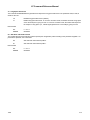
S0 - Number of Rings to Auto-Answer ............................................................................................ ......4-4
S1 - Ring Counter.................................................................................................................................4-4
S2 - Escape Character .......................................................................................................... ...............4-4
S3 - Carriage Return Character ............................................................................................................4-4
S4 - Line Feed Character......................................................................................................................4-4
S5 - Backspace Character ....................................................................................................................4-4
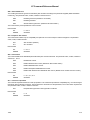
S6 - Wait Time for Dial Tone Before Blind Dialing, or After “W” Dial Modifier (W-Class Models).............4-5
S7 - Wait Time For Carrier After Dial, For Silence, or For Dial Tone After “W” Dial Modifier (US Models)4-5
S8 - Pause Time For Dial Delay ............................................................................................................4-5
S9 - Carrier Detect Response Time .............................................................................................. ........4-5
S10 - Lost Carrier To Hang Up Delay....................................................................................................4-5
S11 - DTMF Tone Duration...................................................................................................................4-5
S12 - Escape Prompt Delay (EPD) .......................................................................................................4-6
S13 - Reserved ....................................................................................................................................4-6
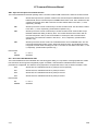
S14 - General Bit Mapped Options Status........................................................................................ .....4-6
S15 - Reserved ....................................................................................................................................4-6
S16 - General Bit Mapped Test Options Status .....................................................................................4-7
S17 - Reserved ....................................................................................................................................4-7
S18 - Test Timer...................................................................................................................................4-7
S19 - AutoSync Bit Mapped Options .............................................................................................. .......4-8
S20 - AutoSync HDLC Address or BSC Sync Character........................................................................4-8
S21 - V.24/General Bit Mapped Options Status.....................................................................................4-9
S22 - Speaker/Results Bit Mapped Options Status..............................................................................4-10
S23 - General Bit Mapped Options Status........................................................................................ ...4-11
S24 - Sleep Inactivity Timer ................................................................................................................ 4-11
S25 - Delay To DTR ........................................................................................................................... 4-11
S26 - RTS to CTS Delay..................................................................................................................... 4-11
S27 - Bit Mapped Options Status ........................................................................................................4-12
S28 - Bit Mapped Options Status ........................................................................................................4-13
S29 - Flash Dial Modifier Time ............................................................................................................ 4-13
S30 - Disconnect Inactivity Timer.............................................................................................. ..........4-13
S31 - Bit Mapped Options Status ........................................................................................................4-14
S32 - XON Character .........................................................................................................................4-14
S33 - XOFF Character........................................................................................................... .............4-14
S34-S35 - Reserved ........................................................................................................................... 4-14
S36 - LAPM Failure Control ................................................................................................................ 4-15
S37 - Desired Line Connection Speed................................................................................................. 4-16
S38 - Delay Before Forced Hang Up................................................................................................... 4-17
S39 - Flow Control Bit Mapped Options Status.................................................................................... 4-17
S40 - General Bit Mapped Options Status........................................................................................ ...4-18
S41 - General Bit Mapped Options Status........................................................................................ ...4-19
S46 - Data Compression Control ........................................................................................................ 4-19
S48 - V.42 Negotiation Action ............................................................................................................. 4-19
S82 - Break Handling Options............................................................................................................. 4-20
S86 - Call Failure Reason Code.......................................................................................................... 4-20
S91 - PSTN Transmit Attenuation Level.............................................................................................. 4-20
S92 - Fax Transmit Attenuation Level .................................................................................................4-20
S95 - Extended Result Codes ............................................................................................................. 4-21
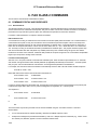
5. FAX CLASS 1 COMMANDS .........................................................................................................................................5-1
5.1 FAX I/O PROCESSING ......................................................................................................... ...............................5-1
5.1.1 DTE-to-Modem Transmit Data Stream ........................................................................................ .............5-1
5.1.2 Modem-to-DTE Receive Data Stream ......................................................................................................5-1
5.1.3 Fax Mode Selection .................................................................................................................................5-1
5.1.4 Fax Origination ........................................................................................................................................5-1
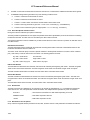
5.1.5 Fax Answering.........................................................................................................................................5-2
5.1.6 Fax Control Transmission ........................................................................................................................5-2
5.1.7 Fax Control Reception .............................................................................................................................5-2
5.1.8 Fax Data Transmission ............................................................................................................................5-3
1048
ix
AT Command Reference Manual
5.1.9 Fax Data Reception .................................................................................................................................5-3
5.2 COMMANDS ........................................................................................................................................................5-4
+FCLASS=n - Select Service Class ......................................................................................................5-4
+F<command>? - Report Active Configuration......................................................................................5-4
+F<command>=? - Report Operating Capabilities.................................................................................5-4
+FAE=n - Data/Fax Auto Answer ..........................................................................................................5-4
+FTS=n - Stop Transmission and Wait..................................................................................................5-4
+FRS=n - Receive Silence ....................................................................................................................5-4
+FTM=n - Transmit Data ......................................................................................................... .............5-5
+FRM=n - Receive Data .......................................................................................................................5-5
+FTH=n - Transmit Data with HDLC Framing ........................................................................................5-6
+FRH=n - Receive Data with HDLC Framing.........................................................................................5-6
5.3 EXAMPLES ..........................................................................................................................................................5-6
6. FAX CLASS 2 COMMANDS .........................................................................................................................................6-1
6.1 COMMAND SYNTAX AND GUIDELINES..............................................................................................................6-1
6.1.1 DTE Commands ......................................................................................................................................6-1
DTE Command Lines ...........................................................................................................................6-1
Facsimile Command Syntax .................................................................................................................6-1
6.1.2 Serial Port Speed and Flow Control .........................................................................................................6-3
Data Stream Termination......................................................................................................................6-3
DTE to DCE Streams............................................................................................................................6-3
DCE to DTE Streams............................................................................................................................6-3
6.1.3 Auto Answer ............................................................................................................................................6-3
6.1.4 Identification of T.30 Options ........................................................................................... ........................6-3
6.1.5 Session Status Reporting.........................................................................................................................6-4
6.1.6 Procedure Interrupt Negotiation .......................................................................................... .....................6-4
6.2 SERVICE CLASS 2 IDENTIFICATION AND SELECTION......................................................................................6-4
6.2.1 +FMFR?, Request Manufacturer Identification .............................................................................. ...........6-4
6.2.2 +FMDL?, Identify Product Model........................................................................................... ...................6-4
6.2.3 +FREV?, Identify Product Revision ..........................................................................................................6-4
6.3 SERVICE CLASS 2 ACTION COMMANDS ...........................................................................................................6-4
6.3.1 ATD, Originate a Call ............................................................................................................................... 6-5
6.3.2 ATA, Answer a Call..................................................................................................................................6-5
Manual Call Answer..............................................................................................................................6-5
Automatic Answer.................................................................................................................................6-5
Connection as a Data Modem...............................................................................................................6-5
6.3.3 +FDT, Data Transmission ........................................................................................................................6-6
Initiate Page Transmission....................................................................................................................6-6
Continue a Page...................................................................................................................................6-6
Phase C Data Framing .........................................................................................................................6-6
Phase C Data Format ...........................................................................................................................6-6
<CAN>, Escape from Transmission ......................................................................................................6-6
6.3.4 +FET, Transmit Page Punctuation ...........................................................................................................6-8
End a Page ..........................................................................................................................................6-8
6.3.5 +FDR, Begin or Continue Phase C Receive Data .....................................................................................6-9
Initiate Document Reception .................................................................................................................6-9
Continue Document Reception ........................................................................................................... 6-10
Phase C Data Framing ....................................................................................................................... 6-10
Phase C Data Format .........................................................................................................................6-10
<CAN>, Escape from Reception ......................................................................................................... 6-10
6.3.6 +FK, Session Termination...................................................................................................................... 6-10
6.3.7 +FCIG, Set Polling ID ............................................................................................................................ 6-11
6.3.8 +FLPL, Indicate a Document for Polling ................................................................................................. 6-11
6.3.9 +FSPL, Enable Polling ........................................................................................................................... 6-11
6.4 SERVICE CLASS 2 DCE RESPONSES .............................................................................................................. 6-13
x
1048
AT Command Reference Manual
6.4.1 +FCON, Facsimile Connection Response .............................................................................................. 6-13
6.4.2 +FDCS:, Report Current Session Capabilities ........................................................................................ 6-13
6.4.3 +FDIS:, Report Remote Station Capabilities........................................................................................... 6-13
6.4.4 +FCFR, Indicate Confirmation to Receive .............................................................................................. 6-13
6.4.5 +FTSI:, Report the Transmit Station ID ..................................................................................................6-13
6.4.6 +FCSI:, Report the Called Station ID......................................................................................................6-13
6.4.7 +FPTS:, Receive Page Transfer Status..................................................................................................6-14
6.4.8 +FET:, Post Page Message Response................................................................................................... 6-14
6.4.9 +FPTS:, Transmit Page Transfer Status.................................................................................................6-14
6.4.10 +FHNG:, Call Termination with Status .................................................................................................. 6-14
6.4.11 +FCIG:, Report the Polled Station ID ...................................................................................................6-15
6.4.12 +FDTC:, Report the Polled Station Capabilities .................................................................................... 6-15
6.4.13 +FPOLL, Indicate Polling Request........................................................................................................ 6-15
6.5 SERVICE CLASS 2 PARAMETERS .................................................................................................................... 6-16
6.5.1 +FDCC, DCE Capabilities Parameters ................................................................................................... 6-16
6.5.2 +FDIS, Current Sessions Capabilities Parameters.................................................................................. 6-16
6.5.3 +FDCS, Current Session Results Parameters ........................................................................................ 6-17
6.5.4 +FLID=, Local ID String ......................................................................................................................... 6-18
6.5.5 +FCR, Capability to Receive .................................................................................................................. 6-18
6.5.6 +FPTS=, Page Transfer Status ............................................................................................. .................6-18
6.5.7 +FCQ, Copy Quality Checking ............................................................................................................... 6-18
6.5.8 +FPHCTO, DTE Phase C Response Time-out ....................................................................................... 6-18
6.5.9 +FAXERR, T.30 Session Error Report ................................................................................................... 6-19
6.5.10 +FBOR, Data Bit Order........................................................................................................................ 6-19
6.5.11 +FAA, Answer Parameter ....................................................................................................................6-19
6.5.12 +FBUF?, Buffer Size............................................................................................................................6-20
6.6 EXAMPLE SESSIONS........................................................................................................................................6-20
7. VOICE/AUDIO COMMANDS .........................................................................................................................................7-1
7.1 VOICE/AUDIO SUBMODES .................................................................................................................................7-1
7.1.1 Online Voice Command Mode .................................................................................................................7-1
7.1.2 Voice Receive Mode ................................................................................................................................7-1
7.1.3 Voice Transmit Mode...............................................................................................................................7-2
7.2 VOICE/AUDIO CAPABILITIES ..............................................................................................................................7-2
7.2.1 Call Establishment - Originate..................................................................................................................7-2
Directed Originate (Dial as a specific modem type) ...............................................................................7-2
Adaptive Originate (Dial with Voice/Data/Fax Discrimination).................................................................7-2
7.2.2 Call Establishment - Answer ....................................................................................................................7-3
Directed Answer (Answer as a specific modem type) ............................................................................7-3
Adaptive Answer (Answer with Voice/Data/Fax Discrimination)..............................................................7-3
7.2.3 Voice/Audio Data Transfer .......................................................................................................................7-4
7.2.4 Tone and Status Monitoring Shielded <DLE> Statuses............................................................................7-4
7.2.5 Shielded <DLE> Commands from the DTE ..............................................................................................7-6
7.2.6 Voice Record...........................................................................................................................................7-8
7.2.7 Voice Playback ........................................................................................................................................7-8
Volume Adjustment During Record .......................................................................................................7-8
Volume Adjustment During Playback ....................................................................................................7-8
7.2.8 Voice Call Termination.............................................................................................................................7-9
Local Disconnect ..................................................................................................................................7-9
Remote Disconnect Detection...............................................................................................................7-9
7.2.9 Mode Switching .......................................................................................................................................7-9
Voice to Fax .........................................................................................................................................7-9
Unsuccessful Fax Connection Attempt to Voice ....................................................................................7-9
1048
xi
AT Command Reference Manual
Voice to Data........................................................................................................................................7-9
Unsuccessful Data Connection Attempt to Voice...................................................................................7-9
7.2.10 Caller ID ................................................................................................................................................7-9
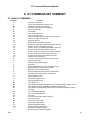
7.3 AT VOICE COMMAND SUMMARY..................................................................................................................... 7-10
7.3.1 Global AT Command Set Extensions ..................................................................................................... 7-10
ATA - Answering in Voice/Audio.......................................................................................................... 7-11
ATD - Dial Command in Voice/Audio................................................................................................... 7-11
ATH - Hang Up in Voice/Audio ............................................................................................................ 7-11
ATZ - Reset from Voice Mode.............................................................................................................7-12
#BDR - Select Baud Rate (Turn off Autobaud) .................................................................................... 7-12
#CID - Enable Caller ID Detection and Select Reporting Format......................................................... 7-12
#CLS - Select Data, Fax, or Voice/Audio............................................................................................. 7-14
#MDL? - Identify Model......................................................................................................... ..............7-14
#MFR? - Identify Manufacturer ...........................................................................................................7-14
#REV? - Identify Revision Level .......................................................................................................... 7-14
7.3.2 AT#V Commands Enabled Only in Voice Mode (#CLS=8) ...................................................................... 7-15
#TL- Audio Output Transmit Level ............................................................................................... .......7-15
#VBQ? - Query Buffer Size...................................................................................................... ...........7-15
#VBS - Bits Per Sample...................................................................................................................... 7-15
#VBT - Beep Tone Timer .................................................................................................................... 7-16
#VCI? - Identify Compression Method............................................................................................ .....7-16
#VLS - Voice Line Select .................................................................................................................... 7-17
#VRA - Ringback Goes Away Timer (Originate) .................................................................................. 7-19
#VRN - Ringback Never Came Timer (Originate) ................................................................................ 7-19
#VRX - Voice Receive ........................................................................................................................ 7-19
#VSD - Enable Silence Deletion (Voice Receive) [ADPCM] ................................................................. 7-20
#VSK - Buffer Skid Setting.................................................................................................................. 7-20
#VSP - Silence Detection Period (Voice Receive) [ADPCM] ................................................................ 7-21
#VSR - Sampling Rate Selection......................................................................................................... 7-21
#VSS - Silence Detection Tuner (Voice Receive) [ADPCM] ................................................................. 7-22
#VTD - DTMF Tone Reporting ............................................................................................................ 7-23
#VTM - Enable Timing Mark Placement .............................................................................................. 7-24
#VTS - Generate Tone Signals (Online Voice Command) ................................................................... 7-24
#VTX - Voice Transmit........................................................................................................................ 7-25
#VGT - Set Playback Volume in the Command State .......................................................................... 7-25
<DLE><u> and <DLE><d> - Set Playback Volume in the Data State................................................... 7-25
7.3.3 Speakerphone Commands .................................................................................................................... 7-25
Originating a Call in Speakerphone Mode ........................................................................................... 7-26
Answering a Call in Speakerphone Mode ............................................................................................ 7-26
Muting the Local Handset During Phone Conversation - Music on Hold............................................... 7-26
Recording a Handset Conversation on the Phone Line........................................................................ 7-27
Recording/Playback from Handset through Sound Chip ...................................................................... 7-27
#SPK Parameter ................................................................................................................................7-27
Room Monitor.....................................................................................................................................7-29
Switching Between #VLS Settings....................................................................................................... 7-29
Reporting of Local Handset Status...................................................................................................... 7-29
7.3.4 Using VoiceView with Speakerphone, Headset, and Handset modes...................................................... 7-30
Using Modem as Dialer Prior to VoiceView Mode................................................................................ 7-31
7.4 S-REGISTERS ...................................................................................................................................................7-32
S30 - Disconnect Inactivity Timer.............................................................................................. ..........7-32
7.5 RESULT CODES FOR VOICE OPERATION....................................................................................................... 7-32
7.6 EXAMPLES OF VOICE OPERATION ................................................................................................................. 7-32
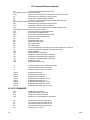
8. AT COMMAND SET SUMMARY ...................................................................................................................................8-1
8.1 BASIC AT COMMANDS........................................................................................................................................8-1
8.2 ECC COMMANDS ................................................................................................................................................8-4
8.3 MNP 10 COMMANDS...........................................................................................................................................8-5
xii
1048
AT Command Reference Manual
8.4 W-CLASS COMMANDS........................................................................................................................................8-5
8.5 CALLER ID COMMANDS .....................................................................................................................................8-5
8.6 FAX CLASS 1 .......................................................................................................................................................8-5
8.7 FAX CLASS 2 .......................................................................................................................................................8-6
8.8 VOICE/AUDIO COMMANDS.................................................................................................................................8-7
8.9 CELLULAR COMMANDS......................................................................................................................................8-7
8.10 AUDIOSPAN AND DSVD COMMANDS ..............................................................................................................8-7
8.11 SYNCHRONOUS ACCESS MODE COMMANDS ................................................................................................8-7
9. COMMON CONFIGURATION SETUP STRINGS ..........................................................................................................9-1
1048
xiii
AT Command Reference Manual
List of Tables
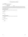
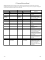
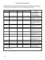
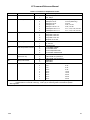
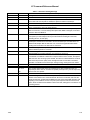
Table 3-1. Result Codes ..................................................................................................................................................3-11
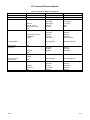
Table 3-2. Remote Modem Configuration and Resulting Transmit Levels ......................................................................... 3-41
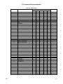
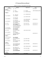
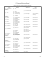
Table 4-1. S-Register Summary.........................................................................................................................................4-2
Table 5-1. Fax Class 1 Commands ....................................................................................................................................5-1
Table 5-2. Fax Class 1 Calling Sequence (One Page)........................................................................................................5-7
Table 5-3. Fax Class 1 Answering Sequence (One Page) ..................................................................................................5-8
Table 6-1. Fax Class 2 Commands ....................................................................................................................................6-2
Table 6-2. T.30 Session Subparameter Codes...................................................................................................................6-7
Table 6-3. T.30 Post Page Message Codes .......................................................................................................................6-8
Table 6-4. T.30 Post Page Response Messages................................................................................................................6-8
Table 6-5. Hang Up Status Codes ...................................................................................................................................6-12
Table 6-6. Send Two Pages, 1-D, No Errors .................................................................................................................... 6-21
Table 6-7. Receive Two Pages, 1-D Data, No Errors........................................................................................................ 6-22
Table 7-1. DTE Speeds .....................................................................................................................................................7-4
Table 7-2. Codes Sent to the DTE ............................................................................................... ......................................7-5
Table 7-3. Shielded DTE Codes.........................................................................................................................................7-7
Table 7-4. AT Voice Commands ......................................................................................................................................7-10
Table 7-5. Device Types Supported by #VLS ................................................................................................................... 7-18
Table 7-6. #VTD Tone Detection/Reporting Bit Settings ................................................................................................... 7-23
Table 7-7. Record a Greeting Message ........................................................................................... ................................ 7-33
Table 7-8. Playback a Greeting Message......................................................................................................................... 7-35
Table 7-9. Answer Call/Play Greeting/Record Message ................................................................................................... 7-36
Table 7-10. Call/Record Message/Receive Fax................................................................................................................ 7-38
Table 7-11. Answer Call, Determine It's a Fax.................................................................................................................. 7-40
Table 7-12. Adaptive Fax/Data/Voice; Determine Data..................................................................................................... 7-41
Table 7-13. Originate a Call, Send Answerer a Message.................................................................................................. 7-42
List of Figures
Figure 6-1. T.30 Session Parameter Relationships........................................................................................................... 6-16
xiv
1048
AT Command Reference Manual
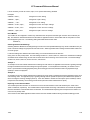
1. INTRODUCTION
1.1 OVERVIEW
This manual describes the AT commands for the following Rockwell modem families:
RC56ACi
RCV56ACFL/SP
RCV56ACF/SP
RCV56ACF/SVD
RC336ACi
RC336ACL
RC336ACFL/SP
RCV336ACi/SP
RCV336ACF/SP
RCV336ACF/SVD
RC288ACi
RC288ACL
RC288ACLW-GSM
RCV288ACi/SP
RC144ACi and RC144ATi
RC144ACL and RC144ATL
RC144ACG
RC144ACF/ATF
RC144ACFL/ATFL
RCV144ACi/SP
RCV144ACF/SP
The descriptions apply to all these modems with any differences between modem product families noted. Refer to Modem
Firmware Release notes for commands applicable to modem firmware.
ATi, ATL, ATF, and ATFL models support error correction and data compression (ECC) performed by the host CPU and
communications software for Windows using the enhanced Rockwell Windows Protocol Interface (RPI or RPI+™) and
WinRPI host software module.
1.1.1 Command Syntax
The fundamental DTE interface command syntax is described in Section 2.
1.1.2 Command Descriptions
These commands are grouped into the following categories:
AT commands
S-Registers
Fax Class 1 commands
Fax Class 2 commands
Voice/Audio commands
AT Command Summary
Section 3
Section 4
Section 5
Section 6
Section 7
Section 8
The AT commands are implemented in microcontroller (MCU) firmware for specific modem models. The support for a
command category is identified by modem model in the modem designer's guide. Additional configuration and
implementation information is available in release notes and/or readme files that accompany MCU firmware release.
1048
1-1
AT Command Reference Manual
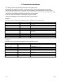
1.1.3 Call Progress and Blacklisting Parameters
The modem MCU firmware may be provided either in reconfigurable form or preconfigured form. Consult the specific
firmware release notes for exact configuration information.
Reconfigurable Form. The modem MCU firmware can be configured for operation in specific countries by the PCcompatible ConfigurACE II program. The call progress and blacklisting parameters described in the ConfigurACE II User's
Manual can be altered and loaded for a number of countries by this program.
Preconfigured Form. Specific MCU firmware configurations may be released that can be directly installed without requiring
the use of ConfigurACE II.
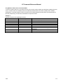
1.1.4 ConfigurACE II for Windows Utility Program
The PC-based ConfigurACE II for Windows utility program allows the OEM to customize the modem firmware to suit specific
application and country requirements. ConfigurACE II for Windows allows programming of functions such as:
Loading of multiple sets of country parameters
Loading of NVRAM factory profiles
Call progress and blacklisting parameters
Entry of S register maximum/minimum values
Limitation of transmit levels
Modification of factory default values
Customization of the ATI4 response
Customization of fax OEM messages
This program modifies the hex object code which can be programmed directly into the system EPROM. Lists of the
generated parameters can be displayed or printed.
Rockwell-provided country parameter files allow a complete set of country-specific call progress and blacklisting parameters
to be selected.
Refer to the ConfigurACE II for Windows software for a detailed description of capabilities and the operating procedure.
1.2 REFERENCE DOCUMENTATION
RC144ACF and RC144ATF Modem Designer's Guide (Order No. 1055)
RC144ACF/ASVD and RCV288ACF/ASVD Modem Designer’s Guide (Order No. 1082)
RC144ACF/SP and RC144ATF Modem Designer's Guide (Order No. 1046)
RC144ACG Modem Designer's Guide (Order No. 1108)
RC144ACi and RC144ACL Modem Designer's Guide (Order No. 876)
RC144ATi and RC144ATL Modem Designer's Guide (Order No. 897)
RC288ACi and RC288ACL Modem Designer's Guide (Order No. 1027)
RC288ACL/SVD SP Modem Designer’s Guide (Order No. 1096)
RCV336ACL Modem Designer’s Guide (Order No. 1121)
RCV56ACF/SP, RCV336ACF/SP, and RC288ACF/SP Modem Designer’s Guide (Order No. 1046)
RCV56ACF/SVD and RCV336ACF/SVD Modem Designer’s Guide (Order No. 1105)
RCV336ACFL/SVD Modem Designer’s Guide (Order No. 1062)
RCV56ACFL/SVD and RCV336ACFL/SVD Modem Designer’s Guide (Order No. 1121)
RCV56ACi and RCV336ACi Modem Designer’s Guide (Order No. 1117)
1-2
1048
AT Command Reference Manual
2. COMMAND SYNTAX
2.1 DTE/DCE INTERCHANGE CIRCUITS
Communication between the DTE and modem is half duplex (i.e., only one entity 'talks' at a time).
2.2 COMMAND SYNTAX AND GUIDELINES
2.2.1 DTE Commands
The ISO 646 character set (CCITT T.50 International Alphabet 5, American Standard Code for Information Interchange) is
used for the issuance of commands and responses. Only the low-order 7 bits of each character are used for commands or
parameters; the high-order bit is ignored. Upper case characters are equivalent to lower case characters.
2.2.2 DTE Command Lines
A command line is a string of characters sent from a DTE to the DCE while the DCE is in a command state. Command lines
have a prefix, a body, and a terminator. The prefix consists of the ASCII characters “AT” (065, 084) or “at” (097, 116). The
body is a string of commands restricted to printable ASCII characters (032 - 126). Space characters (ASCII 032) and control
characters other than carriage return <CR> (default value = ASCII 013 = 0Dh, see register S3), backspace <BS> (default
value = ASCII 008 = 08h, see register S5), and cancel <cntrl-x> (ASCII 024 = 18h) in the command string are ignored. The
default terminator is the <CR> character. Characters that precede the AT prefix are ignored.
2.3 AT COMMAND GUIDELINES
Modem operation is controlled by generic AT commands. These AT commands may be basic AT (i.e., commands preceded
by AT, AT&, AT%, AT*, AT\, AT), AT-, or AT#), S-Register (e.g., S6=n), Fax class 1 (e.g., +FTM), Fax class 2 (e.g.,
+FDCS:), or voice (e.g., #VBS) commands. The command syntax and operation guidelines governing each of these
command categories are described in subsequent sections.
2.3.1 Basic Command Syntax
Characters within the command line are parsed as commands with associated parameter values. The basic commands
consist of single ASCII characters, or single characters preceded by a prefix character, followed by a decimal parameter
(e.g., “&D1"). Missing decimal parameters are evaluated as 0.
2.3.2 Extended Command Syntax
The facsimile commands use extended syntax. They are preceded by the “+F” characters, and they are terminated by the
semicolon “:” character (ASCII 059) or by the <CR> that terminates the command line.
1048
2-1
AT Command Reference Manual
This page is intentionally blank.
2-2
1048
AT Command Reference Manual
3. AT COMMAND SET
3.1 AT COMMAND GUIDELINES
The basic AT commands used to control modem operation are defined in this section. These commands are summarized in
Appendix A. All these commands may not be available in a specific product depending upon supported data rates and
modes. The default values are typical of a fully configured modem supporting all data rates and options. The actual default
value is dependent upon modem firmware as defined by the firmware release notes.
3.1.1 AT Commands, DTE Adaption
Under AT operation, the serial interfaced modem performs an autobaud/autoparity/autolength function on each AT header
entered. The autolength/autoparity facility can detect 7- or 8-bit characters of even, odd, or no parity with one stop bit. This is
not necessary for the parallel interfaced modem since it has direct access to the UART registers.
3.1.2 AT Command Format
A command line is a string of characters sent from a DTE to the modem (DCE) while the modem is in a command state. A
command line has a prefix, a body, and a terminator. Each command line (with the exception of the A/ command) must
begin with the character sequence AT and must be terminated by a carriage return. Commands entered in upper case or
lower case are accepted, but both the A and T must be of the same case, i.e., "AT" = ASCII 065, 084 or “at” = ASCII 097,
116. The body is a string of commands restricted to printable ASCII characters (032 - 126). Space characters (ASCII 032)
and control characters other than CR (ASCII 013) and BS (ASCII 010) in the command string are ignored. The default
terminator is the ASCII <CR> character. Characters that precede the AT prefix are ignored. The command line interpretation
begins upon receipt of the carriage return character.
Characters within the command line are parsed as commands with associated parameter values. The basic commands
consist of single ASCII characters, or single characters preceded by a prefix character (e.g., “&"), followed by a decimal
parameter. Missing decimal parameters are evaluated as 0.
The modem supports the editing of command lines by recognizing a backspace character. When modem echo is enabled,
the modem responds to receipt of a backspace or delete by echoing a backspace character, a space character, and another
backspace. The hex value to be used for the backspace character is programmable through register S5. Values equal to 0
or greater than 127, or the value which corresponds to the carriage return character, cannot be used for the backspace
character. This editing is not applicable to the AT header of a command. A command line may be aborted at any time by
entering < cntrl-x > (18h).
The AT sequence may be followed by any number of commands in sequence, except for commands such as Z, D, or A.
Commands following commands Z, D, or A on the same command line will be ignored. The maximum number of characters
on any command line is 39 (including "A" and "T"). If a syntax error is found anywhere in a command line command, the
remainder of the line will be ignored and the ERROR result code will be returned.
Most commands entered with parameters out of range will not be accepted and the ERROR response will be returned to the
DTE.
Commands will only be accepted by the modem once the previous command has been fully executed, which is normally
indicated by the return of an appropriate result code. Execution of commands D and A, either as a result of a direct
command or a re-execute command, will be aborted if another character is entered before completion of the handshake.
3.1.3 Escape Code Sequence
When the modem has established a connection and has entered on-line data mode, it is possible to break into the data
transmission in order to issue further commands to the modem in an on-line command mode. This is achieved by the DTE
sending to the modem a sequence of three ASCII characters specified by register S2. The default character is '+'. The
maximum time allowed between receipt of the last character of the three escape character sequence from the DTE and
sending of the OK result code to the DTE is controlled by the S12 register.
1048
3-1
AT Command Reference Manual
3.2 AT COMMAND SET
The modem will respond to the commands detailed below. Parameters applicable to each command are listed with the
command description. The defaults shown for each configuration command are those used in the Rockwell factory profile 0.
3.2.1 AT Commands
A/ - Re-execute Command
The modem behaves as though the last command line had been re-sent by the DTE. "A/" will repeat all the commands in the
command buffer.
The principal application of this command is to place another call (using the Dial command) that failed to connect due to a
busy line, no answer, or a wrong number. This command must appear alone on a command line. This command should not
be terminated by a carriage return.
AT= x - Write to Selected S-Register
This command writes the value x to the currently selected S-Register. An S-Register can be selected by using the ATSn
command. All of the S-Registers will return the OK response if x is a number. Some registers may not be written due to
country specific PTT limitations.
Result Codes
OK
For all arguments.
AT? - Read Selected S-Register
This command reads and displays the selected S-Register. An S-Register can be selected by using the ATSn command.
Result Codes:
OK
For all arguments.
A - Answer
The modem will go off-hook and attempt to answer an incoming call if correct conditions are met. Upon successful
completion of answer handshake, the modem will go on-line in answer mode. This command may be affected by the state of
Line Current Sense, if enabled. (Most countries do not require Line Current Sense.) Operation is also dependent upon
+FCLASS command and country-specific requirements.
If +FCLASS=0 is selected, the modem will enter the connect state after exchanging carrier with the remote modem. If no
carrier is detected within a period specified in register S7, the modem hangs up. Any character entered during the connect
sequence will abort the connection attempt.
If +FCLASS=1 or 2 is selected, the modem will go off-hook in V.21 answer mode. It will generate the V.21 2100 Hz answer
tone for 3 ± 0.5 seconds and, following a delay of 70 ms, will proceed as if the +FTH=3 command were issued. At any stage
up to (but excluding) the +FTH=3 command state, any character will abort the communication. (See the description of the
+FTH command for details.)
Bn - CCITT or Bell
When the modem is configured to allow either option, the modem will select Bell or CCITT modulation for a line speed
connection of 300 or 1200 bps according to the parameter supplied. Any other line speed will use a CCITT modulation
standard. The parameter value, if valid, is written to S27 bit 6. (Also, see ATFn command.)
B0
Selects CCITT operation at 300 or 1200 bps during Call Establishment and a subsequent
connection. (Default for W-class models.)
B1
Selects BELL operation at 300 or 1200 bps during Call Establishment and a subsequent
connection. (Default for US models.)
Result Codes:
3-2
OK
n = 0 or 1.
ERROR
Otherwise.
1048
AT Command Reference Manual
Cn - Carrier Control
This command is included for compatibility only, and has no effect other than returning a result code. The only valid
parameter is 1.
Result Codes:
OK
n = 1.
ERROR
Otherwise.
Dn - Dial
This command directs the modem to go on-line, dial according to the string entered and attempt to establish a connection. If
no dial string is supplied, the modem will go on-line and attempt the handshake in originate mode. In W-class models, the
action of going off-hook is affected by the status of the Line Current Sense input, if line current sensing is enabled, and by
the blacklist and delayed list. NOTE: If the ATD command is issued before the S1 register has cleared, the modem will
respond with the NO CARRIER result code.
If +FCLASS=0 is selected, the modem will behave as a data modem and will attempt to connect to another data modem.
The modem will have up to the period of time specified by register S6 or S7 to wait for carrier and complete the handshake.
If this time expires before the modem can complete the handshake, the modem will go on-hook with the NO CARRIER
response. This command will be aborted in progress upon receipt of any DTE character before completion of the handshake.
If +FCLASS=1 or 2 is selected, the modem will behave as a facsimile modem and attempt to connect to a facsimile machine
(or modem) by entering the HDLC V.21 channel 2 receive state (as if +FRH=3 had been issued). This command will be
aborted upon receipt of any DTE character if the modem has not finished dialing. In this case, the modem will go on-hook
and return to command mode after displaying the NO CARRIER message. If the modem has finished dialing, it proceeds as
if the +FRH=3 command has been issued. (Refer to the +FRH command to determine how the modem behaves following
this stage.)
Dial Modifiers. The valid dial string parameters are described below. Punctuation characters may be used for clarity, with
parentheses, hyphen, and spaces being ignored.
1048
0-9
DTMF digits 0 to 9.
*
The 'star' digit (tone dialing only).
#
The 'gate' digit (tone dialing only).
A-D
DTMF digits A, B, C, and D. Some countries may prohibit sending of these digits during dialing.
L
Re-dial last number: the modem will re-dial the last valid telephone number. The L must be
immediately after the D with all the following characters ignored).
P
Select pulse dialing: pulse dial the numbers that follow until a "T" is encountered. Affects current and
subsequent dialing. Some countries prevent changing dialing modes after the first digit is dialed.
T
Select tone dialing: tone dial the numbers that follow until a "P" is encountered. Affects current and
subsequent dialing. Some countries prevent changing dialing modes after the first digit is dialed.
R
This command will be accepted, but not acted on.
S=n
Dial the number stored in the directory (n = 0 to 3). (See &Z.)
!
Flash: the modem will go on-hook for a time defined by the value of S29. Country requirements may
limit the time imposed.
W
Wait for dial tone: the modem will wait for dial tone before dialing the digits following "W". If dial tone
is not detected within the time specified by S7 (US) or S6 (W-class), the modem will abort the rest
of the sequence, return on-hook, and generate an error message.
3-3
AT Command Reference Manual
@
Wait for silence: the modem will wait for at least 5 seconds of silence in the call progress frequency
band before continuing with the next dial string parameter. If the modem does not detect these 5
seconds of silence before the expiration of the call abort timer (S7), the modem will terminate the
call attempt with a NO ANSWER message. If busy detection is enabled, the modem may terminate
the call with the BUSY result code. If answer tone arrives during execution of this parameter, the
modem handshakes.
&
Wait for credit card dialing tone before continuing with the dial string. If the tone is not detected
within the time specified by S7 (US models) or S6 (W-class models), the modem will abort the rest
of the sequence, return on-hook, and generate an error message.
,
Dial pause: the modem will pause for a time specified by S8 before dialing the digits following ",".
;
Return to command state. Added to the end of a dial string, this causes the modem to return to the
command state after it processes the portion of the dial string preceding the ";". This allows the user
to issue additional AT commands while remaining off-hook. The additional AT commands may be
placed in the original command line following the ";" and/or may be entered on subsequent
command lines. The modem will enter call progress only after an additional dial command is issued
without the ";" terminator. Use "H" to abort the dial in progress, and go back on-hook.
^
Toggles calling tone enable/disable: applicable to current dial attempt only.
()
Ignored: may be used to format the dial string.
-
Ignored: may be used to format the dial string.
<space>
Ignored: may be used to format the dial string.
<i>
Invalid character: will be ignored.
>
If enabled by country specific parameter, the modem will generate a grounding pulse on the EARTH
relay output.
En - Command Echo
The modem enables or disables the echo of characters to the DTE according to the parameter supplied. The parameter
value, if valid, is written to S14 bit 1.
E0
Disables command echo.
E1
Enables command echo. (Default.)
Result Codes:
3-4
OK
n = 0 or 1.
ERROR
Otherwise.
1048
AT Command Reference Manual
Fn - Select Line Modulation (RC144 Models Only)
This command selects the line modulation according to the parameter supplied. The line modulation is fixed unless
Automode is selected. This command interacts with the S37 and the N command. The parameter value, if valid, is written to
S37 bits 0-4. To select line modulation, it is recommended that either the F command, or a combination of the S37 and the N
command, be used, but not both.
F0
Selects auto-detect mode. Sets N1 and sets S31 bit 1. In this mode, the modem configures for
automode operation. All connect speeds supported by the modem are possible according to the
remote modem's preference. The contents of S37 are ignored as is the sensed DTE speed.
F1
Selects V.21 or Bell 103 according to the B setting as the only acceptable line speed resulting in a
subsequent connection. Sets N0, sets S37 to 1, and clears S31 bit 1. This command is equivalent
to the command string: ATN0S37=1.
F2
Not supported.
F3
Selects V.23 as the only acceptable line modulation for a subsequent connection. Originator is at
75 bps and answerer is at 1200 bps. Sets N0, sets S37 to 7, and clears S31 bit 1. This command
is equivalent to the command string: ATN0S37=7.
F4
Selects V.22 1200 or Bell 212A according to the B command setting as the only acceptable line
speed for a subsequent connection. Sets N0, sets S37 to 5, and clears S31 bit 1. This command
is equivalent to the command string: ATN0S37=5.
F5
Selects V.22 bis as the only acceptable line modulation for a subsequent connection. Sets N0,
sets S37 to 6, and clears S31 bit 1. This command is equivalent to the command string:
ATN0S37=6.
F6
Select V.32 bis 4800 or V.32 4800 as the only acceptable line modulation for a subsequent
connection. Sets N0, sets S37 to 8, and clears S31 bit 1. This command is equivalent to the
command string: ATN0S37=8.
F7
Selects V.32 bis 7200 as the only acceptable line modulation for a subsequent connection. Sets
N0, sets S37 to 12, and clears S31 bit 1. This command is equivalent to the command string:
ATN0S37=12.
This setting also allows connection at the Rockwell proprietary 7200 V.32 speed, e.g., with a
RC9696/12 based modem.
F8
Selects V.32 bis 9600 or V.32 9600 as the only acceptable line modulations for a subsequent
connection. Sets N0, sets S37 to 9, and clears S31 bit 1. This command is equivalent to the
command string: ATN0S37=9.
F9
Selects V.32 bis 12000 as the only acceptable line modulation for a subsequent connection. Sets
N0, sets S37 to 10, and clears S31 bit 1. This command is equivalent to the command string:
ATN0S37=10.
This setting also allows connection at the Rockwell proprietary 12000 V.32 speed, e.g., with a
RC9696/12 based modem.
F10
1048
Selects V.32 bis 14400 as the only acceptable line modulation for a subsequent connection. Sets
N0, sets S37 to 11, and clears S31 bit 1. This command is equivalent to the command string:
ATN0S37=11.
3-5
AT Command Reference Manual
Hn - Disconnect (Hang-Up)
This command initiates a hang up sequence.
This command may not be available for some countries due to PTT restrictions.
H0
The modem will release the line if the modem is currently on-line, and will terminate any test
(AT&T) that is in progress. Country specific, modulation specific, and error correction protocol
specific (S38) processing is handled outside of the H0 command.
H1
If on-hook, the modem will go off-hook and enter command mode. For US models, the modem
will remain off-hook. For W-class models, the modem will return on-hook after a period of time
determined by S7.
Result Codes:
OK
n = 0 or 1.
ERROR
Otherwise.
In - Identification
The modem reports to the DTE the requested result according to the command parameter.
I0
Reports product code. Example: 28800
I1
Calculates the ROM checksum and reports the least significant byte of the checksum in decimal
(see firmware release notes). Reports 255 if the prestored checksum value is FFh.
I2
Calculates the ROM checksum and compares it with the prestored checksum. Reports "OK" if the
calculated checksum equals the prestored checksum or if the prestored checksum value is FFh;
otherwise reports “ERROR”.
I3
Reports the firmware version (F), basic model (e.g.,V34), application code (A), and interface type
code (I) typically in the form VF.FFF-V34_AI. The application codes are: D = Desktop, L = Low
Power (PCMCIA). The interface type codes are: S = Serial, P = Parallel. Example: V1.400V34_DS
Note: If RPI+ is supported, “ROCKWELL RPI (TM)” is appended.
I4
Reports OEM defined identifier string in either Hayes-compatible binary format (default) or ASCII
format (selectable by ConfigurACE). Example: RC288ACi (ASCII)
I5
Reports Country Code parameter. Example: 022
I6
Reports modem data pump model and internal code revision. Example: RC288DPi Rev 05BA
I7
Reports the DAA code resulting from MCU interrogation of the DAA for auto DAA recognition.
Examples: 000 for US or Canada, 016 for Japan, 033 for Belgium, 034 for Finland, 035 for
France, 037 for Italy, 038 for Netherlands, 039 for Sweden, 040 for Switzerland, and 041 for UK.
Result Codes:
OK
n = 0 to 7.
ERROR
Otherwise.
Ln - Speaker Volume
The modem sets the speaker volume control according to the parameter supplied. The parameter value, if valid, is written to
S22 bits 0 and 1.
L0
Low volume.
L1
Low volume. (Default.)
L2
Medium volume.
L3
High volume.
Result Codes:
3-6
OK
n = 0 to 3.
ERROR
Otherwise.
1048
AT Command Reference Manual
Mn - Speaker Control
This command selects when the speaker will be on or off. The parameter value, if valid, is written to S22 bits 2 and 3.
M0
Speaker is always off.
M1
Speaker is on during call establishment, but off when receiving carrier. (Default.)
M2
Speaker is always on.
M3
Speaker is off when receiving carrier and during dialing, but on during answering.
Result Codes:
OK
n = 0 to 3.
ERROR
Otherwise.
Nn - Automode Enable
This command enables or disables automode detection. The parameter value, if valid, is written to S31 bit 1.
N0
Automode detection is disabled (equivalent to setting the +MS <automode> subparameter to 0). A
subsequent handshake will be conducted according to the contents of S37 or, if S37 is zero,
according to the most recently sensed DTE speed.
N1
Automode detection is enabled (equivalent to setting the +MS <automode> subparameter to 1). A
subsequent handshake will be conducted according the automode algorithm supported by the
modem, e.g., according to the contents of S37 or, if S37 is zero, starting at 28800 bps V.34
(RC288). This command is also equivalent to F0 (RC144). (Default.)
Result Codes:
OK
n = 0 or 1.
ERROR
Otherwise.
Notes:
1.
The Nn and S37=x commands override the +MS command settings. When the N0 or N1 command is issued, the +MS
subparameters are updated to reflect the Nn and S37 values (see +MS command and S37 register). For example:
N1S37=10 updates the +MS command subparameters to reflect +MS=10,1,300,12000
N0S37=10 updates the +MS command subparameters to reflect +MS=10,0,12000,12000
2.
Use of the +MS command is recommended instead of the Nn and S37=x commands. Nn and S37=x commands are
supported for compatibility with existing communication software.
On - Return to On-Line Data Mode
This command determines how the modem will enter the on-line data mode. If the modem is in the on-line command mode,
the enters the on-line data mode with or without a retrain. If the modem is in the off-line command mode (no connection),
ERROR is reported.
O0
Enters on-line data mode without a retrain. Handling is determined by the Call Establishment task.
Generally, if a connection exists, this command connects the DTE back to the remote modem
after an escape (+++).
O1
Enters on-line data mode with a retrain before returning to on-line data mode.
Result Codes:
1048
OK
n = 0 or 1 and a connection exists.
ERROR
Otherwise or if not connected.
3-7
AT Command Reference Manual
P - Set Pulse Dial Default
This command forces pulse dialing until the next T dial modifier or T command is received. Sets S14 bit 5.
As soon as a dial command is executed which explicitly specifies the dialing mode for that particular call (e.g., ATDT...), this
command is overridden so that all future dialing will be tone dialed. (See T command.)
This command may not be permitted in some countries.
Result Code:
OK
Qn - Quiet Results Codes Control
The command enables or disables the sending of result codes to the DTE according to the parameter supplied. The
parameter value, if valid, is written to S14 bit 2.
Q0
Enables result codes to the DTE. (Default.)
Q1
Disables result codes to the DTE.
Result Codes:
OK
n = 0 or 1.
ERROR
Otherwise.
Sn - Read/Write S-Register
The modem selects an S-Register, performs an S-Register read or write function, or reports the value of an S-Register.
n
Establishes S-Register n as the last register accessed.
n=v
Sets S-Register n to the value v.
n?
Reports the value of S-Register n.
The parameter n can be omitted, in which case the last S-Register accessed will be assumed. The S can be omitted for AT=
and AT?, in which case the last S-Register accessed will be assumed.
For example:
ATS7 establishes S7 as the last accessed register.
AT=40 sets the contents of the last register accessed to 40.
ATS=20 sets the contents of the last register accessed to 20.
If the number "n" is beyond the range of the S-Registers available, the modem will return the ERROR message. The value
"v" is "MOD"ed with 256. If the result is outside the range permitted for a given S-Register the values will still be stored, but
functionally the lower and higher limits will be observed. Input and output are always in decimal format. Note that some SRegisters are read-only.
In some cases, writing to the S-Register will appear to be accepted but the value will not actually be written.
Due to country restrictions, some commands will be accepted, but the value may be limited and replaced by a maximum or
minimum value.
Minimum, maximum, and default values for S-Registers may be altered with ConfigurACE.
3-8
1048
AT Command Reference Manual
T - Set Tone Dial Default
This command forces DTMF dialing until the next P dial modifier or P command is received. The modem will set an SRegister bit to indicate that all subsequent dialing should be conducted in tone mode. Note that the DP command will
override this command. Clears S14 bit 5.
This command may not be permitted in some countries. (See P.)
Result Code:
OK
Vn - Result Code Form
This command selects the sending of short-form or long-form result codes to the DTE. The parameter, if valid, is written to
S14 bit 3.
V0
Enables short-form (terse) result codes. Line feed is not issued before a short-form result code.
V1
Enables long-form (verbose) result codes. (Default.)
Result Codes:
OK
n = 0 or 1.
ERROR
Otherwise.
Wn - Connect Message Control
This command controls the format of CONNECT messages. The parameter value, if valid, is written to S31 bits 2 and 3.
Note that the Wn command can be overridden by register S95 bits (see S95 description).
W0
Upon connection, the modem reports only the DTE speed (e.g., CONNECT 19200). Subsequent
responses are disabled. (Default.)
W1
Upon connection, the modem reports the line speed, the error correction protocol, and the DTE
speed, respectively. Subsequent responses are disabled.
W2
Upon connection, the modem reports the DCE speed (e.g., CONNECT 14400). Subsequent
responses are disabled.
Result Codes:
1048
OK
n = 0, 1, or 2.
ERROR
Otherwise.
3-9
AT Command Reference Manual
Xn - Extended Result Codes
This command selects which subset of the result messages will be used by the modem to inform the DTE of the results of
commands.
Blind dialing is enabled or disabled by country parameters. If the user wishes to enforce dial tone detection, a "W" can be
placed in the dial string (see D command). Note that the information below is based upon the default implementation of the X
results table. Table 3-1 indicates the messages which are enabled for each X value.
If the modem is in facsimile mode (+FCLASS=1 or 2), the only message sent to indicate a connection is CONNECT without
a speed indication.
X0
Disables monitoring of busy tones unless forced otherwise by country requirements; send only
OK, CONNECT, RING, NO CARRIER, ERROR, and NO ANSWER result codes. Blind dialing is
enabled/disabled by country parameters. If busy tone detection is enforced and busy tone is
detected, NO CARRIER will be reported. If dial tone detection is enforced or selected and dial
tone is not detected, NO CARRIER will be reported instead of NO DIAL TONE. The value 000b is
written to S22 bits 6, 5, and 4, respectively.
X1
Disables monitoring of busy tones unless forced otherwise by country requirements; send only
OK, CONNECT, RING, NO CARRIER, ERROR, NO ANSWER, and CONNECT XXXX (XXXX =
rate). Blind dialing enabled/disabled by country parameters. If busy tone detection is enforced and
busy tone is detected, NO CARRIER will be reported instead of BUSY. If dial tone detection is
enforced or selected and dial tone is not detected, NO CARRIER will be reported instead of NO
DIAL TONE. The value 100b is written to S22 bits 6, 5, and 4, respectively.
X2
Disables monitoring of busy tones unless forced otherwise by country requirements; send only
OK, CONNECT, RING, NO CARRIER, ERROR, NO DIALTONE, NO ANSWER, and CONNECT
XXXX. If busy tone detection is enforced and busy tone is detected, NO CARRIER will be
reported instead of BUSY. If dial tone detection is enforced or selected and dial tone is not
detected, NO DIAL TONE will be reported instead of NO CARRIER. The value 101b is written to
S22 bits 6, 5, and 4, respectively.
X3
Enables monitoring of busy tones; send only OK, CONNECT, RING, NO CARRIER, ERROR, NO
ANSWER, and CONNECT XXXX. Blind dialing is enabled/disabled by country parameters. If dial
tone detection is enforced and dial tone is not detected, NO CARRIER will be reported. The value
110b is written to S22 bits 6, 5, and 4, respectively.
X4
Enables monitoring of busy tones; send all messages. The value 111b is written to S22 bits 6, 5,
and 4, respectively. (Default.)
Result Codes:
3-10
OK
n = 0 to 4.
ERROR
Otherwise.
1048
AT Command Reference Manual
Table 3-1. Result Codes
Short Form
Long Form
n Value in ATXn Command
0
1048
1
2
3
Notes
4
0
OK
x
x
x
x
x
1
CONNECT
x
x
x
x
x
2
RING
x
x
x
x
x
3
NO CARRIER
x
x
x
x
x
4
ERROR
x
x
x
x
x
5
CONNECT 1200
1
x
x
x
x
6
NO DIALTONE
3
3
x
x
x
7
BUSY
3
3
3
x
x
8
NO ANSWER
x
x
x
x
x
9
CONNECT 0600
1
x
x
x
x
10
CONNECT 2400
1
x
x
x
x
11
CONNECT 4800
1
x
x
x
x
12
CONNECT 9600
1
x
x
x
x
13
CONNECT 7200
1
x
x
x
x
14
CONNECT 12000
1
x
x
x
x
15
CONNECT 14400
1
x
x
x
x
16
CONNECT 19200
1
x
x
x
x
17
CONNECT 38400
1
x
x
x
x
18
CONNECT 57600
1
x
x
x
x
19
CONNECT 115200
1
x
x
x
x
20
CONNECT 230400
x
x
x
x
x
22
CONNECT 75TX/1200RX
1
x
x
x
x
23
CONNECT 1200TX/75RX
1
x
x
x
x
24
DELAYED
4
4
4
4
x
32
BLACKLISTED
4
4
4
4
x
33
FAX
x
x
x
x
x
35
DATA
x
x
x
x
x
40
CARRIER 300
x
x
x
x
x
44
CARRIER 1200/75
x
x
x
x
x
45
CARRIER 75/1200
x
x
x
x
x
46
CARRIER 1200
x
x
x
x
x
47
CARRIER 2400
x
x
x
x
x
48
CARRIER 4800
x
x
x
x
x
49
CARRIER 7200
x
x
x
x
x
50
CARRIER 9600
x
x
x
x
x
51
CARRIER 12000
x
x
x
x
x
52
CARRIER 14400
x
x
x
x
x
53
CARRIER 16800
x
x
x
x
x
Note 2
54
CARRIER 19200
x
x
x
x
x
Note 2
55
CARRIER 21600
x
x
x
x
x
Note 2
56
CARRIER 24000
x
x
x
x
x
Note 2
57
CARRIER 26400
x
x
x
x
x
Note 2
58
CARRIER 28800
x
x
x
x
x
Note 2
59
CONNECT 16800
1
x
x
x
x
Note 2
61
CONNECT 21600
1
x
x
x
x
Note 2
62
CONNECT 24000
1
x
x
x
x
Note 2
Note 4
3-11
AT Command Reference Manual
Table 3-1. Result Codes (Cont'd)
Short Form
Long Form
n Value in ATXn Command
Notes
0
1
2
3
4
63
CONNECT 26400
1
x
x
x
x
Note 2
64
CONNECT 28800
1
x
x
x
x
Note 2
66
COMPRESSION: CLASS 5
x
x
x
x
x
67
COMPRESSION: V.42 bis
x
x
x
x
x
69
COMPRESSION: NONE
x
x
x
x
x
70
PROTOCOL: NONE
x
x
x
x
x
77
PROTOCOL: LAPM
x
x
x
x
x
78
CARRIER 31200
x
x
x
x
x
Note 3
79
CARRIER 33600
x
x
x
x
x
Note 3
80
PROTOCOL: ALT
x
x
x
x
x
81
PROTOCOL: ALT-CELLULAR
x
x
x
x
x
84
CONNECT 33600
1
x
x
x
x
91
CONNECT 31200
1
x
x
x
x
Note 3
150
CARRIER 32000
x
x
x
x
x
Note 4
151
CARRIER 34000
x
x
x
x
x
Note 4
152
CARRIER 36000
x
x
x
x
x
Note 4
153
CARRIER 38000
x
x
x
x
x
Note 4
154
CARRIER 40000
x
x
x
x
x
Note 4
155
CARRIER 42000
x
x
x
x
x
Note 4
156
CARRIER 44000
x
x
x
x
x
Note 4
157
CARRIER 46000
x
x
x
x
x
Note 4
158
CARRIER 48000
x
x
x
x
x
Note 4
159
CARRIER 50000
x
x
x
x
x
Note 4
160
CARRIER 52000
x
x
x
x
x
Note 4
161
CARRIER 54000
x
x
x
x
x
Note 4
162
CARRIER 56000
x
x
x
x
x
Note 4
165
CONNECT 32000
x
x
x
x
x
Note 4
166
CONNECT 34000
x
x
x
x
x
Note 4
167
CONNECT 36000
x
x
x
x
x
Note 4
168
CONNECT 38000
x
x
x
x
x
Note 4
169
CONNECT 40000
x
x
x
x
x
Note 4
170
CONNECT 42000
x
x
x
x
x
Note 4
171
CONNECT 44000
x
x
x
x
x
Note 4
172
CONNECT 46000
x
x
x
x
x
Note 4
173
CONNECT 48000
x
x
x
x
x
Note 4
174
CONNECT 50000
x
x
x
x
x
Note 4
175
CONNECT 52000
x
x
x
x
x
Note 4
176
CONNECT 54000
x
x
x
x
x
Note 4
177
CONNECT 56000
x
x
x
x
x
Note 4
+F4
+FCERROR
x
x
x
x
x
Note 3
Notes:
1.
2.
3.
4.
3-12
An 'x' in a column indicates that the message (either the long form if verbose, or the value only for short form) will be
generated when that particular value of 'n' (shown at the top of the column) has been selected by the use of ATXn. If the
column is blank, then no message will be generated for that x option. A numeral indicates which less explicit message
(verbose or short form) will be output for that X option. (Also, see Section 3.3).
RC288 and higher rate modems.
RC336 and higher rate modems.
RC56 modems.
1048
AT Command Reference Manual
Yn - Long Space Disconnect
This command enables/disables the generation and response to long space disconnect. The parameter value, if valid, is
written to S21 bit 7.
Y0
Disables long space disconnect. (default.)
Y1
Enables long space disconnect. In non-error correction mode, the modem will send a long space
of four seconds prior to going on-hook. In non-error correction mode, the modem will respond to
the receipt of a long space (i.e., a break signal greater than 1.6 seconds) by going on-hook.
Result Codes:
OK
n = 0 or 1.
ERROR
Otherwise.
Zn - Soft Reset and Restore Profile
The modem performs a soft reset and restores (recalls) the configuration profile according to the parameter supplied. If no
parameter is specified, zero is assumed.
Z0
Soft reset and restore stored profile 0.
Z1
Soft reset and restore stored profile 1.
Result Codes:
1048
OK
n = 0 or 1.
ERROR
Otherwise.
3-13
AT Command Reference Manual
3.2.2 AT& Commands
&Cn - RLSD (DCD) Option
The modem controls the RLSD output in accordance with the parameter supplied. The parameter value, if valid, is written to
S21 bit 5.
&C0
RLSD remains ON at all times.
&C1
RLSD follows the state of the carrier. (Default.)
Result Codes:
OK
n = 0 or 1.
ERROR
Otherwise.
&Dn - DTR Option
This command interprets the ON to OFF transition of the DTR signal from the DTE in accordance with the parameter
supplied. The parameter value, if valid, is written to S21 bits 3 and 4. Also, see S25.
&D0 -
&D1
DTR drop is interpreted according to the current &Qn setting as follows:
&Q0, &Q5, &Q6
DTR is ignored (assumed ON). Allows operation with DTEs which do
not provide DTR.
&Q1, &Q4
DTR drop causes the modem to hang up. Auto-answer is not affected.
&Q2, &Q3
DTR drop causes the modem to hang up. Auto-answer is inhibited.
DTR drop is interpreted according to the current &Qn setting as follows:
&Q0, &Q1, &Q4, &Q5, &Q6
DTR drop is interpreted by the modem as if the asynchronous
escape sequence had been entered. The modem returns to
asynchronous command state without disconnecting.
&Q2, &Q3
&D2
DTR drop is interpreted according to the current &Qn setting as follows:
&Q0 through &Q6
&D3
DTR drop causes the modem to hang up. Auto-answer is inhibited.
DTR drop causes the modem to hang up. Auto-answer is inhibited.
(Default.)
DTR drop is interpreted according to the current &Qn setting as follows:
&Q0, &Q1, &Q4, &Q5, &Q6
DTR drop causes the modem to perform a soft reset as if the
Z command were received. The &Y setting determines which profile is
loaded.
&Q2, &Q3
DTR drop causes the modem to hang up. Auto-answer is inhibited.
If &Q5, &Q6, +FCLASS=1 or +FCLASS=2 is in effect, the action taken is the same as for &Q0.
&Fn - Restore Factory Configuration (Profile)
The modem loads the factory default configuration (profile). The factory defaults are identified for each command and in the
S-Register descriptions. A configuration (profile) consists of a subset of S-Registers.
&F0
Restore factory configuration 0.
&F1
Restore factory configuration 1.
Result Codes:
OK
ERROR
3-14
If the modem is connected.
1048
AT Command Reference Manual
&Gn - Select Guard Tone
The modem generates the guard tone selected by this command according to the parameter supplied (DPSK modulation
modes only). The parameter value, if valid, is written to S23 bits 6 and 7.
&G0
Disables guard tone. (Default for US models.)
&G1
Disables guard tone.
&G2
Selects 1800 Hz guard tone. (Default for W-class models.)
This command may not be permitted in some countries.
Result Codes:
OK
n = 0 to 2.
ERROR
Otherwise.
&Jn - Telephone Jack Control
This command is included only for compatibility and performs no function except to load the S-Register. The parameter
value, if valid, is written S21 bit 1.
&J0
&J0 command. (Default.)
&J1
&J1 command.
Result Codes:
OK
n = 0 or 1.
ERROR
Otherwise.
&Kn - Flow Control
This command defines the DTE/DCE (terminal/modem) flow control mechanism. The parameter value, if valid, is written to
S39 bits 0, 1, and 2.
&K0
Disables flow control.
&K3
Enables RTS/CTS flow control. (Default for data modem modes.)
&K4
Enables XON/XOFF flow control.
&K5
Enables transparent XON/XOFF flow control.
&K6
Enables both RTS/CTS and XON/XOFF flow control. (Default for fax modem and voice modes.)
Result Codes:
OK
n = 0, 3, 4, 5, or 6.
ERROR
Otherwise.
&Ln - Leased Line Operation
This command requests leased line or dial-up operation. This command is provided for compatibility only; no mode change is
performed, dial-up operation continues. The OK response is returned for a valid parameter, but no other action is performed.
The parameter value, if valid, is written to S27 bit 2.
&L0
Requests dial-up operation. Dial-up operation continues.
Result Codes:
1048
OK
n = 0.
ERROR
Otherwise.
3-15
AT Command Reference Manual
&Mn - Asynchronous/Synchronous Mode Selection
This command determines the DTR operating mode. The modem treats the &M command as a subset of the &Q command.
&M0
Selects direct asynchronous operation. Note that the command sequence &M0\N0 selects normal
buffered mode, but the command sequence \N0&M0 selects direct mode. This is because the \N0
command is analogous to the &Q6 command. The value 000b is written to S27 bits 3, 1, and 0,
respectively. (See &Q).
&M1
Selects synchronous connect mode with async off-line command mode. The value 001b is written
to S27 bits 3, 1, and 0, respectively. (Serial interface operation only.)
&M2
Selects synchronous connect mode with async off-line command mode. Same as &M1 except
that &M2 enables DTR dialing of directory slot 0. The modem will disconnect if DTR is OFF for
more than the period in S25 (in units of hundredths of a second): the data connection will be
synchronous. The value 010b is written to S27 bits 3, 1, and 0, respectively. (Serial interface
operation only.)
&M3
Selects synchronous connect mode. This mode allows DTR to act as a talk/data switch. The call
is manually initiated while DTR is inactive. When DTR becomes active, the handshake proceeds
in originate or answer mode according to S14 bit 7. The value 011b is written to S27 bits 3, 1, and
0, respectively. (Serial interface operation only.)
Result Codes:
OK
n = 0 to 3.
ERROR
Otherwise.
&Pn - Select Pulse Dial Make/Break Ratio
This command determines the make/break ratio used during pulse dialing. It is only effective if the appropriate bit to enable
this command is set through the ConfigurACE program. If enabled, it will override the make/break ratios in the OEM
parameters in ConfigurACE. The default is country-dependent. The parameter value, if valid, is written to S28 bits 3 and 4.
&P0
Selects 39%-61% make/break ratio at 10 pulses per second. (Default.)
&P1
Selects 33%-67% make/break ratio at 10 pulses per second.
&P2
Selects 39%-61% make/break ratio at 20 pulses per second.
&P3
Selects 33%-67% make/break ratio at 20 pulses per second.
Result Codes:
3-16
OK
n = 0 to 3.
ERROR
Otherwise.
1048
AT Command Reference Manual
&Qn - Sync/Async Mode
This command is an extension of the &M command and is used to control the connection modes permitted. It is used in
conjunction with S36 and S48. (Also, see \N.)
NOTE: When the &Q0 to &Q4 command is issued to select the mode, the subsequent connect message will report the DCE
speed regardless of the W command and S95 settings.
&Q0
Selects direct asynchronous operation. The value 000b is written to S27 bits 3, 1, and 0,
respectively. See &M0.
&Q1
Selects synchronous connect mode with async off-line command mode. The value 001b is written
to S27 bits 3, 1, and 0, respectively. See &M1. (Serial interface operation only.)
&Q2
Selects synchronous connect mode with async off-line command mode and enables DTR dialing
of directory 0. The value 010b is written to S27 bits 3, 1, and 0, respectively. See &M2. (Serial
interface operation only.)
&Q3
Selects synchronous connect mode with async off-line command mode and enables DTR to act
as Talk/Data switch. The value 011b is written to S27 bits 3, 1, and 0, respectively. See &M3.
(Serial interface operation only.)
&Q4
Selects AutoSync operation. The value 100b is written to S27 bits 3, 1, and 0, respectively.
AutoSync operation, when used in conjunction with the Hayes Synchronous Interface (HSI)
capability in the DTE, provides synchronous communication capability from an asynchronous
terminal.
Starting AutoSync. Set registers S19, S20, and S25 to the desired values before selecting
AutoSync operation with &Q4. After the CONNECT message is issued, the modem waits the
period of time specified by S25 before examining DTR. If DTR is on, the modem enters the
synchronous operating state; if DTR is off, the modem terminates the line connection and returns
to the asynchronous command state.
Stopping AutoSync. AutoSync operation is stopped upon loss of carrier or the on-to-off
transition of DTR. Loss of carrier will cause the modem to return to the asynchronous command
state. An on-to-off transition of DTR will cause the modem to return to the asynchronous
command state and either not terminate the line connection (&D1 active) or terminate the line
connection (any other &Dn command active).
&Q5
The modem will try to negotiate an error-corrected link. The modem can be configured using S36
to determine whether a failure will result in the modem returning on-hook or will result in fallback
to an asynchronous connection. The value 101b is written to S27 bits 3, 1, and 0, respectively.
(Default.)
&Q6
Selects asynchronous operation in normal mode (speed buffering). The value 110b is written to
S27 bits 3, 1, and 0, respectively.
Result Codes:
1048
OK
n = 0 to 6.
ERROR
Otherwise.
3-17
AT Command Reference Manual
&Rn - RTS/CTS Option
This selects how the modem controls CTS. CTS operation is modified if hardware flow control is selected (see &K
command). The parameter value, if valid, is written to S21 bit 2.
&R0
In sync mode, CTS tracks the state of RTS; the RTS-to-CTS delay is defined by S26. In async
mode, CTS is normally ON and will turn OFF only if required by flow control.
&R1
In sync mode, CTS is always ON (RTS transitions are ignored). tracks the state of RTS; In async
mode, CTS is normally ON and will turn OFF only if required by flow control.
Result Codes:
OK
n = 0 or 1.
ERROR
Otherwise.
&Sn - DSR Override
This command selects how the modem will control DSR. The parameter value, if valid, is written to S21 bit 6.
&S0
DSR will remain ON at all times. (Default.)
&S1
DSR will become active after answer tone has been detected and inactive after the carrier has
been lost.
Result Codes:
OK
n = 0 or 1.
ERROR
Otherwise.
&Tn - Test and Diagnostics
The modem will perform selected test and diagnostic functions according to the parameter supplied. A test can be run only
when in an asynchronous operation in non-error-correction mode (normal or direct mode). To terminate a test in progress,
the escape sequence must be entered first, except for parameters 7 and 8 (see Section 3.1.3). If S18 is non-zero, a test will
terminate automatically after the time specified by S18 and display the OK message. Note: For tests 3, 6, and 7, a
connection between the two modems must first be established.
3-18
&T0
Terminates test in progress. Clears S16.
&T1
Initiates local analog loopback, V.54 Loop 3. Sets S16 bit 0. If a connection exists when this
command is issued, the modem hangs up. The CONNECT XXXX message is displayed upon the
start of the test.
&T2
Returns ERROR.
&T3
Initiates local digital loopback, V.54 Loop 2. Sets S16 bit 2. If no connection exists, ERROR is
returned. Sets S16 bit 4 when the test is in progress.
&T4
Enables digital loopback acknowledgment for remote request, i.e., an RDL request from a remote
modem is allowed. Sets S23 bit 0.
&T5
Disables digital loopback acknowledgment for remote request, i.e., an RDL request from a remote
modem is denied. Clears S23 bit 0. (Default.)
&T6
Requests a remote digital loopback (RDL), V.54 Loop 2, without self test. If no connection exists,
ERROR is returned. Sets S16 bit 4 when the test is in progress. The CONNECT XXXX message
is displayed upon the start of the test.
&T7
Requests a remote digital loopback (RDL),V.54 Loop 2, with self test. (In self test, a test pattern is
looped back and checked by the modem.) If no connection exists, ERROR is returned. When the
test is terminated either via expiration of S18, or via the &T0 or H command, the number of
detected errors is reported to the DTE. Sets S16 bit 5 when the test is in progress.
&T8
Initiates local analog loopback, V.54 Loop 3, with self test. (In self test, a test pattern is looped
back and checked by the modem.) If a connection exists, the modem hangs up before the test is
initiated. When the test is terminated either via expiration of S18, or via the &T0 or H command,
the number of detected errors is reported to the DTE. Sets S16 bit 6 when the test is in progress.
This command may not be available in some countries due to PTT restrictions.
1048
AT Command Reference Manual
&V - Display Current Configuration and Stored Profiles
Reports the current (active) configuration, the stored (user) profiles, and the first four stored telephone numbers. The stored
profiles and telephone numbers are not displayed if the NVRAM is not installed or is not operational as detected by the
NVRAM test during reset processing.
Result Code:
OK
Example:
AT&V
ACTIVE PROFILE:
B0 E1 L1 M1 N1 QO T V1 W0 X4 Y0 &C0 &D0 &G2 &J0 &K3 &Q5 &R1 &S0 &T4 &X0 &Y0
S00:002 S01:000 S02:043 S03:013 S04:010 S05:008 S06:002 S07:030 S08:002 S09:006
S10:014 S11:255 S12:050 S18:000 S25:005 S26:001 S36:007 S37:000 S38:020 S46:138
S48:007 S95:000
STORED PROFILE 0:
B0 E1 L1 M1 N1 QO T V1 W0 X4 Y0 &C0 &D0 &G2 &J0 &K3 &Q5 &R1 &S0 &T4 &X0
S00:002 S02:043 S06:002 S07:030 S08:002 S09:006 S10:014 S11:095 S12:050 S18:000
S36:007 S37:000 S40:105 S41:003 S46:138 S95:000
STORED PROFILE 1:
B0 E1 L1 M1 N1 QO T V1 W0 X4 Y0 &C0 &D0 &G2 &J0 &K3 &Q5 &R1 &S0 &T4 &X0
S00:002 S02:043 S06:002 S07:030 S08:002 S09:006 S10:014 S11:095 S12:050 S18:000
S36:007 S37:000 S40:105 S41:003 S46:138 S95:000
TELEPHONE NUMBERS:
0 =
1 =
2 =
3 =
OK
3.2.3 &V1 - Display Last Connection Statistics
Displays the last connection statistics in the following format (shown with typical results):
TERMINATION REASON.......... LINK DISCONNECT or LOCAL REQUEST
LAST TX data rate........... 33600 BPS
HIGHEST TX data rate........ 33600 BPS
LAST RX data rate........... 28800 BPS
HIGHEST RX data rate........ 28800 BPS
Error correction PROTOCOL... LAPM
Data COMPRESSION............ V42Bis
Line QUALITY................ 030
Highest SPX RX state........ 068
Highest SPX TX state........ 067
1048
3-19
AT Command Reference Manual
&Wn - Store Current Configuration
Saves the current (active) configuration (profile), including S-Registers, in one of the two user profiles in NVRAM as denoted
by the parameter value. This command will yield an ERROR message if the NVRAM is not installed or is not operational as
detected by the NVRAM test.
The current configuration is comprised of a list of storable parameters illustrated in the &V command. These settings are
restored to the active configuration upon receiving an Zn command or at power up (see &Yn command).
&W0
Store the current configuration as profile 0.
&W1
Store the current configuration as profile 1.
Result Codes:
OK
n = 0 or 1.
ERROR
Otherwise.
&Xn - Select Synchronous Clock Source
Selects the source of the transmit clock for the synchronous mode of operation. The parameter value, if valid, is written to
S27 bits 4 and 5.
In asynchronous mode, the transmit and receive clocks are turned OFF. In synchronous mode, the clocks are turned ON
with the frequency of 1200 Hz or faster corresponding to the speed that is selected for modem operation.
&X0
Selects internal timing. The modem generates the transmit clock signal and applies it to the
TXCLK output at the serial interface.
&X1
Selects external timing. The local DTE sources the transmit clock signal on the XTCLK input of
the serial interface. The modem applies this clock to the TXCLK output at the serial interface.
&X2
Selects slave receive timing. The modem derives the transmit clock signal from the incoming
carrier and applies it to the TXCLK output at the serial interface.
Result Codes:
OK
n = 0 to 2.
ERROR
Otherwise.
&Yn - Designate a Default Reset Profile
Selects which user profile will be used after a hard reset.
&Y0
The modem will use profile 0.
&Y1
The modem will use profile 1.
Result Codes:
OK
n = 0 to 1.
ERROR
If n > 1, or if NVRAM is not installed or is not operational.
&Zn=x - Store Telephone Number
The modem can store up to four telephone numbers and each telephone number dial string can contain up to 34 digits.
&Zn=x
n = 0 to 3 and x = dial string. (Requires 256-byte NVRAM.)
Result Codes:
3-20
OK
For n ≤ 3, and x ≤ 34 digits.
ERROR
If n > 3, x > 35 digits, or if NVRAM is not installed or is not operational.
1048
AT Command Reference Manual
3.2.4 AT% Commands
%En - Enable/Disable Line Quality Monitor and Auto-Retrain or Fallback/Fall Forward
Controls whether or not the modem will automatically monitor the line quality and request a retrain (%E1) or fall back when
line quality is insufficient or fall forward when line quality is sufficient (%E2). The parameter value, if valid, is written to S41
bits 2 and 6.
If enabled, the modem attempts to retrain for a maximum of 30 seconds.
%E0
Disable line quality monitor and auto-retrain.
%E1
Enable line quality monitor and auto-retrain.
%E2
Enable line quality monitor and fallback/fall forward. (Default.)
Result Codes:
OK
n = 0, 1, or 2.
ERROR
Otherwise.
Fallback/Fall Forward. When %E2 is active, the modem monitors the line quality (EQM). When line quality is insufficient,
the modem will initiate a rate renegotiation to a lower speed within the V.34/V.32 bis/V.32 (RC288) or V.32 bis/V.32 (RC144)
modulation speeds. The modem will keep falling back within the current modulation if necessary until the speed reaches
2400 bps (V.34) or 4800 bps (V.32). Below this rate, the modem will only do retrains if EQM thresholds are exceeded. If the
EQM is sufficient for at least one minute, the modem will initiate a rate renegotiation to a higher speed within the current
modulation speeds. The rate renegotiations will be done without a retrain if a V.32 bis connection is established.
Speeds attempted during fallback/fall forward are those shown to be available in the rate sequences exchanged during the
initial connection. Fallback/fall forward is available in error correction and normal modes, but not in direct mode or
synchronous mode with external clocks.
%L - Line Signal Level
Returns a value which indicates the received signal level. The value returned is a direct indication (DAA dependent) of the
receive level at the MDP, not at the telephone line connector. For example, 009 = -9 dBm, 043 = -43 dBm, and so on.
Result Codes:
OK
%Q - Line Signal Quality
Reports the line signal quality (DAA dependent). Returns the higher order byte of the EQM value. Based on the EQM value,
retrain or fallback/fall forward may be initiated if enabled by %E1 or %E2.
Example:
AT%Q
015
Result Codes:
1048
OK
If connected.
ERROR
If not connected, or connected in 300 bps, V.23, or fax modes.
3-21
AT Command Reference Manual
%7 - Plug and Play Serial Number
%7<8 hex numbers><same 8 hex numbers><cr> - Sets Plug and Play Serial Number
Sets and stores eight serial numbers in hex format used for serial Plug and Play and for ISA Plug and Play which use the
Rockwell 11575 Plug and Play device.
Example:
AT%7<8 hex numbers><same 8 hex numbers>
Result Codes:
OK
<8 hex numbers><same 8 hex numbers>
ERROR
Otherwise
To display the stored serial number, issue AT"?<cr>.
%8 - Plug and Play Vendor ID and Product Number
Sets and stores Vendor ID and product number for serial Plug and Play and for ISA Plug and Play which use the Rockwell
11575 Plug and Play device.
Example:
AT%8<3 ASCII characters><4 hex numbers><same 3 ASCII characters><same 4 hex numbers><cr>
Result Codes:
3-22
OK
<3 ASCII characters><4 hex numbers><same 3 ASCII characters><same 4 hex numbers>
ERROR
Otherwise
1048
AT Command Reference Manual
3.2.5 AT\ Commands
\Kn - Break Control
Controls the response of the modem to a break received from the DTE or the remote modem or the \B command according
to the parameter supplied. The parameter value, if valid, is written to S40 bits 3, 4, and 5.
The response is different in three separate states.
The first state is where the modem receives a break from the DTE when the modem is operating in data transfer mode:
\K0
Enter on-line command mode, no break sent to the remote modem.
\K1
Clear data buffers and send break to remote modem.
\K2
Same as 0.
\K3
Send break to remote modem immediately.
\K4
Same as 0.
\K5
Send break to remote modem in sequence with transmitted data. (Default.)
The second case is where the modem is in the on-line command state (waiting for AT commands) during a data connection,
and the \B is received in order to send a break to the remote modem:
\K0
Clear data buffers and send break to remote modem.
\K1
Clear data buffers and send break to remote modem. (Same as 0.)
\K2
Send break to remote modem immediately.
\K3
Send break to remote modem immediately. (Same as 2.)
\K4
Send break to remote modem in sequence with data.
\K5
Send break to remote modem in sequence with data. (Same as 4.) (Default.)
The third case is where a break is received from a remote modem during a non-error corrected connection:
\K0
Clears data buffers and sends break to the DTE.
\K1
Clears data buffers and sends break to the DTE. (Same as 0.)
\K2
Send a break immediately to DTE.
\K3
Send a break immediately to DTE. (Same as 2.)
\K4
Send a break in sequence with received data to DTE.
\K5
Send a break in sequence with received data to DTE. (Same as 4.) (Default.)
Result Codes:
1048
OK
n = 0 to 5.
ERROR
Otherwise.
3-23
AT Command Reference Manual
\Nn - Operating Mode
This command controls the preferred error correcting mode to be negotiated in a subsequent data connection. This
command is affected by the OEM firmware configuration.
\N0
Selects normal speed buffered mode (disables error-correction mode). (Forces &Q6.)
\N1
Serial interface selected - Selects direct mode and is equivalent to &M0, &Q0 mode of operation.
(Forces &Q0.)
Parallel interface selected - Same as \N0.
\N2
Selects reliable (error-correction) mode. The modem will first attempt a LAPM connection and
then an MNP connection. Failure to make a reliable connection results in the modem hanging up.
(Forces &Q5, S36=4, and S48=7.)
\N3
Selects auto reliable mode. This operates the same as \N2 except failure to make a reliable
connection results in the modem falling back to the speed buffered normal mode. (Forces &Q5,
S36=7, and S48=7.)
\N4
Selects LAPM error-correction mode. Failure to make an LAPM error-correction connection
results in the modem hanging up. (Forces &Q5 and S48=0.) Note: The -K1 command can
override the \N4 command.
\N5
Selects MNP error-correction mode. Failure to make an MNP error-correction connection results
in the modem hanging up. (Forces &Q5, S36=4, and S48=128.)
Result Codes:
OK
n = 0 to 5.
ERROR
Otherwise.
\Vn - Single Line Connect Message Enable
The single line connect message format can be enabled or disabled by the \Vn command as follows:
\V0
Connect messages are controlled by the command settings X, W, and S95.
\V1
Connect messages are displayed in the single line format described below subject to the
command settings V (Verbose) and Q (Quiet). In Non-Verbose mode (V0), single line connect
messages are disabled and a single numeric result code is generated for CONNECT DTE.
When single line connect messages are enabled, there are no CARRIER, PROTOCOL, or COMPRESSION messages apart
from the fields described below.
The single line connect message format is:
CONNECT <DTE Speed></Modulation></Protocol></Compression></Line Speed>/<Voice and Data>
Where:
<DTE Speed =
DTE speed, e.g., 57600.
Modulation =
“V32” for V.32 or V.32bis modulations.
“V34” for V.34 modulations.
Note: Modulation is omitted for all other modulations.
Protocol =
“NONE” for no protocol.
“ALT” for Microcom Network Protocol.
“LAPM” for LAP-M protocol.
Compression =
“CLASS5” for Microcom MNP5 compression.
“V42BIS” for V.42bis compression.
Note: Compression is omitted if protocol is NONE.
Line Speed =
3-24
Asymmetric rates are displayed as /rate:TX/rate:RX, e.g., /1200 TX/75 RX.
Symmetric rates are displayed as a single DCE rate, e.g., 14400.
1048
AT Command Reference Manual
Voice and Data =
Blank for Data mode only.
“SVD” for AudioSpan analog simultaneous audio/voice and data.
“DSVD” for G.729A or DigiTalk digital simultaneous voice and data.
3.2.6 AT+ Commands
+MS - Select Modulation
This extended-format command selects the modulation and, optionally, enables or disables automode, specifies the lowest
and highest connection rates, selects µ-Law or A-Law codec type, and enables or disables robbed bit signaling generation
(server modem) or detection (client modem) using one to five subparameters. The command format is:
+MS= <mod> [,[<automode>][,[<min_rate>][,[<max_rate>][,[<x_law>][,[< rb_signaling>]]]]]]<CR>
Notes:
1.
For 14400 bps and lower speeds, the Nn command and S37 register can alternatively be used, in which case the +MS
subparameters will modified to reflect the Nn and S37=x settings. Use of the Nn and S37=x commands is not
recommended but is provided for compatibility with existing communication software. (S37 is not updated by the +MS
command.)
2.
Subparameters not entered (enter a comma only or <CR> to skip the last subparameter) remain at their current values.
Reporting Selected Options
The modem can send a string of information to the DTE consisting of selected options using the following command:
+MS?
The response is:
+MS: <mod>,<automode>,<min_rate>,<max_rate>,<x_law>,<rb_signaling>
For example,
+MS: 56,1,300,56000,0,0
[RC56 default values]
+MS: 11,1,300,33600,0,0
[RC336 default values]
+MS: 10,1,300,14400,0,0
[RC144 default values]
Reporting Supported Options
The modem can send a string of information to the DTE consisting of supported options using the following command:
+MS=?
The response is:
+MS: (list of supported <mod> values), (list of supported <automode> values),(list of supported <min_rate> values),
(list of supported <max_rate> values), (list of supported <x_law> values), (list of supported <rb_signaling> values)
For example,
1048
+MS: (0,1,2,3,9,10,11,56, 64,69),(0,1),(300-33600),(300-56000),(0,1),(0,1)
[RC56]
+MS: (0,1,2,3,9,10,11,64,69),(0,1),(300-33600),(300-33600),(0,1),(0,1)
[RC336]
+MS: (0,1,2,3,9,10,64,69),(0,1),(300-14400),(300-14400),(0,1),(0,1)
[RC144]
3-25
AT Command Reference Manual
Subparameter Definitions
1.
<mod> = A decimal number which specifies the preferred modulation (automode enabled) or the modulation (automode
disabled) to use in originating or answering a connection. The options are:
<mod>
Modulation
0
1
2
3
9
10
11
V.21
V.22
V.22 bis
V.23
V.32
V.32 bis
V.34
56
K56flex
Possible Rates (bps) 1
300
1200
2400 or 1200
1200
9600 or 4800
14400, 12000, 9600, 7200, or 4800
33600, 31200, 28800, 26400, 24000, 21600,
19200, 16800, 14400, 12000, 9600, 7200, 4800, or
2400
56000, 54000, 52000, 50000, 48000, 46000,
44000, 42000, 40000, 38000, 36000, 34000, 32000
300
1200
Notes
See Note 2
Default for RC144
Default for RC56/RC336/RC288
[RC56/RC336/RC288 only]
[RC56 only]
Bell 103
64
Bell 212
69
Notes:
1. See optional <automode>, <min_rate>, and <max_rate> subparameters.
2. For V.23, originating modes transmit at 75 bps and receive at 1200 bps; answering modes transmit at 1200 bps
and receive at 75 bps. The rate is always specified as 1200 bps.
The modem may also automatically switch to another modulation (automode), subject to the following constraints:
2.
a.
The modem may not be able to automatically switch from the current modulation (specified by <mod>) to some
other modulation. For example, there is no standard way to automode from Bell 103 to V.23.
b.
The DTE may disable automode operation (see <automode> below).
c.
The DTE may constrain the range of modulations available by specifying the lowest and highest rates (see
<min_rate> and <max_rate> below).
<automode> is an optional numeric value which enables or disables automatic modulation negotiation using V.8 bis/V.8
or V.32 bis Annex A. The options are:
<automode>
0
1
Option Selected
Automode disabled
Automode enabled using V.8 bis/V.8 or V.32 Annex A
Notes
Default
The default value is 1, which enables automode. Note, however, there are modulations for which there is no automatic
negotiation, e.g., Bell 212 (<mod> = 69).
For <automode> = 0 (automode disabled, i.e., fixed modulation):
a.
If <max_rate> is within the rates supported by the selected modulation, the selected rate is that specified by
<max_rate>. For example:
+MS=10,0,1200,4800 selects V.32 bis 4800 bps fixed rate.
b.
If <max_rate> is greater than the highest speed supported by the modulation specified by <mod>, the starting
rate is the highest rate supported by the selected modulation. For example:
+MS=10,0,2400,14400 selects V.32 bis 14400, 12000, 9600, 7200, or 4800 bps.
3-26
1048
AT Command Reference Manual
c.
To emulate issuance of the N0S37=x command sequence to select fixed mode operation, specify the
<max_rate> and <min_rate> both to be the (same) requested speed, and <mod> to be the modulation for that
speed. For example:
+MS=11,0,16800,16800 selects V.34 16800 bps fixed mode (no comparable S37 command).
+MS=10,0,12000,12000 selects V.32 bis 12000 bps fixed mode (same as N0S37=10).
For <automode> = 1 (automode enabled, i.e., automatically selected speed and modulation):
The modem connects at the highest possible rate in accordance with V.8 bis/V.8, or V.32 bis Annex A if V.8 bis/V.8 is
not supported by the remote modem.
a.
If <max_rate> is greater than the highest rate supported by the modulation specified by <mod>, the modem
automodes down from the highest rate of the selected modulation. For example:
+MS=10,1,1200,24000 selects automoding down from V.32 bis 14400 bps.
b.
To emulate issuance of the N1S37=x sequence command, specify the modulation and the rate to start
automoding down from using <mod> and <max_rate>, respectively. Set <min_rate> to 300 to allow automoding
all the way down to V.21 300 bps. For example:
+MS=11,1,300,16800 selects automode starting at V.34 16800 bps (no comparable S37 command).
+MS=9,1,300,12000 selects automode starting at V.32 bis 12000 bps (same as N1S37=10).
3.
<min_rate> is an optional number which specifies the lowest rate at which the modem may establish a connection. The
value is decimal coded, in units of bps, e.g., 2400 specifies the lowest rate to be 2400 bps. The default is 300 for
300 bps.
4.
<max_rate> is an optional number which specifies the highest rate at which the modem may establish a connection. The
value is decimal coded, in units of bps, e.g., 14400 specifies the highest rate to be 14400 bps. The default is 28800 for
28800 bps.
5.
<x_law> is an optional number which specifies the codec type. The options are:
0 = µ-Law
1 = A-Law
Note that ATZ will reset the <x_law> selection to 0 (µ-Law).
6.
<rb_signaling> is an optional number which enables or disables robbed bit signaling generation in a server modem or
enables or disables robbed bit signaling detection in a client modem. The options are:
0 = Robbed bit signaling generation (server modem ) or detection (client modem) disabled (default)
1 = Robbed bit signaling generation (server modem ) or detection (client modem) enabled
Note that ATZ will reset the <rb_signaling> selection to 0 (disabled).
Result Codes:
1048
OK
Valid subparameter string
ERROR
Otherwise.
3-27
AT Command Reference Manual
+Hn - Enable/Disable RPI and DTE Speed
This command enables or disables Rockwell Protocol Interface (RPI) processing and sets the DTE speed. (Applicable only
to modems supporting RPI and RPI+).
+H0
Disable protocol interface and video ready mode.
+H1
Enable RPI mode and set DTE speed to 19200 bps.
+H2
Enable RPI mode and set DTE speed to 38400 bps.
+H3
Enable RPI mode and set DTE speed to 57600 bps.
+H11
Enable RPI+ mode (applicable only to modems supporting RPI). When in RPI+ mode, a link is
established between the modem and the WinRPI or WinRPI95 host PC software driver to allow
the modem to support protocol (V.42bis/LAP-M/MNP2-5) connections with a remote modem. This
command should only be used when the WinRPI or WinRPI95 driver software is installed in the
PC.
+H16
Enable video ready mode
Result Codes:
3-28
OK
n = 0 to 3, 11, 16.
ERROR
Otherwise.
1048
AT Command Reference Manual
3.2.7 AT** Command
** - Download to Flash Memory
The linear flash memory downloader in the modem firmware allows flash memory connected to the modem external memory
bus to be upgraded with revised modem firmware. This process transfers (uploads) the upgraded modem firmware (data)
from the host computer to the modem which transfers (downloads) the data to the flash memory device. Note that this
downloader function must be provided in modem MCU firmware initially installed in external flash memory, i.e., the
downloader does not support the programming of blank flash memory.
Programming the flash memory device is a two-step process.
1.
When the AT** command is issued, the modem firmware boot loader is invoked and the user will first load a flash load
module (FLM) into the modem's RAM. The FLM contains the programming algorithm for the flash memory device being
programmed and any messages that may be sent during the load process.
2.
The user will then load the new modem firmware which the FLM will then program into the flash memory device.
Procedure:
1.
Install in the modem a flash memory programmed with the modem firmware; ensure that the flash memory device is
programmed with the sector secure mode set to UNSECURE (AMD only), otherwise the device cannot be reprogrammed in the modem.
2.
Put the FLM file and the new modem firmware file (e.g., V1400DS.S37) in an appropriate directory on the computer's
hard disk.
3.
Configure the communications application program for a DTE rate of between 9600 bps and 57600 bps (57600 bps is
faster) and RTS/CTS flow control. A load at 57600 bps will take approximately 2 minutes; a load at 19200 bps will take
approximately 6 minutes.
4.
Check the modem for response by typing AT.
5.
Initiate the download process using the AT**n command, where:
AT** or AT**0 Download speed is the last sensed speed (recommended command).
AT**1
Download speed is 38.4k bps.
AT**2
Download speed is 57.6k bps.
The "Download Initiated" message appears upon issuing the AT**n command.
6.
Perform an ASCII upload of the FLM file (e.g., AMDE.S37) from the host computer to the modem RAM using an
industry standard communications software or an equivalent process (ensure that all ASCII translation or pacing is
turned off).
To abort the load at this point, wait for the FLM download process to time-out, send a bad S37 record, or reset (POR)
the modem. If the load process times-out, the modem must be reset (ATZ) before the FLM can be loaded again.
7.
After the FLM has been loaded, perform an ASCII upload of the new modem firmware hex file (e.g., RC288ACi.S37)
from the host computer to the modem RAM using an industry standard communications software or an equivalent
process. There will be a 3-second pause after the first record of the RC288AXX.S37 file is sent, which is the FLASH
erase cycle. There is no turning back at this point.
If the flash download fails (because of a bad .S37 record for example) or the upload is aborted, as long as the modem
is not turned off or reset, it will remain in the flash load cycle and the upload can be re-attempted at step 7.
A "Wrong Device" message is displayed if an incorrect FLM is used. In this case, restart at step 5 and upload the
correct FLM file.
A "Wrong Hex file or flow control" message is displayed if an incompatible hex file format is used (non-Motorola S3
format) or if the DTE ignores flow control (the flash download uses both Xon/Xoff and RTS/CTS flow control). If the
wrong format was used, reinitiate the upoad at step 7 using a correct firmware hex file.
8.
A "Device successfully programmed" message is displayed by the FLM at the completion of a successful download and
the modem will do a cold start.
1048
3-29
AT Command Reference Manual
3.2.8 AT- Commands
-SDR=n - Enable/Disable Distinctive Ring
This command enables or disables detection and reporting of distinctive ring. The syntax is AT-SDR=n, where n is a number
from 0 to 7. One, two, or three distinctive ring types can be simultaneously enabled depending upon the value of n (bit
mapped). The detected ring type is reported in the long form (verbose) of the result code by appending the ring type number
to the end of the RING message.
-SDR=0
-SDR=1
-SDR=2
-SDR=3
-SDR=4
-SDR=5
-SDR=6
-SDR=7
Disables Distinctive Ring. Any valid ring detected is reported as RING (default).
Enables Distinctive Ring Type 1.
Enables Distinctive Ring Type 2.
Enables Distinctive Ring Type 1 and 2.
Enables Distinctive Ring Type 3.
Enables Distinctive Ring Type 1 and 3.
Enables Distinctive Ring Type 2 and 3.
Enables Distinctive Ring Type 1, 2, and 3.
Result Codes:
OK
n = 0 to 7.
ERROR
Otherwise.
The n value bit map is:
Bit 0=1
Enable RING type 1. RING type 1 is detected and reported as RING1.
Bit 1=1
Enable RING type 2. RING type 2 is detected and reported as RING2.
Bit 2=1
Enable RING type 3. RING type 3 is detected and reported as RING3.
The ring types supported and the corresponding ring cadence detect criteria are:
Distinctive
Ring Type
Ring Cadence Detect Criteria
1
2.0 sec ON, 4.0 sec OFF.
2
0.8 sec ON, 0.4 sec OFF, 0.8 sec ON, 4.0 sec OFF.
3
0.4 sec ON, 0.2 sec OFF, 0.4 sec ON, 0.2 sec OFF, 0.8 sec ON, 4.0 sec OFF.
Notes:
1.
The Ring Indicate (RI) output does not toggle on the first ring if AT-SDR_0.
2.
The RI output waveform is the same for all ring types detected, i.e., RI is on for the total duration of the ring period.
3-30
1048
AT Command Reference Manual
3.3 ERROR DETECTION AND DATA COMPRESSION COMMANDS
3.3.1 AT% Commands
%C - Enable/Disable Data Compression
Enables or disables data compression negotiation. The modem can only perform data compression on an error corrected
link. The parameter value, if valid, is written to S41 bits 0 and 1.
%C0
Disables data compression. Resets S46 bit 1.
%C1
Enables MNP 5 data compression negotiation. Resets S46 bit 1.
%C2
Enables V.42 bis data compression. Sets S46 bit 1.
%C3
Enables both V.42 bis and MNP 5 data compression. Sets S46 bit 1. (Default.)
Result Codes:
OK
n = 0, 1, 2, or 3.
ERROR
Otherwise.
3.3.2 AT\ Commands
\An - Select Maximum MNP Block Size
The modem will operate an MNP error corrected link using a maximum block size controlled by the parameter supplied. The
parameter value, if valid, is written to S40 bits 6 and 7.
\A0
64 characters.
\A1
128 characters. (Default.)
\A2
192 characters.
\A3
256 characters.
Result Codes:
OK
n = 0 to 3.
ERROR
Otherwise.
\Bn - Transmit Break to Remote
In non-error correction mode, the modem will transmit a break signal to the remote modem with a length in multiples of 100
ms according to parameter specified. If a number in excess of 9 is entered, 9 is used. The command works in conjunction
with the \K command.
In error correction mode, the modem will signal a break through the active error correction protocol, giving no indication of
the length.
\B1-\B9
Break length in 100 ms units. (Default = 3.) (Non-error corrected mode only.)
Result Codes:
OK
If connected in data modem mode.
NO CARRIER
If not connected or connected in fax modem mode.
Note: When the modem receives a break from the remote modem, break is passed to the DTE as follows: In non-error
correction mode direct, the break length is passed; in non-error correction mode normal and in error correction mode, a 300
ms break is passed.
1048
3-31
AT Command Reference Manual
3.4 MNP 10 COMMANDS
3.4.1 AT) Commands
)Mn - Enable Cellular Power Level Adjustment
This command is included only for compatibility and performs no function.
)M0
)M0 command.
)M1
)M1 command.
)M2
)M2 command.
Result Codes:
OK
n = 0 to 2.
ERROR
Otherwise.
*Hn - Link Negotiation Speed
This command is included only for compatibility and performs no function.
*H0
*H0 command.
*H1
*H1 command.
*H2
*H2 command.
Result Codes:
OK
n = 0 to 2.
ERROR
Otherwise.
-Kn - MNP Extended Services
Enables or disables conversion of a V.42 LAPM connection to an MNP 10 connection. The parameter value, if valid, is
written to S40 bits 0 and 1.
-K0
Disables V.42 LAPM to MNP 10 conversion. (Default.)
-K1
Enables V.42 LAPM to MNP 10 conversion.
-K2
Enables V.42 LAPM to MNP 10 conversion; inhibits MNP Extended Services initiation during V.42
LAPM answer mode detection phase.
Result Codes:
OK
n = 0 or 2.
ERROR
Otherwise.
-Qn - Enable Fallback to V.22 bis/V.22
This command is included only for compatibility and performs no function.
-Q0
-Q0 command.
-Q1
-Q1 command.
Result Codes:
3-32
OK
n = 0 or 1.
ERROR
Otherwise.
1048
AT Command Reference Manual
-SEC=n - Enable/Disable MNP10-EC
Enables or disables MNP10-EC operation. The command format is:
-SEC=n,[<tx level>]
where <tx level> is the optional transmit level sub parameter.
-SEC=0
Disable MNP10-EC; the transmit level is that defined in S91.
-SEC=1,[<tx level>]
Enable MNP10-EC; the transmit level will be defined by the sub parameter <tx level>
range 0 to 30 (0 dBm to -30 dBm), the default <tx level> (<tx level> not specified) is the
S91 value.
Result Codes:
OK
n=0, 1, or 1 and <tx level>=0 to 30
ERROR
Otherwise
Example: AT-SEC=1,18 enables MNP10-EC and sets the transmit level to -18 dBm.
Note: If AT-SEC=0, the modem will automatically set AT-SEC=1 if the remote modem indicates Cellular in the V.8 bis/V.8
phase or if a Cellular Driver is loaded and the Cell Phone is attached.
Inquiries
AT-SEC?
Retrieves the current -SEC command settings, e.g., 1,18.
@Mn - Initial Cellular Power Level Setting
This command is included only for compatibility and performs no function.
@M0
@M0 command.
.
.
.
@M30
@M30 command.
Result Codes:
OK
n = 0 to 30.
ERROR
Otherwise.
:E - Compromise Equalizer Enable Command
This command is included only for compatibility and performs no function.
:E0
:E0 command.
:E1
:E1 command.
Result Codes:
1048
OK
n = 0 or 1.
ERROR
Otherwise.
3-33
AT Command Reference Manual
3.5 W-CLASS COMMANDS
3.5.1 AT* Commands
*B - Display Blacklisted Numbers
This command requests the modem to return a list of blacklisted numbers to the DTE. The format of the response is shown
by the example below. Permanently forbidden numbers as defined by country requirements will not appear on this list. If no
numbers are blacklisted, only the OK result code is issued.
Example:
NO. - PHONE NUMBER ------ -----------------------------1;
2;
3;
4;
5;
4175537660
8288924961
3887278862
3124839442
6284664
OK
*D - Display Delayed Numbers
This command causes the modem to send a list of the delayed numbers together with the delay associated with each. The
modem will return a list of delayed telephone numbers as defined in the *B command. The format of the response is shown
by the example below (delay times are shown as hours:minutes:seconds). If no numbers are delayed, only the OK result
code is issued.
Example:
NO. - PHONE NUMBER -DELAY
------ ------------------------------------------1;
2;
3;
4;
5;
8264734660
7532634661
2587334662
7532651663
7459931664
2:00:00
2:00:00
0:02:00
0:03:25
0:01:45
OK
3-34
1048
AT Command Reference Manual
*NCn - Country Select
Up to four sets of country parameters may be stored in the EPROM. This command checks to see if the entered number
matches the country code of one of the countries stored in the EPROM. If found, the modem stores the location of that
country in NVRAM. Upon power up or a soft reset (Z command), the modem uses this location to load the parameters for
the corresponding country. The default value of zero is used if no NVRAM is installed or the NVRAM failed self test during
reset.
Note: Automatic DAA country code recognition is enabled by the *NC0 command (the 0 country code is reserved for this
function). Automatic DAA country code recognition is disabled by the *NCn command selecting any other valid country code.
*NCn
Select country parameters corresponding to entered country code (n). The country codes are:
Country
Code (n)
Australia
40
Austria
1
Belgium
2
Bulgaria
27
Canada
20
China
41
Czech Republic
19
Denmark
3
Finland
4
France
5
Germany
6
Greece
17
Hong Kong
42
Hungary
23
India
30
Ireland
7
Israel
18
Italy
8
Japan
43
Korea
44
Luxembourg
9
Mexico
21
Netherlands
10
New Zealand
48
Norway
11
Philippines
43
Poland
24
Portugal
12
Russia
25
Singapore
47
Slovac Republic
26
Spain
13
Sweden
14
Switzerland
15
Taiwan
46
United Kingdom
16
United States
22
Result Codes:
1048
OK
If parameters corresponding to entered country code are present in EPROM.
ERROR
Otherwise.
3-35
AT Command Reference Manual
3.6 CALLER ID COMMANDS
3.6.1 AT#CID Command
#CIDn - Caller ID
Enables or disables Caller ID.
#CID=0
Disables Caller ID. (Default.)
#CID=1
Enables Caller ID with formatted presentation to the DTE. The modem will present the data items
in a <Tag><Value> pair format. The expected pairs are data, time, caller code (telephone
number), and name.
#CID=2
Enables Caller ID with unformatted presentation to the DTE. The modem will present the entire
packet of information, excluding the leading U's, in ASCII printable hex numbers.
Result Codes:
OK
n = 0 or 2.
ERROR
Otherwise.
Inquiries
#CID?
Retrieves the current Caller ID mode from the modem.
#CID=?
Returns the mode capabilities of the modem in a list with each element separated by commas.
Formatted Form Reporting
The modem presents the data in the <tag> = <value> pair format as described in the table below. Spaces are present on
both sides of the equal sign.
Tag
Description
DATE
DATE = MMDD where MM is the month number (01 to 12) and DD is the day number (01..31).
TIME
TIME = HHMM where HH is the hour number (00 to 23) and MM is the minute number (00 to
59).
NMBR
NMBR = <number> or P or O where <number> is the telephone number of the caller, where P
indicates that the calling number information is not available since the originating caller has
requested private service, and where O indicates that the calling number information is not
available or out of service at the calling location.
NAME
NAME = <listing name> where <listing name> is the subscription name.
MESG
MESG = <data tag> <length of message> <data> <checksum> in printable ASCII hex numbers.
This tag indicates a data item not listed above. The message is only possible for Multiple
Message Format.
Notes:
1.
The modem does not present any Caller ID information if the DCE detects a checksum error in the Caller ID packet.
2.
In the event of an unrecognized data tag, the modem will present the data in ASCII hex numbers following the MESG
tag.
3-36
1048
AT Command Reference Manual
Example of Formatted Form Reporting
1.
The following example illustrates the standard Caller ID message packet.
RING
DATE
TIME
NMBR
NAME
=
=
=
=
0321
1405
5045551234
A N OTHER
RING
RING
2.
The following example illustrates the case where the tag of the packet is not recognized by the modem.
RING
MESG
=
060342424231
RING
RING
Unformatted Form Reporting
The modem presents all information and packet control information found in the message. The modem, however, excludes
the leading U's (channel seizure information) from the presentation. The packet is presented in ASCII printable hex numbers,
the modem does not insert spaces, or line feeds, for formatting between bytes or words of the packet.
The modem does not detect the checksum of the packet.
Example of Unformatted Form Reporting
RING
0412303332323234303539313435353132333435
RING
RING
1048
3-37
AT Command Reference Manual
3.7 CELLULAR COMMANDS
The Direct Connect Modem allows a direct interface to most cellular telephones eliminating the need for other intelligent
interfaces.
Landline modems operate with the telephone system by either going off hook detecting dialtone and the dialing the
telephone number using pulses or DTMF digits, or detecting the RING signal and answering the call. Intelligent cellular
phone interfaces connect between the modems RJ-11 socket and the cellular phone's data interface. The interface provides
landline features to the modem (line current, dial tone, ringing, etc.), and translates the modem's signals (off hook, DTMF
digits, etc.) into signals that the cellular phone understands. Once connected the interface acts as a transparent link between
the modem and the cellular telephone.
The Direct Connect Modem interfaces directly to the cellular phone's data interface and provides direct control over the
cellular phones operation. For example if the user were to instruct the modem to dial using the ATDTnnnn command the
modem would relay the telephone number and the SEND command to the cellular phone over the data interface.
The modem connects to the cellular phone using a special cable which must be purchased separately. A different cable is
required for each cellular phone or make of cellular phones. Below is a block diagram of a typical Direct Connect Cellular
Modem (based on AK14-X270 Rev 4 reference schematic).
3.7.1 Cellular Phone Drivers
The data interface to cellular phones differs between manufacturers and models and requires a unique cellular phone driver
for each phone or group of phones. Therefore the particular phone driver needs to be downloaded from the PC into the
modem's RAM before the modem can be used directly with the cellular phone. If a driver is not loaded the modem will
operate as a normal landline modem.
3.7.2 Cellular Commands
^C2 - Download Cellular Phone Driver
The ^C2 command initiates the cellular phone driver download function. Upon receipt of the command, the modem issues
the "OK" message. The user then performs an ASCII download of the driver (in .S37 format) from the host to the modem,
typically using a communications software package (with transmit pacing turned off).
^C2
Download Cellular Phone command
Result Codes:
OK
[Download Process]
OK
Cellular phone driver download completed successfully
ERROR
Cellular phone driver download not completed successfully, e.g., checksum of record (in S37 file)
is not correct, driver size is larger than 2k bytes, or an invalid driver is downloaded, or modem is
connected.
^I - Identify Cellular Phone Driver
The modem reports the identification of the loaded cellular phone driver in response to the ^I command. The response is
dependent upon the driver.
Result Codes (Typical):
CELLULAR DRIVER: OKI 900/910
(c) Copyright 1994, Spectrum Cellular, Inc.
Version 0.07 Thu Jan 10:29:52 1994
OK
or
ERROR
3-38
Cellular phone driver is not loaded
1048
AT Command Reference Manual
^T6 - Indicate Status of Cellular Phone
The status of the cellular phone connected to the modem is reported in response to the ^T6 command. The status is
reported in a single byte formatted as a decimal number. The individual status signals assigned to the status byte bits are:
bit 0
1=
Cellular phone is receiving an incoming call
bit 1
1=
Cellular phone is in use
bit 2
1=
Cellular phone is locked (cannot be used)
bit 3
1=
There is no service for cellular phone (does not indicate signal strength)
bit 4
1=
Cellular phone is powered on
bit 5
1=
Cellular driver is initialized
bit 6
0=
Reserved (0)
bit 7
1=
Cellular cable detected
Result Codes (typical):
128
(Cellular cable detected)
OK
Application of ^T6 Status Byte
The information obtained by issuing a AT^T6 can be used to determine if the loading of the cellular phone driver is necessary
by the host software. A download is not necessary if landline (or no cable) is connected to the modem, in which ^T6 will
return a value of 0 (bit 7=0). A download is necessary when a cellular cable is detected (implied cellular phone is also
connected), in which ^T6 will return a value of 128 (bit 7=1). Once a driver is downloaded to the modem, it will be able to
operate in landline or cellular mode based on detection of a cellular cable.
3.7.3 Operation
Once the driver is loaded and the modem is connected to the cellular phone, and the phone is powered on dial/answer
functions will be routed through the phone instead of the landline DAA, i.e., no special commands are needed to place or
answer calls, the same AT commands and software packages that are used for landline communication sessions can be
used. If the cellular phone is not connected or is powered off dial/answer functions will be routed through the landline DAA,
and if V.42 bis connection is established the cellular phone driver will be purged so that the V.42 bis dictionaries can be
increased to their normal size.
While the modem is being used with a cellular phone it will respond with normal result messages with the following
differences in meaning:
NO DIALTONE
Indicates that cellular service is not currently available.
RING
Indicates that the cellular phone is receiving an incoming call.
Modem Configuration
Modem performance will be improved by modification of your standard configuration; it is recommended that the landline
modem also be EC compatible for reliable communications.
Cell Site
AT&F
Base Site
AT&F -SEC=1,18
MNP10-EC is automatically enabled on the cell side when a cellular phone driver is loaded and the modem firmware detects
that the cellular phone is attached, also in the V.34 products the modem is automatically configured to force the connection
in V.32bis mode.
On the cell side the transmit level is defined in the cellular driver, therefore it is not necessary to set the level using the ATSEC command.
In the V.34 products on the landline side if MNP10-EC is disabled (AT-SEC=0), it will automatically be enabled if another
V.34 modem is calling (V.8 bis/V.8 signal indicates cellular capability). No particular modulation will be chosen on the land
line side. Therefore if a landside V.34 modem is NOT going to receive any calls from a V.32bis MNP10-EC modem it can be
configured using AT&F -SEC=0,18 , otherwise use the configuration above.
1048
3-39
AT Command Reference Manual
In V.34 modems if MNP10-EC is enabled manually (using AT-SEC=1) no particular modulation will be chosen, therefore if
the user wishes to force V.32bis modulation they should use the AT+MS=10,1,minspeed,maxspeed command (e.g.
AT+MS=10,1,4800,12000 would force V.32bis and limit the speed between 4800 and 12000 bps). To allow V.34 modulation
use AT+MS=11,1,minspeed,maxspeed (e.g. AT+MS=11,1,4800,19200 would allow V.34 speeds between 4800 and 19200).
When MNP10-EC is enabled in V.34 modes the symbol rate is limited to 3000, therefore the maximum speed would be
26.4K however the initial connect speed is limited to 21600.
If an AXCELL™ solution is used, a transmit level of -10dBm is required, therefore the following init string should be used:
Cell Site
AT &F -SEC=1,10
It is recommended that systems be set up if possible with separate modems to receive calls from other land based modems
and cellular modems. This is so that land based users that experience high network attenuation do not have connection
problems when communicating to modems configured for cellular operation.
The above configurations are the minimum additional AT commands may be issued to change the result messages etc,
AT&F is used to ensure that the modem is in a know state.
Table 3-2 summarizes the mode and resulting transmit levels for both modems depending on their configuration.
Fax Configuration
It is recommended that fax transmissions be configured to operate at 9600 bps in V.17 mode or 7200 bps in V.29 mode.
Cellular Phone Configuration
To achieve the best operational performance, a cellular data connection should be attempted in a location where adequate
signal strength is observed for the cellular phone. This condition can be easily monitored on some phones with signal
strength indicator. In locations where even voice calls are unreliable, data connections should not be attempted. Under some
circumstances a special high gain antenna may improve performance.
Additional information regarding the use of the cellular phone and cellular network should be obtained from the service
provider and or cellular phone manufacturer.
3-40
1048
AT Command Reference Manual
Table 3-2. Remote Modem Configuration and Resulting Transmit Levels
Remote Modem
Configuration
V.34
Direct
Connect
AT&F
AT&F-SEC=1,x
V.32bis
Direct
Connect
AT&F
AT&F-SEC=1,x
V.34
PSTN
AT&F
V.32bis
PSTN
AT&F
Base Site Configuration
(Connected to PSTN)
AT&F-SEC=0,x
V.34
V.32bis
Mod = V.32bis
Mod = V.32bis
Mode = -EC
Mode = Single -EC
RTxlv = Driver
RTxlv = Driver
BTxlv = x
BTxlv = -10
Mod = V.34
Mod = V.32bis
Mode = -EC
Mode = Single -EC
RTxlv = x
RTxlv = x
BTxlv = x
BTxlv = -10
Mod = V.32bis
Mod = V.32bis
Mode = Single -EC Mode = Single -EC
RTxlv = Driver
RTxlv = Driver
BTxlv = -10
BTxlv = -10
Mod = V.32bis
Mod = V.32bis
Mode = Single -EC Mode = Single -EC
RTxlv = x
RTxlv = x
BTxlv = -10
BTxlv = -10
Mod = V.34
Mod = V.32bis
Mode = non -EC
Mode = non -EC
RTxlv = -10
RTxlv = -10
BTxlv = -10
BTxlv = -10
Mod = V.32bis
Mod = V.32bis
Mode = non -EC
Mode = non -EC
RTxlv = -10
RTxlv = -10
BTxlv = -10
BTxlv = -10
AT&F-SEC=1,x
V.34
V.32bis
Mod = V.32bis
Mod = V.32bis
Mode = -EC
Mode = -EC
RTxlv = Driver
RTxlv = Driver
BTxlv = x
BTxlv = x
Mod = V.34
Mod = V.32bis
Mode = -EC
Mode = -EC
RTxlv = x
RTxlv = x
BTxlv = x
BTxlv = x
Mod = V.32bis
Mod = V.32bis
Mode = -EC
Mode = -EC
RTxlv = Driver
RTxlv = Driver
BTxlv = x
BTxlv = x
Mod = V.32bis
Mod = V.32bis
Mode = -EC
Mode = -EC
RTxlv = x
RTxlv = x
BTxlv = x
BTxlv = x
Mod = V.34
Mod = V.32bis
Mode = Single -EC Mode = Single -EC
RTxlv = -10
RTxlv = -10
BTxlv = x
BTxlv = x
Mod = V.32bis
Mod = V.32bis
Mode = Single -EC Mode = Single -EC
RTxlv = -10
RTxlv = -10
BTxlv = x
BTxlv = x
Key:
Mod = Modulation negotiated (V.32bis or V.34)
Mode = -EC = Both ends in MNP10-EC mode
Single -EC = one end in MNP10-EC mode
non -EC = neither end in MNP10-EC mode
RTxlv = Transmit level of Remote side modem in dBm
BTxlv = Transmit level of Base side modem in dBm
x=
User defined transmit level
Driver = Transmit level defined in cellular phone driver.
1048
3-41
AT Command Reference Manual
3.8 AT COMMAND RESULT CODES
The modem responds to commands from the DTE and to activity on the line by signalling to the DTE in the form of result
codes. The result codes that the modem can send are described below.
Two forms of each result code are available: long-form, an English-like "verbose" response, and short-form, a data-like
numeric response (included in parentheses following the long-form). The long-form code is preceded and terminated by the
sequence < CR> < LF>. The short-form is terminated by < CR>, only with no preceding sequence.
If result messages are suppressed, nothing is returned to the DTE. The long-form results codes can be modified by the OEM
through the ConfigurACE Configuration Utility Program. (See ConfigurACE description.)
OK (0)
The OK code is returned by the modem to acknowledge execution of a command line.
CONNECT (1)
The modem will send this result code upon connecting when:
1.
The line speed is 300 bps and the modem has been instructed to report the line speed to the DTE upon connecting, or
2.
The DTE speed is 300 bps and the modem has been instructed to report the DTE speed to the DTE upon connecting, or
3.
The range of result code responses is restricted by the X command such that no speed reporting is allowed.
RING (2)
The modem sends this result code when incoming ringing is detected on the line. What qualifies as a ring signal is
determined by country-dependent parameters, modifiable through ConfigurACE.
When cellular interface is selected, RING indicates that the cellular phone is receiving an incoming call.
NO CARRIER (3)
The modem sends this result code when attempting to establish a call if:
1.
Ringback is detected and later ceases but no carrier is detected within the period of time determined by register S7, or
2.
No ringback is detected within the period of time determined by register S7.
This result code is also used when the modem auto-disconnects due to loss of carrier.
Under X0, if busy tone detection is enforced, this result code is used as a response to the detection of busy or circuit busy.
Under X0, if dial tone detection is enforced or selected, this result code is used to indicate that dial tone has not been
detected.
ERROR (4)
The modem returns this result code if the command line contains a syntax error or it is unable to execute a command
contained in the command line. It is issued if a command does not exist or if the parameter supplied is outside the permitted
range.
Under X0, X1, X2, and X3, this result is used instead of DELAYED and BLACKLISTED.
CONNECT 1200 (5)
For X1, X2, X3, and X4, the modem sends this result code when:
1.
The line speed is 1200 bps and the modem has been instructed to report the line speed to the DTE upon connecting, or
2.
The DTE speed is 1200 bps and the modem has been instructed to report the DTE speed to the DTE upon connecting.
(Also, see the W command.)
NO DIALTONE (6)
For X2 and X4, the modem sends this result code if it has been instructed to wait for dial tone during dialing but none is
received.
When cellular phone interface is selected, NO DIALTONE indicates that cellular service is not currently available.
3-42
1048
AT Command Reference Manual
BUSY (7)
For X3 and X4, if busy tone detection is enforced, the modem sends this result code when attempting to originate a call if the
busy (engaged) signal is detected on the line.
NO ANSWER (8)
The modem sends this result code when attempting to originate a call if a continuous ringback signal is detected on the line
until the expiration of the timer S7.
CONNECT 0600 (9)
For X1, X2, X3, and X4, the modem sends this result code when:
1.
The line speed is 600 bps and the modem has been instructed to report the line speed to the DTE upon connecting, or
2.
The DTE speed is 600 bps and the modem has been instructed to report the DTE speed to the DTE upon connecting.
CONNECT 2400 (10)
For X1, X2, X3, and X4, the modem sends this result code when:
1.
The line speed is 2400 bps and the modem has been instructed to report the line speed to the DTE upon connecting, or
2.
The DTE speed is 2400 bps and the modem has been instructed to report the DTE speed to the DTE upon connecting.
CONNECT 4800 (11)
For X1, X2, X3, and X4, the modem sends this result code when:
1.
The line speed is 4800 bps and the modem has been instructed to report the line speed to the DTE upon connecting, or
2.
The DTE speed is 4800 bps and the modem has been instructed to report the DTE speed to the DTE upon connecting.
CONNECT 9600 (12)
For X1, X2, X3, and X4, the modem sends this result code when:
1.
The line speed is 9600 bps and the modem has been instructed to report the line speed to the DTE upon connecting, or
2.
The DTE speed is 9600 bps and the modem has been instructed to report the DTE speed to the DTE upon connecting.
CONNECT 7200 (13)
For X1, X2, X3, and X4, the modem sends this result code when:
1.
The line speed is 7200 bps and the modem has been instructed to report the line speed to the DTE upon connecting, or
2.
The DTE speed is 7200 bps and the modem has been instructed to report the DTE speed to the DTE upon connecting.
CONNECT 12000 (14)
For X1, X2, X3, and X4, the modem sends this result code when:
1.
The line speed is 12000 bps and the modem has been instructed to report the line speed to the DTE upon connecting,
or
2.
The DTE speed is 12000 bps and the modem has been instructed to report the DTE speed to the DTE upon connecting.
CONNECT 14400 (15)
For X1, X2, X3, and X4, the modem sends this result code when:
1.
The line speed is 14400 bps and the modem has been instructed to report the line speed to the DTE upon connecting,
or
2.
The DTE speed is 14400 bps and the modem has been instructed to report the DTE speed to the DTE upon connecting.
CONNECT 19200 (16)
For X1, X2, X3, and X4, the modem sends this result code when:
1.
The line speed is 19200 bps and the modem has been instructed to report the line speed to the DTE upon connecting,
or
1048
3-43
AT Command Reference Manual
2.
The DTE speed is 19200 bps and the modem has been instructed to report the DTE speed to the DTE upon connecting.
CONNECT 38400 (17)
For X1, X2, X3, and X4, the modem sends this result code upon connecting when the DTE speed is 38400 bps and the
modem has been instructed to report the DTE speed to the DTE upon connecting.
CONNECT 57600 (18)
For X1, X2, X3, and X4, the modem sends this result code upon connecting when the DTE speed is 57600 bps and the
modem has been instructed to report the DTE speed to the DTE upon connecting.
CONNECT 115200 (19)
For X1, X2, X3, and X4, the modem sends this result code upon connecting when the DTE speed is 115200 bps and the
modem has been instructed to report the DTE speed to the DTE upon connecting.
CONNECT 75TX/1200RX (22)
For X1, X2, X3, and X4, the modem returns this result code upon establishing a V.23 originate connection when the modem
has been instructed to report the DCE speed upon connection.
CONNECT 1200TX/75RX (23)
For X1, X2, X3, and X4, the modem returns this result code upon establishing a V.23 answer connection when the modem
has been instructed to report the DCE speed upon connection.
DELAYED (24)
For X4, the modem returns this result code when a call fails to connect and the number dialed is considered 'delayed' due to
country blacklisting requirements.
BLACKLISTED (32)
For X4, the modem returns this result code when a call fails to connect and the number dialed is considered 'blacklisted'.
FAX (33)
The modem returns this result code when a fax modem connection is established in a facsimile mode.
DATA (35)
The modem returns this result code when a data modem connection is established in a facsimile mode.
CARRIER 300 (40)
The modem returns this result code when a 0-300 bps data rate has been detected on the line and carrier reporting has
been enabled. (See S95 and Xn.)
CARRIER 1200/75 (44)
The modem sends this result code when the V.23 backward channel carrier has been detected on the line and carrier
reporting has been enabled. (See S95 and Xn.)
CARRIER 75/1200 (45)
The modem sends this result code when the V.23 forward channel carrier has been detected on the line and carrier reporting
has been enabled. (See S95 and Xn.)
CARRIER 1200 (46)
The modem sends this result code when a 1200 bps data rate has been detected on the line and carrier reporting has been
enabled. (See S95 and Xn.)
CARRIER 2400 (47)
The modem sends this result code when a 2400 bps data rate has been detected on the line and carrier reporting has been
enabled. (See S95 and Xn.)
CARRIER 4800 (48)
The modem sends this result code when a 4800 bps data rate has been detected on the line and carrier reporting has been
enabled. (See S95 and Xn.)
3-44
1048
AT Command Reference Manual
CARRIER 7200 (49)
The modem sends this result code when a 7200 bps data rate has been detected on the line and carrier reporting has been
enabled. (See S95 and Xn.)
CARRIER 9600 (50)
The modem sends this result code when a 9600 bps data rate has been detected on the line and carrier reporting has been
enabled. (See S95 and Xn.)
CARRIER 12000 (51)
The modem sends this result code when a 12000 bps data rate has been detected on the line and carrier reporting has been
enabled. (See S95 and Xn.)
CARRIER 14400 (52)
The modem sends this result code when a 14400 bps data rate has been detected on the line and carrier reporting has been
enabled. (See S95 and Xn.)
CARRIER 16800 (53)
The modem sends this result code when a 16800 bps data rate has been detected on the line and carrier reporting has been
enabled. (See S95 and Xn.)
CARRIER 19200 (54)
The modem sends this result code when a 19200 bps data rate has been detected on the line and carrier reporting has been
enabled. (See S95 and Xn.)
CARRIER 21600 (55)
The modem sends this result code when a 21600 bps data rate has been detected on the line and carrier reporting has been
enabled. (See S95 and Xn.)
CARRIER 24000 (56)
The modem sends this result code when a 24000 bps data rate has been detected on the line and carrier reporting has been
enabled. (See S95 and Xn.)
CARRIER 26400 (57)
The modem sends this result code when a 26400 bps data rate has been detected on the line and carrier reporting has been
enabled. (See S95 and Xn.)
CARRIER 28800 (58)
The modem sends this result code when a 28800 bps data rate has been detected on the line and carrier reporting has been
enabled. (See S95 and Xn.)
CONNECT 16800 (59)
For X1, X2, X3, and X4, the modem returns this result code upon connecting when the DTE speed is 16800 bps and the
modem has been instructed to report the DTE speed upon connecting.
CONNECT 21600 (61)
For X1, X2, X3, and X4, the modem returns this result code upon connecting when the DTE speed is 21600 bps and the
modem has been instructed to report the DTE speed upon connecting.
CONNECT 24000 (62)
For X1, X2, X3, and X4, the modem returns this result code upon connecting when the DTE speed is 24000 bps and the
modem has been instructed to report the DTE speed upon connecting.
CONNECT 26400 (63)
For X1, X2, X3, and X4, the modem returns this result code upon connecting when the DTE speed is 26400 bps and the
modem has been instructed to report the DTE speed upon connecting.
1048
3-45
AT Command Reference Manual
CONNECT 28800 (64)
For X1, X2, X3, and X4, the modem returns this result code upon connecting when the DTE speed is 28800 bps and the
modem has been instructed to report the DTE speed upon connecting.
COMPRESSION: CLASS 5 (66)
This message is sent to the DTE when the modem has connected in MNP Class 5 and COMPRESSION message reporting
has been enabled. (See S95 and Xn.)
COMPRESSION: V.42 bis (67)
This message is sent to the DTE when the modem has connected in V.42 bis and COMPRESSION message reporting has
been enabled. (See S95 and Xn.)
COMPRESSION: NONE (69)
This message is sent to the DTE when the modem has connected without data compression and COMPRESSION message
reporting has been enabled. (See S95 and Xn.)
PROTOCOL: NONE (70)
This message is sent to the DTE when the modem has connected without any form of error correction, and the PROTOCOL
message reporting has been enabled. (See S95 and Xn.)
PROTOCOL: LAPM (77)
This message is sent to the DTE when the modem has connected in the V.42 LAPM mode of error correction, and
PROTOCOL message reporting has been enabled. (See S95 and Xn.)
CARRIER 31200 (78)
The modem sends this result code when a 31200 bps data rate has been detected on the line and carrier reporting has been
enabled. (See S95 and Xn.)
CARRIER 33600 (79)
The modem sends this result code when a 33600 bps data rate has been detected on the line and carrier reporting has been
enabled. (See S95 and Xn.)
PROTOCOL: ALT (80)
This message is sent to the DTE when the modem has connected in the MNP mode of error correction, and PROTOCOL
message reporting has been enabled. (See S95 and Xn.)
PROTOCOL: ALT-CELLULAR (81)
This message is sent to the DTE when the modem has connected in the MNP 10 mode and cellular power level adjustment
is enabled (")M1 or )M2").(See S95 and Xn.)
CONNECT 33600 (84)
For X1, X2, X3, and X4, the modem returns this result code upon connecting when the DTE speed is 33600 bps and the
modem has been instructed to report the DTE speed upon connecting.
CONNECT 31200 (91)
For X1, X2, X3, and X4, the modem returns this result code upon connecting when the DTE speed is 31200 bps and the
modem has been instructed to report the DTE speed upon connecting.
CARRIER 32000 (150)
The modem sends this result code when a 32000 bps data rate has been detected on the line and carrier reporting has been
enabled. (See S95 and Xn.)
CARRIER 34000 (151)
The modem sends this result code when a 34000 bps data rate has been detected on the line and carrier reporting has been
enabled. (See S95 and Xn.)
3-46
1048
AT Command Reference Manual
CARRIER 36000 (152)
The modem sends this result code when a 36000 bps data rate has been detected on the line and carrier reporting has been
enabled. (See S95 and Xn.)
CARRIER 38000 (153)
The modem sends this result code when a 38000 bps data rate has been detected on the line and carrier reporting has been
enabled. (See S95 and Xn.)
CARRIER 40000 (154)
The modem sends this result code when a 40000 bps data rate has been detected on the line and carrier reporting has been
enabled. (See S95 and Xn.)
CARRIER 42000 (155)
The modem sends this result code when a 42000 bps data rate has been detected on the line and carrier reporting has been
enabled. (See S95 and Xn.)
CARRIER 44000 (156)
The modem sends this result code when a 44000 bps data rate has been detected on the line and carrier reporting has been
enabled. (See S95 and Xn.)
CARRIER 46000 (157)
The modem sends this result code when a 46000 bps data rate has been detected on the line and carrier reporting has been
enabled. (See S95 and Xn.)
CARRIER 48000 (158)
The modem sends this result code when a 48000 bps data rate has been detected on the line and carrier reporting has been
enabled. (See S95 and Xn.)
CARRIER 50000 (159)
The modem sends this result code when a 50000 bps data rate has been detected on the line and carrier reporting has been
enabled. (See S95 and Xn.)
CARRIER 52000 (160)
The modem sends this result code when a 52000 bps data rate has been detected on the line and carrier reporting has been
enabled. (See S95 and Xn.)
CARRIER 54000 (161)
The modem sends this result code when a 54000 bps data rate has been detected on the line and carrier reporting has been
enabled. (See S95 and Xn.)
CARRIER 56000 (162)
The modem sends this result code when a 56000 bps data rate has been detected on the line and carrier reporting has been
enabled. (See S95 and Xn.)
CONNECT 32000 (165)
For X1, X2, X3, and X4, the modem returns this result code upon connecting when the DTE speed is 32000 bps and the
modem has been instructed to report the DTE speed upon connecting.
CONNECT 34000 (166)
For X1, X2, X3, and X4, the modem returns this result code upon connecting when the DTE speed is 34000 bps and the
modem has been instructed to report the DTE speed upon connecting.
CONNECT 36000 (167)
For X1, X2, X3, and X4, the modem returns this result code upon connecting when the DTE speed is 36000 bps and the
modem has been instructed to report the DTE speed upon connecting.
1048
3-47
AT Command Reference Manual
CONNECT 38000 (168)
For X1, X2, X3, and X4, the modem returns this result code upon connecting when the DTE speed is 38000 bps and the
modem has been instructed to report the DTE speed upon connecting.
CONNECT 40000 (169)
For X1, X2, X3, and X4, the modem returns this result code upon connecting when the DTE speed is 40000 bps and the
modem has been instructed to report the DTE speed upon connecting.
CONNECT 42000 (170)
For X1, X2, X3, and X4, the modem returns this result code upon connecting when the DTE speed is 42000 bps and the
modem has been instructed to report the DTE speed upon connecting.
CONNECT 44000 (171)
For X1, X2, X3, and X4, the modem returns this result code upon connecting when the DTE speed is 44000 bps and the
modem has been instructed to report the DTE speed upon connecting.
CONNECT 46000 (172)
For X1, X2, X3, and X4, the modem returns this result code upon connecting when the DTE speed is 46000 bps and the
modem has been instructed to report the DTE speed upon connecting.
CONNECT 48000 (173)
For X1, X2, X3, and X4, the modem returns this result code upon connecting when the DTE speed is 48000 bps and the
modem has been instructed to report the DTE speed upon connecting.
CONNECT 50000 (174)
For X1, X2, X3, and X4, the modem returns this result code upon connecting when the DTE speed is 50000 bps and the
modem has been instructed to report the DTE speed upon connecting.
CONNECT 52000 (175)
For X1, X2, X3, and X4, the modem returns this result code upon connecting when the DTE speed is 52000 bps and the
modem has been instructed to report the DTE speed upon connecting.
CONNECT 54000 (176)
For X1, X2, X3, and X4, the modem returns this result code upon connecting when the DTE speed is 54000 bps and the
modem has been instructed to report the DTE speed upon connecting.
CONNECT 56000 (177)
For X1, X2, X3, and X4, the modem returns this result code upon connecting when the DTE speed is 56000 bps and the
modem has been instructed to report the DTE speed upon connecting.
CONNECT 230400 (20)
For X1, X2, X3, and X4, the modem returns this result code upon connecting when the DTE speed is 230400 bps and the
modem has been instructed to report the DTE speed upon connecting.
+FCERROR (+F4)
This message is sent to the DTE when high speed fax data (V.27, V.29, V.33, or V.17) is expected and a V.21 signal is
received.
3-48
1048
AT Command Reference Manual
3.9 AUDIOSPAN AND DSVD COMMANDS
AudioSpan and DSVD are two technologies that allow simultaneous voice and data operation using a Rockwell modem
connected to a telephone line. AudioSpan and DSVD implementations differ in the manner that voice and modem data are
combined. Voice and data channels are combined in the analog domain for AudioSpan and in the digital domain for DSVD.
Establishing a AudioSpan or DSVD connection is analogous to establishing a regular data modem connection. Initiate the
call using normal dialing (ATD) and answering (ATA) procedures. The modem can switch from a regular phone conversation
into AudioSpan or DSVD mode and back to phone conversation. A handset, headset, or microphone/speaker can be used
for voice communication during AudioSpan or DSVD mode.
AudioSpan operates in normal (non-error corrected) or error-corrected/compression mode (MNP 5 or V.42 bis depending on
the error correction settings of the modems). The DTE rate must be equal to or greater than the anticipated DCE connection
speed. In general, DTE speed of 38400 bps or higher should be used.
3.9.1 Commands Supported by Both AudioSpan and DSVD
-SMS= x, y, z, t - Select AudioSpan/DSVD Mode
The x parameter selects Data, AudioSpan, or DSVD mode, or enables automatic mode selection. The y, z, t parameters are
optional and are required only if the user wishes to control connection speeds. For example, AT-SMS=2 is sufficient to
enable SVD.
x: AudioSpan/DSVD/Data mode select and automatic mode select enable
0=
Data mode
1=
DSVD mode
(A modem not supporting DSVD will respond with ERROR)
2=
AudioSpan mode
(A modem not supporting AudioSpan will respond with ERROR)
3=
Automatic mode select
(DSVD/AudioSpan/Data) (Default)
Note: AT-SMS=1 performs the same operation at AT-SSE=1.
y: Minimum data speed (bps) with audio for AudioSpan mode (see y value in following table)
z: Maximum data speed (bps) with audio for AudioSpan mode (see z value in following table)
Modulation Selected (See -SQS Command)
y or z Value
V.61
ML144
ML288
4800
S ( y and z Default)
S (y Default)
S (y Default)
7200
—
S
S
9600
—
S (z Default)
S
12000
—
—
S
14400
—
—
S (z Default)
S = Supported.
— = Not supported.
t: Symbol rate (ML288 modulation only)
0=
Auto Selection
1-6=
Reserved
(Default)
The symbol rate must be set to 0 for for normal operation (default). The other symbol rate selections are for test
purposes only.
1048
3-49
AT Command Reference Manual
Notes
AudioSpan audio quality is dependent upon modulation mode, data rate and telephone line quality. Some guidelines are:
1.
Higher quality telephone lines provide better audio quality than impaired telephone lines.
2.
A lower data speed with audio provides better audio quality than higher data speed with audio. For example, a
ML288/9600 connection will be audibly superior to a ML288/14400 connection.
3.
For identical data speed with audio using different modulations (e.g., ML144 vs. ML288), the audio quality at ML288 will
be superior. For example, a ML288/9600 will be audibly superior to a ML144/9600 connection.
Examples
1. AT -SMS=2 selects AudioSpan Mode (the y, z, and t parameters are not required).
2.
AT -SMS=2,4800,9600 selects AudioSpan Mode, specifies the minimum data speed with audio of 4800 bps, and
specifies the maximum data speed with audio of 9600 bps.
Reporting Selected Options
The modem reports the selected options in response to the following command:
-SMS?
The response is:
<x>, <y> <z>,< t>
Example:
-SMS?
2,1
Reporting Supported Options
The modem reports the supported options in response to the following command:
-SMS=?
The response is:
(list of<x> values),(list of <y > values),(list of <z > values),(list of <t > values)
Example:
-SMS=?
(0,1,2,3),(4800-14400),(4800-14400),(0,1,2,3,4,5,6)
#VLS = x - Voice Line Select
0=
Telephone handset
5=
Headset
6=
Speakerphone
(Default)
The AT#VLS setting must be issued prior to establishing a DSVD or AudioSpan connection if a voice line other than the
default telephone handset is desired.
3.9.2 Commands Supported Only by DSVD
-SSE= x - Enable/Disable DSVD
0=
Disable DSVD
(Default)
1=
Enable DSVD
(A modem not supporting DSVD will respond with ERROR)
Note: DSVD mode can be enabled by either AT-SSE=1 or AT-SMS=1, and disabled by either AT-SSE=0 or AT-SMS=0.
3-50
1048
AT Command Reference Manual
3.9.3 Commands Supported Only by AudioSpan
The following commands are applicable only for modems supporting AudioSpan mode. The command has no effect in DSVD
mode. Modems that supports DSVD but not AudioSpan will report ERROR in response to these commands.
-SQS= x, y - Select AudioSpan Modulation
x: Select modulation mode
0=
V.61
1=
ML144
(Default for RCV144)
2=
ML288
(Default for RCV288)
y: Enable/disable AudioSpan automatic modulation (automode) selection (V.61, ML144, ML288)
0=
Disable AudioSpan automodulation Host selects AudioSpan modulation specified by the x parameter.
If the selected modulation is not supported by the modem,
ERROR is reported and the x parameter is not changed. If the
remote modem does not support the selected modulation, the
modem disconnects.
1=
Enable AudioSpan automodulation The modem starts with the AudioSpan modulation specified by the
x parameter and falls back from ML288, to ML144, to V.61, or to
data mode (e.g., V.34 or v.32 bis) depending on the selected x
parameter, the remote modem capability, and line conditions.
(Default.)
Notes
1. The AT-SQS parameters should remain at default unless a particular modulation is preferred.
2.
For identical data speed with audio using different modulations (e.g., ML144 vs. ML288), the audio quality at ML288 will
be superior. For example, a ML288/9600 will be audibly superior to a ML144/9600 connection.
Examples
1. AT -SQS=2,1 enables AudioSpan automodulation starting with ML288 modulation.
2.
AT -SQS=2,0 disables AudioSpan automodulation and selects ML288 modulation.
3.
AT -SQS=1,0 disables AudioSpan automodulation and selects ML144 modulation.
Reporting Selected Options
The modem reports the selected options in response to the following command:
-SQS?
The response is:
<x>, <y>
Example:
-SQS?
2,1
Reporting Supported Options
The modem reports the supported options in response to the following command:
-SQS=?
The response is:
(list of<x> values), (list of <y > values)
Example:
-SQS=?
1048
3-51
AT Command Reference Manual
(0,1,2),(0,1)
-SMC= x - Enable/Disable ML144 Data Burst
0=
Disable data burst
1=
Enable data burst
(Default)
ML144 data burst can be enabled using the -SMC command in ML144 modulation. Data burst will keep the audio channel
open only when energy is detected on the handset or headset. When silence is detected in data burst mode, the connected
modems will upshift in speed for higher throughput. Disabling data burst mode will keep the audio channel open at all times
during the AudioSpan connection.
Reporting Selected Options
The modem reports the selected options in response to the following command:
-SMC?
The response is:
<x>
Example:
-SMC?
1
Reporting Supported Options
The modem reports the supported options in response to the following command:
-SMC=?
The response is:
(list of<x> values)
Example:
-SMC=?
(0,1)
3-52
1048
AT Command Reference Manual
3.9.4 Examples
Example 1: Establish a AudioSpan data connection between two RCV288 modems and use handset as audio interface.
Both DTEs are set at 57600 bps:
DTE
Originate Modem
DCE
AT&F
DTE
AT&F
OK
AT-SMS=2
Answer Modem
DCE
Comments
Reset modems.
OK
AT-SMS=2
OK
Enable AudioSpan with default
settings.
OK
ATDTxxxx
Originate modem dials remote
modem.
RING
ATA
CONNECT 57600
<data>
CONNECT 57600
<data>
+++
Answer DTE responds to RING
by answering.
AudioSpan is established and
users can pick up handsets to
converse. The connect message
represents the DTE speed on
each side.
Modems exchange data.
Users hang up handsets to
terminate audio link.
Originate modem enters
command mode to prepare for
disconnect.
OK
ATH
NO CARRIER
1048
NO CARRIER
Modems disconnect.
3-53
AT Command Reference Manual
Example 2: Switch from normal handset conversation to AudioSpan data connection between two RCV288 modems. The
originate DTE is set to 57600 bps and the answer DTE is set to 115200 bps:
DTE
Originate Modem
DCE
AT&F
DTE
Answer Modem
DCE
AT&F
OK
AT-SMS=2
OK
AT-SMS=2
OK
Enable AudioSpan with default
settings. Modems are aware
handsets are already being used
due to line current sensing.
OK
ATD
RING
ATA
CONNECT 57600
<data>
Comments
Users establish handset
conversation and both handsets
are off-hook.
Reset modems.
CONNECT 115200
<data>
+++
Originate modem initiates data
negotiation but will not actually
dial since the handset is already
offhook.
Answer modem detects
negotiation sequence and reports
RING message to DTE.
DTE responds to RING by
answering.
AudioSpan is established and
user’s can resume conversation.
The connect message represents
the DTE speed on each side.
Modems exchange data.
Answer modem enters command
mode to prepare for disconnect.
OK
ATH
NO CARRIER
NO CARRIER
Modems disconnect in AudioSpan
mode but handsets are still
offhook and conversation can
continue. Conversation is
terminated when both handsets
are hung up.
Note: The transition from handset conversation to AudioSpan mode can take up to 8 seconds. The handsets will be silenced
during the negotiation period.
3-54
1048
AT Command Reference Manual
Example 3: Switch from normal handset conversation to AudioSpan data connection between two RCV288 modems in
normal (non-error corrected) mode. Headset operation will be selected on the originate modem and speakerphone operation
will be selected on the answer modem as the audio interface during AudioSpan connection. The originate DTE prefers a
ML288/14400 connection for good audio quality and does not require high throughput. Both DTEs are set at 57600 bps:
DTE
Originate Modem
DCE
AT&F\N0
DTE
Answer Modem
DCE
AT&F
OK
AT#VLS=5
OK
AT#VLS=6
OK
AT-SMS= 2,
14400 ,14400
Handset mode selected for
originate mode. Speakerphone
mode selected for answer
modem.
OK
AT-SMS=2
OK
Enable AudioSpan. Originate DTE
wishes to force a ML288/14400
with audio connection.
OK
ATD
RING
ATA
CONNECT 57600
<data>
Comments
User’s establish handset
conversation and both handsets
are off-hook.
Reset modems. Normal mode
operation is selected by originate
DTE.
CONNECT 57600
<data>
+++
Originate modem initiates data
negotiation but will not actually
dial since the handset is already
offhook.
Answer modem detects
negotiation sequence and reports
RING message to DTE.
DTE responds to RING by
answering.
AudioSpan is established and
user’s can resume conversation.
The connect message represents
the DTE speed on each side.
Modems exchange data.
Answer modem enters command
mode to prepare for disconnect.
OK
ATH
NO CARRIER
NO CARRIER
Modems disconnect in AudioSpan
mode but handsets are still
offhook and conversation can
continue. Conversation is
terminated when both handsets
are hung up.
Note: The transition from handset conversation to AudioSpan mode can take up to 8 seconds. The handsets will be silenced
during the negotiation period.
1048
3-55
AT Command Reference Manual
Example 4: Establish a ML144/7200 data connection between two RCV288 modems in headset mode, then switch to
handset later in the session so conversation can continue after modem call is hung up. This may be typical for configuring an
interactive gaming software. Both DTEs are set at 38400 bps:
DTE
Originate Modem
DCE
AT&F
DTE
AT&F
OK
Answer Modem
DCE
Comments
Reset modems.
OK
AT-SQS=1
Select ML144 AudioSpan
modulation.
OK
AT-SMS=2,
7200,7200
AT-SMS=2,
7200,7200
OK
AT#VLS=5
Enable AudioSpan with both
DTEs choosing ML144/7200 with
audio as the connection.
OK
AT#VLS=5
OK
OK
ATDTxxxx
Originate modem dials remote
modem.
RING
ATA
CONNECT 38400
<data>
CONNECT 38400
<data>
+++
DTE responds to RING by
answering.
AudioSpan is established and
headsets are used for
conversation.
Send data betweeen modems.
Users can pick up handsets to
automatically swtich to handset
modes during AudioSpan. A
conversation can continue even if
one user picks up the handset. In
this example, both users will pick
up the handset.
Originate modem enters
command mode to prepare for
disconnect.
OK
ATH
NO CARRIER
3-56
NO CARRIER
Modems disconnect in AudioSpan
mode but handsets are still
offhook and conversation can
continue. Conversation is
terminated when both handsets
are hung up.
1048
AT Command Reference Manual
Example 5: Originate modem places speakerphone call to remote handset which is connected to the answer modem. The
originate modem switches from speakerphone mode to establish a AudioSpan/Speakerphone data connection between two
RCV288 modems. The originate DTE is set to 57600 bps and the answer DTE is set to 115200 bps:
Originate Modem
DTE
DCE
AT&F#CLS=8
#VLS=6#VRN=0
Answer Modem
DTE
DCE
AT&F-SMS=2
#VLS=6
OK
OK
RING
ATDT5551212
Comments
Modems are reset. Originate
modem is configured for
speakerphone call. Answer
modem is configured for
AudioSpan speakerphone call.
Answer modem is called but user
picks up handset to establish
conversation.
VCON
AT#CLS=0
Originate modem switches to data
mode. Audio on both sides will be
muted while the originate modem
is in #CLS=0.
OK
AT-SMS=2
#VLS=6
Modem is configured for
AudioSpan with speakerphone
mode selected.
OK
ATD
RING
ATA
CONNECT 57600
<data>
CONNECT 115200
<data>
+++
Originate modem initiates data
negotiation but will not actually
dial since the handset is already
offhook.
Answer modem detects
negotiation sequence and reports
RING message to DTE.
DTE responds to RING by
answering.
AudioSpan is established and
users can resume conversation
on speakerphone. The connect
message represents the DTE
speed on each side.
Modems exchange data.
Answer modem enters command
mode to prepare for disconnect.
OK
ATH
NO CARRIER
NO CARRIER
Modems disconnect in AudioSpan
mode and speakerphone
conversation is terminated.
Note: The transition from handset conversation to AudioSpan mode can take up to 8 seconds. The handsets will be silenced
during the negotiation period.
1048
3-57
AT Command Reference Manual
3.10 SYNCHRONOUS ACCESS MODE
3.10.1 Synchronous Access Mode Commands
Three commands support Synchronous Access Mode:
+ES
Enables and disables Synchronous Access Mode in the client or central site modem
+ESA
Configures the operation of the Synchronous Access Submode
+ ITF
Selects Transmit Flow Control Thresholds
Enabling Synchronous Access Mode enables the use of the 8-bit command characters defined in Table 9/V.80 of the Draft
ITU-T Recommendation V.80 (DATA COMMUNICATION OVER THE TELEPHONE NETWORK; In-Band DCE Control and
Synchronous Data Modes for Asynchronous DTE).
+ES - Enable Synchronous Access Mode
This extended-format command specifies the initial requested mode of operation when the modem is operating as the
originator, optionally specifies the acceptable fallback mode of operation when the modem is operating as the originator, and
optionally specifies the acceptable fallback mode of operation when the modem is operating as the answerer. The command
format is:
+ES=[<orig_rqst>[,<orig_fbk>[,<ans_fbk>]]]
This extended-format compound parameter is used to control the manner of operation of the V.42 protocol in the modem (if
present). It accepts three numeric subparameters:
<orig_rqst>
Specifies the initial requested mode of operation when the modem is operating as the originator.
The options are:
3
Initiate V.42 with Detection Phase. (Default.)
6
Initiate Synchronous Access Mode when connection is completed, and Data State is
entered.
7
Initiate Frame Tunneling Mode when connection is completed, and Data State is entered.
<orig_fbk>
Specifies the acceptable fallback mode of operation when the modem is operating as the
originator. This subparameter should not be commanded.
<ans_fbk>
Specifies the acceptable fallback mode of operation when the modem is operating as the
answerer. The options are:
2
Error control optional (either LAPM or Alternative acceptable); if error control not
established, maintain DTE-modem data rate and use local buffering and flow control
during non-error-control operation. (Default.)
8
Initiate Synchronous Access Mode when connection is completed, and Data State is
entered.
9
Initiate Frame Tunneling Mode when connection is completed, and Data State is entered.
Examples:
3-58
+ES=6
Enable Synchronous Access Mode originator (client modem only)
+ES=,,8
Enable Synchronous Access Mode answerer (client modem only)
+ES=6,,8
Enable Synchronous Access Mode originator and answerer (client modem only)
+ES=7
Enable Frame Tunneling Mode originator (central site modem only)
+ES=,,9
Enable Frame Tunneling Mode answerer (central site modem only)
+ES=7,,9
Enable Frame Tunneling Mode originator and answerer (central site modem only)
+ES=3
Disable Synchronous Access Mode originator
+ES=,,2
Disable Synchronous Access Mode answerer
+ES=3,,2
Disable Synchronous Access Mode originator and answerer
1048
AT Command Reference Manual
Reporting Selected Options
The modem reports the selected options in response to the following command:
+ES?
The response is:
+ES: <orig_rqst>,<orig_fbk>,<ans_fbk>
Example:
+ES?
+ES: 3,0,2
For the defaults.
+ES: 6,0,8
Synchronous Access Mode originator and answerer enabled (client modem only)
+ES: 7,0,9
Frame Tunneling Mode originator and answerer enabled (central site modem only)
Reporting Supported Options
The modem reports the supported options in response to the following command:
+ES=?
The response is:
+ES: (list of supported <orig_rqst> values),(list of supported <orig_fbk> values),(list of supported <ans_fbk> values)
For example:
+ES=?
+ES: (0-7),(0-4),(0-9)
+ESA - Configure Synchronous Access Submode
The operation of the Synchronous Access sub-Mode is configured by the +ESA parameter. The command format is:
+ESA=[<trans_idle>[,<framed_idle>[,<framed_un_ov>[,<hd_auto>[,<crc_type>[,<nrzi_en>[,<syn1>[,<syn2>]]]]]]]]
This extended-format compound parameter is used to control the manner of operation of the Synchronous Access Mode in
the modem. It accepts six numeric subparameters:
<trans_idle>
Specifies the bit sequence transmitted by the modem when a transmit data buffer underrun
condition occurs, while operating in Transparent sub-Mode. The options are:
0
<framed_idle>
In Transparent sub-Mode, modem transmits 8-bit SYN sequence on idle. Modem
receiver does not hunt for synchronization sequence (default and fixed).
Specifies the bit sequence transmitted by the modem when a transmit data buffer underrun
condition occurs immediately after a flag, while operating in Framed sub-Mode. The options are:
0
In Framed sub-Mode, modem transmits HDLC flags on idle (default and fixed).
<framed_un_ov> Specifies the actions undertaken by the modem when a transmit data buffer underrun or overrun
condition occurs immediately after a non-flag octet, while operating in Framed sub-Mode.
<hd_auto>
1048
0
In Framed sub-Mode, modem transmits abort on underrun in middle of frame (default).
1
In Framed sub-Mode, DCE transmits a flag on underrun in middle of frame, and notifies
DTE of underrun or overrun.
Specifies whether or not, in V.34 half-duplex operation, additional procedures besides those
specified in § 12/V.34 shall be performed by the modem when switching from primary channel to
secondary channel operation, and vice versa. This subparameter should not be commanded.
3-59
AT Command Reference Manual
<crc_type>
<nrzi_en>
Specifies the CRC polynomial used while operating in Framed sub-Mode. The options are:
0
CRC generation and checking disabled (default).
1
In Framed sub-Mode, the 16-bit CRC is generated by the modem in the transmit
direction, and checked by the modem in the receive direction.
Specifies if Non Return to Zero Inverted (NRZI) encoding is to be used by the modem for
transmit and receive data. The options are:
0
NZRI encoding and decoding disabled (default and fixed).
<syn1>, <syn2> Specifies the octet value(s) to be used while performing character-oriented framing. <syn1> is to
be commanded to 255 (FFh); <syn2> is not to be commanded.
Reporting Selected Options
The modem reports the selected options in response to the following command:
+ESA?
The response is:
+ESA: <trans_idle>,<framed_idle>,<framed_un_ov>,<hd_auto>,<crc_type>,<nrzi_en>,<syn1>,<syn2>
Example:
+ESA?
+ESA: 0,0,0, ,0,0,255,
For the defaults.
Reporting Supported Options
The modem reports the supported options in response to the following command:
+ESA=?
The response is:
+ESA: (list of supported <trans_idle> values), (list of supported <framed_idle> values),
(list of supported <framed_un_ov> values), (list of supported <hd_auto> values),
(list of supported <crc_type> values), (list of supported <nrzi_en> values),
(list of supported <syn1> values), (list of supported <syn2> values)
Example:
+ESA=?
+ESA: (0),(0),(0-1), ,(0-1),(0),(255),
3-60
1048
AT Command Reference Manual
+ ITF - Transmit Flow Control Thresholds
The +ITF command determines the flow control thresholds used by the modem for transmit data from the DTE. The
command format is:
+ITF=[<off>[,<on>[,<report_period>]]]
This optional compound parameter allows the DTE to determine the input buffer size in the modem for data on circuit 103
(transmit data) from the DTE, to control the threshholds used for flow control of such data, and to control how often the
modem reports to the DTE the number of octets in this buffer. Note that the DTE can adjust its own threshholds for flow
control of data on circuit 104 (received data) from the modem.
<off>
Determines the threshhold, in octets, above which the modem will generate a flow off signal.
Applicable in Synchronous Access and Frame Tunneling modes. Default <off> value is 255.
For the <on> and <off> subparameters, the input buffer is assumed to reside between the
modem’s V.24 interface and the Synchronous Access protocol layer; i.e., the buffer count
includes all octets, including EM codes, received from the DTE, with the exception of DC1 and
DC3 if these are used to signal <modem-by-DTE> flow control.
The modem returns the ERROR result code if the DTE specifies that the <off> subparameter be
set to a value less than or equal to the <on> subparameter; in this case, the current parameter
value settings are not modified.
<on>
Determines the threshhold, in octets, below which the modem will generate a flow on signal.
Applicable in Synchronous Access and Frame Tunneling modes. Default <on> value is 64.
<report_period> Not supported. A fixed value of zero is used and reported.
Reporting Selected Options
The modem sends a string of information text to the DTE consisting of selected options in response to the following
command:
+ITF?
The response is:
+ITF: <off>,<on>,<report_period>
Example:
+ITF?
+ITF: 255,64,0
Default values
Reporting Supported Options
The modem sends a string of information text to the DTE consisting of supported options in response to the following
command:
+ITF=?
The response is:
+ITF: (list of supported <off> values),(list of supported <on> values),(list of supported <report_period> values)
Example:
+ITF=?
+ITF: (0-255),( 0-255),(0)
The maximum reported <off> value is the input transmit data buffer level at which the modem signals a transmit data
overrun indication to the DTE.
1048
3-61
AT Command Reference Manual
This page is intentionally blank.
3-62
1048
AT Command Reference Manual
4. S-REGISTERS
The S-Registers are summarized in Table 4-1 along with their default values; registers denoted with an '*' may be stored in
one of the two user profiles by entering the &Wn command. One of these profiles may be loaded at any time by using the Zn
command. Registers or register fields quoted as “reserved” are reserved for current or future use by the firmware, or are
permanently overridden by PTT limitations. For the latter, control of the equivalent functionality is available with ConfigurACE
Call Progress and Blacklisting options.
All bit-mapped registers are read-only. The appropriate AT command which controls the relevant bits in the S-Register
should be used to change the value.
4.1 FACTORY DEFAULTS
The factory default values are stored in ROM and are loaded into the active configuration at power up or by the ATZn
command. In addition, the designated default profile is subsequently loaded, and may change some of the factory default
values. The designated default profile can be changed by entering the &Yn command where n is one of the two possible
user profiles.
The defaults shown are those used by Rockwell in factory profiles zero and one. These may be overwritten by the OEM with
ConfigurACE prior to placing the firmware in PROM. Minimum and maximum values may also be imposed by ConfigurACE
in response to country PTT requirements.
The default values shown in Table 4-1 may vary by modem firmware configuration. Consult the MCU firmware release notes
for exact configuration.
The factory default values may be loaded at any time by entering the &Fn command.
1048
4-1
AT Command Reference Manual
Table 4-1. S-Register Summary
Register
S0
S1
S2
S3
S4
S5
S6
S7
S8
S9
S10
S11
S12
S13
S14
S15
S16
S17
S18
S19
S20
S21
S22
S23
S24
S25
S26
S27
S28
S29
S30
S31
S32
S33
S34-S35
S36
S37
S38
S39
4-2
Function
Rings to Auto-Answer
Ring Counter
Escape Character
Carriage Return Character
Line Feed Character
Backspace Character
Wait Time for Dial Tone
Wait Time for Carrier
Pause Time for Dial Delay Modifier
Carrier Detect Response Time
Carrier Loss Disconnect Time
DTMF Tone Duration
Escape Prompt Delay
Reserved
General Bit Mapped Options Status
Reserved
Test Mode Bit Mapped Options
Status (&T)
Reserved
Test Timer
AutoSync Options
AutoSync HDLC Address or BSC
Sync Character
V.24/General Bit Mapped Options
Status
Speaker/Results Bit Mapped Options
Status
General Bit Mapped Options Status
Sleep Inactivity Timer
Delay to DTR Off
RTS-to-CTS Delay
General Bit Mapped Options Status
General Bit-Mapped Options Status
Flash Dial Modifier Time
Disconnect Inactivity Timer
General Bit-Mapped Options Status
XON Character
XOFF Character
Reserved
LAPM Failure Control
Line Connection Speed
Delay Before Forced Hangup
Flow Control Bit Mapped Options
Status
Range
0-255
0-255
0-255
0-127
0-127
0-255
2-255
1-255
0-255
1-255
1-255
50-255
0-255
-
Units
rings
rings
ASCII
ASCII
ASCII
ASCII
s
s
s
0.1 s
0.1 s
0.001 s
0.02 s
-
0-255
0-255
s
-
-
Saved
*
*
*
*
*
*
*
*
*
*
Default**
0
0
43
13
10
8
2
50
2
6
14
95
50
138 (8Ah)
0
*
0
0
0
-
*
52 (34h)
-
-
*
117 (75h)
0-255
0-255
0-255
0-255
0-255
0-255
0-255
0-255
-
s
s or 0.01 s
0.01 s
10 ms
10 s
ASCII
ASCII
s
-
*
*
62 (3Dh)
0
5
1
73 (49h)
0
70
0
194 (C2h)
17 (11h)
19 (13h)
7
0
20
3
*
*
*
*
*
*
*
1048
AT Command Reference Manual
Table 4-1. S-Register Summary (Cont’d)
Register
Function
Range
Units
Saved
S40
General Bit-Mapped Options Status
*
S41
General Bit-Mapped Options Status
*
S42-S45
Reserved
S46
Data Compression Control
*
S48
V.42 Negotiation Control
*
S82
LAPM Break Control
S86
Call Failure Reason Code
0-255
S91
PSTN Transmit Attenuation Level
0-15
dBm
S92
Fax Transmit Attenuation Level
0-15
dBm
S95
Result Code Messages Control
*
* Register value may be stored in one of two user profiles with the &W command.
** Default values may be modified using ConfigurACE.
1048
Default**
104 (68h)
195 (C3h)
138
7
128(40h)
10 (Country dependent)
10 (Country dependent)
0
4-3
AT Command Reference Manual
4.2 S-REGISTER DEFINITIONS
S0 - Number of Rings to Auto-Answer
Sets the number of the rings required before the modem automatically answers a call. Setting this register to zero disables
auto-answer mode.
Range:
0-255 rings
Default: 0
S1 - Ring Counter
S1 is incremented each time the modem detects a ring signal on the telephone line. S1 is cleared if no rings occur over an
eight second interval.
Range:
0-255 rings
Default: 0
S2 - Escape Character
S2 holds the decimal value of the ASCII character used as the escape character. The default value corresponds to an ASCII
'+'. A value over 127 disables the escape process, i.e., no escape character will be recognized.
Range:
0-255, ASCII decimal
Default: 43 (+)
S3 - Carriage Return Character
Sets the command line and result code terminator character. Pertains to asynchronous operation only.
Range:
0-127, ASCII decimal
Default: 13 (Carriage Return)
S4 - Line Feed Character
Sets the character recognized as a line feed. Pertains to asynchronous operation only. The Line Feed control character is
output after the Carriage Return control character if verbose result codes are used.
Range:
0-127, ASCII decimal
Default: 10 (Line Feed)
S5 - Backspace Character
Sets the character recognized as a backspace. Pertains to asynchronous operation only. The modem will not recognize the
Backspace character if it is set to a value that is greater than 32 ASCII. This character can be used to edit a command line.
When the echo command is enabled, the modem echoes back to the local DTE the Backspace character, an ASCII space
character and a second Backspace character; this means a total of three characters are transmitted each time the modem
processes the Backspace character.
Range:
0-32, ASCII decimal
Default: 8 (Backspace)
4-4
1048
AT Command Reference Manual
S6 - Wait Time for Dial Tone Before Blind Dialing, or After “W” Dial Modifier (W-Class Models)
1.
Sets the length of time, in seconds, that the modem will wait before starting to dial after going off-hook when blind
dialing. This operation, however, may be affected by some ATX options according to country restrictions. The “Wait for
Dial Tone” call progress feature (W dial modifier in the dial string) will override the value in register S6.
2.
For W-class models, S6 sets the length of time, in seconds, that the modem will wait for dial tone when encountering a
“W” dial modifier before returning NO DIAL TONE result code.
The modem always pauses for a minimum of 2 seconds, even if the value of S6 is less than 2 seconds.
Range:
2-255 seconds
Default: 2
S7 - Wait Time For Carrier After Dial, For Silence, or For Dial Tone After “W” Dial Modifier (US Models)
1.
Sets the length of time, in seconds, that the modem will wait for carrier before hanging up. The timer is started when
the modem finishes dialing (originate), or 2 seconds after going off-hook (answer). In originate mode, the timer is reset
upon detection of answer tone if allowed by country restrictions.
2.
Sets the length of time, in seconds, that modem will wait for silence when encountering the @ dial modifier before
continuing with the next dial string parameter.
3.
For US models, S7 sets the length of time, in seconds, that the modem will wait for dial tone when encountering a “W”
dial modifier before continuing with the next dial string parameter.
Range:
1-255 seconds
Default: 50
S8 - Pause Time For Dial Delay
Sets the time, in seconds, that the modem must pause when the “,” dial modifier is encountered in the dial string.
Range:
0-255 seconds
Default: 2
S9 - Carrier Detect Response Time
Sets the time, in tenths of a second, that the carrier must be present before the modem considers it valid and turns on
RLSD. As this time is increased, there is less chance to detect a false carrier due to noise from the telephone line.
Range:
1-255 tenths of a second
Default: 6 (0.6 second)
S10 - Lost Carrier To Hang Up Delay
Sets the length of time, in tenths of a second, that the modem waits before hanging up after a loss of carrier. This allows for
a temporary carrier loss without causing the local modem to disconnect. When register S10 is set to 255, the modem
functions as if a carrier is always present.
The actual interval the modem waits before disconnecting is the value in register S10 minus the value in register S9.
Therefore, the S10 value must be greater than the S9 value or else the modem disconnects before it recognizes the carrier.
Range:
1-255 tenths of a second
Default: 14 (1.4 seconds)
S11 - DTMF Tone Duration
Sets the duration of tones in DTMF dialing (US models only). This value has no effect on pulse dialing.
For W-class models, this parameter is a country parameter loaded by ConfigurACE.
Range:
50-255 milliseconds
Default: 95 (95 milliseconds)
1048
4-5
AT Command Reference Manual
S12 - Escape Prompt Delay (EPD)
Defines the maximum period, in fiftieths of a second, allowed between receipt of the last character of the three escape
character sequence from the DTE and sending of the OK result code to the DTE. If any characters are detected during this
time, the OK will not be sent. Note that sending of the OK result code does not affect entry into command mode. (See
3.1.3.)
Range:
0-255 1/50 of a second
Default: 50 (1 second)
S13 - Reserved
S14 - General Bit Mapped Options Status
Indicates the status of command options.
Default: 138 (8Ah) (10001010b)
Bit 0
This bit is ignored.
Bit 1
Command echo (En)
Bit 2
Bit 3
0=
Disabled (E0)
1=
Enabled (E1) (Default.)
Quiet mode (Qn)
0=
Send result codes (Q0) (Default.)
1=
Do not send result codes (Q1)
Result codes (Vn)
0=
Numeric (V0)
1=
Verbose (V1) (Default.)
Bit 4
Reserved
Bit 5
Tone (T)/Pulse (P)
0=
Tone (T) (Default.)
1=
Pulse (P)
Bit 6
Reserved
Bit 7
Originate/Answer
0=
Answer
1=
Originate (Default.)
S15 - Reserved
4-6
1048
AT Command Reference Manual
S16 - General Bit Mapped Test Options Status
Indicates the test in progress status.
Default: 0
Bit 0
Local analog loopback
0=
Disabled (Default.)
1=
Enabled (&T1)
Bit 1
Not used
Bit 2
Local digital loopback
Bit 3
0=
Disabled (Default.)
1=
Enabled (&T3)
Remote digital loopback (RDL) status
Bit 4
0=
Modem not in RDL (Default.)
1=
RDL in progress
RDL requested (AT&T6)
Bit 5
0=
RDL not requested (Default.)
1=
RDL requested (&T6)
RDL with self test
Bit 6
0=
Disabled (Default.)
1=
Enabled (&T7)
Local analog loopback (LAL) with self test
Bit 7
0=
Disabled (Default.)
1=
Enabled (&T8)
Not used
S17 - Reserved
S18 - Test Timer
Sets the length of time, in seconds, that the modem conducts a test (commanded by &Tn) before returning to the command
mode. If this register value is zero, the test will not automatically terminate; the test must be terminated from the command
mode by issuing an &T0 or H command. When S18 is non-zero, the modem returns the OK message upon test termination.
Range:
0-255 seconds
Default: 0
1048
4-7
AT Command Reference Manual
S19 - AutoSync Bit Mapped Options
Defines the options for AutoSync operation (see &Q4 command). S19 must be set to the desired value before &Q4 is
issued.
Default: 0
Bit 0
Reserved
Bit 1
BSC/HDLC format select
Bit 2
0=
BSC selected (Default.)
1=
HDLC selected
Address detection enable/disable
Bit 3
0=
Disabled (Default.)
1=
Enabled
NRZI/NZI coding select
Bit 4
0=
NRZI (Default.)
1=
NZI
Idle indicator select
Bits 5 - 7
0=
Mark idle (Default.)
1=
Flag or sync idle
Reserved
S20 - AutoSync HDLC Address or BSC Sync Character
Defines the HDLC address (S19 bit 1 = 1) or BSC Sync Character (S19 bit 1 = 0) for AutoSync operation (see &Q4
command). S20 must be set to the desired value before &Q4 is issued.
Range:
0-255
Default: 0
4-8
1048
AT Command Reference Manual
S21 - V.24/General Bit Mapped Options Status
Indicates the status of command options.
Default: 52 (34h) (00110100b)
Bit 0
0=
&J0 (Default.)
1=
&J1
Bit 1
Reserved
Bit 2
CTS behavior (&Rn)
Bits 3-4
Bit 5
Bit 6
Bit 7
1048
Set by &Jn command but ignored otherwise.
0=
CTS tracks RTS (&R0)
1=
CTS always on (&R1) (Default.)
DTR behavior (&Dn)
0=
&D0 selected
1=
&D1 selected
2=
&D2 selected (Default.)
3=
&D3 selected
RLSD (DCD) behavior (&Cn)
0=
&C0 selected
1=
&C1 selected (Default.)
DSR behavior (&Sn)
0=
&S0 selected (Default.)
1=
&S1 selected
Long space disconnect (Yn)
0=
Y0 (Default.)
1=
Y1
4-9
AT Command Reference Manual
S22 - Speaker/Results Bit Mapped Options Status
Indicates the status of command options.
Default: 117 (75h) (01110101b)
Bits 0-1
Bits 2-3
Bits 4-6
Bit 7
4-10
Speaker volume (Ln)
0=
Off (L0)
1=
Low (L1) (Default.)
2=
Medium (L2)
3=
High (L3)
Speaker control (Mn)
0=
Disabled (M0)
1=
Off on carrier (M1) (Default.)
2=
Always on (M2)
3=
On during handshake (M3)
Limit result codes (Xn)
0=
X0
4=
X1
5=
X2
6=
X3
7=
X4 (Default.)
Reserved
1048
AT Command Reference Manual
S23 - General Bit Mapped Options Status
Indicates the status of command options.
Default: 62 (3Dh) (00111110b)
Bit 0
Grant RDL
Bits 1-3
Bits 4-5
Bits 6-7
0=
RDL not allowed (&T5) (Default.)
1=
RDL allowed (&T4)
DTE Rate
0=
0 - 300 bps
1=
600 bps
2=
1200 bps
3=
2400 bps
4=
4800 bps
5=
9600 bps
6=
19200 bps
7=
38400 bps or higher (Default.)
Assumed DTE parity
0=
even
1=
not used
2=
odd
3=
none (Default.)
Guard tone (&Gn)
0=
None (&G0) (Default.)
1=
None (&G1)
2=
1800 Hz (&G2)
S24 - Sleep Inactivity Timer
Sets the length of time, in seconds, that the modem will operate in normal mode with no detected telephone line or DTE line
activity before entering low-power sleep mode. The timer is reset upon any DTE line or telephone line activity. If the S24
value is zero, neither DTE line nor telephone inactivity will cause the modem to enter the sleep mode.
Range:
0-255 seconds
Default: 0
S25 - Delay To DTR
Sets the length of time that the modem will ignore DTR for taking the action specified by &Dn. Its units are seconds for
synchronous modes and one hundredths of a second for other modes.
Range:
0-255 (1 second for synchronous modes 1; 0.01 second otherwise)
Default: 5
S26 - RTS to CTS Delay
Sets the time delay, in hundredths of a second, before the modem turns CTS ON after detecting an OFF-to-ON transition on
RTS when &R0 is commanded. Pertains to synchronous operation only.
Range:
0-255 hundredths of a second
Default: 1
1048
4-11
AT Command Reference Manual
S27 - Bit Mapped Options Status
Indicates the status of command options.
Default: 73 (49h) (01001001b)
Bits 0,1,3
Bit 2
Synchronous/asynchronous selection (&Mn/&Qn)
3
1
0
0
0
0
=
&M0 or &Q0
0
0
1
=
&M1 or &Q1
0
1
0
=
&M2 or &Q2
0
1
1
=
&M3 or &Q3
1
0
0
=
&Q4
1
0
1
=
&Q5 (Default.)
1
1
0
=
&Q6
Leased line control (&Ln)
0=
Bits 4 - 5
Bit 6
Dial up line (&L0) (Default.)
Internal clock select (&Xn)
0=
Internal clock (&X0) (Default.)
1=
External clock (&X1)
2=
Slave clock (&X2)
CCITT/Bell mode select (Bn)
0=
CCITT mode (B0)
1=
Bell mode (B1) (Default.)
Bit 7 - Reserved
4-12
1048
AT Command Reference Manual
S28 - Bit Mapped Options Status
Default: 0
Bits 0 - 1
Reserved
Bit 2
Reserved (always 0).
Bits 3 - 4
Pulse dialing (&Pn)
Bit 5-7
0=
39%-61% make/break ratio at 10 pulses per second (&P0) (Default.)
1=
33%-67% make/break ratio at 10 pulses per second (&P1)
2=
39%-61% make/break ratio at 20 pulses per second (&P2)
3=
33%-67% make/break ratio at 20 pulses per second (&P3)
Reserved
S29 - Flash Dial Modifier Time
Sets the length of time, in units of 10 ms, that the modem will go on-hook when it encounters the flash (!) dial modifier in the
dial string. The time can be limited as it is a country dependent parameter.
Range:
0-255 10 ms intervals
Default: 70 (700 ms)
S30 - Disconnect Inactivity Timer
Sets the length of time, in tens of seconds, that the modem will stay online before disconnecting when no data is sent or
received. In error-correction mode, any data transmitted or received will reset the timer. In other modes, any data
transmitted will reset the timer. The timer is inoperative in synchronous mode.
Range:
0-255 tens of seconds (0-2550 seconds)
Default: 0 (disabled)
1048
4-13
AT Command Reference Manual
S31 - Bit Mapped Options Status
Default: 194 (C2h) (11000010b)
Bit 0
Single line connect message enable/disable (\Vn)
Bit 1
0=
Messages controlled by S95, Wn and Vn (\V0) (Default)
1=
Single line connect message (\V1)
Auto line speed detection (Nn)
Bits 2-3
Bits 4-5
Bits 6-7
0=
Disabled (N0)
1=
Enabled (N1) (Default.)
Error correction progress messages (Wn)
0=
DTE speed only (W0) (Default)
1=
Full reporting (W1)
2=
DCE speed only (W2)
Caller ID (#CID)
0=
Caller ID disabled (#CID=0) (Default)
1=
Short (formatted) Caller ID enabled (#CID=1)
2=
Long (unformatted) Caller ID enabled (#CID=2)
Reserved (Default = 11b)
S32 - XON Character
Sets the value of the XON character.
Range:
0-255, ASCII decimal
Default: 17 (11h)
S33 - XOFF Character
Sets the value of the XOFF character.
Range:
0-255, ASCII decimal
Default: 19 (13h)
S34-S35 - Reserved
4-14
1048
AT Command Reference Manual
S36 - LAPM Failure Control
Default: 7 (00000111b)
Bits 0-2
Bits 3-7
1048
This value indicates what should happen upon a LAPM failure. These fallback options are
initiated immediately upon connection if S48=128. If an invalid number is entered, the number is
accepted into the register, but S36 will act as if the default value has been entered.
0=
Modem disconnects.
1=
Modem stays on-line and a Direct mode connection is established.
2=
Reserved.
3=
Modem stays on-line and a Normal mode connection is established.
4=
An MNP connection is attempted and if it fails, the modem disconnects.
5=
An MNP connection is attempted and if it fails, a Direct mode connection is
established.
6=
Reserved.
7=
An MNP connection is attempted and if it fails, a Normal mode connection is
established. (Default.)
Reserved
4-15
AT Command Reference Manual
S37 - Desired Line Connection Speed
This register specifies the desired line connection speed.
Notes:
1.
When the Nn command is issued or the S37 register value is modified, the +MS command subparameters are updated
to reflect the speed and modulation specified by the S37 value (see +MS command). For example:
If N0 command is active, S37=10 updates the +MS command subparameters to reflect +MS=10,1,300,12000
If N1 command is active, S37=10 updates the +MS command subparameters to reflect +MS=10,0,12000,12000
2.
S37 is not updated by the +MS command.
3.
Use of the +MS command is recommended instead of the Nn and S37=x commands. Nn and S37=x commands are
supported for compatibility with existing communication software.
Default: 0
Bits 0-4
Bits 5-7
4-16
Desired line connection speed. This is interlinked with the Fn command (RC144). If an invalid
number is entered, the number is accepted into the register, but S37 will act as if the default
value has been entered.
0=
Attempt automode connection. If N0 is active, connection is attempted at the most
recently sensed DTE speed (+MS command settings are updated to the
appropriate values). If N1 is active, connection is attempted at the highest
possible speed (+MS settings are updated to 11,1,300,2880 to reflect V.34,
automode, 300 bps minimum speed, and 28800 bps maximum speed). (Default.)
1-3 =
Attempt to connect at 300 bps. F1 command (RC144).
4=
Reserved.
5=
Attempt to connect at V.22 1200 bps. F4 command (RC144).
6=
Attempt to connect at V.22 bis 2400 bps. F5 command (RC144).
7=
Attempt to connect at V.23.
8=
Attempt to connect at V.32 bis/V.32 4800 bps. F6 command (RC144).
9=
Attempt to connect at V.32 bis/V.32 9600 bps. F8 command (RC144).
10 =
Attempt to connect at V.32 bis 12000 bps. F9 command (RC144).
11 =
Attempt to connect at V.32 bis 14400 bps. F10 command (RC144).
12 =
Attempt to connect at V.32 bis 7200 bps. F7 command (RC144).
Reserved
1048
AT Command Reference Manual
S38 - Delay Before Forced Hang Up
This register specifies the delay between the modem's receipt of the H command to disconnect (or ON-to-OFF transition of
DTR if the modem is programmed to follow the signal), and the disconnect operation. Applicable to error-correction
connection only. This register can be used to ensure that data in the modem buffer is sent before the modem disconnects.
1.
If S38 is set to a value between 0 and 254, the modem will wait that number of seconds for the remote modem to
acknowledge all data in the modem buffer before disconnecting. If time expires before all data is sent, the NO CARRIER
result code will be issued to indicate that data has been lost. If all data is transmitted prior to time-out, the response to
the H0 command will be OK.
2.
If S38 is set to 255, the modem does not time-out and continues to attempt to deliver data in the buffer until the
connection is lost or the data is delivered.
Range:
0-255 seconds
Default: 20
S39 - Flow Control Bit Mapped Options Status
Default: 3 (00000011b)
Bits 0-2
Bits 3-7
1048
Status of command options
0=
No flow control
3=
RTS/CTS (&K3) (Default.)
4=
XON/XOFF (&K4)
5=
Transparent XON (&K5)
6=
Both methods (&K6)
Reserved
4-17
AT Command Reference Manual
S40 - General Bit Mapped Options Status
Indicates the status of command options.
Default: 104 (68h) (01101000b)
Bits 0-1
0=
Disable extended services (-K0) (Default)
1=
Enable extended services (-K1)
2=
Enable extended services (-K2)
Bit 2
Reserved
Bits 3-5
Break Handling (\Kn)
Bits 6-7
4-18
MNP Extended Services (-Kn)
0=
\K0
1=
\K1
2=
\K2
3=
\K3
4=
\K4
5=
\K5 (Default.)
MNP block size (\An)
0=
64 chars (\A0)
1=
128 chars (\A1) (Default.)
2=
192 chars (\A2)
3=
256 chars (\A3)
1048
AT Command Reference Manual
S41 - General Bit Mapped Options Status
Indicates the status of command options.
Default: 195 (C3h) (11000011b)
Bits 0 -1
Bits 2, 6
Compression selection (%Cn)
0=
Disabled (%C0)
1=
MNP 5 (%C1)
2=
V.42 bis (%C2)
3=
MNP 5 and V.42 bis (%C3) (Default.)
Auto retrain and fallback/fall forward (%En)
Bit 6 Bit 2
0
0 =
Retrain and fallback/fall forward disabled (%E0)
0
1 =
Retrain enabled (%E1)
1
0 =
Fallback/fall forward enabled (%E2) (Default.)
Bit 3
Reserved
Bits 4-5
Reserved
Bit 7
Reserved
S46 - Data Compression Control
Controls selection of compression. The following actions are executed for the given values:
Range:
136 or 138
Default: 138
S46=136
Execute error correction protocol with no compression.
S46=138
Execute error correction protocol with compression. (Default.)
S48 - V.42 Negotiation Action
The V.42 negotiation process determines the capabilities of the remote modem. However, when the capabilities of the
remote modem are known and negotiation is unnecessary, this process can be bypassed if so desired.
Range:
0, 7, or 128 If an invalid number is entered, it is accepted into the S-Register, but S48 will act as if 128
has been entered.
Default: 7
1048
S48=0
Disable negotiation; bypass the detection and negotiation phases; and proceed with LAPM.
S48=7
Enable negotiation. (Default.)
S48=128
Disable negotiation; bypass the detection and negotiation phases; and proceed at once with the
fallback action specified in S36. Can be used to force MNP.
4-19
AT Command Reference Manual
S82 - Break Handling Options
S82 is for compatibility purposes only, changing this register will not have any affect.
S86 - Call Failure Reason Code
When the modem issues a NO CARRIER result code, a value is written to this S-Register to help determine the reason for
the failed connection. S86 records the first event that contributes to a NO CARRIER message. The cause codes are:
Range:
0, 4, 5, 9, 12, 13, or 14
Default:
S86=0
Normal disconnect, no error occurred.
S86=4
Loss of carrier.
S86=5
V.42 negotiation failed to detect an error-correction modem at the other end.
S86=9
The modems could not find a common protocol.
S86=12
Normal disconnect initiated by the remote modem.
S86=13
Remote modem does not respond after 10 re-transmissions of the same message.
S86=14
Protocol violation.
S91 - PSTN Transmit Attenuation Level
Sets the transmit attenuation level from 0 to 15 dBm for the PSTN mode, resulting in a transmit level from 0 to -15 dBm, In
some countries, the transmit level may not be changed and there are checks to prevent transmit attenuation level change
using ConfigurACE.
Range:
0 to 15 dBm (Corresponding to 0 to -15 dBm transmit level.)
Default: 10 (-10 dBm transmit level.)
S92 - Fax Transmit Attenuation Level
Sets the transmit attenuation level from 0 to 15 dBm for the fax mode, resulting in a transmit level from 0 to -15 dBm. In
some countries, the transmit level may not be changed and there are checks to prevent transmit attenuation level change
using ConfigurACE.
Range:
0 to 15 dBm (Corresponding to 0 to -15 dBm transmit level.)
Default: 10 (-10 dBm transmit level.)
4-20
1048
AT Command Reference Manual
S95 - Extended Result Codes
The bits in this register can be set to override some of the Wn command options. A bit set to a 1 in this register will enable
the corresponding result code regardless of the Wn setting. Also, refer to Table 3-1.
Default: 0
1048
Bit 0
CONNECT result code indicates DCE speed instead of DTE speed.
Bit 1
Append/ARQ to CONNECT XXXX result code in error-correction mode (XXXX = rate; see Table
3-1).
Bit 2
Enable CARRIER XXXX result code (XXXX = rate; see Table 3-1.
Bit 3
Enable PROTOCOL XXXX result code (XXXX = protocol identifier; see Table 3-1).
Bit 4
Reserved.
Bit 5
Enable COMPRESSION result code (XXXX = compression type; see Table 3-1).
Bit 6
Reserved.
Bit 7
Reserved.
4-21
AT Command Reference Manual
This page is intentionally blank.
4-22
1048
AT Command Reference Manual
5. FAX CLASS 1 COMMANDS
5.1 FAX I/O PROCESSING
The fax I/O interface supports asynchronous serial and parallel interfaces. The interface rate is 19200 bps. The character
format is 8 bits data, no parity, and 1 stop bit. Start and stop elements are removed from the transmit data and added to the
receive data. Both transmit and receive data are buffered. Flow control using XON/XOFF (DC1/DC3) or RTS/CTS is
provided.
Unique control character strings are identified, filtered, or reinserted into the I/O data stream. These control characters and
their resultant action are described below.
5.1.1 DTE-to-Modem Transmit Data Stream
Characters Detected
Action Taken
<DLE><data>
Delete <DLE><data> characters.
<DLE><ETX>
Recognize as a string terminator and take appropriate action.
<DLE><DLE>
Replace with single <DLE> character.
5.1.2 Modem-to-DTE Receive Data Stream
Characters Detected
<DLE>
Action Taken
Insert extra <DLE> ahead of <DLE>.
The modem also identifies the end of a frame by inserting <DLE><ETX> into the data stream after the FCS bytes.
5.1.3 Fax Mode Selection
Fax class 1 commands are identified in Table 5-1. Fax modes and rates are determined by the AT+F commands as
described in Section 5.2.
Table 5-1. Fax Class 1 Commands
Command
+FCLASS=
+FAE=n
+FTS=n
+FRS=n
+FTM=n
+FRM=n
+FTH=n
+FRH=n
Function
Service Class ID
Service Class
Fax Class 1 Commands
Data/Fax Auto Answer
Stop Transmission and Wait
Receive Silence
Transmit Data
Receive Data
Transmit Data with HDLC Framing
Receive Data with HDLC Framing
5.1.4 Fax Origination
Origination of fax calls is made using the ATD command. Upon completion of the dial function, a calling tone at 1100 Hz is
transmitted, with a cadence of 0.5 seconds on and 3 seconds off. The modem automatically enters mode +FRH=3 and
sends the CONNECT message to the DTE when FSK flags are detected from the remote.
1048
5-1
AT Command Reference Manual
5.1.5 Fax Answering
Answering of fax calls is identical to answering of data calls with the exception that the modem enters the fax handshaking
mode instead of the data handshaking mode after going off-hook. If +FAE=0, the modem, after sending answer tone,
automatically enters fax mode (+FTH=3), sends the CONNECT message to the DTE, and starts sending FSK flags. If
+FAE=1, the modem determines whether the caller is a data modem or fax modem and sends the DATA or FAX result code,
respectively, to the DTE.
5.1.6 Fax Control Transmission
Fax control transmission is initiated by the +FTH=n command. After this command is issued, the modem generates the
CONNECT message and transmits carrier in the modulation scheme specified by the parameter n. The modem then
transmits HDLC flags for a minimum of 1 second. The modem continues to transmit the HDLC flags until it receives a
character from the DTE.
When characters are received from the DTE, the modem adds start and end flags, performs zero-bit insertion, generates
FCS, and deletes <DLE><chr> character pairs before transmitting the characters to the remote fax machine. Each
<DLE><DLE> sequence is transmitted as a single <DLE>. <DLE><ETX> is considered as the end of frame marker and is
not transmitted. All data received from the DTE after <DLE><ETX> is ignored by the modem until the modem generates
either the CONNECT, OK, or ERROR result code.
If no more data is in the transmit buffer and the final bit was a 1 (bit 4 of the second byte received from the DTE), the
modem generates the OK result code and returns to the command mode. If the final bit was a 0, the modem generates the
CONNECT message and waits for further data from the DTE while transmitting HDLC flags. If no more data is received
before 5 seconds elapse, the modem drops carrier, goes on-hook, and generates the ERROR result code.
5.1.7 Fax Control Reception
Fax control reception is initiated using the AT+FRH=n command. After this command is issued, the modem looks for carrier
in the modulation scheme specified by the parameter n. If no carrier is detected before the period of time specified by
register S7 expires, the modem generates the NO CARRIER message and returns to command mode. If a carrier is
detected that is not the one specified by the parameter n, the modem generates the +FCERROR message and returns to
the command mode. If the specified carrier is detected, the modem generates the CONNECT message and enters the
HDLC receive mode.
In HDLC receive mode, the modem receives HDLC frames from the remote fax machine, strips the flags, performs zero-bit
deletion, performs error checking, and handles <DLE><chr> character pairs before passing the data to the DTE. The modem
prefixes each <DLE> character with another <DLE> character before sending it to the DTE. After the last byte in the frame,
the modem sends <DLE><ETX> to the DTE marking the end of the frame. The modem then generates either the OK
message if no errors were detected or the ERROR message if errors were detected (FCS is incorrect), and returns to
command mode.
While in command mode, the modem continues to receive data in the selected modulation scheme, and sends the data after
sending the CONNECT message to the DTE when the DTE reissues the +FRH command with the same parameter. If the
DTE issues the +FRH command with a different parameter, the modem clears all buffers and proceeds as described
previously.
If carrier is lost while in command mode and the DTE reissues the +FRH command with the same parameter, and there is
no data in the buffer, the modem sends the ERROR result code to the DTE and returns to the command mode. If there is
data in the buffer, the modem sends the next frame of buffered data to the DTE, followed by <DLE><ETX>, and either the
ERROR result code if errors were detected or the OK result code if no errors were detected. The modem then returns to
command mode.
The modem concludes an error is detected if carrier is lost for any period of time during or before the reception of a frame. If
carrier is lost for a time period longer than the time specified by the register S10, the modem finishes delivering the data in
the receive buffer (if any) to the DTE, sends <DLE><ETX>, generates the ERROR message, and returns to command
mode. All subsequent data received from the remote is discarded.
If the modem detects a frame abort sequence (seven consecutive ones with no zero insertion) while it is waiting for a frame
beginning flag (it was receiving HDLC flags), it will wait for the HDLC flags again until either carrier is lost, or the DTE aborts
the process by sending an abort character or by dropping DTR with &D2 in effect. If the frame abort sequence is detected
while the modem is receiving a frame it finishes delivering the data in the receive buffer (if any) to the DTE, sends
5-2
1048
AT Command Reference Manual
<DLE><ETX>, generates the ERROR message, and returns to command mode. The modem keeps looking for HDLC flags
followed by more data from the remote, with the selected modulation scheme.
If the modem detects a receive buffer overflow condition, it concludes that there was an FCS error in that frame. The modem
will receive more frames only if a starting flag is detected and there is room in the receive buffer. If a starting flag is detected
and there is no room in the buffer, the modem discards all data in that frame.
If the modem receives any character from the DTE after the +FRH command (except flow control characters if software flow
control is in effect), or if the modem detects a high-to-low transition of the DTR signal while &D1 is in effect, it sends
<DLE><ETX> to the DTE, generates OK result code, and returns to command mode. The receive buffer is cleared and all
data received from the remote is discarded. If the modem detects a DTR drop while &D2 is in effect, it goes on-hook, sends
<DLE><ETX> to the DTE, generates OK result code, and returns to command mode. If the modem detects a DTR drop
while &D3 is in effect, the modem performs a warm reset.
5.1.8 Fax Data Transmission
Fax data transmission is initiated by the AT+FTM=n command. After this command is issued, the modem generates the
CONNECT message and transmits carrier in the modulation scheme specified by the parameter n. The modem then
transmits constant 1 bits for a minimum of one second and continues to transmit constant 1 bits until it receives a character
from the DTE.
When data is received from the DTE, the modem deletes start and stop bits and deletes all <DLE><chr> character pairs
before transmitting the data to the remote. Each <DLE><DLE> sequence is transmitted as a single <DLE>. <DLE><ETX> is
considered as the end of stream marker, and is not transmitted. All data received from the DTE after the <DLE><ETX> is
ignored by the modem until the modem generates either the CONNECT, OK, or ERROR result code.
If no more data is in the transmit buffer, and the last transmitted character was not an ASCII NULL, the modem generates
the OK result code and returns to the command mode. If the last character transmitted was an ASCII NULL, the modem
generates the CONNECT message to the DTE and waits for further data from the DTE while transmitting NULLs to the
remote. If more data is received before five seconds elapse, the modem continues to transmit the data as described in the
previous paragraph. If five seconds elapse and no data is received from the DTE, the modem drops carrier, goes on-hook,
and generates the ERROR result code.
5.1.9 Fax Data Reception
Fax data reception is initiated using the AT+FRM=n command. After this command is issued, the modem looks for carrier in
the modulation scheme specified by the parameter n. If no carrier is detected before the period of time specified by register
S7 expires, the modem generates the NO CARRIER message and returns to command mode. If a V.21 carrier is detected
when a high speed carrier is expected, the modem generates the +FCERROR message and returns to the command mode.
If the specified carrier is detected, the modem generates the CONNECT message and enters the data receive mode.
While in data receive mode, the modem receives data from the remote, adds start and stop bits, and handles <DLE><chr>
character pairs before passing the data to the DTE. The modem prefixes each <DLE> character with another <DLE>
character before sending it to the DTE.
If the modem detects a receive buffer overflow condition, it stops receiving from the remote until there is room in the receive
buffer. The modem informs the DTE of the buffer overflow after it sends to the DTE the last character that was stored in the
buffer before the overflow occurred.
If the modem receives any character from the DTE after the +FRM command (except flow control characters if software flow
control is in effect), or if the modem detects a high-to-low transition of the DTR signal while &D1 is in effect, it sends
<DLE><ETX> to the DTE, generates the OK result code, and returns to command mode. The receive buffer is cleared and
all data received from the remote is discarded. If loss of DTR is detected while &D2 is in effect, the modem goes on-hook,
sends <DLE><ETX> followed by OK result code to the DTE, and returns to command mode. If the modem detects a DTR
drop while &D3 is in effect, the modem performs a warm reset.
1048
5-3
AT Command Reference Manual
5.2 COMMANDS
+FCLASS=n - Select Service Class
+FCLASS=n command sets the active service class.
Parameters: 0-2
Command options:
+FCLASS=0
Select Data Mode (Default.)
+FCLASS=1
Select Facsimile Class 1
+FCLASS=2
Select Facsimile Class 2
+F<command>? - Report Active Configuration
+F<command>? interrogates the modem to determine the active configuration.
Typical responses are:
+FAE?
0 if auto answer is disabled; 1 if auto answer is enabled
+FCLASS?
0 if in data mode; 1 if in fax class 1; 2 if in fax class 2
+F<command>=? - Report Operating Capabilities
+F<command>=? can be used to determine the operating capabilities of the modem.
Typical responses are:
+FAE=?
0 or 1
+FCLASS=?
0, 1, or 2
+FTM=?
24, 48, 72, 73, 74, 96, 97, 98, 121, 122, 145, 146
+FRM=?
24, 48, 72, 73, 74, 96, 97, 98, 121, 122, 145, 146
+FAE=n - Data/Fax Auto Answer
+FAE=n allows the DTE to either restrict answering to class 1, or to automatically detect whether the calling station is a fax
class 1 modem or data modem, and answer accordingly.
Parameters: n = 0 or 1
Command options:
n=0
Disable data/fax auto answer mode. The modem answers as a fax modem only. (Default.)
n=1
Enable data/fax auto answer mode. The modem answers as a fax or data modem.
After a data (not fax) connection is achieved (indicated by the DATA result code), the DTE must issue an ATO command to
cause the modem to go on-line.
+FTS=n - Stop Transmission and Wait
+FTS=n causes the modem to terminate a transmission and wait for n 10-ms intervals before responding with the OK result
code. An ERROR response code results if this command is issued while the modem is on-hook.
+FRS=n - Receive Silence
+FRS=n causes the modem to report back to the DTE with an OK result code after n 10 ms-intervals of silence have been
detected on the line. This command is aborted if any character is received from the DTE. The modem discards the aborting
character and issues an OK result code. An ERROR response code results if this command is issued while the modem is
on-hook.
5-4
1048
AT Command Reference Manual
+FTM=n - Transmit Data
+FTM=n causes the modem to transmit data using the modulation defined below. An ERROR response code results if this
command is issued while the modem is on-hook.
Parameters: See Command options
Command options:
+FTM=24
+FTM=48
+FTM=72
+FTM=73
+FTM=74
+FTM=96
+FTM=97
+FTM=98
+FTM=121
+FTM=122
+FTM=145
+FTM=146
V.27 ter 2400 bps
V.27 ter 4800 bps
V.29 7200 bps
V.17 7200 bps long
V.17 7200 bps short
V.29 9600 bps
V.17 9600 bps long
V.17 9600 bps short
V.17 12000 bps long
V.17 12000 bps short
V.17 14400 bps long
V.17 14400 bps short
+FRM=n - Receive Data
+FRM=n causes the modem to enter the receiver mode using the modulation defined below. An ERROR response code
results if this command is issued while the modem is on-hook.
Parameters: See Command options
Command options:
+FRM=24
+FRM=48
+FRM=72
+FRM=73
+FRM=74
+FRM=96
+FRM=97
+FRM=98
+FRM=121
+FRM=122
+FRM=145
+FRM=146
1048
V.27 ter 2400 bps
V.27 ter 4800 bps
V.29 7200 bps
V.17 7200 bps long
V.17 7200 bps short
V.29 9600 bps
V.17 9600 bps long
V.17 9600 bps short
V.17 12000 bps long
V.17 12000 bps short
V.17 14400 bps long
V.17 14400 bps short
5-5
AT Command Reference Manual
+FTH=n - Transmit Data with HDLC Framing
+FTH=n causes the modem to transmit data using HDLC protocol and the modulation defined below. An ERROR response
code results if this command is issued while the modem is on-hook.
Parameters: See Command options.
Command options:
+FTH=3
+FTH=24
+FTH=48
+FTH=72
+FTH=73
+FTH=74
+FTH=96
+FTH=97
+FTH=98
+FTH=121
+FTH=122
+FTH=145
+FTH=146
V.21 channel 2 300 bps
V.27 ter 2400 bps
V.27 ter 4800 bps
V.29 7200 bps
V.17 7200 bps long
V.17 7200 bps short
V.29 9600 bps
V.17 9600 bps long
V.17 9600 bps short
V.17 12000 bps long
V.17 12000 bps short
V.17 14400 bps long
V.17 14400 bps short
+FRH=n - Receive Data with HDLC Framing
+FRH=n causes the modem to receive frames using HDLC protocol and the modulation defined below. An ERROR response
code results if this command is issued while the modem is on-hook.
Parameters: See Command options.
Command options:
+FTH=3
+FRH=24
+FRH=48
+FRH=72
+FRH=73
+FRH=74
+FRH=96
+FRH=97
+FRH=98
+FRH=121
+FRH=122
+FRH=145
+FRH=146
V.21 channel 2 300 bps
V.27 ter 2400 bps
V.27 ter 4800 bps
V.29 7200 bps
V.17 7200 bps long
V.17 7200 bps short
V.29 9600 bps
V.17 9600 bps long
V.17 9600 bps short
V.17 12000 bps long
V.17 12000 bps short
V.17 14400 bps long
V.17 14400 bps short
5.3 EXAMPLES
Examples of calling (transmitting) and answering (receiving) one page using fax class 1 commands are shown in Table 5-2
and Table 5-3, respectively.
5-6
1048
AT Command Reference Manual
Table 5-2. Fax Class 1 Calling Sequence (One Page)
DTE Commands
(Host)
(1)
AT+FCLASS=1
DCE Responses
(Modem)
(2)
OK
(4)
(6)
Dials
CONNECT
Remote Fax
Notes
Set to Class 1
PHASE A
(3)
ATDT6163
(5)
(7)
Answers
Send HDLC flags
(8)
Send NSF frame
+FRH=3 implied by dialing
PHASE B
(10) AT+FRH=3
(9) <NSF>,OK
(11) CONNECT
(14) AT+FRH=3
(13) <CSI>,OK
(15) CONNECT
(12) Send CSI frame
(19) AT+FTH=3
(22) <TSI>
(26) <DCS>
(31) AT+FTS=8
(33) AT+FTM=96
(36) <TCF>
(40) AT+FRH=3
(43) <CFR>,OK
(17)
(20)
(21)
(23)
(25)
(27)
(29)
(39)
(32)
(34)
(35)
(37)
(39)
(41)
(42)
(44)
(45)
<DIS>,OK
Send HDLC flags
CONNECT
Send TSI frame
CONNECT
Send DCS frame
Detect last frame bit
OK, drop carrier
OK, wait 80 ms
Send V.29
CONNECT
Send TCF data
OK
CONNECT
Send CFR frame
Drop carrier
OK
(47)
(48)
(50)
(52)
(54)
(56)
Send V.29
CONNECT
Send page data
OK
Send HDLC flags
CONNECT
(16) Send DIS frame
(18) Drop carrier
(21) Receive flags
Last frame bit = 1
(24) Receive TSI
Last frame bit = 0
(28) Receive DCS
Last frame bit = 1
(38) Receive & check
Last frame bit = 1
PHASE C
(46) AT+FTM=96
(49) age data
(53) AT+FTH=3
(51) Receive data
(55) Receive flags
PHASE D
(57) <EOP>
(61) AT+FRH=3
(65) AT+FTH=3
(69) <DCN>
(58) Send EOP frame
(60) OK, drop carrier
(62) CONNECT
(64)
(66)
(68)
(70)
(72)
<MCF>, OK
Send HDLC flags
CONNECT
Send DCN frame
OK, drop carrier
(59) Receive EOP
Last frame bit = 1
(63) Send MCF frame
Last frame bit = 1
(67) Receive flags
(71) Receive DCN
Last frame bit = 1
PHASE E
(73) ATH0
1048
(74) OK, hang up
(75) Hang up
5-7
AT Command Reference Manual
Table 5-3. Fax Class 1 Answering Sequence (One Page)
DTE Commands
(Host)
(1)
AT+FCLASS=1
DCE Responses
(Modem)
(2)
OK
(4)
(6)
(7)
RING
Modem answers
Send HDLC flags
(9)
CONNECT
(22) AT+FRH=3
(11)
(13)
(15)
(17)
(19)
(21)
(23)
Send NSF frame
CONNECT
Send CSI frame
CONNECT
Send DIS frame
OK, drop carrier
CONNECT
(26) AT+FRH=3
(25) <TSI>, OK
(27) CONNECT
Remote Fax
Notes
Set to Class 1
PHASE A
(5)
ATA
(3)
FAX machine dials
(8)
Receive flags
+FTH=3 implied by
answering
PHASE B
(10) <NSF>
(14) <CSI>
(18) <DIS>
(29) <DCS>, OK
(12) Receive NSF
Last frame bit = 0
(16) Receive CSI
Last frame bit = 0
(20) Receive DIS
Last frame bit = 1
(24) Send TSI frame
Last frame bit = 0
(28) Send DCS frame
(30) Drop Carrier
Last frame bit = 1
(31) AT+FRM=96
(38) AT+FTH=3
(40) <CFR>
(33)
(35)
(37)
(39)
(41)
(43)
CONNECT
<TCF>
NO CARRIER
CONNECT
Send CFR frame
OK, drop carrier
(32) Send V.29
(34) Send TCF frame
(36) Drop carrier
(42) Receive CFR
Last frame bit = 1
PHASE C
(44) AT+FRM=96
(46) <page data>
(48) NO CARRIER
(45) Send page data
(47) Drop carrier
PHASE D
(49) AT+FRH=3
(53) AT+FTH=3
(55) <MCF>
(59) AT+FRH=3
(50) CONNECT
(52)
(54)
(56)
(58)
(60)
<EOP>, OK
CONNECT
Send MCF frame
OK, drop carrier
CONNECT
(51) Send EOP frame
Last frame bit = 1
(57) Receive MCF
Last frame bit = 1
(61) Send DCN frame
Last frame bit = 1
(62) <DCN>, OK
PHASE E
(73) ATH0
5-8
(74) OK, hang up
(75) Hang up
1048
AT Command Reference Manual
6. FAX CLASS 2 COMMANDS
The fax class 2 commands are summarized in Table 6-1.
6.1 COMMAND SYNTAX AND GUIDELINES
6.1.1 DTE Commands
The ISO 646 character set (CCITT T.50 International Alphabet 5, American Standard Code for Information Interchange) is
used for the issuance of commands and responses. Only the low-order 7 bits of each character are used for commands or
parameters; the high order bit is ignored. Upper case characters are equivalent to lower case characters.
For Phase C data transmission or reception, all 8 bits are needed.
DTE Command Lines
A command line is a string of characters sent from a DTE to the modem (DCE) while the modem is in a command state. A
command line has a prefix, a body, and a terminator. Each command line (with the exception of the A/ command) must
begin with the character sequence AT and must be terminated by a carriage return. Commands entered in upper case or
lower case are accepted, but both the A and T must be of the same case, i.e., "AT" = ASCII 065, 084 or “at” = ASCII 097,
116. The body is a string of commands restricted to printable ASCII characters (032 - 126). Space characters (ASCII 032)
and control characters other than CR (ASCII 013) and BS (ASCII 010) in the command string are ignored. The default
terminator is the ASCII <CR> character. Characters that precede the AT prefix are ignored. The command line interpretation
begins upon receipt of the carriage return character.
Facsimile Command Syntax
After the "AT" or "at" prefix, facsimile commands use extended syntax. Each command is preceded by the “+F” character
and consists of single characters and a decimal parameter (if applicable) terminated by the semicolon “:” character (ASCII
059) or by the <CR> that terminated the command line. A missing decimal parameter is evaluated as 0.
For example, the command to instruct the modem to automatically answer a data or fax call and also enable reception is:
AT+FAE=0; +FCR 1 <CR>
Basic data mode and fax service class mode select commands are:
AT+FCLASS=0 <CR>
for Data Mode
AT+FCLASS=1 <CR>
for Service Class 1 Fax
AT+FCLASS=2 <CR>
for Service Class 2 Fax
In Class 2, the DCE makes and terminates calls, manages the communication session and negotiates (T.30 protocol) and
transports the image date to DTE. The T.4 protocol management of image data, etc., is done by DTE.
The response to
AT+FCLASS= 0<CR>
in Data Mode
AT+FCLASS=2<CR>
in Service Class 2 Fax
or
is
OK
The service class may be set by the DTE from the choices available using the “+FCLASS=<VALUE>” command.
General Rules
1.
+Fnnn commands must be entered completely, otherwise an ERROR response is sent.
2.
All response messages are preceded and followed by <CR><LF>. Multiple response commands (e.g., +FDIS: +FCSI:
and +FDCS:) will, therefore, appear to a have a blank line between them.
1048
6-1
AT Command Reference Manual
3.
Fax Class 2 commands can be separated by the “:” character. The “;” character can be omitted if desired. Note that
non-data commands cannot be separated by the “;” which is allowed as a dial modifier.
Table 6-1. Fax Class 2 Commands
Command
+FCLASS=
D
A
+FDT
+FET=N
+FDR
+FK
+FCON
+FDCS:
+FDIS:
+FCFR
+FTSI:
+FCSI:
+FPTS:
+FET:
+FHNG
+FMFR?
+FMDL?
+FREV?
+FDCC=
+FDIS=
+FDCS=
+FLID=
+FCR
+FPTS=
+FCR=
+FAE
+FBUF?
+FPHCTO
+FAXERR
+FBOR
6-2
Function
Service Class ID
Service Class
Class 2 Action Commands
Originate a Call
Answer a Call
Data Transmission
Transmit Page Punctuation
Begin or Continue Phase C Receive Data
Session Termination
Class 2 DCE Responses
Facsimile Connection Response
Report Current Session
Report Remote Identification
Indicate Confirmation to Receive
Report the Transmit Station ID
Report the Called Station ID
Page Transfer Status
Post Page Message Response
Call Termination with Status
Class 2 Session Parameters
Identify Manufacturer
Identify Model
Identify Revision
DCE Capabilities Parameters
Current Sessions Parameters
Current Session Results
Local ID String
Capability to Receive
Page Transfer Status
Capability to Receive
Adaptive Answer
Buffer Size (Read Only)
Phase C Time Out
Fax Error Value
Phase C Data Bit Order
1048
AT Command Reference Manual
4.
All Class 2 commands are assumed to be the final command on a command line. Additional characters will be ignored.
5.
An ERROR message will be generated if any of the following conditions occur:
a.
A Class 1 command is received while in Class 2.
b.
A Class 2 command is received while in Class 1.
c.
A Class 1 or Class 2 action command is received while in data modem mode.
d.
A Class 2 read-only parameter is given the “=” form of a +F command (e.g., AT+FAXERR=5).
e.
A Class 2 action command is given the inappropriate “=” or “=?” form (e.g., AT+FDR=?).
6.1.2 Serial Port Speed and Flow Control
During fax mode, the DTE-DCE port speed is 19200 bps.
The DCE provides a speed buffer of 1024 bytes and provides the DC1/DC3 (XON/XOFF) or RTS/CTS method of controlling
the data into the buffer. This flow control is controlled by the &K3 or &K4 command.
This method of data flow control is available only for DTE to DCE direction of data. There is no provision for data flow control
from DCE to DTE.
Data Stream Termination
The DCE exchanges streams of data with the DTE while executing data transfer commands. These data streams use the
termination described in Section 3.2/ISO 2111.
The ASCII <DLE> character (016) is used as a special character to shield special characters. The <DLE><ETX> character
pair (<106><003>) is used to mark the end of a stream. The following patterns are used:
any data...<DLE><ETX>
end of stream
any data...<DLE><DLE>
single <DLE> in data
any data...<DLE><any byte>
delete <DLE><any byte>
DTE to DCE Streams
The DCE filters the data stream from the DTE, and removes all character pairs beginning with <DLE>. The DCE recognizes
<DLE><ETX> as the stream terminator. The DCE recognizes <DLE><DLE> and reinserts a single <DLE> in its place.
The DTE must filter stream data to the DCE, and insert extra <DLE> characters ahead of data.
DCE to DTE Streams
The DTE must filter the data stream from the DCE, and remove all character pairs beginning with <DLE>. The DTE must
recognize <DLE><ETX> as the stream terminator. The DTE must recognize <DLE><DLE> and reinsert a single <DLE> in its
place.
The DCE filters stream data to the DTE, and inserts extra <DLE> characters ahead of data.
6.1.3 Auto Answer
The DCE can answer as a data DCE or as a fax DCE. It can answer the call adaptively, i.e., it can determine whether the
call is 'data' or 'fax'. The +FAA parameter controls this feature. Fax adaptive answer operates only when +FCLASS=0.
AT+FAA=1
; Auto answer as a facsimile or a data modem depending on the call
CONNECT XXXX
; DCE status response if data call
+FCON
; DCE status response if fax call
6.1.4 Identification of T.30 Options
Group 3 devices negotiate session parameters in DIS, DCS, and DTC frames. These parameters are defined in Table 6-2.
1048
6-3
AT Command Reference Manual
6.1.5 Session Status Reporting
The DCE provides reports to the DTE on the status of a session. The DCE provides the following status reports:
1.
Connection and hang up status:
+FCON
+FHNG:<0-255>
2.
Requested DIS session parameters +FDIS: <string> reports remote facsimile capabilities.
Syntax: +FDIS: VR, BR, WD, LN, DF, EC, BF, ST
3.
+FDCS: <string> reports the negotiated parameters
4.
Phase C prompts:
XON, XOFF, DC2
5.
Phase C base status reports: depending upon copy quality and related end-of page status:
+FPTS: <1-5>
6.1.6 Procedure Interrupt Negotiation
CCITT allows a station to request a procedure interruption at the end of a page. This request is passed between stations by
the PIP, PIN, and PRI-Q messages.
6.2 SERVICE CLASS 2 IDENTIFICATION AND SELECTION
Three commands report identification and selection information. Each of these three commands cause the DCE to send a
message to the DTE. The messages are programmable using ConfigurACE.
6.2.1 +FMFR?, Request Manufacturer Identification
The +FMFR? command causes the DCE to send a message identifying the DCE product manufacturer. The default
message is:
ROCKWELL
OK
6.2.2 +FMDL?, Identify Product Model
The +FMDL? command causes the DCE to send a message identifying the DCE product model. The default message is
similar to:
RC96XXXAC
OK
6.2.3 +FREV?, Identify Product Revision
The +FREV? command causes the DCE to send a message identifying the DCE product model revision number. The
message format is the same as the ATI3 message, e.g.:
VX.XXX-model number
OK
6.3 SERVICE CLASS 2 ACTION COMMANDS
These commands transfer data, and punctuate sessions. They also release specific T.30 messages. All action commands
must be the last command on a command line as indicated by the terminating <CR>.
All action commands initiate processes. The modem will not accept other commands from the DTE until the modem issues a
final result code (e.g., OK, CONNECT). The modem will abort the process if it receives any character before the final result
code is issued.
6-4
1048
AT Command Reference Manual
6.3.1 ATD, Originate a Call
Syntax: ATD....<CR>
The DCE can support a DTE command to originate a call using the ATD command (see Section 3.2).
If this command is unsuccessful, the DCE reports an appropriate failure or error type result code such as NO CARRIER, NO
DIALTONE, or BUSY (see Section 3.3).
If this call is successful, the typical DCE response is:
ATDnn..nn
+FCON
[+FCSI:<remote ID string>]
+FDCS:<T.30 subparameter string>
OK
(go off-hook, dial, get CED)
(DCE detects flags)
The DCE dials, detects call progress, and generates the CNG tone. It then waits for a DIS frame. On detection of the first
Phase B preamble (V.21 ch. 2 modulated by 300 bps HDLC flags), it reports the “+FCON” message to the DTE. The DCE
then switches to 19200 bps.
The DCE generates a DCS frame based on the received DIS frame and on the previously set +FDIS parameter. A +FDT
command from the DTE releases the DCE to transmit that DCS frame.
The DCE reports the initial received T.30 negotiation messages, including the DIS frame and the optional CSI ID string. The
+FDIS: report is followed by the OK final result code.
6.3.2 ATA, Answer a Call
The DCE can support a DTE command to answer an incoming call using the ATA command (see Section 3.2).
The DTE may issue an Answer command in response to an incoming ring.
If the Answer command is unsuccessful, the DCE will report an appropriate failure or error type result code, such as NO
CARRIER (see Section 3.3).
Manual Call Answer
If this call is successful, the typical DCE response (answer and receive) is:
+FCON
[+FTSI:<remote ID string>]
+FDCS:<T.30 subparameter string>
OK
(DTE should issue +FDR command here)
Upon receipt of an Answer command from the DTE, the DCE answers and generates the CED tone. The DCE then
generates a DIS frame (derived from the +FDIS parameter) and hunts for the first T.30 negotiation frames. Upon detection
of the first Phase B preamble (V.21 ch 2 modulated by 300 bps HDLC flags), it reports the “+FCON” message to the DTE.
The DTE should report the initial received T.30 negotiation messages, including the DCS frame. The +FDCS: report will be
followed by the OK final result code.
Automatic Answer
The modem provides for automatic answering of incoming calls. If configured for automatic answer, the modem answers an
incoming call in compliance with T.30, and reports the same messages as described for manual answer.
Connection as a Data Modem
If configured to do so by the +FAA parameter, the DCE will adaptively answer as a facsimile DCE or as a data DCE. If the
DCE answers as a data DCE, it resets the +FCLASS parameter to 0 and issues the appropriate final result code (e.g.,
CONNECT, or NO CARRIER) to the DTE.
1048
6-5
AT Command Reference Manual
6.3.3 +FDT, Data Transmission
Syntax:
+FDT <CR>
The +FDT command prefixes Phase C data transmission. When the DCE is ready to accept Phase C data, it issues the
negotiation responses and the CONNECT result code to the DTE.
In Phase B, the +FDT command releases the DCE to proceed with negotiation, and releases the DCS message to the
remote station. In Phase C, the +FDT command resumes transmission after the end of a prior transmit data stream.
Initiate Page Transmission
Phase B DCE polled response:
[+FCSI:<remote ID string>]
[+FDIS:<subparameters from remote station>]
+FDCS:<T.30 subparameter string>
CONNECT
<XON>
- if new CSI received
- if new DIS received
- when ready for data
After placing a call, or after finishing a document exchange, the DTE may command the DCE to re-enter T.30 Phase B to
attempt to negotiate a document transmission.
Continue a Page
CONNECT
<XON>
The DTE may issue more than one +FDT command for a given page, so that different files may be concatenated together.
These files must have the same format.
Phase C Data Framing
Phase C data must be presented to the DCE in stream mode. The DCE expects Phase C data to follow until it detects
<DLE><ETX> termination characters. The DCE will filter the stream as described in Section 6.1.2.
The DCE will acknowledge the end of the data by returning the OK result code to the DTE.
If there is data underrun before the next +FDT or +FET= command, the DCE will zero-fill the pad as per T.4 until the Phase
C timeout (+FPHCTO) is reached, or until more data is received. The DCE appends an RTC pattern to the transmit data
after an +FET= command is received from the DTE.
Phase C Data Format
The Phase C data will be of the format specified by the negotiated T.30 DCS frame. The +FDCS:<string> response is
defined in Section 6.4.2. The subparameter values are described in Table 6-2.
The DCE will use the negotiated minimum Scan Time parameter from the DCS frame, and insert sufficient fill bits to pad
each line to the minimum scan time. This is reported in the +FDCS:ST subparameter.
If the DCE finds more than one consecutive EOL in Phase C data (e.g., RTC), it will send only one EOL.
1.
Phase C data must conform to T.4 specifications.
2.
The DTE need not include a final RTC, since the DCE will append an RTC in response to an FET= command.
3.
Some facsimile machines may treat two EOLs as an RTC.
<CAN>, Escape from Transmission
The DCE may request the DTE to halt Phase C transmission, by sending a cancel <CAN> character (024) to the DTE. In this
case, the DTE should terminate Phase C transmission, issue <CAN>, and wait for the OK response code from the DCE.
6-6
1048
AT Command Reference Manual
Table 6-2. T.30 Session Subparameter Codes
Label
Description
Normal, 98 lpi
Fine, 196 lpi
BR
Bit Rate (See Note 1)
+FDCS (originate)
+FDIS (answer)
0
2400 bps/V.27 ter
V.27 ter (2400 only)
1
4800 bps/V.27 ter
V.27 ter
2
7200 bps/V.29
V.29, V.27 ter
3
9600 bps /V.29 or V.17
V.29, V.27 ter
4
12000 bps/V.33 or V.17
V.17, V.33, V.29, V.27 ter
5
14400 bps/V.33 or V.17
V.17, V.33, V.29, V.27 ter
WD
Page Width
0
1728 pixels in 215 mm
1
2048 pixels in 255 mm
2
2432 pixels in 303 mm
3*
1216 pixels in 151 mm
4*
864 pixels in 107 mm
LN
Page Length
0
A4, 297 mm
1
B4, 364 mm
2
unlimited length
DF
Data Compression Format
0
1-D modified Huffman
1*
2-D modified Read
2*
2-D uncompressed mode
3*
2-D modified modified Read
EC
Error Correction
0
Disable ECM
(Annex A/T.30)
1*
Enable ECM, 64 bytes/frame
2*
Enable ECM, 256 bytes/frame
BF
Binary File Transfer
0
Disable BFT
1*
Enable BFT
ST
Scan Time/Line
VR = normal
VR = fine
0
0 ms
0 ms
1
5 ms
5 ms
2
10 ms
5 ms
3
10 ms
10 ms
4
20 ms
10 ms
5
20 ms
20 ms
6
40 ms
20 ms
7
40 ms
40 ms
Notes:
1. CCITT T.30 does not provide for the answering station to specify all speeds exactly using the DIS frame.
Implementation of some BR codes (e.g., code 2) by an answering DCE is manufacturer specific.
* Not supported.
VR
1048
Function
Vertical Resolution
Value
0
1
6-7
AT Command Reference Manual
6.3.4 +FET, Transmit Page Punctuation
Syntax:
+FET=<ppm>[,<pc>,<bc>,<fc>]
DCE response:
+FPTS:<ppr>
- when receive from remote OK
This command is used to punctuate page and document transmission after one or more +FDT commands. This command
generates T.30 Post Page Messages selected by the <ppm> code (Table 6-3).
The +FET=<ppm> command indicates that the current page is complete; no more data will be appended to it. The value
indicates whether there are any additional pages are to be sent and, if so, whether there is a change in any of the document
parameters.
The DTE can command the DCE to generate PRI-Q messages with the +FET=<ppm> command using ppm codes 4-6
(Table 6-3).
This command must be sent within the time out specified by +FPHCTO after sending Phase C data, or else the DCE will end
the page and document transmission. If the Phase C timeout is reached, the DCE sends an EOP post page message and
terminates the session.
The remote facsimile station should respond to the post page message with a post page response. The DCE will report this
using the +FPTS:<ppr> response (Table 6-4).
End a Page
The +FET= command causes the DCE to append an RTC (6 EOL) pattern as needed and enter Phase D by sending the
selected T.30 Post Page message.
The +FET=1 (EOM) command signals the remote station that the next document will have a new DCS negotiated; this
causes the session to re-enter Phase B.
Table 6-3. T.30 Post Page Message Codes
ppm Code
0
1
2
3
4
5
6
=8+ppm
Mnemonic
[PPS-]MPS
[PPS-]EOM
[PPS-]EOP
PPS-NULL
[PPS-]PRI-MPS
[PPS-]PRI-EOM
[PPS-]PRI-EOP
Description
Another page next, same document
Another document next
No more pages or documents
Another partial page next
Another page, procedure interrupt
Another doc., procedure interrupt
All done, procedure interrupt
Post Page Message (ppm code)
Table 6-4. T.30 Post Page Response Messages
ppr Code
1
2
3
4
5
6-8
Mnemonic
MCF
RTN
RTP
PIN
PIP
Description
Page good
Page bad; retrain requested
Page good; retrain requested
Page bad; interrupt requested
Page good; interrupt requested
1048
AT Command Reference Manual
6.3.5 +FDR, Begin or Continue Phase C Receive Data
Syntax:
+FDR <CR>
Default value:
3 seconds in some places
The +FDR command initiates transition to Phase C data reception. This can occur after answering, dialing, a document is
received, or a page is received.
The DCE reports the negotiated T.30 parameters, with the remote ID information if available. When the DCE is ready to
commence data transfer, it issues a CONNECT response code. If the DCE cannot resume data transfer because there is no
more data, it responds OK. When the DTE is ready to accept data, it issues an <DC2> character (018) to the DCE.
If the DTE issues an <XOFF> character to the DCE for flow control, the DCE signals the DTE when its buffers are empty by
sending a <DLE><DC2> (<016><018>) character pair.
When the DCE delivers the last byte of a page, the DCE reports the Page Transfer Status via the +FPTS:<ppr> response
(Table 6-4).
After a Page Transfer Status Report, the DCE reports the post page message from the remote facsimile station via the
+FET:<ppm> response (Table 6-3) which signals the intentions of the remote station.
The DCE holds the post page response message to the remote facsimile station (MCF, etc.), represented in the +FPTS
parameter until the next +FDR command. The DTE may modify the +FPTS parameter before issuing the +FDR command
which releases that message. The DTE must issue a +FDR command to release Post Page Messages.
Initiate Document Reception
The +FDR command may be issued in Phase B after an answer command, or in Phase B after a previous document.
The DCE response in stream mode is:
+FCFR
[+FTSI:<remote ID string>]
+FDCS:<T.30 subparameter string>]
when CFR sent
if new TSI received
if new DCS
CONNECT
(<DC2> needed from DTE here)
<Phase C data stream>
<DLE><ETX>
+FPTS:<ppr>, <lc> [,<blc>, <cblc>]
+FET:<ppm>
OK
(DTE must issue +FDR command to release post page response)
1048
6-9
AT Command Reference Manual
Continue Document Reception
The DTE may issue a +FDR command in Phase D, which releases the post page message, and indicates readiness to
receive another page after receipt of a Multipage (+FET:0) or PPS-NULL (+FET:3) message. The DCE response will be:
CONNECT
(<DC2> needed from DTE here)
<Phase C data stream)
<DLE><ETX>
+FPTS:<ppr>, <lc> [,<blc>, <cblc>]
+FET:<ppm>
OK
(DTE must issue +FDR command to release post page response)
If done receiving:
+FHNG: <hangup cause code>
OK
Continue page reception
Phase C Data Framing
Phase C data may be presented to the DTE in stream mode. The DCE will transfer a stream of data to the DTE, followed by
the <DLE><ETX> stream termination characters. The DCE will filter the stream as described in Section 6.1.2.
Phase C Data Format
The received data format is negotiated under T.30 reported by the +FDCS:VR,BR,WD,LN,DF,EC,BF,ST response.
The DCE will delete the terminating RTC (6 EOLs) patterns.
<CAN>, Escape from Reception
From the +FDR command until the end of Phase D Date, the DCE is in a data transfer state, and will not respond to DTE
command characters. The DCE will respond to three ASCII control characters: <DC1> (017) and <DC3> (019) flow control
characters, and cancel <CAN> (024).
Upon receipt of the <CAN> character, the DCE will terminate the reporting of received data by sending trailing <DLE><ETX>
characters to the DTE, and will then execute an implied +FK command in order to conduct an orderly disconnection.
6.3.6 +FK, Session Termination
Syntax:
+FK
The +FK command causes the DCE to terminate the session in an orderly manner. In particular, the DCE will send a DCN
message at the next opportunity and hang up. At the end of the termination process, the DCE will report the +FHNG
response with result code (Table 6-5).
This operation can be invoked by using the cancel <CAN> character during Phase C data reception (see prior section)
The DCE will wait until the current page completes, unless the reception is of unlimited length; in that case, the DCE may
halt reception and terminate the session at any time.
6-10
1048
AT Command Reference Manual
6.3.7 +FCIG, Set Polling ID
This command allows setting the Local Polling ID string used in a CIG frame. The syntax of this command is identical to
+FLID.
Write syntax:
+FCIG="<local ID string>"
Valid value:
20-character ASCII string
Default value:
Empty
6.3.8 +FLPL, Indicate a Document for Polling
This command allows setting up an answering modem to know that it has a document available for polling. This allows a
calling modem to receive this fax from the answerer. The syntax is:
AT+FLPL=?
0,1
OK
AT+FLPL=1
OK
AT+FLPL?
1
6.3.9 +FSPL, Enable Polling
This command allows setting up an originating modem to be able to request to receive a document from a polled station.
The syntax is:
AT+FSPL=?
0,1
OK
AT+FSPL=1
OK
AT+FSPL?
1
1048
6-11
AT Command Reference Manual
Table 6-5. Hang Up Status Codes
Code
Cause Description
0-9
Call Placement and Termination
0
Normal and proper end of connection
1
Ring Detect without successful handshake
2
Call aborted, from +FK or AN
3
No Loop Current
10-19
Transmit Phase A & Miscellaneous Errors
10
Unspecified Phase A error
11
No Answer (T.30 T1 timeout)
20-39
Transmit Phase B Hangup Codes
20
Unspecified Transmit Phase B error
21
Remote cannot receive or send
22
COMREC error in transmit Phase B
23
COMREC invalid command received
24
RSPEC error
25
DCS sent three times without response
26
DIS/DTC received 3 times; DCS not recognized
27
Failure to train at 2400 bps or +FMINSP value
28
RSPREC invalid response received
40-49
Transmit Phase C Hangup Codes
40
Unspecified Transmit Phase C error
43
DTE to DCE data underflow
50-69
Transmit Phase D Hangup Codes
50
Unspecified Transmit Phase D error
51
RSPREC error
52
No response to MPS repeated 3 times
53
Invalid response to MPS
54
No response to EOP repeated 3 times
55
Invalid response to EOP
56
No response to EOM repeated 3 times
57
Invalid response to EOM
58
Unable to continue after PIN or PIP
70-89
Receive Phase B Hangup Codes
70
Unspecified Receive Phase B error
71
RSPREC error
72
COMREC error
73
T.30 T2 timeout, expected page not received
74
T.30 T1 timeout after EOM received
90-99
Receive Phase C Hangup Codes
90
Unspecified Receive Phase C error
91
Missing EOL after 5 seconds
92
Unused code
93
DCE to DTE buffer overflow
94
Bad CRC or frame (ECM or BFT modes)
100-119
Receive Phase D Hangup Codes
100
Unspecified Receive Phase D errors
101
RSPREC invalid response received
102
COMREC invalid response received
103
Unable to continue after PIN or PIP
120-255
Reserved Codes
Note: Some codes are not implemented.
6-12
1048
AT Command Reference Manual
6.4 SERVICE CLASS 2 DCE RESPONSES
The DCE sends information responses to the DTE as a facsimile session proceeds. They indicate the state of the facsimile
session and convey needed information. These messages are solicited messages generated in execution of DTE action
commands described in Section 6.3.
The DCE precedes and follows the information responses with <CR><LF>.
The DCE provides the on-line status of several session parameters when they are available during T.30 handshaking. These
include the remote ID string and the DIS/DCS parameters. These responses report the T.30 session parameter frames. The
subparameters are described in Table 6-2.
6.4.1 +FCON, Facsimile Connection Response
+FCON indicates connection with a fax machine. It is released by detection of HDLC flags in the first received frame.
+FCON is generated in response to an Originate or Answer command.
6.4.2 +FDCS:, Report Current Session Capabilities
Syntax:
+FDCS:VR,BR,WD,LN,DF,EC,BF,ST
+FDCS:<string> reports the negotiated parameters. Phase C data will be formatted as described by the subparameters. This
message may be generated in execution of +FDT or +FDR commands before the CONNECT result code if new DCS frames
are generated or received. (See Table 6-2.)
6.4.3 +FDIS:, Report Remote Station Capabilities
Syntax:
+FDIS:VR,BR,WD,LN,DF,EC,BF,ST
+FDIS:<string> reports remote facsimile station capabilities and intentions. The parameters are provided in ASCII notation.
(See Table 6-2.)
This message is generated in execution of Originate, Answer, +FDT, or +FDR commands.
6.4.4 +FCFR, Indicate Confirmation to Receive
Syntax:
+FCFR
The DCE sends a +FCFR response to the DTE upon reception of an acceptable TCF training burst and a valid DCS signal
from the remote machine. This indicates that the DCE will receive Phase C data after the remote station receives the local
DCE's CFR message. The +FCFR message is generated in execution of a +FDR command.
6.4.5 +FTSI:, Report the Transmit Station ID
Syntax:
+FTSI: “<TSI ID string>” Transmit Station ID
This response reports the received transmit station ID string, if any. This message is generated in execution of Originate,
Answer, +FDT, or +FDR commands.
6.4.6 +FCSI:, Report the Called Station ID
Syntax:
+FCSI: “<CSI ID string>” Called Station ID
This response reports the received called station ID string, if any. This message is generated in execution of Originate,
Answer, +FDT, or +FDR commands.
1048
6-13
AT Command Reference Manual
6.4.7 +FPTS:, Receive Page Transfer Status
Syntax:
+FPTS:<ppr>, <lc> [,<blc>, <cblc>]
The +FPTS:<ppr> is generated by the DCE at the end of Phase C data reception in execution of a +FDR command.
The <ppr> is generated by the DCE; it depends on the DCE capabilities at T.4 error checking. See Table 6-4 for <ppr>
values.
The receiving DCE will count the lines. These values are;
<lc> = line count
<blc = bad line count
<cblc> = <consecutive bad line count
A receiving DTE may inspect <ppr> and write a modified value into the +FPTS parameter. The DCE will hold the
corresponding Post Page Response message until released by a +FDR command from the DTE.
6.4.8 +FET:, Post Page Message Response
Syntax:
+FET:<ppm>
The +FET:<post page message> response is generated by a receiving DCE after the end of Phase C reception on receipt of
the post-page message from the transmitting station. The +FET:<ppm> response is generated in execution of a +FDR
command. The <ppm> codes respond to the T.30 post page messages (Table 6-3).
6.4.9 +FPTS:, Transmit Page Transfer Status
Syntax:
+FPTS:<ppr>
The +FPTS: response reports a <ppr> number representing the copy quality and related post-page message responses
received from the remote DCE. The valid <ppr> values are defined in Table 6-4.
The +FPTS:<ppr> response is generated in execution of a +FET=<ppm> command.
6.4.10 +FHNG:, Call Termination with Status
Syntax:
+FHNG:<hangup status code>
+FHNG indicates that the call has been terminated. The hangup cause is reported and stored in the +FAXERR parameter
for later inspection. The <hangup status code> values are described in Table 6-5.
+FHNG:<hsc> is a possible intermediate result code to any DTE action command described in Section 6.3. It is always
followed by the OK final result code.
Upon termination of a call, the DCE determines the cause of termination and reports it as part of the FHNG:<hsc> response.
It also stores this <hsc> code in the +FAXERR parameter for later inspection.
The hangup values are organized according to the phases of the facsimile transaction as defined by T.30. In the Figure
A/T.30 flow charts, there are decision boxes labelled “Command Received?"; this is referred to as COMREC in the table.
Similarly, decision boxes labelled `Response Received?' are referred to as RSPREC in the table. A COMREC error or
RSPREC error indicates that one of two events occurred: 1) a DCN (disconnect) signal was received, or 2) an FCS error
was detected and the incoming signal was still present after 3 seconds. (See Figure A/T.30).
The table values are in decimal notation. Leading zero characters are optional.
6-14
1048
AT Command Reference Manual
6.4.11 +FCIG:, Report the Polled Station ID
Syntax:
+FCIG: “<
ID string>” Polled Station ID
This response reports the received transmit station ID string, if any. This message is generated in execution of Originate,
Answer, +FDT, or +FDR commands.
6.4.12 +FDTC:, Report the Polled Station Capabilities
Syntax:
+FDTC: “<
string>” Polled Station Capabilities
If the answerer has a document to poll, it would be communicated to the originator in bit 9 of the DIS frame. The originating
station may elect to transmit a fax, and later, send SIG and DTC frames to pick up the polled document. The answering
station would report the incoming DTC frame via the +FDTC: response message after command mode is cancelled with the
AT+FDR command.
6.4.13 +FPOLL, Indicate Polling Request
Syntax:
+FPOLL:
This message is sent to the DTE if the received DIS message indicates that the remote station has a document to poll (by bit
9 in the DIS) and polling has been enabled with the AT+FSPL command. The DTE may then decide to receive rather than
transmit.
1048
6-15
AT Command Reference Manual
6.5 SERVICE CLASS 2 PARAMETERS
All Service Class 2 parameters can be read, written, and tested for range of legal values by the DCE. The general syntax is
described in Section 6.1.
Group 3 FAX devices negotiate session parameters in DIS, DCS, and DTC frames. The following parameters are provided to
condition the facsimile DCE for the capabilities it will offer and to report the session settings negotiated.
The three primary T.30 session parameters are +FDCC, +FDIS and +FDCS. They are compound parameters, using values
listed in Table 6-2 . Figure 6-1 illustrates their relationships.
Figure 6-1. T.30 Session Parameter Relationships
6.5.1 +FDCC, DCE Capabilities Parameters
Write syntax:
+FDCC=VR,BR,WD,LN,DF,ED,BF,ST
Valid values:
See Table 6-2
Default values:
0,3,0,2,0,0,0,0 (9600 bps fax models) or 0,5,0,2,0,0,0,0 (14400 bps fax models)
+FDCC allows the DTE to sense and constrain the capabilities of the facsimile DCE from the choices defined in CCITT T.30
Table 2. When +FDCC is modified by the DTE, the DCE copies +FDCC into +FDIS.
6.5.2 +FDIS, Current Sessions Capabilities Parameters
Write syntax:
+FDIS=VR,BR,WD,LN,DF,EC,BF,ST
Valid values:
See Table 6-2
Default values:
0,3,0,2,0,0,0,0 (9600 bps fax models) or 0,5,0,2,0,0,0,0 (14400 bps fax models)
The +FDIS parameter allows the DTE to sense and constrain the capabilities used for the current session. The DCE uses
+FDIS to generate DIS or DTC messages directly, and uses +FDIS and received DIS messages to generate DCS
messages.
The DCE initializes the +FDIS parameter from the +FDCC parameter on initialization, when +FDCC is written, and at the end
of a session.
6-16
1048
AT Command Reference Manual
6.5.3 +FDCS, Current Session Results Parameters
Read syntax:
+FDCS?
DCE response:
+FDCS=VR,BR,WD,LN,DF,EC,BF,ST
or
+FDCS=
Valid values:
See Table 6-2
Default values:
0,0,0,0,0,0,0,0
The +FDCS parameter is loaded with the negotiated T.30 parameters for the current session. A transmitting DCE generates
DCS; a receiving DCE gets DCS from the remote station. The DTE may read this parameter.
The +FDCS parameter is initialized 0,0,0,0,0,0,0,0 upon initialization and at the beginning of a session. If the DTE issues a
+FDCS? command in the initial state, the DCE reports:
<CR><LF>0,0,0,0,0,0,0,0<CR><LF>
The contents of +FDCS are spontaneously reported during execution of +FDR or +FDT commands by the
+FDCS:VR,BR,WD,LN,BF,EC,BF,ST response using the same compound parameter format.
Several commands and responses reference T.30 session negotiated parameters. These are described by a set of common
subparameters. These subparameters are described in Table 6-2 with notes. Optional parameter values are marked with an
*. Unspecified parameter values are reserved for future use.
The +FDCC, +FDIS, and +FDCS compound parameters use these session parameters (On writes, unspecified
subparameters are unchanged.)
The +FDIS:, +FDCS:, and +FDTC: session report responses use these subparameters.
For test response, ranges of values are reported for each subparameter enclosed in parentheses characters. For example, a
DCE response to +FDCC=? could report:
<CRLF> (0,1), (0-5), (0-3), (0-2), (0-2), (0-2), (0), (0-7) <CRLF> (14400 fax models)
Example:
+FDIS=0,5,0,2,0,0,0,1 =
VR = 0
BR = 5
WD = 0
LN = 2
DF = 0
EC = 0
BF = 0
ST = 1
1048
98 dpi vertical resolution,
14400 bit/s
1728 pixels,
unlimited length
1-D modified Huffman coding,
no ECM,
no BFT,
5 ms scan time.
6-17
AT Command Reference Manual
6.5.4 +FLID=, Local ID String
Write syntax:
+FLID="<local ID string>"
Valid value:
20-character ASCII string
Default value:
Empty
If FLID is not a null string, it generates a TSI or CSI frame. Table 3/T.30 includes digits 0-9, “+” and space.
If the DCE supports use of Table 3/T.30 only, the response to a +FLID=? command is “(20) (32, 43, 48-57).” If the DCE
supports printable ASCII <, the response is: “(20) (32-127)<CRLF>.” The first “(20)” represents string length: the second
(character values) field reports supported string values.
1.
The string is saved in RAM.
2.
Non-numeric characters are not filtered out.
3.
The string is right justified.
6.5.5 +FCR, Capability to Receive
Write syntax:
+FCR=<value>
Valid values:
0 or 1
Default value:
0
+FCR=0 indicates that the DCE will not receive message data. This can be used when the DTE has insufficient storage. The
DCE can send and can be polled for a file.
+FCR is sampled in CCITT T.30 Phase A and Phase D.
6.5.6 +FPTS=, Page Transfer Status
Write Syntax:
+FPTS=<ppr>
Valid values:
1, 2, 3, 4, 5
Default value:
0
The +FPTS parameter contains a value representing the post page response, including copy quality and related end-of-page
status. These values correspond to post page response messages defined in T.30. The receiving DCE sets this parameter
after it receives a page of Phase C data. The transmitting DCE sets this parameter with the status reported by the receiving
station. The DTE may inspect or modify this parameter.
The set of <ppr> values is defined in Table 6-4. These values are also reported in the +FPTS response to the +FDR
command.
6.5.7 +FCQ, Copy Quality Checking
Write syntax:
+FCQ=<value>
Valid values:
0
Default value:
0
This parameter controls Copy Quality checking by a receiving facsimile DCE.
The DCE returns +FCQ=0 which indicates the DCE does no quality checking. The DCE will generate Copy Quality OK
(MCF) responses to complete pages, and set +FPTS=1.
6.5.8 +FPHCTO, DTE Phase C Response Time-out
Write syntax:
+FPHCTO=<value>
Valid values:
0 - 255, 100 millisecond units.
Default value:
30
6-18
1048
AT Command Reference Manual
The +FPHCTO command determines how long the DCE will wait for a command after reaching the end of data when
transmitting in Phase C. When this time-out is reached, the DCE assumes there are no more pages and no documents to
send. It then sends the T.30 EOP response to the remote device.
6.5.9 +FAXERR, T.30 Session Error Report
Read syntax:
+FAXERR= <table value>, read only
Valid values:
0 - 255, see Table 6-5 for meaning
This read-only parameter indicates the cause of the hangup. Table 6-5 shows the valid values for this parameter as well as
the meaning of the each value. +FAXERR is set by the DCE at the conclusion of a fax session. The DCE resets +FAXERR
to 0 at the beginning of Phase A off-hook time.
6.5.10 +FBOR, Data Bit Order
Write syntax:
+FBOR=<value>
Valid values:
0, 1, 2, or 3
Default value:
0
This parameter controls the mapping between PSTN facsimile data and the DTE-DCE link. There are two choices:
Direct: The first bit transferred to each byte on the DTE-DCE link is the first bit transferred on the PSTN data carrier.
Reversed: The last bit transferred of each byte on the DTE-DCE link is the first bit transferred on the PSTN data carrier.
There are two data types to control:
This command controls Phase C data (T.4 encoded data) transferred during execution of +FDT or +FDR commands.
The following two codes are supported:
+FBOR=0 or 2
Selects direct bit order for Phase C data.
+FBOR=1 or 3
Selects reversed bit order for Phase C data.
Note that this parameter does not affect the bit order of control characters generated by the DCE.
6.5.11 +FAA, Answer Parameter
Write syntax:
+FAA=<value>
Valid values:
0 or 1
Default value:
0
+FAA=0
Constrains the DCE to answer as set by +FCLASS.
+FAA=1
Indicates that the DCE can answer and automatically determine whether to answer as a Class 2
facsimile DCE or as a data modem. If the DCE automatically switches, it modifies FCLASS
appropriately.
Fax adaptive answer operates only when +FCLASS=0.
Class 2 adaptive answer is implemented as follows:
First, a data mode handshake is attempted. If the DCE has been configured for automode detection (using the +MS
command), the DCE may try several protocols before terminating attempts to make a data mode connection. This can take
as long as 6-8 seconds.
If the data mode connection attempt fails, a facsimile Class 2 connection is assumed. When a connection is made as a
result of the adaptive answer, the DCE issues the DATA or FAX result code before the CONNECT or +FCON message to
inform the DTE of the connection type. After making a Class 2 connection, the DCE stays on-line rather than going into the
command mode as with a Class 1 connection.
1048
6-19
AT Command Reference Manual
6.5.12 +FBUF?, Buffer Size
Read syntax:
+FBUF?
DCE response syntax:
<bs>, <xoft>, <xont>, <bc>
where:
<bs> = total buffer size
<xoft> = XOFF threshold
<xcont> = XON threshold
<bc> = current buffer byte count
Example:
+FBUF?
512, 506, 500, 0
The +FBUF parameter allows the DTE to determine the characteristics of the DCE's data buffer. Data buffers are used for
flow control. Use of the reported values allow the DTE to transfer data without provoking XOFF.
6.6 EXAMPLE SESSIONS
Tables 6-6 and 6-7 show the typical command and responses for sending and receiving two pages, respectively.
6-20
1048
AT Command Reference Manual
Table 6-6. Send Two Pages, 1-D, No Errors
DTE Command
AT+CLASS=2
AT+FLID="<local ID>"
AT<dial string>
DCE Response
OK
OK
+FCON
[+FCSI:"<csi>"]
+FDIS: <dis codes>
OK
AT+FDT
+FDCS:<DCS codes>
CONNECT
<XON>
<1st page data>
<DLE><ETX>
AT+FET=0
AT+FDT
<2nd page data>
<DLE><ETX>
AT+FET=2
Remote Station Action
x
Answer,
Send [CED]
V.21 flags
[CSI]
DIS
[Send TSI]
Send DCS
Send TCF
Get CFR
Send carrier
[Get TSI]
Get DCS
Get TCF
Send CFR
Receive carrier
Send page data
Receive page data
Send RTC
Get MPS
Get MCF
Get RTC
Get MPS
Send MCF
Send carrier
Receive carrier
Send page data
Receive page data
Send RTC
Send EOP
Get MCF
Send DCN
Hang up
Get RTC
Get EOP
Send MCF
Get DCN
Hang up
OK
+FPTS:1
OK
CONNECT
<XON>
OK
+FPTS:1
+FHNG:0
OK
1048
Local DTE Action
Set Class 2
Set local ID
Off hook, dial
Send CNG
Detect flags
[Get CSI]
Get DIS
6-21
AT Command Reference Manual
Table 6-7. Receive Two Pages, 1-D Data, No Errors
DTE Command
AT+FCR=1
AT+FLID="<local ID>"
DCE Response
OK
OK
RING
ATA
+FCON
[+FTSI:"<tsi>"]
+FDCS:<dcs codes>
OK
AT+FDR
+FCFR
[+FDCS:"<dcs codes>]
CONNECT
<DC2>
<page data stream>
<DLE><ETX>
+FPTS:1, <lc>
+FET:0
OK
AT+FDR
CONNECT
<DC2>
<page data stream>
<DLE><ETX>
+FPTS:1, <lc>
+FET:2
OK
AT+FDR
+FHNG:0
OK
6-22
Local DTE Action
Enable reception
Set local ID
Detect ring
Off hook
Send CED
Send CSI
Send DIS
Detect flags
[Get TSI]
Get DCS
Begin TCF receive
Accept TCF
Send CFR
Remote Station Action
Dials[, Send CNG]
Get CED
Get CSI
Get DIS
Send V.21 flags
[Send TSI]
Send DCS
Start TCF
Finish TCF
Get CFR
Get page carrier
Get page data
Send pager carrier
Send page data
Detect RTC
Get MPS
Send RTC
Drop carrier
Send MPS
Send MCF
Get page carrier
Get page data
Get MCF
Send page carrier
Send page data
Detect RTC
Get EOP
Send RTC
Drop carrier
Send EOP
Send MCF
Get DCN
Get MCF
Send DCN
1048
AT Command Reference Manual
7. VOICE/AUDIO COMMANDS
The modem is configured into Voice Mode (modem models not supporting business audio) or Voice/Audio Mode (modem
models supporting business audio) in response to the AT #CLS=8 command, and this mode is composed of the Voice and
Audio sub-configurations as described in this section. Additional voice/audio AT commands are available to support selection
of operational parameters from both inside and outside the Voice/Audio Mode.
a)
Voice Sub-Configuration. Enhanced Adaptive Differential Pulse Code Modulation (ADPCM) coding and decoding of
analog voice is accomplished with a 7.2 kHz sampling rate and 2 or 4 bits/sample quantization, and supports efficient
compression and decompression of digitized voice. Additionally, the Voice Configuration supports concurrent tone
generation/detection capabilities.
b)
Audio Sub-Configuration (Available Only for Modem Models Supporting Business Audio). Linear PCM coding
and decoding of analog audio is accomplished with 7.2 kHz or 11.025 kHz sampling rates and 8 bits/sample
quantization, and supports superior sound quality as compared to ADPCM. With a sampling rate of 7.2 kHz, the Audio
Sub-configuration supports concurrent tone generation/detection capabilities. With a sampling rate of 7.2 kHz or 11.025
kHz, this sub-configuration can be used to record and playback monophonic data in 8-bit unsigned linear PCM format.
Note:
The term "voice" is used to refer to both voice and audio functions, except where otherwise noted.
The Voice/Audio Mode (i.e., either sub-configuration) supports three submodes once a voice connection has been
established (refer to the descriptions of the #CLS command): Online Voice Command Mode, Voice Receive Mode, and
Voice Transmit Mode. Determination of whether operation takes place in the Voice sub-configuration or the Audio subconfiguration is made by use of the #VBS and #VSR commands (refer to the descriptions of these commands).
7.1 VOICE/AUDIO SUBMODES
7.1.1 Online Voice Command Mode
Online Voice Command Mode is the default Voice submode entered when the #CLS=8 command is issued, and may also be
entered from Voice Receive Mode or Voice Transmit Mode. Entry into Online Voice Command Mode is indicated to the DTE
via the VCON message, after which AT commands can be entered without aborting the telephone line connection.
If the modem is the answerer, it enters Online Voice Command Mode immediately after going off-hook, and can report
instances of DTMF tones and calling tones to the DTE. If the modem is the originator, it enters Online Voice Command
Mode based on detection of the ringback cadence going away, upon expiration of the ringback never came timer, or upon
detection of answer tone, and the modem can report DTMF tones, answer tones, busy tone, and dial tone to the DTE. (Note
that DTMF tone reporting is supported in this mode if DTMF reporting is enabled via the #VTD command.)
When this mode is entered as a result of going off-hook with the D or A command, VCON is always sent to the DTE, after
which the modem accepts commands. If this mode is entered from Voice Transmit Mode, the DTE has issued the
<DLE><ETX>, and the modem responds with VCON. If this mode is entered from the Voice Receive Mode because of a key
abort, the modem issues the <DLE><ETX> followed by VCON.
If the #VLS command has switched in a handset or other device in place of the telephone line, Online Voice Command Mode
is immediately entered, whereas if the telephone line is selected, a physical connection with another station must occur
before entering this mode.
7.1.2 Voice Receive Mode
Voice Receive Mode is entered when the DTE issues the #VRX command in order to receive voice data. This typically
occurs when either recording a greeting message, or when recording voice messages from a remote station.
In Voice Receive Mode, voice samples from the modem analog-to-digital converter (ADC) are sent either to the ADPCM
codec for compression, or to the PCM coder for linear PCM coding, and can then be read by the host. AT commands control
the voice sampling rate as well as codec bits-per-sample rates, and can also be used to select adjustment of the silence
detection period and sensitivity level when ADPCM compression is selected.
1048
7-1
AT Command Reference Manual
In this mode, and when the sampling rate is 7.2 kHz, the modem detects and reports DTMF, dial tone, and busy tone
cadence as enabled by the #VTD command. Additionally, the modem detects and reports inactivity (periods of silence) as
enabled by the #VSS command. The modem can exit the Voice Receive Mode only via a DTE Key Abort, or via Disconnect
Inactivity timer (S30) expiration.
7.1.3 Voice Transmit Mode
Voice Transmit Mode is entered when the DTE issues the #VTX command in order to transmit voice data. In this mode,
when the sampling rate is 7.2 kHz, the modem continues to detect and report DTMF and calling tones if enabled by the
#VTD command. This mode is typically used when playing back greeting messages or previously received/recorded
messages.
In this mode:
1.
If the Voice Sub-configuration is in operation, voice decompression is provided by the ADPCM codec, and the
decompressed ADPCM voice data is then reconstituted into analog voice by the DAC at the original compression
quantization sample-per-bits rate.
2.
If the Audio Sub-configuration is in operation, PCM decoding is provided by the linear PCM decoder, and the decoded
audio data is then reconstituted into analog voice by the DAC at the original 1 sample/8 bits rate.
7.2 VOICE/AUDIO CAPABILITIES
7.2.1 Call Establishment - Originate
Directed Originate (Dial as a specific modem type)
For most call originations, it is known ahead of time what type of call is being attempted, and it is acceptable to disconnect if
the remote side of the connection does not cooperate. In this case, the modem can be configured ahead of time with the
existing +FCLASS (and +FAE=0 or +FAA=0) or the #CLS command to be a data, fax, or voice/audio modem. For Data and
Fax Modes, the modem subsequently either succeeds with the desired type of connection, or eventually hangs up. For the
Voice/Audio Mode, the DTE has the option of hanging up if there are indications that the remote station has not answered in
voice, thus implementing a directed originate for voice. The following are the three connection type choices:
Voice/Audio
The modem dials and reports call progress to the DTE, which reduces to reporting “NO DIALTONE", "BUSY”, or "NO
ANSWER".
The modem allows the DTE to program a time period, which if elapsed after any ringback is detected, forces the modem to
assume the remote has gone off-hook. A secondary time period (safety valve) can define a maximum elapsed time after
dialing for receiving no ringback before the modem assumes that the remote has gone off-hook. This safety valve is devised
in case the remote picks up the telephone before any ringback is generated, and no other tones are detected. In this mode,
the modem is attempting to make a voice connection only and therefore, while waiting for ringback to disappear, it is also
feasible to disconnect upon detection something which is definitely not voice from the remote, such as any answer tone. The
modem provides detection of “ringback went away or never came”.
Fax
The modem dials and reports call progress to the DTE as in all modes. A Fax Class 1 or Fax Class 2 handshake is pursued
according to the current configuration.
Data
The modem dials and reports call progress to the DTE as in all modes. A data handshake is pursued according to the
current configuration.
Adaptive Originate (Dial with Voice/Data/Fax Discrimination)
The DTE may wish to originate a call which adapts to the remote answerer. For instance, the user may wish to send a voice
message if a human picks up the telephone, but a facsimile if a fax machine answers. The modem can facilitate this type of
adaptive originate by extending what it does for the directed originate modes. After determining that the remote station has
picked up the line, the modem goes back to Online Voice Command Mode, thus terminating the “connecting state.” Once in
this mode, the modem reports what it receives from the answerer via specific result codes to the DTE. The DTE can then
have the option of pursuing a data, fax, or voice/audio connection.
7-2
1048
AT Command Reference Manual
7.2.2 Call Establishment - Answer
Directed Answer (Answer as a specific modem type)
If the DTE wants to be only one kind of answerer (i.e., voice/audio, fax, or data), it can configure the modem to answer
exclusively in the chosen mode.
Voice/Audio
The modem is configured to answer in Voice/Audio Mode only and assumes the caller will cooperate. After going off-hook,
the voice VCON is issued, no answer tone is generated, and the modem is immediately placed in Online Voice Command
Mode. The DTE typically responds by sending a greeting message of some type, and DTMF tone recognition/reporting can
be enabled. Eventually, an incoming voice message can be recorded by the host. (Unpredictable results occur if the caller is
not prepared for a voice call.)
Fax
The modem is configured to answer in Fax Class 1 or Fax Class 2 Mode only, and it assumes the caller is going to
cooperate. This configuration has the effect of disabling Voice/Audio Mode, forcing +FCLASS to either 1 or 2, and forcing
both +FAA and +FAE to 0.
Data
The modem is configured to answer in Data Mode only and assumes the caller is going to cooperate. This configuration has
the effect of disabling Voice/Audio Mode, forcing +FCLASS = 0, and forcing both +FAA and +FAE to 0.
Adaptive Answer (Answer with Voice/Data/Fax Discrimination)
In normal operation, it is desirable for a modem supporting fax and voice to provide the ability to discriminate between the
two when answering unsolicited or unattended calls. (It is most often the case that a fax is received or a voice message
recorded when nobody is present.)
Data/Fax Discrimination
If the DTE wishes to allow for a data or fax call, the +FCLASS and +FAA or +FAE commands can be configured for adaptive
answer between data and Class 1 or Class 2 fax.
Voice/Fax Discrimination
This is the most important discrimination capability needed from the user's standpoint. The modem must be configured for
Voice/Audio (#CLS=8), causing the modem to enter Online Voice Command Mode immediately upon going off-hook. In
Voice/Audio Mode, the DTE automatically receives indications of DTMF tones and Calling Tones. The DTE can now switch
to Voice Transmit Mode in order to play a greeting message, perhaps one which instructs the caller how to enter specific
DTMF sequences to switch modes. The DTE can then react to the response, or the lack thereof, to such a message. The
modem supports switching to Class 1 or Class 2 answer mode by virtue of the #CLS=1 or #CLS=2 command, and if such a
switch is made and fails, the modem reports the failure but does not hang up, allowing the DTE further experimentation time.
If the user wishes to switch to Class 1 or Class 2, but also wants the DTE to indeed hang up the line if the fax fails, the
+FCLASS command should be used instead of the #CLS command. The only difference between these commands is that
issuing +FCLASS cancels the modem's memory of voice, whereas #CLS causes the modem to remain off-hook, even if a
fax or data handshake fails, until it receives an H command.
Voice/Data/Fax Discrimination
The DTE can try data modem operation after an answer by changing the #CLS setting to 0. A data handshake attempt can
be added based upon DTMF responses or lack thereof.
1048
7-3
AT Command Reference Manual
7.2.3 Voice/Audio Data Transfer
A significant area of concern when handling the transfer of voice/audio data is the data transfer rate on the modem/DTE
interface. Data transfer rates can be expressed as the number of interrupts which must be serviced per time period to keep
up. This is a function of the sampling rate and compression method (if any) used by the modem, and the DTE interface
speed required to handle the data flow on the telephone line side.
Tables 7-1a and 7-1b demonstrate the relationship between the sampling rate, interrupt rate, and DTE speed necessary for
the modem to support various compression ratios. The built-in 16C550A UART-compatible interface in the MCU hardware is
required to support Voice/Audio Mode operation in the Microsoft Windows environment.
Table 7-1. DTE Speeds
Modem Samples per 8-bit Byte
1 (8-bits)
2 (4-bits)
4 (2-bits)
Modem Samples per 8-bit Byte
1 (8-bits)
a. 7.2 kHz Sample Rate
Required Asynchronous DTE Speed
(8N1 Format)
72,000 bps
36,000 bps
18,000 bps
b. 11.025 kHz Sample Rate
Required Asynchronous DTE Speed
(8N1 Format)
110,250 bps
Implied DTE Speed Supported
115.2 kbps
38.4 kbps
19.2 kbps
Implied DTE Speed Supported
115.2 kbps
7.2.4 Tone and Status Monitoring Shielded <DLE> Statuses
The modem can detect specific tones and other status information, and report these to the DTE while in any of the three
voice submodes. The modem simultaneously looks for 1300 and 1100 Hz calling tones when answering, and for CCITT and
Bell answer tones when originating. The modem can also detect dial or busy tones in any of the three voice submodes. All
detected tones, as well as certain other statuses addressed in Table 7-2 such as silence and “telset off-hook” (i.e., handset
off-hook) are reported as shielded codes.
When in Online Voice Command Mode or Voice Transmit Mode, the codes in Table 7-2 are sent to the DTE immediately
upon verification by the modem of the associated tone, status, or cadence. In this mode, the 2-character code is not
buffered, nor does the DTE have the ability to stop the code with flow control. If the DTE has started (but not completed)
sending any AT command, the Tone Monitoring function is disabled until the command has been received and processed.
The modem can discriminate between single and multiple DTMF tones received. If calling tone, dial tone, busy tone, or
answer tone is detected, this detection is reported repeatedly (at reasonable intervals) if the DTE takes no action, and the
tone continues to be detected.
7-4
1048
AT Command Reference Manual
Table 7-2. Codes Sent to the DTE
Code Sent to DTE
Meaning
DTMF. Digits 0 through 9, *, #, or A through D detected by the modem, i.e., user has pressed a key
<DLE>0 –
<DLE>9, <DLE>*, on a local or remote telephone. The modem sends only one <DLE> code per DTMF button pushed.
<DLE>#, <DLE>A
–<DLE>D
Answer Tone (CCITT). Send to the DTE when the V.25/T.30 2100 Hz Answer Tone (Data or Fax) is
<DLE>a
detected. If the DTE fails to react to the code, and the modem continues to detect Answer tone, the
code is repeated as often as once every half second.
Busy. Sent in Voice Receive Mode when the busy cadence is detected, after any remaining data in
<DLE>b
the voice receive buffer. The modem sends the busy <DLE>b code every 4 seconds if busy
continues to be detected and the DTE does not react. This allows the DTE the flexibility of ignoring
what could be a false busy detection.
Calling Tone. Sent when the T.30 1100 Hz Calling Tone (Fax Modem) is detected in any of the voice
<DLE>c
operating modes. The modem assumes that the calling tone is valid and sends this code only after 4
seconds of proper cadence has been detected. If the DTE does not react to the <DLE>c, and calling
tone continues, the code is sent again as often as once every 4 seconds.
Dialtone. Sent in Voice Receive Mode when dial tone is detected after any remaining data in the
<DLE>d
voice receive buffer. The modem sends the <DLE>d code every 3 seconds if dial tone continues to
be detected and the DTE does not react. This allows the DTE the flexibility of ignoring what could be
a false dial tone detection.
European Data Modem Calling Tone. Sent when the V.25 1300 Hz Calling Tone (Data Modem) is
<DLE>e
detected in a voice submode. The modem assumes that the calling tone is valid, and sends this code
only after 4 seconds of proper cadence has been detected. If the DTE does not react to the <DLE>e
and calling tone continues, the code is sent again as often as once every 4 seconds.
Bell Answer Tone. Sent when Bell 2225 Hz Answer Tone (Data) is detected. If the DTE fails to react
<DLE>f
to the code and the modem continues to detect Answer tone, the code is repeated as often as every
1/2 second.
Hung Up Handset. Sent immediately when the modem detects that the local handset has hung-up
<DLE>h
(i.e., has transitioned from off-hook to on-hook) while in any of the three voice submodes.
Overrun. Sent in Voice Receive Mode if the voice receive data buffer overflows, in which case, the
<DLE>o
latest data is lost in favor of retaining the oldest data in the buffer. (The DTE may not have been
reading data from the modem lately.) The modem inserts the <DLE>o at the end of the buffer, thus
marking the location where data was lost by the DTE. The modem does not append <DLE>o codes
to the buffer contiguously. If more than one data byte is lost before the DTE begins reading again,
there is only on <DLE>o code in the data stream. However, if the DTE resumes reading, and then
once again allows the buffer to overflow, a new <DLE>o is appended to the data by the modem.
Thus, the <DLE>o does not indicate how many bytes of contiguous data has been lost, but may
report multiple gaps of lost data in the data stream.
Quiet. Sent in Voice Receive Mode following any remaining data in the receive voice buffer when the
<DLE>q
silence detection timer (#VSP) expires and there has been voice data passed to the DTE. Note that
with #VSS=0, the Quiet message never occurs. In general, <DLE>q is sent if first there was sound,
and now there is no sound, and means that somebody has stopped talking, and according to the
criteria selected in the #VSP and #VSS settings, is probably not going to start again. If the DTE
ignores the <DLE>q code, the modem automatically resets its timer and sends the code again if the
#VSP time period again expires. This allows the DTE time to react to what may be a false silence
detection.
1048
7-5
AT Command Reference Manual
Table 7-2. Shielded Codes Sent to the DTE (Cont’d)
Code Sent to DTE
Meaning
Silence. Sent in Voice Receive Mode after the silence detection timer (#VSP) expires and if valid
<DLE>s
voice has not been detected (#VSS). In general, <DLE>s is sent if no sound was detected at all. This
differs slightly from Quiet (<DLE>q) in that it can be used by the DTE in its discrimination algorithms
as a means of determining if anything at all is coming from the remote station. If the DTE ignores the
<DLE>s code, the modem automatically resets its timer and sends the code again if the #VSP time
period again expires. This allows the DTE time to react to what may be a false detection of silence.
Handset Off-Hook. Sent one time when the local handset transition from on-hook to off-hook is
<DLE>t
detected in any of the three voice submodes.
Underrun. Sent in Voice Transmit Mode when the voice transmit buffer becomes empty without
<DLE>u
receiving a <DLE><ETX> or <DLE><CAN> command first. The modem remains in transmit mode,
but issues the <DLE>u to indicate that silence is being generated. When the DTE resumes sending
bytes, the modem allows a small number of bytes to build up in the buffer before re-enabling the
transmitter to avoid repeated underruns. However, with the underrun condition, the modem does not
wait for the XOFF threshold (or timer) to be met before resuming, as it does on an initial transmit or
resume operation because the remote listener may be unaware of the underrun, and keeping the
silence short may serve to mask the underrun altogether.
Timing Mark. Sent in Voice Receive Mode, and placed in the data stream at 1 second intervals,
<DLE>T
when enabled by #VTM = 10.
End of Stream. <DLE><ETX> is sent to denote the end of a voice data stream, similar to fax Class 1
<DLE><ETX>
and 2. This occurs in Voice Receive Mode only after the DTE issues the key abort.
7.2.5 Shielded <DLE> Commands from the DTE
Most commands issued for voice are implemented as extensions to the AT command set, and are accepted only if the
modem is in a valid command mode, such as Online Voice Command Mode. However, there are some operations which are
available to the DTE without necessitating a switch to Online Voice Command Mode. The most obvious of these is the
<DLE><ETX> which the DTE issues during Voice Transmit Mode to terminate an output message. Table 7-3 lists shielded
<DLE> commands recognized by the modem.
7-6
1048
AT Command Reference Manual
Table 7-3. Shielded DTE Codes
Code Sent to
Modem
<DLE>p
<DLE>r
<DLE>E
<DLE>u
<DLE>d
<DLE><CAN>
<DLE><EOT>
<DLE><ETX>
1048
Meaning
Pause. Sent during Voice Transmit Mode to force the modem to suspend sending voice data to the
selected output device(s). Any data currently in the voice transmit buffer is saved until either a
resume (<DLE>r), or cancel <DLE><CAN>, is received, in which case the data is lost. If a
<DLE><ETX> is received during the paused state, the modem processes it normally, and also
automatically resumes transmission of the data left in the buffer (appended with <DLE><ETX>). Any
other data received from the DTE while in this paused state is placed in the transmit buffer according
to available space, with flow control active. (This command is ignored in other voice submodes.)
Resume. Sent during Voice Transmit Mode to force the modem to resume sending voice data to the
selected output device(s). Any data currently in the voice transmit buffer is now played. (This
command is ignored in other voice modes.) The pause and resume commands are different than a
simple suspension of data; data in the buffer is “frozen” and not played when the DTE pauses.
Purge DCE Buffer. Sent during the transmission or reception of voice/audio data, by embedding the
command in the voice data stream, to purge the corresponding DCE buffer. (See the <DLE><EOT>
code.)
Increment Playback Volume. Sent during audio mode to increment the playback volume. The
<DLE>u action command allows the application to increase the playback volume of the headphone
and speaker outputs during playback while in the data state. Each <DLE>u will increment the
transmit level by 1 unit. Adjustment by a value greater than 1 may be achieved by transmitting a
string of <DLE>u codes. For example, a string consisting of "<DLE>u <DLE>u <DLE>u <DLE>u
<DLE>u" increases the playback volume by a value of 5 units. The <DLE>u code can be used to
adjust the volume within the range of 128-228. (See <DLE><u> and <DLE><d> in Section 7.3.2.)
Decrement Playback Volume. Sent during audio mode to decrement the playback volume. The
<DLE>d action command allows the application to decrease the playback volume of the headphone
and speaker outputs during playback while in the data state. Each <DLE>d will decrement the
transmit level by 1 unit. Adjustment by a value greater than 1 may be achieved by transmitting a
string of <DLE>d codes. For example, a string consisting of "<DLE>d <DLE>d <DLE>d <DLE>d
<DLE>d" decreases the playback volume by a value of 5 units. The <DLE>d code can be used to
adjust the volume within the range of 128-228. (See <DLE><u> and <DLE><d> in Section 7.3.2.)
Cancel. Sent during Voice Transmit Mode to indicate that the DTE has finished transmitting a voice
message and wants the modem to discard any remaining data in the voice transmit buffer. The
modem immediately purges its buffer, and then responds with the VCON message entering Online
Voice Command Mode. (This command is ignored by the modem when not in Voice Transmit Mode.)
Voice Bytes Buffered Query. Sent during the transmission or reception of voice/audio data, by
embedding the command in the voice data stream, to learn the number of corresponding bytes
buffered by the DCE at the moment the <DLE><EOT> command is received by the DCE.
<DLE>XZBBC=n<DLE> is returned by the DCE, in which "n" represents the number of bytes buffered
as a two byte hexadecimal value.
Terminate. Sent during Voice Transmit Mode to indicate that the DTE has finished transmitting a
voice message. The modem completes transmission of any remaining data in the voice transmit
buffer before responding with the VCON message and entering Online Voice Command Mode. (This
command is ignored by the modem when not in Voice Transmit Mode.)
7-7
AT Command Reference Manual
7.2.6 Voice Record
To effect recording of a message received via a handset or microphone, the DTE must configure the modem for Voice Mode
(#CLS=8), and select the proper relay setup (#VLS) to instruct the modem whether to use the auxiliary device. The modem
responds to the #VLS command by issuing a relay activate command to select the input device. When a device other than
the telephone line is selected, the modem immediately enters Online Voice Command Mode (indicated by VCON). DTMF
detection is therefore enabled as soon as the DTE selects the device, such as a handset, although the user still needs to
physically pick up the telephone and “press buttons.” Even if the DTE has not entered Voice Receive or Transmit Modes
(#VTX or #VRX), these DTMF tones are delivered via shielded codes identically to when a physical telephone connection
exists but the DTE has not yet commanded receive or transmit.
When the DTE decides to record the message, it issues the #VRX command and upon command receipt, the modem
immediately switches to Voice Receive Mode. Since the microphone or handset is switched in, the modem immediately
issues the CONNECT message indicating that the modem has switched to Voice Receive Mode and is beginning the
transfer of ADPCM voice or PCM audio data as well as shielded DTMF tones, and other tones and statuses.
In this recording state, the modem (if so configured) monitors for line silence. If the #VSP period expires, the modem sends
the <DLE>q or <DLE>s code to the DTE.
Recording can be canceled only via two events:
1.
The DTE sends any character to the modem. This is the key abort, and is the normal method of terminating the receive
mode.
2.
The S30 Disconnect Inactivity timer expires, which is generally an undesired event.
7.2.7 Voice Playback
To effect playback of a message recorded via a handset or microphone, or of a message recorded during a voice call, the
DTE must configure the modem for Voice Mode (#CLS=8) and select the proper relay setup (#VLS) to instruct the modem
whether to use the handset or speaker. The modem responds to the #VLS command by issuing a relay activate command to
select the input device. The hardware must provide a means of selecting a handset and/or microphone instead of the
telephone line, as this input device. When a device other that the telephone line is selected, the modem immediately enters
Online Voice Command Mode (indicated by VCON). DTMF detection is thus enabled as soon as the DTE selects the device,
such as a handset, although the user still needs to physically pick up the telephone before he can issue DTMF tones. Once
selected, however, the user can indeed pick up the telephone and “press buttons.” Even if the DTE has not entered Voice
Receive or Transmit Modes (#VTX or #VRX), these DTMF tones are delivered via shielded codes, identically to when a
physical telephone connection exists but the DTE has not yet commanded receive nor transmit.
When the DTE decides to play the message, it issues the #VTX command, and the modem immediately switches to Voice
Transmit Mode. Since the speaker or handset is already switched in, the modem immediately issues the CONNECT
message indicating that the modem is in Voice Transmit Mode and is expecting voice data from the DTE.
A subsequent <DLE><ETX> has to be issued to switch back to Online Voice Command Mode.
Volume Adjustment During Record
The record volume is adjusted automatically by an automatic gain control (AGC) circuit (for V.34 and ACF/SP products).
Volume Adjustment During Playback
The playback volume of the headphone and speaker outputs and handset can be adjusted by the #TL command (Section
7.3.2).
7-8
1048
AT Command Reference Manual
7.2.8 Voice Call Termination
Local Disconnect
The DTE can disconnect from a telephone call by commanding a mode change to Online Voice Command Mode (if not
already in it), and by issuing the H command.
Remote Disconnect Detection
When in Voice Receive Mode, the modem sends the proper shielded <DLE> code when dial tone or busy tone is detected.
The modem stays in Voice Receive Mode, however, until the DTE issues a key abort to force Online Voice Command Mode.
The DTE must issue the H command if it wishes to hang up.
7.2.9 Mode Switching
Voice to Fax
If the modem is in Online Voice Command Mode (i.e., it has gone off-hook with #CLS=8 in effect), the DTE can attempt a
fax handshake by setting #CLS=1, followed by the A or D command corresponding to fax receive or send. This has the
effect of beginning a fax Class 1 handshake (see #CLS command).
Unsuccessful Fax Connection Attempt to Voice
A fax handshake which does not succeed, attempted as the result of the DTE modifying the #CLS setting from voice (8) to
fax (1), does not result in the modem hanging up, allowing the DTE the flexibility of commanding a switch back to Voice
Mode with #CLS=8.
Voice to Data
If the modem is in the Online Voice Command Mode, the DTE can attempt a data handshake by setting #CLS=0 followed by
the A or D command. This has the effect of beginning a Data Mode handshake according to the current Data Mode Sregister and command settings.
Unsuccessful Data Connection Attempt to Voice
A data handshake which does not succeed, attempted as the result of the DTE modifying the #CLS setting from voice (8) to
data (0), does not result in the modem hanging up, allowing the DTE the flexibility of commanding a switch back to Voice
Mode with #CLS=8.
7.2.10 Caller ID
The modem supports Caller ID by passing the information received in Bell 202 FSK modulation to the DTE after the first
RING detect. The modem supports both formatted and unformatted reporting of Caller ID information received in ICLID
(Incoming Call Line ID) format as supported in certain areas of the U.S. and Canada. The DTE enables this feature via the
#CID command.
1048
7-9
AT Command Reference Manual
7.3 AT VOICE COMMAND SUMMARY
Table 7-4 provides a complete summary of the AT voice commands described in detail in Sections 7.3.1 and 7.3.2.
Table 7-4. AT Voice Commands
Command
A
D
H
Z
#BDR
#CID
#CLS
#MDL?
#MFR?
#REV?
#TL
#VBQ?
#VBS
#VBT
#VCI?
#VLS
#VRA
#VRN
#VRX
#VSD
#VSK
#VSP
#VSR
#VSS
#VTD
#VTM
#VTS
#VTX
Function
Answering in Voice/Audio Mode.
Dial command in Voice/Audio Mode.
Hang up in Voice/Audio Mode.
Reset from Voice/Audio Mode.
Select baud rate (turn off autobaud).
Enable Caller ID detection and select reporting format.
Select data, fax, or voice/audio.
Identify model.
Identify manufacturer.
Identify revision level.
Audio output transmit level.
Query buffer size.
Bits per sample (ADPCM or PCM).
Beep tone timer.
Identify compression method (ADPCM).
Voice line select (ADPCM or PCM).
Ringback goes away timer (originate).
Ringback never came timer (originate).
Voice Receive Mode (ADPCM or PCM).
Enable silence deletion (voice receive, ADPCM).
Buffer skid setting.
Silence detection period (voice receive, ADPCM).
Sampling rate selection (ADPCM or PCM).
Silence detection tuner (voice receive, ADPCM).
DTMF tone reporting capability.
Enable timing mark placement.
Generate tone signals.
Voice transmit mode (ADPCM or PCM).
7.3.1 Global AT Command Set Extensions
The AT commands in the following section are global, meaning that they can be issued in any appropriate mode (i.e., any
#CLS setting).
For consistency, the command set is divided into action commands and parameters (non-action commands). Those
commands which are action commands (i.e., those which cause some change in the current operating behavior of the
modem) are identified as such, and the remaining commands are parameters.
All voice commands that can have a value of 0-255 will not respond error if a value above 255 is entered; the resulting value
will be the value entered minus 256 or 512, etc.
7-10
1048
AT Command Reference Manual
ATA - Answering in Voice/Audio
The answer action command works analogously to the way it works in Data and Fax Modes except for the following:
1.
When configured for Voice/Audio Mode (#CLS=8), the modem enters Online Voice Command Mode immediately after
going off-hook. When the #CLS=8 command is issued, the modem can be programmed to look for 1100 and 1300 Hz
calling tones (see #VTD), thus eliminating the need to do so as part of A command processing. After the VCON
message is issued, the modem re-enters Online Voice Command Mode while sending any incoming DTMF or Calling
Tone indications to the DTE as described in Section 7.2.5.
2.
After answering in Voice/Audio Mode (#CLS=8), the DTE, as part of its call discrimination processing, can decide to
change the #CLS setting to attempt receiving a fax in Class 1, or to make a data connection. In such a case, the DTE
commands the modem to proceed with the data or fax handshake via the A command even though the modem is
already off-hook.
Result Code:
VCON
Issued in Voice Mode (#CLS=8) immediately after going off-hook.
ATD - Dial Command in Voice/Audio
The dial action command works analogously to the way it works in Data or Fax modes. When in Voice/Audio Mode
(#CLS=8):
1.
The modem attempts to determine when the remote has picked up the telephone line and once this determination has
been made, the VCON message is sent to the DTE. This determination is initially made based upon ringback detection
and disappearance. (See #VRA and #VRN commands.)
2.
Once connected in Voice/Audio Mode, the modem immediately enters the command state and switches to Online Voice
Command Mode which enables unsolicited reporting of DTMF and answer tones to the DTE.
Parameters:
Same as Data and Fax modes.
Result Codes:
VCON
Issued in Voice/Audio Mode (#CLS=8) when the modem determines that the remote modem or
handset has gone off-hook, or when returning to the Online Voice Command Mode. (See #VRA
and #VRN.)
NO ANSWER
Issued in Voice/Audio Mode (#CLS=8) when the modem determines that the remote has not
picked up the line before the S7 timer expires. Though the modem reports "NO ANSWER", the
DTE has the responsibility of issuing an ATH (or ATZ) to disconnect the telephone line while
#CLS=8.
ATH - Hang Up in Voice/Audio
This command works the same as in Data and Fax modes by hanging up (disconnecting) the telephone line. There are,
however, some specific considerations when in Voice/Audio Mode:
1.
The H command forces #CLS=0, but does not destroy any of the voice parameter settings such as #VBS, #VSP, etc.
Therefore, if the DTE wishes to issue an H command and then pursue another voice call, it must issue a subsequent
#CLS=8 command, but it need not re-establish the voice parameter settings again unless a change in the settings is
desired.
2.
The #BDR setting is forced back to 0, re-enabling autobaud.
3.
If the #VLS setting is set to select a device which is not, or does not include the telephone line (such as a local handset
or microphone), the H command deselects this device and reselects the normal default setting (#VLS =0). Normally, the
DTE should not issue the H command while connected to a local device such as a handset, because merely selecting
this device results in VCON. The normal sequence of terminating a session with such a device is to use the #VLS
command to select the telephone line, which by definition makes sure it is on-hook.
Parameters:
Same as Data and Fax modes.
Result Codes:
Same as Data and Fax modes.
1048
7-11
AT Command Reference Manual
ATZ - Reset from Voice Mode
This command works the same as in Data and Fax modes. In addition, the Z command resets all voice related parameters
to default states, forces the #BDR=0 condition (autobaud enabled), and forces the telephone line to be selected with the
handset on-hook. No voice parameters are stored in NVRAM so the profile loaded does not affect the voice aspects of this
command. (Note that when #CLS=8, ATZ causes a hang up if the telephone line is connected.)
Parameters:
Same as Data and Fax modes.
Result Codes:
Same as Data and Fax modes.
#BDR - Select Baud Rate (Turn off Autobaud)
This command forces the modem to select a specific DTE/modem baud rate without further speed sensing on the interface.
When a valid #BDR=n command is entered, the OK result code is sent at the current assumed speed. After the OK has
been sent, the modem switches to the speed indicated by the #BDR=n command it has just received.
When in Online Voice Command Mode and the #BDR setting is nonzero (no autobaud selected), the modem supports a full
duplex DTE interface. This means that the DTE can enter commands at any time, even if the modem is in the process of
sending a shielded code indicating DTMF detection to the DTE. [Note that when #BDR has been set nonzero, the modem
employs the S30 Disconnect Inactivity timer, and this timer starts at the point where #BDR is set nonzero. If this period
expires (nominally 60 seconds) with no activity on the DTE interface, the modem reverts to #BDR=0, #CLS=0, and #VLS=0.]
Parameters:
n = 0 – 48 (New baud rate is n*2400 bps)
Default:
0
Result Codes:
OK
For the supported speeds.
ERROR
Otherwise.
Command options:
#BDR?
Returns the current setting of the #BDR command as an ASCII decimal value in result code
format.
#BDR=?
Returns a message indicating the speeds that are supported.
#BDR=0
Enables autobaud detection on the DTE interface.
#BDR=n
Where 1<n<48. Sends OK message at current speed, then switches to the new speed defined by
n*2400 bps unless and until another #BDR=n command is received. Autobaud is disabled, and
the character format is maintained at the format most recently detected.
#CID - Enable Caller ID Detection and Select Reporting Format
This command selects or disables Caller ID recognition and reporting in any mode.
Parameters:
n = 0, 1, or 2
Default:
0
Result Codes:
OK
n = 0, 1, or 2.
ERROR
Otherwise.
Command options:
7-12
#CID?
Returns the current setting (0,1 or 2) of the #CID command as an ASCII decimal value in result
code format.
#CID=?
Returns the message, “0, 1, 2”.
#CID=0
Disables Caller ID.
#CID=1
Enables formatted Caller ID reporting of ICLID SDM (Single Data Message) and
MDM (Multiple Data Message) packets.
1048
AT Command Reference Manual
#CID=2
1048
Enables unformatted Caller ID reporting of any ICLID packet received after the first RING cycle
including SDM, MDM, or call waiting packets.
7-13
AT Command Reference Manual
#CLS - Select Data, Fax, or Voice/Audio
This command selects Data, Fax, or Voice/Audio Mode from operation in any mode.
Parameters:
n = 0, 1, 2, or 8
Default:
0
Result Codes:
OK
If n = 0, 1, 2, or 8.
ERROR
Otherwise.
Command options:
#CLS?
Returns the current setting (0, 1, 2, or 8) of the #CLS command as an ASCII decimal value in
result code format.
#CLS=?
Returns the message, “0, 1, 2, or 8”.
#CLS=0
Data. This is similar to setting +FCLASS=0, and instructs the modem to act like a data modem on
subsequent answer or originate operations.
When a disconnect or inactivity time out in the non-autobaud mode is detected, the modem
automatically sets the #CLS setting to 0 and hangs up. This ensures that the modem is always in
a known state despite disorderly DTE behavior.
#CLS=1
Class 1 fax. This is similar to setting +FCLASS=1, and instructs the modem to be a Class 1 fax
modem. Once this is set, either the +FAA or the +FAE command can be used to force
subsequent answers to be Class 1 adaptive answers.
#CLS=2
Class 2 fax. This is similar to setting +FCLASS=2, and instructs the modem to be a Class 2 fax
modem. Once this is set, the +FAA command can be used to force subsequent answers to be
Class 2 adaptive answers.
#CLS=8
Voice/Audio Mode. This is the main setting the DTE uses to effect directed or adaptive answer or
originate sequences involving voice modes. All telephone calls initialized by #CLS=8 result (after
answer or successful call progress) in the modem in Online Voice Command Mode.
#MDL? - Identify Model
This command requests the model number or name of the modem.
Command option:
#MDL? - RCV144ACi (Example)
#MFR? - Identify Manufacturer
This command requests the modem manufacturer.
Command option:
#MFR? - ROCKWELL
#REV? - Identify Revision Level
This command requests the revision level of the modem.
Command option:
#REV? - XXXX-XXXX-XXX YYY
7-14
(Those places occupied by “X"'s represent the part number, while those places
occupied by `Y"'s represent the revision number. The values are determined at
time of production.)
1048
AT Command Reference Manual
7.3.2 AT#V Commands Enabled Only in Voice Mode (#CLS=8)
The commands described in the following subsection are extensions to the command set which the modem recognizes only
when configured for Voice/Audio Mode with the #CLS=8 command.
#TL- Audio Output Transmit Level
This command provides adjustment of the transmit level of the data pump audio output, affecting both the playback level of
the handset and speaker and telephone line. Note: This command is not applicable to RC288 and ACF/SP products,
however, the command is accepted for command response compatibility only.
Parameters:
n=0000 to 7FFF if the handset or speaker is selected
Default:
7FFF,
if local handset or speaker is selected
3F44,
if the phone line is selected
Result Codes:
OK
If n=0000 to 7FFF
#VBQ? - Query Buffer Size
This query-only command returns the size of the modem's voice transmit and voice receive buffers in ASCII decimal,
followed by the OK result code.
Parameters:
None
Command option:
#VBQ?
Returns the size of the modem voice transmit and voice receive buffers.
#VBS - Bits Per Sample
This command selects the degree of ADPCM voice compression or format of linear PCM to be used.
Parameters:
n = 2 or 4 (ADPCM Voice compression) bits/sample, or 8 (PCM) bits/sample
Default:
4
Result Codes:
OK
If n=2, 4, or 8
ERROR
Otherwise.
Command options:
1048
#VBS?
Returns the current setting of the #VBS command as an ASCII decimal value in result code
format.
#VBS=?
Returns "2" or "4", which are the ADPCM compression bits/sample rates available, or "8" which is
the PCM bits/sample rate. The 2 and 4 bits/sample rates are correlated with the #VCI query
command response which provides the single compression method available. The "8" represents
8-bit unsigned linear PCM format, respectively.
#VBS=2
Selects 2 bits per sample ADPCM (valid for #VSR = 7200).
#VBS=4
Selects 4 bits per sample ADPCM (valid for #VSR = 7200).
#VBS=8
Selects 8 bits per sample PCM (valid for #VSR = 7200 or #VSR = 11025).
7-15
AT Command Reference Manual
#VBT - Beep Tone Timer
This command defines the time period, in 10ths of a second up to 4 seconds (40) which is used by the modem as the DTMF
or fixed tone duration for generating tones while in Online Voice Command Mode.
Parameters:
n = 0 – 40 (0 – 4 seconds)
Default:
10
Result Codes:
OK
If n = 0 – 40.
ERROR
Otherwise.
Command options:
#VBT?
Returns the current setting of the #VBT command as an ASCII decimal value in result code
format.
#VBT=?
Returns the message, “0-40”.
#VBT=0
Disables the tone generation capability.
#VBT=1 to 40
Sets tone duration time.
#VCI? - Identify Compression Method
This command provides a unique character string which may be used for identifying the proprietary compression method of
Rockwell ADPCM.
Parameters:
No parameters supported
Default:
No parameters supported
Result Codes:
OK
Returned after the Compression Identifier string.
ERROR
Returned if attempting to assign a parameter value.
Command Options:
#VCI?
7-16
Returns the Compression Identifier string which may used to identify the proprietary voice data
encoding of Rockwell ADPCM.
1048
AT Command Reference Manual
#VLS - Voice Line Select
This action command can be used to select which devices are routed through the modem.
Parameters:
n = 0-9 as supported by the modem model. [This is the device position number (not device
number) as reflected in response to #VLS=?]
Default:
0
Result Codes:
OK
If n = 0-9 as supported by the modem model.
VCON
If device selected does not connect to the telephone line. (A speaker is such a device, but a
telephone line with speaker ON is not such a device, and generates OK.)
ERROR
If n does not equal 0-9 or if telephone line or local handset is already off-hook.
Command options:
1048
#VLS?
This query returns the current setting of the #VLS command as an ASCII decimal value in result
code format.
#VLS=?
This query requests a report of the device types available for selection. The response is a number
from 0 to 4 corresponding the device position number (see Table 7-5).
#VLS=0
The default option on the modem. This command instructs the modem that when entering any of
the three voice operating submodes (Online Command, Transmit, or Receive), that the telephone
line interface should be routed through the modem. The OK response is sent to the DTE, and any
previous connection is lost (i.e., the modem ends up on-hook as a result of issuing this command
to connect to the telephone line).
#VLS=1
This command instructs the modem to route only the handset through the modem. This setting
can be chosen before recording a greeting message.
#VLS=2
This command instructs the modem to route only the speaker through the modem. This setting
can be chosen before playing back any message. The modem immediately switches to Online
Voice Command Mode, and the VCON response is generated for completeness. However, since
this is an output only device, nothing of consequence can happen until the DTE sends the #VTX
command.
#VLS=3
This command instructs the modem that only the auxiliary input device (microphone) should be
routed through the modem. This setting can be chosen before recording a greeting message.
#VLS=4
This command is the same as #VLS =0, except that the modem enables the internal speaker as
well as the telephone line/handset circuit.
#VLS=5
This command selects telephone emulation mode while in #CLS=8 mode. Speakerphone
operation is entered during Voice On-line (VCON) mode after completing dialing (ATD) or
answering (ATA). #VLS=5 will respond ERROR if speakerphone is supported.
#VLS=6
This command selects speakerphone mode while in #CLS=8 mode. Telephone emulation
operation is entered during Voice On-line (VCON) mode after completing dialing (ATD) or
answering (ATA). #VLS=6 will respond ERROR if speakerphone is not supported.
#VLS=7
This command, valid after Voice On-line mode, mutes the local handset by switching the handset
or speakerphone out of the telephone line path if in #VLS=0 or #VLS=6 mode. To unmute, the
host software should issue AT#VLS=0 or AT#VLS=6 to return to phone line or speakerphone
mode, respectively. On hardware designs which incorporate the audio codec, #VLS=7 can be
used to route the codec's output through the phone line to provide music-on-hold feature.
#VLS=8
(Valid after Voice On-line mode.) This command engages the Caller ID relay to allow recording of
conversation when using a handset by routing the signal to the audio codec (if populated). To
deactivate the Caller ID relay, the host should issue an AT#VLS=0 or AT#VLS=6 to return to
phone line or speakerphone mode, respectively.
#VLS=9
This command routes the handset to the sound codec to allow recording/playback of audio (e.g.
greeting messages) through the local handset.
7-17
AT Command Reference Manual
Table 7-5. Device Types Supported by #VLS
ASCII Digit
0
1
2
3
4
5
6
7
8
9
7-18
Device Type and Considerations
Telephone Line with Telephone handset. This is the default device selected. In this configuration, the
user can pick up a handset which is connected to the same telephone line as the modem, and * record
both sides of a conversation with a remote station. The modem currently supports one telephone
line/handset, which is in the first position of the #VLS =? response. (Note that the modem can interface
to multiple telephone lines by having “0”'s in multiple positions in the #VLS ? response.) If a telephone
line is selected, the modem must be on-hook or it hangs up. The OK message is generated.
Transmit/Receive Device (other than telephone line). This is a handset, headset, or speaker-phone
powered directly by the modem. When such a device is selected, the modem immediately enters Online
Voice Command Mode, DTMF monitoring is enabled if applicable, and the VCON response is sent. The
modem supports one such device as the second device listed in the #VLS =? response.
Transmit Only Device. Normally, this is the onboard speaker. When this device is selected, the modem
immediately enters Online Voice Command Mode, and the VCON response is sent. The modem
supports selection of the internal speaker as the third device listed in #VLS =? response.
Receive Only Device. Normally, this is a microphone. When such a device is selected, the modem
immediately enters Online Voice Command Mode, DTMF monitoring is enabled if applicable, and the
VCON response is sent. The modem supports one microphone as the fourth element returned in the
#VLS =? response.
Telephone line with Speaker ON and handset. This device type can be used to allow the DTE to
select the telephone line/handset (if picked up) with the modem speaker also turned ON. This can be
used by the DTE to allow the user to monitor an incoming message as it is recorded.
Telephone Emulation. This is a headset or speakerphone powered directly by the modem. When such
a device is selected, the modem immediately enters Online Voice Command Mode, DTMF monitoring is
enabled if applicable, and the VCON response is sent.
Speakerphone. This is a headset or speakerphone powered directly by the modem. When such a
device is selected, the modem immediately enters Online Voice Command Mode, DTMF monitoring is
enabled if applicable, and the VCON response is sent.
Muting the Local Handset During Phone Conversation - Music on Hold. This command mutes the
local handset by switching the handset or speakerphone out of the telephone line path if in #VLS=0 or
#VLS=6 mode. To unmute, the host software should issue AT#VLS=0 or AT#VLS=6 to return to phone
line or speakerphone mode, respectively.
On hardware designs which incorporate the audio codec, #VLS=7 can be used to route the codec's
output through the phone line to provide music-on-hold feature.
Recording a Handset Conversation on Phone Line. This command engages the Caller ID relay to
allow recording of conversation when using a handset by routing the signal to the audio codec (if
populated). To deactivate the Caller ID relay, the host should issue AT#VLS=0 or AT#VLS=6 to return to
phone line or speakerphone mode, respectively.
Recording/Playback from Handset through Sound Chip.This command (valid after Voice On-line
mode) routes the handset to the sound codec to allow recording/playback of audio (e.g. greeting
messages) through the local handset.
1048
AT Command Reference Manual
#VRA - Ringback Goes Away Timer (Originate)
This command can be used, when originating a voice/audio call (#CLS=8) to set the “Ringback Goes Away” timer value, i.e.,
an amount of time (in units of 100 ms) measured from when the ringback cadence stops once detected. If ringback is not
detected within this period, the modem assumes that the remote has picked up the line and switches to Online Voice
Command Mode. Every time a ringback cycle is detected, this timer is reset.
Parameters:
n = 0 – 255 (0 – 2.55 seconds)
Default:
70
Result Code:
OK
Result Code:
OK
If n = 0 – 255.
ERROR
Otherwise.
Command options:
#VRA?
Returns the current setting of the #VRA command as an ASCII decimal value in result code
format.
#VRA=?
Returns the message, “0-255”.
#VRA=0
Turns off the “ringback goes away timer.” After one ringback, the dialing modem sends VCON
and enters Online Voice Command Mode immediately.
#VRA=n
Where n defines the period without ringback (after at least one ringback has been detected) in
100 ms units.
#VRN - Ringback Never Came Timer (Originate)
This command can be used when originating a voice/audio call (#CLS=8) to set the “Ringback Never Came” timer value, i.e.,
an amount of time (in units of 100 ms) measured from completion of dialing. If ringback is not detected within this period, the
modem assumes the remote has picked up the line and switches to Online Voice Command Mode.
Parameters:
n = 0 – 255 (0 – 2.55 seconds)
Default:
100
Result Code:
OK
If n = 0 – 255.
ERROR
Otherwise.
Command options:
#VRN?
Returns the current setting of the #VRN command as an ASCII decimal value in result code
format.
#VRN=?
Returns the message, “0-255”.
#VRN=0
Turns off the “ringback never came timer.” After dialing, the modem sends VCON and
immediately enters Online Voice Command Mode.
#VRN=n
Where n defines the period without ringback after dialing in 100 ms units.
#VRX - Voice Receive
This action command is only valid if the modem is in the Online Voice Command Mode (indicated previously with the VCON
message), and is the switch to the Voice Receive Mode. This command is used when a voice file is to be received from the
line, microphone, or handset. The #VLS command should have been previously issued to select the input source.
Parameters:
None
Result Codes:
1048
CONNECT
When voice/audio transfer from modem to DTE can begin.
ERROR
If #VLS=0 and not connected to any input device.
7-19
AT Command Reference Manual
#VSD - Enable Silence Deletion (Voice Receive) [ADPCM]
This command provides no function other than command response compatibility.
Parameters:
n = 0 or 1
Default:
0
Result Code:
OK
If n = 0 or 1.
ERROR
Otherwise.
Command options:
#VSD?
Returns the current setting of the #VSD command as an ASCII decimal value in result code
format.
#VSD=?
Returns the message, “0,1”.
#VSD=0
Command provides no function other than command response compatibility.
#VSD=1
Command provides no function other than command response compatibility.
#VSK - Buffer Skid Setting
This command queries and sets the number of bytes of spare space, after the XOFF threshold is reached, in the modem's
buffer during Voice Transmit Mode. This equates to the “skid” spare buffer space, or the amount of data the DTE can
continue to send after being told to stop sending data by the modem, before the modem voice transmit buffer overflows.
Parameter:
n = 255 (Number of bytes of “skid spare buffer space)
Default:
255
Result Code:
OK
If n = 255.
ERROR
Otherwise.
Command options:
7-20
#VSK?
Returns the current setting of the #VSK command as an ASCII decimal value in result code
format.
#VSK=?
Returns the message, “255”.
1048
AT Command Reference Manual
#VSP - Silence Detection Period (Voice Receive) [ADPCM]
This command sets the Voice Receive Mode silence detection period (inactivity timer) value. The parameter, in units of 100
ms, can be used when receiving voice data. This is an amount of time, which if elapsed without receiving any ADPCM data,
causes the modem to send the <DLE>s or <DLE>q codes after insuring that the buffer is empty.
The modem determines what constitutes silence. This involves monitoring and debouncing the modem value for average
energy. If this debounced value is less than an arbitrary threshold constituting the modem's definition of silence for a period
greater than that defined by the #VSP setting, the modem sends the <DLE>q or <DLE>s shielded code to the DTE.
Parameters:
n = 0 – 255 (0 – 25.5 seconds)
Default:
55
Result Code:
OK
If n = 0 – 255.
ERROR
Otherwise.
Command options:
#VSP?
Returns the current setting of the #VSP command as an ASCII decimal value in result code
format.
#VSP=?
Returns the message, “0-255”.
#VSP=0
Turns off the silence period detection timer.
#VSP=n
Where n defines the period without received voice data in 100 ms units.
#VSR - Sampling Rate Selection
This parameter, along with the bits per sample (#VBS) command, determines the necessary DTE interface speed to transmit
and receive in Voice/Audio Mode.
Parameters:
n=7200 (7200 Hz sampling rate for ADPCM or PCM), or
n=11025 (11.025 kHz sampling rate for PCM only)
Default:
7200
Result Codes:
OK
If n=7200, or if n=11025 and #VBS=8
ERROR
Otherwise
Command options:
1048
#VSR?
Returns the current setting of the #VSR command as an ASCII decimal value in result code
format.
#VSR=?
Returns the message "7200, 11025"
#VSR=7200
Selects 7200 Hz sampling rate
#VSR=11025
Selects 11.025 kHz sampling rate
7-21
AT Command Reference Manual
#VSS - Silence Detection Tuner (Voice Receive) [ADPCM]
This command enables or disables the Voice Receive mode silence detection, and controls the sensitivity employed by the
modem in ADPCM compressing periods of silence.
Parameters:
n=0–3
Default:
0
Result Codes:
OK
If n = 0 – 3.
ERROR
Otherwise.
Command options:
7-22
#VSS?
Returns the current setting of the #VSS command as an ASCII decimal value in result code
format.
#VSS=?
Returns the message “0,1,2,3".
#VSS =0
Disables silence detection by the modem when in Voice Receive Mode (default).
#VSS =1
Least sensitive setting. When this command is received by the modem, the system is configured
to a state which is least likely to detect and compress periods of silence, but still able to do so if
the line is really quiet.
#VSS =2
Midrange setting. When this command is received by the modem, the system is configured to a
state which is likely to be the best overall compromise on normal telephone lines.
#VSS =3
Most sensitive setting. When this command is received by the modem, the system is configured
to a state which is most likely to detect and compress periods of silence.
1048
AT Command Reference Manual
#VTD - DTMF Tone Reporting
This command queries and controls which types of tones can be detected and reported to the DTE via shielded codes in
Voice Transmit, Voice Receive, and Online Voice Command Modes.
Parameters:
i, j, k (three ASCII hexadecimal bit maps)
Default:
3F, 3F, 3F
Result Codes:
OK
If bits supported with #VTD=? are selected.
ERROR
Otherwise.
Command options:
#VTD?
Returns the current setting of the #VTD command as an ASCII decimal value in result code
format.
#VTD=?
Returns the tone reporting capabilities of the modem.
#VTD=i,j,k
Where i,j,k corresponds (in ASCII hexadecimal) to the desired capabilities, as shown in Table 7-6,
for Voice Transmit, Voice Receive, and Online Voice Command Modes, respectively.
Table 7-6. #VTD Tone Detection/Reporting Bit Settings
Bit
0
1
2
3
4
5
6-7
Notes:
Description
0 = Disable DTMF tone capability;
1 = Enable DTMF tone capability 1.
0 = Disable V.25 1300 Hz Calling tone capability;
1 = Enable V.25 1300 Hz Calling tone capability 1.
0 = Disable T.30 1100 Hz Facsimile Calling tone capability;
1 = Enable T.30 1100 Hz Facsimile Calling tone capability 1.
0 = Disable V.25/T.30 2100 Hz Answer tone capability;
1 = Enable V.25/T.30 2100 Hz Answer tone capability 1.
0 = Disable Bell 2225 Hz Answer tone capability;
1 = Enable Bell 2225 Hz Answer tone capability 1.
0 = Disable call progress tone and cadence (e.g., busy and dial tone) capability;
1 = Enable call progress tone and cadence (e.g., busy and dial tone) capability 1.
Reserved.
1. The modem detects this tone/cadence, and reports it via a shielded code to the DTE.
2. Tone detection is only performed when the sampling rate is 7.2 kHz (see the #VSR
command).
1048
7-23
AT Command Reference Manual
#VTM - Enable Timing Mark Placement
This command controls the placement of <DLE><T> timing marks by the DCE in the data stream during ADPCM recording.
Parameters:
n=0 (disabled) or 10 (1 second interval)
Default:
n=0 (disabled)
Result Codes:
OK
If n=0 or 10
ERROR
Otherwise
Command Options:
#VTM?
Returns the current setting of the #VTM command as an ASCII decimal value in result code
format.
#VTM=?
Returns "0, 10"
#VTS - Generate Tone Signals (Online Voice Command)
This action command can be issued to play one of more DTMF or other tones (such as a “beep") if and only if the modem is
in the Online Voice Command Mode and the sampling rate (see the #VSR command) is set to 7.2 kHz. The modem parses
and plays the tones defined in the parameter in the order listed, and no key abort is accepted. The parameter can have
three types of elements separated by commas, and following "#VTS=":
Dual or Single Tones with Variable Duration: These are represented by the substring [x,y,z] (enclosed in square
brackets, "[ ]", as shown) in the parameter field. Each such substring consists of three subelements corresponding to the two frequencies (i.e., x and y), and the duration (i.e., z).
[x,y,z]
x represents the first frequency (0 or 200-3000 Hz)
y represents second frequency (0 or 200-3000 Hz)
z represents the duration (which is ASCII decimal in units of 100 ms)
DTMF Digits with Variable Duration. This is represented by a substring {x,z} (enclosed in curly braces, "{}", as
shown) in the parameter field. Each such substring consists of two sub-elements
corresponding to a DTMF digit (i.e., x) and the duration (i.e., z).
{x,z}
x represents the DTMF digit (0-9,A-D,*,#)
z represents the duration (which is ASCII decimal in units of 100 ms)
DTMF Digits, with duration defined by #VBT. This is represented by a value x (non-bracketed) corresponding to a
DTMF digit (i.e., x) in the parameter field.
x
x represents the DTMF digit (0-9,A-D,*,#), with the duration defined by #VBT
Command options:
#VTS=[x,y,z], {x,z}, and/or x, as described above.
Parameters:
The tone generation consists of elements in a list with each element separated by commas.
Result Codes:
7-24
OK
Command to play tones on currently selected device is accepted.
ERROR
Command was not issued during Online Voice Command Mode or string is grammatically
incorrect.
1048
AT Command Reference Manual
#VTX - Voice Transmit
This action command can be issued if and only if the modem is in the Online Voice Command Mode (indicated previously
with the VCON message), and is the switch to Voice Transmit Mode. #VTX is used when a voice file is to be transmitted to
the line, speaker, or handset. The #VLS command should have been previously issued to select the output source.
Parameters:
None
Result Codes:
CONNECT
When voice transmission by DTE can begin.
ERROR
If #VLS =0 and output device not connected.
#VGT - Set Playback Volume in the Command State
The #VGT command allows the DTE to set the playback volume of the headphone and speaker outputs via the on-board
digital potentiometer while in the command state. The application can use #VGT=? command to determine the range of valid
values. The lowest value in the range means the lowest transmit level while the highest in the range means the highest
transmit level.
Parameters:
n=128 to 131
Default:
129
Result Codes:
OK
if n=128 to 131
ERROR
Otherwise
Command Options:
#VGT=?
Returns "128-131" if the external volume control is present, otherwise "128".
VGT?
129 (default).
<DLE><u> and <DLE><d> - Set Playback Volume in the Data State
The <DLE>u and <DLE>d action commands allow the DTE to adjust the playback volume of the headphone and speaker
outputs via the on-board digital potentiometer while in the data state. The application may embed the <DLE>u and <DLE>d
codes into the playback data to adjust the volume during playback. Each <DLE>u or <DLE>d will increment or decrement
the transmit level by 1 unit, respectively. Adjustment by a value greater than 1 may be achieved by transmitting a string of
the appropriate <DLE> codes. A string consisting of "<DLE>u<DLE>u<DLE>u<DLE>u<DLE>u", for example, would increase
the playback volume by a value of 5 units. The <DLE>u and <DLE>d codes can be used to adjust the volume within the
range of 128-228.
Command Options:
<DLE><u>
Increment volume (transmit level) by 1 unit in data state.
<DLE><d>
Decrement volume (transmit level) by 1 unit in data state.
7.3.3 Speakerphone Commands
Modem speakerphone models support full-duplex speakerphone operation. Hardware designs typically include an audio
codec which support functions such as music on hold, telephone/speakerphone conversation recording, and handset
recording through the audio codec.
This section describes the AT commands used by host software to enable speakerphone operation and route the audio
codec to and from the telephone line/handset. Also described is a procedure to operate speakerphone, headset, and
handset modes with VoiceView.
The #VLS=6 setting selects speakerphone mode while in #CLS=8 or +FCLASS=80 mode. Speakerphone operation is
entered during Voice On-line (VCON) mode after completing dialing (ATD) or answering (ATA).
1048
7-25
AT Command Reference Manual
Originating a Call in Speakerphone Mode
To initiate a call with the speakerphone, issue:
AT#CLS=8
AT#VRN=0
AT#VLS=6
(Selects the speakerphone)
It is recommended to set the VRN command to 0 which disables ringback detection before reporting the VCON message.
ATDT<number>
The modem then responds with:
VCON
(based on the AT#VRA and #VRN setting)
Additional DTMF (for example in a voice mail application) can be entered by issuing:
AT#VTS=<digit>
When DTMF digits are sent, it is recommended that the default value of the tone length be changed to 100 ms using the
command #VBT:
AT#VBT=1
The call can be transferred (PBX function) by entering the flash dial modifier (AT#VTS=!).
Terminate the call with:
ATH
Answering a Call in Speakerphone Mode
To answer a call in speakerphone mode, issue:
AT#CLS=8
AT#VLS=6
(Selects the speakerphone)
When the modem detects the ring, the modems reports:
RING
The DTE can answer with:
ATA
The modem sets the speakerphone and sends:
VCON
Terminate the call with:
ATH
Muting the Local Handset During Phone Conversation - Music on Hold
To mute the local handset during a phone conversation, issue the the following command:
AT#VLS=7 (valid after Voice On-line mode)
This command mutes the local handset by switching the handset or speakerphone out of the telephone line path if in
#VLS=0 or #VLS=6 mode.
To unmute, the host should issue an AT#VLS=0 or AT#VLS=6 to return to phone line or speakerphone mode, respectively.
On hardware designs which incorporate the audio codec, #VLS=7 can be used to route the codec's output through the
phone line to provide music-on-hold feature.
7-26
1048
AT Command Reference Manual
Recording a Handset Conversation on the Phone Line
To recording a handset conversation on the phone line, issue:
AT#VLS=8 (valid after Voice On-line mode)
This command engages the Caller ID relay to allow recording of conversation when using a handset by routing the signal to
the audio codec (if populated).
To deactivate the Caller ID relay, the host should issue an AT#VLS=0 or AT#VLS=6 to return to phone line or speakerphone
mode, respectively.
Recording/Playback from Handset through Sound Chip
To recording/playback from the handset through a sound chip (valid after voice on-line mode), issue:
AT#VLS=9
This command routes the handset to the sound codec to allow recording/playback of audio (e.g. greeting messages) through
the local handset.
#SPK Parameter
The setting of the speakerphone can be changed with the AT#SPK command:
AT#SPK=<mute>,<spkr>,<mic>
The #SPK command can be used to control the microphone state (mute or on), adjust the speaker volume, and microphone
gain. The #SPK parameters are are valid only after the modem has entered the Voice Online (VCON) mode while in the
#VLS=6 setting (after a VCON during originate or answer). The modem will respond "ERROR" otherwise.
Parameters (Except ACF/AFCL):
<mute>
<spkr>
Mute Parameter Number
0
microphone mute
1
microphone on (default)
2
Room Monitor mode (mic on max AGC, speaker off)
Speaker Output Attentuation
Range: 0 to15 (speaker attenuation in 2 dB steps)
0
0 dB attenuation
.
5
10 dB attenuation (default)
.
<mic>
15
30 dB attentuation
16
Speaker mute
Microphone Gain Parameter
Range: 0 to 3
0
0 dB gain
1
6 dB gain (default)
2
9.5 dB gain
3
12 dB gain
Parameters (ACF/AFCL):
<mute>
1048
Mute Parameter Number
0
microphone mute
1
microphone on (default)
2
Room Monitor mode (mic on max AGC, speaker off)
7-27
AT Command Reference Manual
<spkr>
Speaker Output Attentuation
Range: 0 to15 (speaker attenuation in 2 dB steps)
0
0 dB attenuation
.
5
10 dB attenuation (default)
.
<mic>
15
30 dB attentuation
16
Speaker mute
Microphone Gain Parameter
Range: 0 to 3
0
0 dB gain
1
10 dB gain
2
15 dB gain (default)
3
20 dB gain
<mic>
7-28
Except ACF/AFCL
ACF/AFCL
0
0 dB
0 dB
1
6 dB gain (default)
10 dB gain
2
9.5 dB gain
15 dB gain (default)
3
12 dB gain
20 dB gain
1048
AT Command Reference Manual
It is not necessary to enter all <mute>,<spkr>,<mic> options while issuing AT#SPK.
Examples:
AT#SPK= <mute>,,,
Changes the <mute> setting
AT#SPK = ,<spkr>,,
Changes the <spkr> setting
AT#SPK = ,, <mic>
Changes the <mic> setting
AT#SPK = <mute>,<spkr>,,
Changes the <mute> and <spkr> settings
AT#SPK = <mute>,,<mic>
Changes the <mute> and <mic> settings
AT#SPK = ,<spkr>,<mic>
Changes the <spkr> and <mic> settings
Room Monitor
The modem can be configured to a listen only mode where the microphone automatic gain control is set to maximum (50
dB). The feature is called Room Monitor and the allow an application where a remote caller calls the computer to monitor
what is happening the room. The following setting will enable Room Monitor mode.
AT#SPK=2,,,
Switching Between #VLS Settings
Switching between different #VLS settings during Voice On-line mod is permitted although only certain combinations may be
useful. The #VLS settings are grouped into local and remote. Switching between #VLS settings should be within either local
or remote groups.
Local #VLS settings are defined as the modem being on-hook and isolated from the telco line
during Voice On-line (VCON) mode. The local settings are #VLS=1, #VLS=2, #VLS=3, and #VLS=9. Remote #VLS settings
are defined as the modem being off-hook and connected to the telco line during Voice On-line mode. The remote settings
are #VLS=0, #VLS=4, #VLS=5, #VLS=6. #VLS=7, and #VLS=8.
Example 1
An example of how host software will switch #VLS settings in local mode is an application which records a greeting message
through the handset and review the message through the speaker. To accomplish this functionality, the modem is set to
#VLS=1 (local handset recording/playback) during the recording process and is switched to #VLS=2 (playback through
speaker) to monitor the playback.
Example 2
An example of how host software will switch #VLS settings in remote mode is a telephone answering application which has a
call screening mode. The application plays a greeting message with the speaker off (#VLS=0) and switches the speaker on
when recording the incoming message (#VLS=4). If the user decides to answer the call he picks up the handset (a <DLE>t
is reported to the software), the recording process will stop and the modem releases the line (ATH).
Reporting of Local Handset Status
The modem reports the off-hook to on-hook and on-hook to off-hook transition of the local handset by the <DLE>h and
<DLE>t characters, respectively. The handset status is reported after the issuing of the AT#CLS=8 command and updated
whenever transitions of the handset status are detected. This handset status reporting does not depend if the modem is in
Voice On-line (VCON) mode.
This is useful for auto dialer applications which need to know the handset transitions during and after the dialing process.
1048
7-29
AT Command Reference Manual
7.3.4 Using VoiceView with Speakerphone, Headset, and Handset modes
Handset (#VLS=0), speakerphone (#VLS=6), or headset mode (#VLS=5) can be selected during VoiceView mode
(+FCLASS=80), when dialing is done on the handset. The ATA command is not accepted while in VoiceView mode in
accordance with the VoiceView Protocol specification. While in VoiceView mode, the modem can alternate between handset
mode (#VLS=0) or speakerphone mode (#VLS=6) settings for voice conversation.
To terminate a call using a handset in VoiceView mode, hang up the handset.
To terminate a speakerphone call in VoiceView mode, issue the ATH command.
Example 3
Originate a VoiceView call with handset dialing and switch to speakerphone and handset modes:
DTE commands
DCE Response
AT+FCLASS=80
Function
Pick up handset, dial number, and establish voice
conversation.
Enable VoiceView mode.
OK
AT#VLS=6
Switch to speakerphone mode.
OK
(Establish VoiceView Data Mode using normal VoiceView
procedures.)
Continue with speakerphone conversation.
Switch to handset for privacy.
AT#VLS=0
OK
Hang up handset to terminate call.
Example 4
Originate a VoiceView call with handset dialing and switch to speakerphone mode:
DTE commands
DCE Response
AT+FCLASS=80
Function
Pick up handset, dial number, and establish voice
conversation.
Enable VoiceView mode.
OK
AT#VLS=6
Switch to speakerphone mode.
OK
ATH
7-30
(Establish VoiceView Data Mode using normal VoiceView
procedures.)
Continue with speakerphone conversation.
Terminate speakerphone call.
1048
AT Command Reference Manual
Using Modem as Dialer Prior to VoiceView Mode
To use the modem to dial a call, the modem must be in Voice On-line mode (via #CLS=8) to dial before enabling VoiceView
mode. VoiceView mode can enabled by the AT+FCLASS=80 parameter after Voice On-line (VCON) mode in handset,
speakerphone or handset emulation modes. The modem can be switched between handset (#VLS=0) and speakerphone
(#VLS=6) modes during +FCLASS=80, as described in the previous section.
Example 5
Originate VoiceView call in Speakerphone mode:
DTE commands
AT#CLS=8#VRN=0#VLS=6
DCE Response
Function
Set modem to Speakerphone mode.
OK
ATDTnnnnnnn
VCON
AT+FCLASS=80
Dial remote caller.
Call established.
Enable VoiceView mode.
OK
ATH
1048
(Establish VoiceView Data Mode using normal VoiceView
procedures.)
Continue with speakerphone conversation.
Terminate speakerphone call.
7-31
AT Command Reference Manual
7.4 S-REGISTERS
The following S-Register is global, meaning that it can be set in any appropriate mode (i.e., any #CLS setting).
S30 - Disconnect Inactivity Timer
Range:
n = 0 – 255
Default:
0 (OFF, which means DTE should usually set it to some value for Voice)
Command options:
S30=0
Disconnect Inactivity timer off. No matter how long it might continue, the modem never
spontaneously hangs up the telephone line or switches to autobaud mode as a result of inactivity.
S30=1 to 255
This is the period of time (in seconds), which if expired causes the modem to hang up the
telephone line if it is off-hook and no data has passed during the period. The timer is also active
whenever the #BDR setting is non-zero. In order to avoid a state where speed sense is disabled
(even though the PC can crash, come back up, and try to issue commands at what should be a
supported speed), the inactivity time-out occurs if there is no data passed on the DTE interface
within the S30 period, even if the modem is on-hook. DTE software must not select a nonzero
setting for #BDR until it is ready to establish a telephone call or virtual connection to a speaker or
microphone. When there is an inactivity time out with #CLS=8, the modem always forces #CLS=0
and #BDR=0.
7.5 RESULT CODES FOR VOICE OPERATION
VCON
VCON is sent when the modem is configured for voice/audio (#CLS=8), or when after answering
or originating a call, the modem enters the Online Voice Command Mode for the first time.
Typically, this is immediately after an off-hook in answer mode, and after ringback ceases in
originate mode. VCON is also sent when the DTE requests a switch from Voice Transmit Mode to
Online Voice Command Mode by issuing a <DLE><ETX> to the modem, or when the DTE
requests a switch from Voice Receive Mode to Online Voice Command Mode via the key abort.
CONNECT
CONNECT is sent when switching from the Online Voice Command Mode to either Voice Receive
Mode via the #VRX command, or to Voice Transmit Mode via the #VTX command. This message
is sent to the DTE to inform it that it may begin receiving or sending ADPCM or PCM data.
7.6 EXAMPLES OF VOICE OPERATION
See Tables 7-7 through 7-13.
7-32
1048
AT Command Reference Manual
Table 7-7. Record a Greeting Message
DTE to Modem Modem to DTE
Description and Interpretation
#CLS=8
Configure the modem for Voice Mode.
OK
The modem confirms command implemented, and is now set up for voice.
#VBS=4
The DTE asks for 4-bit compression (ADPCM). The DTE needs to work at 38,400 bps
since after start and stop bits are added, the speed increases to 36,000 bps.
OK
The modem is configured for 4-bit compression.
S30=60
DTE wants to insure that the modem can recover even if DTE dies with the baud rate
set to a speed which cannot be speed sensed.
OK
Modem now has Disconnect Inactivity timer set to 1 minute. If no activity takes place
after a connection, or no DTE activity takes place after #BDR is changed, the modem
reverts to #CLS=0, #BDR=0.
#BDR=16
The DTE knows that compression requires a 38,400 bps speed, so it forces this as the
new speed. (For this example, lets say that the DTE was sending all commands,
including this one, at 2400 bps.)
OK
This OK message is sent at 2400 bps, but the modem then switches to 38,400 bps. All
subsequent commands are assumed to be sent at 38,400 bps. If the DTE does not
switch to 38,400 bps after the OK<CR><LF>, it will not recognize the data stream
coming from the modem. The S30 timer is now active.
#VSP=20
The DTE changes its own speed to 38,400 bps and sends this command to set up the
silence detection period for 2 seconds.
OK
The modem agrees. When receiving voice data, 2 seconds of silence terminates the
Receive Mode. For handset operation, this amounts to a hang up.
#VSS =1
The DTE has decided to use level “1” silence detection sensitivity, meaning it is making
it somewhat more difficult to delete and compress silence for the modem, but expects
that when the user has hung up the handset, the silence is indeed detected. The DTE
has tried to improve the quality of the message because it knows this is a handset
operation. The #VSP timer is based upon average energy readings from the modem.
OK
The modem confirms command reception.
#VLS=?
Find out what type of devices are supported by the product.
0,1,2,3,4
The modem tells the DTE that is has a telephone line with handset (#VLS=0), an
input/output device such as a handset or speaker-phone (#VLS=1), and an output only
OK
device such as a speaker.
#VLS=1
Select the handset as the input device to be used by the modem.
VCON
The modem agrees, switches out the telephone line, switches in the handset, and the
modem enters Online Voice Command Mode. Since this is a handset, and since the
baud rate has been preselected with #BDR, this also means that DTMF detection and
reporting is now enabled. The user can pick up the telephone and send tones at this
point, which are delivered as shielded codes to the DTE, although the voice data is not
yet being passed.
1048
7-33
AT Command Reference Manual
Table 7-7. Record a Greeting Message [Cont’d]
DTE to Modem Modem to DTE
Description and Interpretation
#VRX
This tells the modem that the DTE is ready to receive a voice message at the current
compression/sampling settings.
CONNECT
The modem tells the DTE that it can now expect data. The modem enters Voice
Receive Mode. DTMF monitoring is still enabled as well as ADPCM data flow.
<Data>
User says: “Hello, this is me, press * to skip this message. I'm happy that you have
called, so press 5 to send your fax, or you can leave your message at the beep.” User
then hangs up, the message is buffered to the DTE, and the DTE waits for the
message to end. The DTE should have some kind of maximum timer running to ensure
that the user won't speak longer than some predetermined limit. Alternatively, the DTE
can require the user to enter a DTMF tone to terminate transmission of the message to
the DTE.
<DLE>q
The modem has noticed (#VSP time out) that the user has finished. The modem
reports this while staying in Voice Receive Mode. DTMF detection and reporting is still
active. The DTE now has the entire greeting message on disk.
<DLE>*
The user has inadvertently pressed the “*” button, but the DTE is not interested in this
presently.
!
The DTE issues a key abort to switch to Online Voice Command Mode.
<DLE><ETX>
The modem exits Voice Receive Mode and switches to Online Voice Command Mode.
VCON
#VLS=0
The DTE did not really have to do this, but wants to make sure that it gets no more
DTMF codes from the handset. Selection of the telephone line here forces the modem
out of Online Voice Command Mode, which is equivalent to hanging up.
OK
7-34
1048
AT Command Reference Manual
Table 7-8. Playback a Greeting Message
DTE to Modem
Modem to
DTE
#CLS=8
OK
#VBS=4
OK
#BDR=16
OK
#VLS=2
VCON
#VTX
CONNECT
<Data>
<DLE><ETX>
VCON
1048
Description and Interpretation
Configure the modem for Voice Mode.
The modem confirms command reception, and is now set up for voice.
The DTE asks for 4-bit compression. The data from the DTE needs to travel at 38,400
bps since after start and stop bits are added, the speed increases to 36,000 bps.
The modem is configured for 4-bit compression (ADPCM).
The DTE knows that compression requires a 38,400 bps speed, so it forces this as the
new speed. (For this example, lets say that the DTE was sending all commands,
including this one, at 4800 bps.)
This OK message is sent at 4800 bps, but the modem switches to 38,400 bps. All
subsequent commands are assumed to be sent at 38,400 bps. The DTE should switch
after the <CR><LF> following the OK. The S30 timer is now active.
Select the speaker as the output device to be used by the modem.
The modem confirms command reception, and enters Online Voice Command Mode.
Since this is an output only device, nothing more can happen yet.
This tells the modem that the DTE is ready to send voice per the current
compression/sampling settings.
The modem tells the DTE that it can now send data. The modem enters Voice
Transmit Mode and ADPCM data flow begins.
The DTE sends data. The modem waits 1 second before starting to transmit to the
speaker to ensure uninterrupted data flow. If the voice transmit buffer runs empty, the
transmitter is disabled.
The DTE has finished its transmission and now instructs the modem to enter Online
Voice Command Mode after emptying the voice transmit buffer.
The modem tells the DTE it is done. If the DTE sends the <DLE><ETX> before the
modem has finished transmitting all the data in its buffer, the DTE must wait for this
response. (VCON indicates that the DTE can send more data at any time with #VTX.)
7-35
AT Command Reference Manual
Table 7-9. Answer Call/Play Greeting/Record Message
DTE to Modem Modem to DTE
Description and Interpretation
#CLS=8
Configure the modem for Voice Mode. Note that the #BDR setting is assumed to be
zero here, meaning that no time-out occurs forcing #CLS=0.
OK
The modem agrees, and is now set up for voice.
#VBS=4
The DTE asks for 4-bit compression for greeting message playback (ADPCM). The
DTE needs to work at 38,400 bps since after start and stop bits are added, the speed
increases to 36,000 bps.
OK
The modem is configured for 4-bit compression.
#VSS =2
Sets silence detection sensitivity to midrange.
OK
The modem confirms command reception.
#VLS=0
Select the telephone line as the source, ensuring that the modem is now on-hook.
DTMF detection is now off regardless of the previous setting of #VLS.
OK
The modem confirms command reception, and it switches in the telephone line.
RING
Some time later, we receive the first call. (Note that the modem also processes Caller
ID information at this time.)
#CLS=8
Configure the modem for Voice Mode again. Although the modem has already been so
configured, it is a good idea to select #CLS=8 directly following a RING because in
normal use, any S30 time-out or hang up during Voice Mode forces #CLS=0.
OK
The modem agrees, and is now definitely set up for voice.
#BDR=16
The DTE knows that compression requires a 38,400 bps speed, so it forces this as the
new speed. (For this example, lets say that the DTE was sending all commands,
including this one, at 9600 bps.)
OK
This OK message is sent at 9600 bps, but the modem then switches to 38,400 bps. All
subsequent commands are assumed to be sent at 38,400 bps until either another
#BDR command is received or until the S30 timer expires. The S30 timer is now
activated, and the default is 60 seconds.
A
The DTE tells the modem to answer.
VCON
The modem is now in Online Voice Command Mode. DTMF and calling tone detection
is enabled.
7-36
1048
AT Command Reference Manual
Table 7-9. Answer Call/Play Greeting/Record Message [Cont’d]
DTE to Modem Modem to DTE
Description and Interpretation
#VTX
The DTE does not wait for any tones, and tells the modem that it is ready to send a
voice greeting at the current compression and sampling settings (4-bit/7200).
CONNECT
The modem tells the DTE that it can now send data. The modem enters Voice
Transmit Mode and DTMF monitoring is still enabled as well as the ADPCM data flow.
<Data>
The DTE sends greeting message data. The modem waits up to 1 second or until
XOFF threshold is reached before starting to transmit to ensure uninterrupted data
flow. If the voice transmit buffer runs empty, the transmission is disabled.
<DLE><ETX>
The DTE has finished with its transmission, and now instructs the modem to enter
Online Voice Command Mode since this is the telephone line.
VCON
The modem tells the DTE it is done. If the DTE sends the <DLE><ETX> before the
modem has finished transmitting all the data in its voice transmit buffer, the DTE must
wait for this response.
#VBT=12
The DTE requests that DTMF digits be sent as “beeps” with the #VTS command while
in Online Voice Command Mode, with each “beep” having a duration of 1.2 seconds.
OK
The modem confirms command reception
#VTS=#
The DTE sends a “BEEP” to annotate its greeting message. This beep is a 1.2 second
long DTMF #. During this period, the no abort is possible from the DTE, and should not
be necessary.
OK
After the modem sends the “BEEP”, it sends OK to inform the DTE that it is ready to
move on. DTMF pass through is re-enabled.
#VBS=4
The DTE asks for 4-bit compression to recorded message. The DTE needs to work at
38,400 bps since after start and stop bits are added the speed increases to 36,000
bps.
OK
The modem is configured for 4-bit compression.
#VRX
The DTE instructs the modem to turn the line around and begin recording a message
from the remote.
CONNECT
The modem sets things up and enables ADPCM data transfer to the DTE with the
current silence detection sensitivity setting.
<Data>
ADPCM data is shipped to the DTE with shielded DTMF tones folded in. The modem is
looking for silence, busy, dial tone, and loop break. The DTE records everything in its
storage media.
<DLE>b
The caller has finished, hung up, and in this case, a busy cadence was detected before
anything else such as expiration of the #VSP silence detection period.
X
The DTE uses a key abort to respond to a busy detection.
<DLE><ETX>
The modem is now in Online Voice Command Mode.
VCON
H
DTE sends modem to #CLS=0 with #BDR=0.
1048
7-37
AT Command Reference Manual
Table 7-10. Call/Record Message/Receive Fax
DTE to Modem Modem to DTE
Description and Interpretation
#CLS=8
Configure the modem for Voice Mode.
OK
The modem agrees, and is now set up for voice.
#VBS=4
The DTE asks for 4-bit compression (ADPCM). The DTE needs to work at 38,400 bps
since after start and stop bits are added the speed increases to 36,000 bps.
OK
The modem is configured for 4-bit compression.
#VSS=2
Sets silence detection sensitivity to midrange.
OK
The modem confirms command reception.
#VLS=0
This selects the telephone line, and ensures that it is on-hook.
OK
The modem confirms command reception, and switches in the telephone line.
#CLS=8
This ensure things are set up for voice.
OK
The modem confirms command reception, and is now set up for voice.
RING
Sometime later, the next call is received. The modem answers.
#BDR=16
The DTE knows that compression requires a 38,400 bps speed, so it forces this as the
new speed. (For this example, lets say that the DTE was sending all commands,
including this one, at 9600 bps.)
OK
This OK message is sent at 9600 bps, but the modem then switches to 38,400 bps. All
subsequent commands are assumed to be sent at 38,400 bps. The S30 timer is now
active.
A
The DTE answers.
VCON
The modem is now in Online Voice Command Mode. DTMF and calling tone detection
is enabled.
#VTX
The DTE does not wait for any tones, and tells the modem that it is ready to send a
voice greeting at the current compression and sampling settings.
CONNECT
The modem tells the DTE that it can now send data. The modem enters Voice
Transmit Mode and DTMF monitoring is still enabled as well as ADPCM data flow.
<Data>
The DTE sends greeting message data. The modem waits 1 second before starting to
transmit to ensure uninterrupted data flow. If the voice transmit buffer runs empty, the
transmission is disabled.
<DLE><ETX>
The DTE has finished its transmission and now instructs the modem to enter Online
Voice Command Mode.
VCON
The modem tells the DTE it is done. If the DTE sends the <DLE><ETX> before the
modem has finished transmitting all the data in its voice transmit buffer, this response
is delayed until the buffer is empty.
#VBT=13
The DTE requests that DTMF digits be dialed as “beeps” while in Online Voice
Command Mode, with each “beep” having a duration of 1.3 seconds.
OK
The modem agrees.
#VTS=
The DTE sends a “BEEP” to annotate its greeting message. This beep is a 2 second
[1000,0,20],9,
long 1000 Hz tone, followed by a 1.3 second long DTMF 9. During this period, the DTE
is locked out.
OK
After the modem sends the “BEEP”, it sends OK to inform the DTE that it is ready to
move on. DTMF pass through is re-enabled.
7-38
1048
AT Command Reference Manual
Table 7-10. Answer Call/Record Message/Receive Fax (Cont’d)
DTE to Modem Modem to DTE
Description and Interpretation
#VRX
The DTE instructs the modem to turn the line around and begin recording a message
from the remote.
CONNECT
The modem sets things up and enables ADPCM data transfer to the DTE with the
current silence sensitivity setting.
<Data>
ADPCM data is shipped to the DTE with shielded DTMF tones folded in. The modem is
looking for silence, busy, dial tone, and loop break. The DTE records everything in its
storage media.
<DLE>5
The caller has finished his voice message, but is now insisting that he be able to send
us a facsimile.
X
DTE sends `X' as key abort. If the user tried to keep talking after he hit the DTMF 5,
anything said was lost. Whatever he said before the 5 is on disk.
<DLE><ETX>
The modem obeys key abort. Receive Mode is canceled, and the modem is now in
VCON
Online Voice Command Mode. DTMF is still passed through.
#CLS=1
The DTE instructs the modem to pretend no voice activity has taken place, although
the modem does not hang up if the fax fails.
OK
The modem now thinks its a Class 1 Fax modem. The DTE can now tailor the +F
settings which were not accessible until +FCLASS became 1.
A
Answer tone is generated and prompts the user on the telephone to press the button
on his fax machine to send his fax. After the successful fax is received, the modem
hangs up.
1048
7-39
AT Command Reference Manual
Table 7-11. Answer Call, Determine It's a Fax
DTE to Modem Modem to DTE
RING
#CLS=8
OK
#VBS=4
OK
#BDR=16
OK
#VSS =2
OK
A
VCON
<DLE>c
#CLS=1
OK
A
7-40
Description and Interpretation
Sometime later, the next beta-site calls.
Configure the modem for Voice Mode.
The modem agrees, and is now set up for voice.
The DTE asks for 4-bit compression (ADPCM). The DTE needs to work at 38,400 bps
since after start and stop bits are added the speed increases to 36,000 bps.
The modem is configured for 4-bit compression.
The DTE knows that compression requires a 38,400 bps speed, so it forces this as the
new speed.
This OK message is sent at 9600 bps, but the modem then switches to 38,400 bps. All
subsequent commands are assumed to be sent at 38,400 bps. The S30 timer is now
active.
Sets silence detection sensitivity to midrange.
The modem confirms command reception.
Finally, the modem answers.
The modem is now in Online Voice Command Mode. DTMF and calling tone detection
is enabled. (Note that alternatively, the DTE can go into the Transmit or Receive mode
and look for either calling tone or silence as a means of discrimination.) The DTE waits
a few seconds to give a possible fax machine or remote data/fax modem a chance to
send calling tone without being disturbed by a voice greeting. (In this example only
calling tone is considered, which excludes a person sending a fax when he hears
answer tone.)
The modem has detected T.30 Calling tone and presents this information to the DTE.
The DTE decides to receive the fax, and tells the modem to pretend that it just went
off-hook as a Class 1 Facsimile modem. The DTE must be able to handle Class 1
commands from here on. Note
The modem is now a Class 1 fax modem.
The modem pretends that it just got the incoming RING, and modem handles the fact
that it is already off-hook.
1048
AT Command Reference Manual
Table 7-12. Adaptive Fax/Data/Voice; Determine Data
DTE to Modem Modem to DTE
Description and Interpretation
RING
Sometime later, we receive a call.
#CLS=8
Configure the modem for Voice Mode (still ADPCM).
OK
The modem agrees, and is now set up for voice, but the DTE can change things during
the discrimination phase.
#BDR=16
The DTE knows that the compression requires a 38,400 bps speed, so it forces this as
the new speed.
OK
This OK message is sent at 9600 bps, but the modem then switches to 38,400 bps.
The S30 timer is now active.
#VSS=2
Sets silence detection sensitivity to midrange.
OK
The modem confirms command reception.
A
The DTE answers. (Note that this is where the DTE can let another RING go by to
process Caller ID.)
VCON
The modem is now in Online Voice Command Mode. DTMF and calling tone detection
is enabled. If fax or data calling tones are detected, the DTE can change to Fax or
Data Mode.
#VTX
The DTE immediately switches to Voice Transmit Mode to send out a short greeting.
CONNECT
The modem says, “Send me the ADPCM data.”
<Data>
The DTE sends a previously recorded message from a very fast talking person: “Hello,
this is Dave. Press * to send a fax, # for help, or leave your message at the beep.”
Note that the caller can enter DTMF tones at any time, which the DTE can take into
account, or calling tone can still be detected.
<DLE><ETX>
This ends the greeting message.
VCON
The modem switches back to Online Voice Command Mode.
#VTS=#
The DTE sends # as the beep.
VCON
The modem is still able to receive DTMF or Calling tone here.
#VRX
Enter Receive Mode. Now the modem is clocking silence, as well as DTMF, and
recording whatever the caller says.
<DLE>s
#VSP must have been set to 35, since 3.5 seconds later the modem sends this
indication of silence period expiration. No ADPCM data was sent to the DTE, because
the data pump deleted all 3.5 seconds of silence. This tells the DTE that nobody is
talking.
!
The DTE issues a key abort to switch to Online Voice Command Mode.
<DLE><ETX>
The modem exits Voice Receive Mode and switches to Online Voice Command Mode.
VCON
#CLS=0
The DTE received no voice data, just the silence indicator after a 3.5 second wait.
Since there was no calling tone and the user never entered any DTMF tones, the DTE
assumes it must be a calling data modem. If the data handshake fails, the modem
does not hang up the line thus giving the DTE another chance to try the fax again (in
this case).
OK
The modem is now a data modem.
A
The modem pretends that it just got RING, try V.22 bis/V.42 bis, etc.
1048
7-41
AT Command Reference Manual
Table 7-13. Originate a Call, Send Answerer a Message
DTE to Modem Modem to DTE
Description and Interpretation
#CLS=8
Configure the modem for Voice Mode (still ADPCM).
OK
The modem agrees, and is now set up for voice.
#BDR=16
The DTE knows that compression requires a 38,400 bps speed, so it forces this as the
new speed.
OK
This OK message is sent at 2400 bps, but the modem then switches to 38,400 bps.
#VLS=0
This ensures that the telephone line is selected.
OK
The modem agrees.
#VRA=45
The DTE allows 4.5 seconds for ringback to stop before assuming that the modem
thinks that the remote has answered.
OK
The modem agrees with the DTE's assumption.
DT6807
The DTE makes a telephone call, and the modem dials and goes through call
progress. BUSY or NO DIALTONE can be detected, but in this example, the modem
gets ringback.
VCON
This message is sent 4.5 seconds after the third ringback cadence is detected by the
modem. The modem is in effect assuming that the remote telephone was answered on
the third ring because no fourth ringback was detected before the #VRA time-out. The
modem enters Online Voice Command Mode, and DTMF and answer tone detection is
enabled. (Note that during this period, the modem might have detected answer tone
from a data modem. In this case, the appropriate <DLE> shielded code has to be sent
prompting the DTE to pursue a data handshake.)
#VTX
The DTE has a message to send.
CONNECT
The modem says: “send it.”
<Data>
The DTE sends the message: “Hi Dave. Your mother called.”
<DLE><ETX>
Procedure complete.
VCON
DTMF still active.
H
The DTE has completed its forwarding task.
7-42
1048
AT Command Reference Manual
8. AT COMMAND SET SUMMARY
8.1 BASIC AT COMMANDS
Command
A/
A
B0
B1
C1
Dn
E0
E1
F0
F1
F2
F3
F4
F5
F6
F7
F8
F9
F10
H0
H1
I0
I1
I2
I3
I4
I5
I6
I7
L0
L1
L2
L3
M0
M1
M2
M3
N0
N1
O0
O1
P
Q0
Q1
Sn
Sn?
=v
?
1048
Function
Re-execute command.
Go off-hook and attempt to answer a call.
Select V.22 connection at 1200 bps.
Select Bell 212A connection at 1200 bps.
Return OK message.
Dial modifier.
Turn off command echo.
Turn on command echo.
Select auto-detect mode (equivalent to N1). (RC144)
Select V.21 or Bell 103. (RC144)
Reserved. (RC144)
Select V.23 line modulation. (RC144)
Select V.22 or Bell 212A 1200 bps line speed. (RC144)
Select V.22 bis line modulation. (RC144)
Select V.32 bis or V.32 4800 line modulation. (RC144)
Select V.32 bis 7200 line modulation. (RC144)
Select V.32 bis or V.32 9600 line modulation. (RC144)
Select V.32 bis 12000 line modulation. (RC144)
Select V.32 bis 14400 line modulation. (RC144)
Initiate a hang-up sequence.
If on-hook, go off-hook and enter command mode.
Report product code.
Report pre-computed checksum.
Report OK.
Report firmware revision, model, and interface type.
Report response programmed by an OEM.
Report the country code parameter.
Report modem data pump model and code revision.
Reports the DAA code (W-class models only).
Set low speaker volume.
Set low speaker volume.
Set medium speaker volume.
Set high speaker volume.
Turn speaker off.
Turn speaker on during handshaking and turn speaker off while receiving carrier.
Turn speaker on during handshaking and while receiving carrier.
Turn speaker off during dialing and receiving carrier and turn speaker on during
answering.
Turn off automode detection.
Turn on automode detection.
Go on-line.
Go on-line and initiate a retrain sequence.
Force pulse dialing.
Allow result codes to DTE.
Inhibit result codes to DTE.
Select S-Register as default.
Return the value of S-Register n.
Set default S-Register to value v.
Return the value of default S-Register.
8-1
AT Command Reference Manual
T
V0
V1
W0
W1
W2
X0
X1
X2
X3
X4
Y0
Y1
Z0
Z1
&C0
&C1
&D0
&D1
&D2
&D3
&F0
&F1
&G0
&G1
&G2
&J0
&J1
&K0
&K3
&K4
&K5
&K6
&L0
Force DTMF dialing.
Report short form (terse) result codes.
Report long form (verbose) result codes.
Report DTE speed in EC mode.
Report line speed, EC protocol and DTE speed.
Report DCE speed in EC mode.
Report basic call progress result codes, i.e., OK, CONNECT, RING, NO CARRIER (also,
for busy, if enabled, and dial tone not detected), NO ANSWER and ERROR.
Report basic call progress result codes and connections speeds (OK, CONNECT, RING,
NO CARRIER (also, for busy, if enabled, and dial tone not detected), NO ANSWER,
CONNECT XXXX, and ERROR.
Report basic call progress result codes and connections speeds, i.e., OK, CONNECT,
RING, NO CARRIER (also, for busy, if enabled, and dial tone not detected), NO
ANSWER, CONNECT XXXX, and ERROR.
Report basic call progress result codes and connection rate, i.e., OK, CONNECT, RING,
NO CARRIER, NO ANSWER, CONNECT XXXX, BUSY, and ERROR.
Report all call progress result codes and connection rate, i.e., OK, CONNECT, RING, NO
CARRIER, NO ANSWER, CONNECT XXXX, BUSY, NO DIAL TONE and ERROR.
Disable long space disconnect before on-hook.
Enable long space disconnect before on-hook.
Restore stored profile 0 after warm reset.
Restore stored profile 1 after warm reset.
Force RLSD active regardless of the carrier state.
Allow RLSD to follow the carrier state.
Interpret DTR ON-to-OFF transition per &Qn:
&Q0, &Q5, &Q6
The modem ignores DTR.
&Q1, &Q4
The modem hangs up.
&Q2, &Q3
The modem hangs up.
Interpret DTR ON-to-OFF transition per &Qn:
&Q0, &Q1, &Q4, &Q5, &Q6
Asynchronous escape.
&Q2, &Q3
The modem hangs up.
Interpret DTR ON-to-OFF transition per &Qn:
&Q0 through &Q6
The modem hangs up.
Interpret DTR ON-to-OFF transition per &Qn:.
&Q0, &Q1, &Q4, &Q5, &Q6
The modem performs soft reset.
&Q2, &Q3
The modem hangs up.
Restore factory configuration 0.
Restore factory configuration 1.
Disable guard tone.
Disable guard tone.
Enable 1800 Hz guard tone.
Set S-Register response only for compatibility.
Set S-Register response only for compatibility.
Disable DTE/DCE flow control.
Enable RTS/CTS DTE/DCE flow control.
Enable XON/XOFF DTE/DCE flow control.
Enable transparent XON/XOFF flow control.
Enable both RTS/CTS and XON/XOFF flow control.
Select dial up line operation.
* Serial interface operation only.
8-2
1048
AT Command Reference Manual
&M0
&M1
&M2
Select direct asynchronous mode.
Select sync connect with async off-line command mode. *
Select sync connect with async off-line command mode and enable DTR dialing of
directory zero. *
&M3
Select sync connect with async off-line command mode and enable DTR to act as
Talk/Data switch. *
&P0
Set 10 pps pulse dial with 39%/61% make/break.
&P1
Set 10 pps pulse dial with 33%/67% make/break.
&P2
Set 20 pps pulse dial with 39%/61% make/break.
&P3
Set 20 pps pulse dial with 33%/67% make/break.
&Q0
Select direct asynchronous mode.
&Q1
Select sync connect with async off-line command mode. *
&Q2
Select sync connect with async off-line command mode and enable DTR dialing of
directory zero. *
&Q3
Select sync connect with async off-line command mode and enable DTR to act as
Talk/Data switch. *
&Q4
Select Hayes AutoSync mode.
&Q5
Modem negotiates an error corrected link.
&Q6
Select asynchronous operation in normal mode.
&R0
CTS tracks RTS (async) or acts per V.25 (sync).
&R1
CTS is always active.
&S0
DSR is always active.
&S1
DSR acts per V.25.
&T0
Terminate any test in progress.
&T1
Initiate local analog loopback.
&T2
Returns ERROR result code.
&T3
Initiate local digital loopback.
&T4
Allow remote digital loopback.
&T5
Disallow remote digital loopback request.
&T6
Request an RDL without self-test.
&T7
Request an RDL with self-test.
&T8
Initiate local analog loop with self-test.
&V
Display current configurations.
&V1
Display connection statistics
&W0
Store the active profile in NVRAM profile 0.
&W1
Store the active profile in NVRAM profile 1.
&X0
Select internal timing for the transmit clock.
&X1
Select external timing for the transmit clock.
&X2
Select slave receive timing for the transmit clock.
&Y0
Recall stored profile 0 upon power up.
&Y1
Recall stored profile 1 upon power up.
&Zn=x
Store dial string x (to 34) to location n (0 to 3).
%E0
Disable line quality monitor and auto retrain.
%E1
Enable line quality monitor and auto retrain.
%E2
Enable line quality monitor and fallback/fall forward.
%L
Return received line signal level.
%Q
Report the line signal quality.
%7
Plug and Play serial number
%8
Plug and Play vendor ID and product number
* Serial interface operation only.
1048
8-3
AT Command Reference Manual
\Kn
Controls break handling during three states:
When modem receives a break from the DTE:
\K0,2,4
Enter on-line command mode, no break sent to the remote modem.
\K1
Clear buffers and send break to remote modem.
\K3
Send break to remote modem immediately.
\K5
Send break to remote modem in sequence with transmitted data.
When modem receives \B in on-line command state:
\K0,1
Clear buffers and send break to remote modem.
\K2,3
Send break to remote modem immediately.
\K4,5
Send break to remote modem in sequence with transmitted data.
When modem receives break from the remote modem:
\K0,1
Clear data buffers and send break to DTE.
\K2,3
Send a break immediately to DTE.
\K4,5
Send a break with received data to the DTE.
\N0
Select normal speed buffered mode.
\N1
Select direct mode.
\N2
Select reliable link mode.
\N3
Select auto reliable mode.
\N4
Force LAPM mode.
\N5
Force MNP mode.
\V0
Connect messages are controlled by the command settings X, W, and S95.
\V1
Connect messages are displayed in the single line format.
+MS
Select modulation.
+H0
Disable RPI/Video Ready Mode.
+H1
Enable RPI and set DTE speed to 19200 bps.
+H2
Enable RPI and set DTE speed to 38400 bps.
+H3
Enable RPI and set DTE speed to 57600 bps.
+H11
Enable RPI+ mode.
+H16
Enable Video Ready Mode
**0
**1
**2
Download to flash memory at last sensed speed.
Download to flash memory at 38.4 kbps.
Download to flash memory at 57.6 kbps.
-SDR=0
-SDR=1
-SDR=2
-SDR=3
-SDR=4
-SDR=5
-SDR=6
-SDR=7
Disable Distinctive Ring.
Enable Distinctive Ring Type 1.
Enable Distinctive Ring Type 2.
Enable Distinctive Ring Type 1 and 2.
Enable Distinctive Ring Type 3.
Enable Distinctive Ring Type 1 and 3.
Enable Distinctive Ring Type 2 and 3.
Enable Distinctive Ring Type 1, 2, and 3.
8.2 ECC COMMANDS
8-4
%C0
%C1
%C2
%C3
Disable data compression.
Enable MNP 5 data compression.
Enable V.42 bis data compression.
Enable both V.42 bis and MNP 5 compression.
\A0
\A1
\A2
\A3
\Bn
Set maximum block size in MNP to 64.
Set maximum block size in MNP to 128.
Set maximum block size in MNP to 192.
Set maximum block size in MNP to 256.
Send break of n x 100 ms.
1048
AT Command Reference Manual
8.3 MNP 10 COMMANDS
-K0
-K1
-K2
-SEC=0
-SEC=1,[<tx level>]
Disable MNP 10 extended services.
Enable MNP 10 extended services.
Enable MNP 10 extended services detection only.
Disable MNP10-EC.
Enable MNP10-EC and set transmit level <tx level> 0 to 30 (0 dBm to -30 dBm).
8.4 W-CLASS COMMANDS
*B
*D
*NCn
Display list of permanently blacklisted numbers.
Display list of delayed numbers.
Change country to one of eight in NVRAM.
8.5 CALLER ID COMMANDS
#CID=0
#CID=1
#CID=2
Disable Caller ID.
Enable Caller ID with formatted presentation.
Enable Caller ID with unformatted presentation.
8.6 FAX CLASS 1
+FCLASS=n
+FAE=n
+FRH=n
+FRM=n
+FRS=n
+FTH=n
+FTM=n
+FTS=n
1048
Service class.
Data/fax auto answer
Receive data with HDLC framing.
Receive data.
Receive silence.
Transmit data with HDLC framing.
Transmit data.
Stop transmission and wait.
8-5
AT Command Reference Manual
8.7 FAX CLASS 2
+FCLASS=n
+FAA=n
+FAXERR
+FBOR
+FBUF?
+FCFR
+FCLASS=
+FCON
+FCIG
+FCIG:
+FCR
+FCR=
+FCSI:
+FDCC=
+FDCS:
+FDCS=
+FDIS:
+FDIS=
+FDR
+FDT=
+FDTC:
+FET:
+FET=N
+FHNG
+FK
+FLID=
+FLPL
+FMDL?
+FMFR?
+FPHCTO
+FPOLL
+FPTS:
+FPTS=
+FREV?
+FSPL
+FTSI:
8-6
Service class.
Adaptive answer.
Fax error value.
Phase C data bit order.
Buffer size (read only).
Indicate confirmation to receive.
Service class.
Facsimile connection response.
Set the polled station identification.
Report the polled station identification.
Capability to receive.
Capability to receive.
Report the called station ID.
DCE capabilities parameters.
Report current session.
Current session results.
Report remote capabilities.
Current sessions parameters.
Begin or continue phase C receive data.
Data transmission.
Report the polled station capabilities.
Post page message response.
Transmit page punctuation.
Call termination with status.
Session termination.
Local ID string.
Document for polling.
Identify model.
Identify manufacturer.
Phase C time out.
Indicates polling request.
Page transfer status.
Page transfer status.
Identify revision.
Enable polling
Report the transmit station ID.
1048
AT Command Reference Manual
8.8 VOICE/AUDIO COMMANDS
#BDR
#CLS
#MDL?
#MFR?
#REV?
#SPK=
#TL
#VBQ?
#VBS
#VBT
#VCI?
#VGT
#VLS
#VRA
#VRN
#VRX
#VSD
#VSK
#VSP
#VSR
#VSS
#VTD
#VTM
#VTS
#VTX
Select baud rate (turn off autobaud).
Select data, fax, or voice.
Identify model.
Identify manufacturer.
Identify revision level.
Speakerphone setting.
Audio output transmit level.
Query buffer size.
Bits per sample.
Beep tone timer.
Identify compression method.
Set playback volume in the command state.
Voice line select.
Ringback goes away timer (originate).
Ringback never came timer (originate).
Voice receive mode.
Enable silence deletion (no function, command response only).
Buffer skid setting.
Silence detection period (voice receive).
Sampling rate selection.
Silence detection tuner (voice receive).
DTMF/tone reporting.
Enable timing mark placement.
Generate tone signals.
Voice transmit mode.
8.9 CELLULAR COMMANDS
^C2
^I
^T6
Download cellular phone driver.
Identify cellular phone driver.
Indicate status of cellular phone.
8.10 AUDIOSPAN AND DSVD COMMANDS
-SMS=
-SSE=
-SQS=
Select AudioSpan/DSVD Mode
Enable/Disable DSVD
Select AudioSpan Modulation
8.11 SYNCHRONOUS ACCESS MODE COMMANDS
+ES
+ESA
+ITF
1048
Enables and disables Synchronous Access Mode in the client or central site modem
Configures the operation of the Synchronous Access Submode
Selects Transmit Flow Control Thresholds
8-7
AT Command Reference Manual
This page is intentionally blank.
8-8
1048
AT Command Reference Manual
9. COMMON CONFIGURATION SETUP STRINGS
This appendix describes setup strings to establish commonly used configurations.
1.
Force V.42 bis data compression with LAP-M error correction.
AT\N4%C2-K0
2.
Force V.42 bis data compression with MNP error correction.
AT\N5%C2
3.
Force MNP 5 data compression with MNP error correction.
AT\N5%C1
Note: With the setup strings in examples 1-3, if the remote is unable to negotiate the desire rate mode, the modem
will disconnect and respond with NO CARRIER.
4.
Auto negotiate data compression and error correction.
AT&F (factory defaults) or
AT\N3%C3
In this mode, the modem prefers LAP-M over MNP 10, MNP 10 over MNP 4, and V.42 bis over MNP 5. If error
correction is not negotiated, the modem will connect in normal mode.
1048
9-1
AT Command Reference Manual
This page is intentionally blank.
9-2
1048
INSIDE BACK COVER NOTES
REGIONAL SALES OFFICES
Headquarters
Rockwell Semiconductor Systems
4311 Jamboree Road,
P.O. Box C
Newport Beach, CA 92658-8902
Phone: (714) 221-4600
Fax:
(714) 221-6375
European Headquarters
Rockwell Semiconductor Systems
S.A.R.L.
Les Taissounieres B1
Route des Dolines
Sophia Antipolis Cedex
06905 Valbonne
France
Phone: (33) 93 00 33 35
Fax:
(33) 93 00 33 03
For more information:
Call 1-800-854-8099
International information:
Call 1-714-833-6996
URL Address:
http://www.nb.rockwell.com
E-Mail Address:
[email protected]
US Southwest Office
Rockwell Semiconductor Systems
5000 Birch Street
Suite 400
Newport Beach, CA 92660
Phone: (714) 222-9119
Fax:
(714) 222-0620
US Southwest Satellite Office
Rockwell Semiconductor Systems
1000 Business Center Circle
Suite 215
Thousand Oaks, CA 91320
Phone: (805) 376-0559
Fax:
(805) 376-8180
US South Central Office
Rockwell Semiconductor Systems
2001 North Collins Blvd
Suite 103
Richardson, TX 75080
Phone: (214) 379-9310
Fax:
(214) 479-9317
US Southeast Office
Rockwell Semiconductor Systems
900 Ashwood Parkway
Suite 400
Atlanta, GA 30338
Phone: (770) 393-1830
Fax:
(770) 395-1419
US Southeast Satellite Office
Rockwell Semiconductor Systems
Arbor Shoreline Office Park
19345 US 19 N.
Suite 108
Clearwater, FL 34624-3156
Phone: (813) 538-8837
Fax:
(813) 531-3031
©1997, Rockwell International Corporation
Printed in U.S.A.
All Rights Reserved
US Northwest Office
Rockwell Semiconductor Systems
US Northwest Office
3600 Pruneridge Avenue
Suite 100
Santa Clara, CA 95051
Phone: (408) 249-9696
Fax:
(408) 249-7113
US North Central Office
Rockwell Semiconductor Systems
Two Pierce Place
Chancellory Park
Suite 810
Itasca, IL 60143
Phone: (708) 773-3454
Fax:
(708) 773-3907
US Northeast Office
Rockwell Semiconductor Systems
239 Littleton Road
Suite 4A
Westford, MA 01886
Phone: (508) 692-7660
Fax:
(508) 692-8185
Australia
Rockwell Semiconductor Systems
Rockwell Australia Limited
3 Thomas Holt Drive
P.O. Box 165
North Ryde, NSW 2113
Australia
Phone: (61-2) 805 5555
Fax:
(61-2) 805 5599
Europe Mediterranean
Rockwell Semiconductor Systems
c/o Rockwell Automation S.r.l.
Via Di Vittorio, 1
20017 Mazzo Di Rho (MI)
Italy
Phone: (39 2) 93179911
Fax
(39 2) 93179913
Europe North
Japan
Rockwell Semiconductor Systems, Ltd. Rockwell Int'l Japan Co., Ltd.
Berkshire Court
Shimomoto Bldg
Western Road
1-46-3 Hatsudai, Shibuya-ku
Bracknell
Tokyo, 151
Berkshire RG12 1RE
Japan
England
Phone: (81-3) 5371 1520
Phone: +44 1344 486 444
Fax:
(81-3) 5371 1501
Fax:
+44 1344 486 555
Korea
Rockwell-Collins Int'l, Inc.
Europe South
Rockwell Semiconductor Systems
Room No. 1508
S.A.R.L.
Korea Textile Centre Building
Tour GAN
944-31, Daechi-3dong
Cedex 13
Kangnam P.O. Box 2037
92082 Paris La Defense 2
Kangnam-ku
France
Seoul
Phone: (33-1) 49-06-3980
Korea
Fax:
(33-1) 49-06-3990
Phone: (82-2) 565-2880
Fax:
(82-2) 565-1440
Germany
Rockwell Semiconductor Systems
Singapore
Rockwell Int'l GmbH Germany
Rockwell-Collins Int'l, Inc.
Paul-Gerhardt-Allee 50 a
230 Orchard Road #10-230/232
81245 Munchen
Faber House
Germany
Singapore 0923
Phone: (49-89) 829-1320
Phone: (65) 732-2292
Fax:
(49-89) 834-2734
Fax:
(65) 733-0835
Hong Kong
Rockwell Int'l (Asia Pacific) Ltd.
13th Floor, Suites 8-10,
Harbour Centre
25 Harbour Road
Wanchai,
Hong Kong
Phone: (852) 2 827-0181
Fax:
(852) 2 827-6488
Taiwan
Rockwell Int'l Taiwan Company, Ltd.
Room 2808 International Trade Bldg.
333, Keelung Road, Section I
Taipei,
Taiwan
10548 ROC
Phone: (886-2) 720-0282
Fax:
(886-2) 757-6760