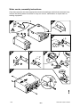
1
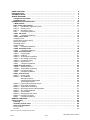
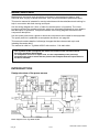
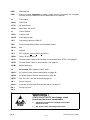
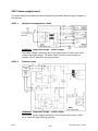
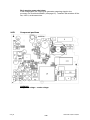
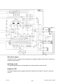
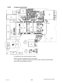
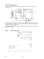
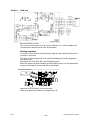
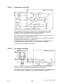
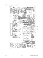
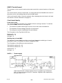
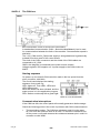
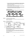
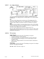
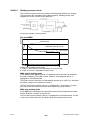
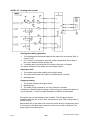
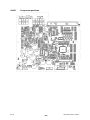
Tig 2200i AC/DC
Caddyt
Service manual
0740 800 179
071123
Valid for serial no. 718--xxx--xxxx
READ THIS FIRST . . . . . . . . . . . . . . . . . . . . . . . . . . . . . . . . . . . . . . . . . . . . . . . . . . . . . . . . . . . . . . . . .
INTRODUCTION . . . . . . . . . . . . . . . . . . . . . . . . . . . . . . . . . . . . . . . . . . . . . . . . . . . . . . . . . . . . . . . . . . .
TECHNICAL DATA . . . . . . . . . . . . . . . . . . . . . . . . . . . . . . . . . . . . . . . . . . . . . . . . . . . . . . . . . . . . . . . . .
WIRING DIAGRAM . . . . . . . . . . . . . . . . . . . . . . . . . . . . . . . . . . . . . . . . . . . . . . . . . . . . . . . . . . . . . . . . .
Component description . . . . . . . . . . . . . . . . . . . . . . . . . . . . . . . . . . . . . . . . . . . . . . . . . . . . . . . . . .
Tig 2200i AC/DC . . . . . . . . . . . . . . . . . . . . . . . . . . . . . . . . . . . . . . . . . . . . . . . . . . . . . . . . . . . . . . . . .
DESCRIPTION OF OPERATION . . . . . . . . . . . . . . . . . . . . . . . . . . . . . . . . . . . . . . . . . . . . . . . . . . . . .
1 MMC module . . . . . . . . . . . . . . . . . . . . . . . . . . . . . . . . . . . . . . . . . . . . . . . . . . . . . . . . . . . . . . . . . .
2AP1 Power supply board . . . . . . . . . . . . . . . . . . . . . . . . . . . . . . . . . . . . . . . . . . . . . . . . . . . . . . .
2AP1:1 Interference suppressor circuit . . . . . . . . . . . . . . . . . . . . . . . . . . . . . . . . . . . . . . . . . . . .
2AP1:2 Primary circuit . . . . . . . . . . . . . . . . . . . . . . . . . . . . . . . . . . . . . . . . . . . . . . . . . . . . . . . . . .
2AP1:3 Secondary circuit . . . . . . . . . . . . . . . . . . . . . . . . . . . . . . . . . . . . . . . . . . . . . . . . . . . . . . .
2AP1
Component positions . . . . . . . . . . . . . . . . . . . . . . . . . . . . . . . . . . . . . . . . . . . . . . . . . . . .
10AP1 TIG board . . . . . . . . . . . . . . . . . . . . . . . . . . . . . . . . . . . . . . . . . . . . . . . . . . . . . . . . . . . . . . . .
10AP1
Component positions . . . . . . . . . . . . . . . . . . . . . . . . . . . . . . . . . . . . . . . . . . . . . . . . . . . .
15AP1 Power board . . . . . . . . . . . . . . . . . . . . . . . . . . . . . . . . . . . . . . . . . . . . . . . . . . . . . . . . . . . . .
Charging circuit . . . . . . . . . . . . . . . . . . . . . . . . . . . . . . . . . . . . . . . . . . . . . . . . . . . . . . . . . . . . . . . . . .
Power factor corrector (PFC) . . . . . . . . . . . . . . . . . . . . . . . . . . . . . . . . . . . . . . . . . . . . . . . . . . . . . . .
Gate driver stages . . . . . . . . . . . . . . . . . . . . . . . . . . . . . . . . . . . . . . . . . . . . . . . . . . . . . . . . . . . . . . . .
Switching circuit . . . . . . . . . . . . . . . . . . . . . . . . . . . . . . . . . . . . . . . . . . . . . . . . . . . . . . . . . . . . . . . . . .
Supply to 2AP1 . . . . . . . . . . . . . . . . . . . . . . . . . . . . . . . . . . . . . . . . . . . . . . . . . . . . . . . . . . . . . . . . . .
15AP1
Component positions . . . . . . . . . . . . . . . . . . . . . . . . . . . . . . . . . . . . . . . . . . . . . . . . . . . .
15AP2 Secondary board . . . . . . . . . . . . . . . . . . . . . . . . . . . . . . . . . . . . . . . . . . . . . . . . . . . . . . . . .
15AP2
Component positions . . . . . . . . . . . . . . . . . . . . . . . . . . . . . . . . . . . . . . . . . . . . . . . . . . . .
18AP1 AC control board . . . . . . . . . . . . . . . . . . . . . . . . . . . . . . . . . . . . . . . . . . . . . . . . . . . . . . . . .
18AP1:1 Power supply . . . . . . . . . . . . . . . . . . . . . . . . . . . . . . . . . . . . . . . . . . . . . . . . . . . . . . . . . . .
18AP1:2 CAN bus . . . . . . . . . . . . . . . . . . . . . . . . . . . . . . . . . . . . . . . . . . . . . . . . . . . . . . . . . . . . . . .
18AP1:3 Temperature monitoring . . . . . . . . . . . . . . . . . . . . . . . . . . . . . . . . . . . . . . . . . . . . . . . . . .
18AP1:4 Arc voltage monitoring . . . . . . . . . . . . . . . . . . . . . . . . . . . . . . . . . . . . . . . . . . . . . . . . . . .
18AP1:5 Fan power supply . . . . . . . . . . . . . . . . . . . . . . . . . . . . . . . . . . . . . . . . . . . . . . . . . . . . . . .
18AP1:6 Switch driver . . . . . . . . . . . . . . . . . . . . . . . . . . . . . . . . . . . . . . . . . . . . . . . . . . . . . . . . . . .
18AP1
Component positions . . . . . . . . . . . . . . . . . . . . . . . . . . . . . . . . . . . . . . . . . . . . . . . . . . . .
18AP2 AC power board . . . . . . . . . . . . . . . . . . . . . . . . . . . . . . . . . . . . . . . . . . . . . . . . . . . . . . . . . .
18AP2:1 Switching circuits . . . . . . . . . . . . . . . . . . . . . . . . . . . . . . . . . . . . . . . . . . . . . . . . . . . . . . .
18AP2:2 Temperature monitoring . . . . . . . . . . . . . . . . . . . . . . . . . . . . . . . . . . . . . . . . . . . . . . . . . .
18AP2:3 Fan power supply . . . . . . . . . . . . . . . . . . . . . . . . . . . . . . . . . . . . . . . . . . . . . . . . . . . . . . .
18AP2
Component positions . . . . . . . . . . . . . . . . . . . . . . . . . . . . . . . . . . . . . . . . . . . . . . . . . . . .
20AP1 Control board . . . . . . . . . . . . . . . . . . . . . . . . . . . . . . . . . . . . . . . . . . . . . . . . . . . . . . . . . . . .
20AP1:1 Power supply . . . . . . . . . . . . . . . . . . . . . . . . . . . . . . . . . . . . . . . . . . . . . . . . . . . . . . . . . . .
20AP1:2 The CAN bus . . . . . . . . . . . . . . . . . . . . . . . . . . . . . . . . . . . . . . . . . . . . . . . . . . . . . . . . . . .
Starting sequence . . . . . . . . . . . . . . . . . . . . . . . . . . . . . . . . . . . . . . . . . . . . . . . . . . . . . . .
Communication interruptions . . . . . . . . . . . . . . . . . . . . . . . . . . . . . . . . . . . . . . . . . . . . .
Terminating resistors . . . . . . . . . . . . . . . . . . . . . . . . . . . . . . . . . . . . . . . . . . . . . . . . . . . .
20AP1:3 Control panel interface circuits . . . . . . . . . . . . . . . . . . . . . . . . . . . . . . . . . . . . . . . . . . . .
20AP1:4 Pulse width modulator . . . . . . . . . . . . . . . . . . . . . . . . . . . . . . . . . . . . . . . . . . . . . . . . . . .
20AP1:5 Temperature monitoring . . . . . . . . . . . . . . . . . . . . . . . . . . . . . . . . . . . . . . . . . . . . . . . . . .
20AP1:6 Shunt and current control amplifier . . . . . . . . . . . . . . . . . . . . . . . . . . . . . . . . . . . . . . . .
20AP1:7 Arc voltage feedback . . . . . . . . . . . . . . . . . . . . . . . . . . . . . . . . . . . . . . . . . . . . . . . . . . . .
20AP1:8 TIG functions . . . . . . . . . . . . . . . . . . . . . . . . . . . . . . . . . . . . . . . . . . . . . . . . . . . . . . . . . . .
20AP1:9 Welding process control . . . . . . . . . . . . . . . . . . . . . . . . . . . . . . . . . . . . . . . . . . . . . . . . .
20AP1:10 Cooling unit control . . . . . . . . . . . . . . . . . . . . . . . . . . . . . . . . . . . . . . . . . . . . . . . . . . . . . .
20AP1
Component positions . . . . . . . . . . . . . . . . . . . . . . . . . . . . . . . . . . . . . . . . . . . . . . . . . . . .
REMOTE CONTROLS . . . . . . . . . . . . . . . . . . . . . . . . . . . . . . . . . . . . . . . . . . . . . . . . . . . . . . . . . . . . . .
FAULT CODES . . . . . . . . . . . . . . . . . . . . . . . . . . . . . . . . . . . . . . . . . . . . . . . . . . . . . . . . . . . . . . . . . . . .
Fault log . . . . . . . . . . . . . . . . . . . . . . . . . . . . . . . . . . . . . . . . . . . . . . . . . . . . . . . . . . . . . . . . . . . . . . . .
Summary of fault codes . . . . . . . . . . . . . . . . . . . . . . . . . . . . . . . . . . . . . . . . . . . . . . . . . . . . . . . . .
Fault code description . . . . . . . . . . . . . . . . . . . . . . . . . . . . . . . . . . . . . . . . . . . . . . . . . . . . . . . . . . .
Power source . . . . . . . . . . . . . . . . . . . . . . . . . . . . . . . . . . . . . . . . . . . . . . . . . . . . . . . . . . . . . . . . . . . .
AC unit . . . . . . . . . . . . . . . . . . . . . . . . . . . . . . . . . . . . . . . . . . . . . . . . . . . . . . . . . . . . . . . . . . . . . . . . . .
4
4
5
6
6
8
10
10
11
11
11
12
13
14
15
16
16
16
17
17
17
18
19
19
20
20
21
22
22
23
23
24
25
25
26
26
26
27
27
29
29
29
30
30
30
31
31
32
32
33
34
35
36
36
36
36
37
37
39
Rights reserved to alter specifications without notice.
TOCe
-- 2 --
S0740 800 179/E071123/P64
SERVICE INSTRUCTIONS . . . . . . . . . . . . . . . . . . . . . . . . . . . . . . . . . . . . . . . . . . . . . . . . . . . . . . . . . .
What is ESD? . . . . . . . . . . . . . . . . . . . . . . . . . . . . . . . . . . . . . . . . . . . . . . . . . . . . . . . . . . . . . . . . . . .
Service aid . . . . . . . . . . . . . . . . . . . . . . . . . . . . . . . . . . . . . . . . . . . . . . . . . . . . . . . . . . . . . . . . . . . . . .
Checking the semiconductor module of 15AP1 . . . . . . . . . . . . . . . . . . . . . . . . . . . . . . . . . . . .
Checking rectifier and freewheel diodes . . . . . . . . . . . . . . . . . . . . . . . . . . . . . . . . . . . . . . . . . .
Checking the IGBT modules of AC power board 18AP2 . . . . . . . . . . . . . . . . . . . . . . . . . . . .
Checking the gate signals to AC power board 18AP2 . . . . . . . . . . . . . . . . . . . . . . . . . . . . . .
Checking the gate pulses . . . . . . . . . . . . . . . . . . . . . . . . . . . . . . . . . . . . . . . . . . . . . . . . . . . . . . . .
Soft starting . . . . . . . . . . . . . . . . . . . . . . . . . . . . . . . . . . . . . . . . . . . . . . . . . . . . . . . . . . . . . . . . . . . .
Mounting components on the heat sink . . . . . . . . . . . . . . . . . . . . . . . . . . . . . . . . . . . . . . . . . . .
INSTRUCTIONS . . . . . . . . . . . . . . . . . . . . . . . . . . . . . . . . . . . . . . . . . . . . . . . . . . . . . . . . . . . . . . . . . . .
SAFETY . . . . . . . . . . . . . . . . . . . . . . . . . . . . . . . . . . . . . . . . . . . . . . . . . . . . . . . . . . . . . . . . . . . . . . . .
INSTALLATION . . . . . . . . . . . . . . . . . . . . . . . . . . . . . . . . . . . . . . . . . . . . . . . . . . . . . . . . . . . . . . . . . .
Lifting instructions . . . . . . . . . . . . . . . . . . . . . . . . . . . . . . . . . . . . . . . . . . . . . . . . . . . . . . . . . . . . . .
Location . . . . . . . . . . . . . . . . . . . . . . . . . . . . . . . . . . . . . . . . . . . . . . . . . . . . . . . . . . . . . . . . . . . . . . . .
Mains power supply . . . . . . . . . . . . . . . . . . . . . . . . . . . . . . . . . . . . . . . . . . . . . . . . . . . . . . . . . . . . .
OPERATION . . . . . . . . . . . . . . . . . . . . . . . . . . . . . . . . . . . . . . . . . . . . . . . . . . . . . . . . . . . . . . . . . . . .
Connections and control devices . . . . . . . . . . . . . . . . . . . . . . . . . . . . . . . . . . . . . . . . . . . . . . . . .
Key to symbols . . . . . . . . . . . . . . . . . . . . . . . . . . . . . . . . . . . . . . . . . . . . . . . . . . . . . . . . . . . . . . . . .
Turning on the power source . . . . . . . . . . . . . . . . . . . . . . . . . . . . . . . . . . . . . . . . . . . . . . . . . . . .
MAINTENANCE . . . . . . . . . . . . . . . . . . . . . . . . . . . . . . . . . . . . . . . . . . . . . . . . . . . . . . . . . . . . . . . . .
Inspection and cleaning . . . . . . . . . . . . . . . . . . . . . . . . . . . . . . . . . . . . . . . . . . . . . . . . . . . . . . . . .
Water cooler, assembly instructions . . . . . . . . . . . . . . . . . . . . . . . . . . . . . . . . . . . . . . . . . . . . . .
FAULT--TRACING . . . . . . . . . . . . . . . . . . . . . . . . . . . . . . . . . . . . . . . . . . . . . . . . . . . . . . . . . . . . . . . .
SPARE PARTS . . . . . . . . . . . . . . . . . . . . . . . . . . . . . . . . . . . . . . . . . . . . . . . . . . . . . . . . . . . . . . . . . . . .
NOTES . . . . . . . . . . . . . . . . . . . . . . . . . . . . . . . . . . . . . . . . . . . . . . . . . . . . . . . . . . . . . . . . . . . . . . . . . . .
42
42
42
44
47
48
50
53
54
56
58
58
58
58
58
58
59
59
59
60
60
60
61
62
62
62
Rights reserved to alter specifications without notice.
TOCe
-- 3 --
S0740 800 179/E071123/P64
READ THIS FIRST
Maintenance and repair work should be performed by an experienced person, and
electrical work only by a trained electrician. Use only recommended replacement parts.
This service manual is intended for use by technicians with electrical/electronic training for
help in connection with fault--tracing and repair.
Use the wiring diagram as a form of index for the description of operation. The circuit
boards are divided into numbered blocks, which are described individually in more detail in
the description of operation. Component names in the wiring diagram are listed in the
component description.
Use the spare parts list as a guide to where the components are located in the equipment.
The spare parts list is published as a separate document, see page 62.
This manual contains details of all design changes that have been made up to and
including November 2007.
The manual is valid for: Tig 2200i AC/DC with serial no. 718--000--0000
The Tig 2200i AC/DC is designed and tested in accordance with international and
European standards IEC/EN 60974.
On completion of service or repair work, it is the responsibility of the person(s)
performing the work to ensure that the product still complies with the requirements of
the above standard.
INTRODUCTION
Design structure of the power source
Block diagram of the Tig 2200i AC/DC
ct33_00
-- 4 --
S0740 800 179/E071123/P64
The power source is transistor--controlled, operating on the inverter principle. It consists of a
number of function modules, as shown in the block diagram above. Each module has a
module number, which is always included as the first part of the name/identification of
components in the module.
The modules have the following main functions:
1 MMC module
Control panel and display board.
2 Mains module
Mains interference suppressor, mains switch, auxiliary transformer, contactor.
10 TIG module
Torch switch interface, HF unit, gas valve.
15 Power module
This module is a single forward converter, operating at a switching frequency of 65 kHz.
IGBT transistors are used as the switching elements. All power semiconductors are built
into modules.
18 AC module
Comprises all AC TIG functions.
20 Processor board module (controller module)
This is the controller board, 20AP1, that monitors and controls the power source. The micro
processor of the board comprises the welding data unit.
TECHNICAL DATA
Tig 2200i AC/DC
Mains voltage
230V ±10%, 1∼ 50 Hz
Primary current
Imax TIG
Imax MMA
27.4 A
25.0 A
Fuse (anti--surge or type C MCB)
16 A
Open--circuit power
40 W
Setting range
TIG AC* / DC
MMA
3 -- 220 A
4 -- 160 A
Permissible load at TIG AC/DC
20% duty cycle
60% duty cycle
100% duty cycle
220 A / 18.8 V
150 A / 16.0 V
140 A / 15.6 V
Permissible load at MMA
30% duty cycle
60% duty cycle
100% duty cycle
160 A / 26.4 V
120 A / 24.8 V
110 A / 24.4 V
Power factor at maximum current
TIG
MMA
0.99
0.99
Efficiency at maximum current
TIG
MMA
66 %
74 %
Open--circuit voltage without VRD function
with VRD function
70 V
30 V
ct33_00
-- 5 --
S0740 800 179/E071123/P64
Tig 2200i AC/DC
Operating temperature
--10 to + 40˚C
Transportation temperature
--25 to + 55˚C
Constant sound pressure in open--circuit
< 70 dB (A)
Dimensions, l x b x h
418 x 188 x 345 mm
Weight
15.7 kg
Shielding gas
All types intended for TIG welding
max pressure
5 bar
Insulation class transformer
H
Enclosure class
Application class
IP 23
*) The minimum current during AC welding depends on the alloy used for the aluminium plates and
their surface cleanliness.
Duty cycle
The duty cycle refers to the time as a percentage of a ten--minute period that you can weld at a certain load without overloading.
The duty cycle is valid for 40˚C ambient temperature.
Enclosure class
The IP code indicates the enclosure class, i. e. the degree of protection against penetration by solid
objects or water. Equipment marked IP23 is designed for indoor and outdoor use.
Application class
The symbol
indicates that the power source is designed for use in areas with increased
electrical hazard.
WIRING DIAGRAM
The power source is based on a number of function modules. These are described in the
component descriptions on the following pages. Wire numbers and component names in
the wiring diagram show to which module each component belongs.
Circuit boards within each module have names such as 15AP1 -- 15AP99.
15 = module association, 1--69
AP = circuit board
1
= individual identification number, 0--99
Components within modules are named in a similar way.
Component description
1
MMC module: control panel and display board, see page 10.
2
Mains module.
2AP1
Power supply board.
2L1--2L7
Ferrite ring cores.
ct33_00
-- 6 --
S0740 800 179/E071123/P64
2QF1
Mains switch.
2XS1
Flat pin sockets. Important: to obtain a proper electric connection, the complete
cord set must be replaced if the sockets have to be replaced.
10
TIG module.
10AP1
TIG board.
10TV1
HF transformer.
10YV1
Gas valve, 230 V AC.
15
Power module.
15AP1
Power board.
15AP2
Secondary board.
15C1
Smoothing capacitor, 2200 uF.
15D1
Diode module with rectifier and freewheel diodes.
15EV1
Fan.
15L1
Inductor.
15L2
PFC Inductor (Power Factor Corrector)
15RS1
Shunt. 60 mV at 100 A.
15ST1
Thermal switch, fitted in the winding of main transformer 15TM1. See page 31.
15ST2
Thermal switch, fitted on the heat sink. See page 31.
15TM1
Main transformer.
18
AC module. Wire numbers 1800--1999.
18AP1
AC control board. See the description on page 20.
18AP2
AC power board. See the description on page 25.
18EV1
Fan, 24 V DC. See the description page 23.
18L1
Ferrite ring core.
20AP1
Controller circuit board. See the description on page 27.
20L1,
20L2
Ferrite ring core.
WARNING !
STATIC ELECTRICITY can damage circuit
boards and electronic components.
ESD
ct33_00
S
Observe precautions for handling electrostatic-sensitive devices.
S
Use proper static--proof bags and boxes.
-- 7 --
S0740 800 179/E071123/P64
Tig 2200i AC/DC
ct33_00
-- 8 --
S0740 800 179/E071123/P64
ct33_00
-- 9 --
S0740 800 179/E071123/P64
DESCRIPTION OF OPERATION
This description describes the function of circuit boards and other components in the power
source. It is divided into sections, numbered to correspond to the circuit board numbers and
divisions into function blocks.
1 MMC module
The MMC module consists of an operator’s control panel and a display board.
The control panel is used for setting and displaying welding data. The welding data are
stored by the control board of the power source.
The control panels are described in separate instruction and service manuals.
TA33 AC/DC
intended for MMA--, AC TIG-- and DC TIG welding without pulsing.
TA34 AC/DC
intended for MMA--, AC TIG-- and DC TIG welding with pulsing.
S
TA33 AC/DC
S
TA34 AC/DC
Pushbuttons are used for parameter selection and a knob for parameter settings, current, time etc.
ct33_01
-- 10 --
S0740 800 179/E071123/P64
2AP1 Power supply board
The power supply board filters the mains voltage and generates internal supply voltages for
the machine.
2AP1:1
Interference suppressor circuit
WARNING! Dangerous voltage - mains voltage.
The mains voltage is filtered by the power supply board. Power board 15AP1
rectifies the mains voltage. TIG board 10AP1 uses the mains voltage for
supply to the HF generator and the gas valve.
2AP1:2
Primary circuit
WARNING! Dangerous voltage - mains voltage.
The primary circuit is supplied with 325 V DC from the power board, 15AP1.
S1 is a fuse with high rupturing capacity.
ct33_02
-- 11 --
S0740 800 179/E071123/P64
Transistor Q5 is the switching element in a switched voltage supply. The
secondary voltage, +24 V, is sensed by IC2 and controlled by IC1.
The isolation voltage of transformer T1 and optocoupler IC3 is 4 kV.
+15V A
Internal power supply to 2AP1 and power supply to the PFC circuits of the
power board, 15AP1.
The voltage is controlled by VR1, it has a tolerance of ±0.75V.
2AP1:3
Secondary circuit
The secondary circuit delivers the following voltages:
+24 V
The voltage is controlled by IC1 on the primary side. It has a tolerance of
±0.6 V.
+5 V
The voltage is controlled by VR3. It has a tolerance of ±0.25 V.
--15 V
The voltage is controlled by VR2. It has a tolerance of ±0.75 V.
+13 VB (+12V CAN)
This voltage is unregulated. It has a tolerance of ±1.5 V.
ct33_02
-- 12 --
S0740 800 179/E071123/P64
Early warning power shut down
If the voltage goes low, output PS4 generates a warning signal to the
processor on circuit board 20AP1 (see page 27). Transistor Q6 switches off the
fan, 15EV1, at the same time.
2AP1
Component positions
WARNING!
Dangerous voltage - mains voltage.
ct33_02
-- 13 --
S0740 800 179/E071123/P64
10AP1 TIG board
WARNING!
Dangerous voltage - mains voltage.
The relay contacts, the gas valve 10YV1, the HF generator TR2 and the primary side of
transformer TR1 are connected to 230 V mains voltage.
The processor on circuit board 20AP1 controls the HF generator and gas valve.
HF generator
When the welding torch switch is operated, and the open--circuit voltage is over 50 V, relay
RE2 closes and turns on the HF generator, TR2. It remains activated until the arc strikes, or
for a maximum of 0.7 seconds.
The voltage on the primary side of HF transformer 10TV1 is about 550 V. The secondary
voltage is about 11 kV if a 4 metre long welding torch is connected. If the welding torch is 16
metre long, the HF spark is about 8 kV.
Due to electromagnetic interference regulations, the energy in the HF ignition spark is
limited, and so the HF spark weakens with increasing length of the torch. The HF ignition is
satisfactory for welding torches up to 16 metres.
Gas valve
When the torch switch is operated, relay RE1 closes and energizes the gas valve.
When the torch switch is released and the gas post--flow time has elapsed, the gas valve is
deactivated.
TIG torch switch
The secondary windings of transformer TR1 and rectifier bridge D3--D6 produce 24 V DC.
This voltage energizes relay RE3 when the torch switch is closed.
ct33_10
-- 14 --
S0740 800 179/E071123/P64
10AP1
Component positions
WARNING!
Dangerous voltage - mains voltage.
ct33_10
-- 15 --
S0740 800 179/E071123/P64
15AP1 Power board
WARNING!
Dangerous voltage - mains voltage.
Never make any measurements on this board
when the machine is connected to the mains
supply.
The power module is a single forward converter,
operating at a switching frequency of 65 kHz.
IGBT transistors are used as the switching
elements. See pages 44 to 47 and 53 to 55 for
measurement instructions.
If the power board has failed, a replacement
board must be mounted in accordance with the
instructions on page 56.
The power board carries the mains rectifier, the
charging circuit, the PFC circuit, the gate circuits
and the switching circuits.
The mains rectifier, the switching transistors and
parts of the charge and PFC circuits are
integrated in a semiconductor module, PM1,
which is part of the power board.
Charging circuit
When the mains power supply is turned on, the rectified mains voltage charges smoothing
capacitor 15C1 via resistor R31. Thyristor TY1 short--circuits charge resistor R31 when the
machine is loaded. If TY1 did not conduct, resistor R31 would burn out when the unit is on
load.
Power factor corrector (PFC)
The aim with the power factor corrector is to keep the mains current sinusoidal and in phase
with the mains voltage. The PFC circuit holds the intermediate voltage at 365 V. At mains
currents above 26 A the PFC does not work, the intermediate voltage is then 325 V or less.
When the PFC is operatiing properly the voltage across capacitor 15C1 is 365 V.
ct33_15_1
-- 16 --
S0740 800 179/E071123/P64
Gate driver stages
Transformer TR1 is a gate driver transformer for galvanic isolation of the drive circuits from
controller board 20AP1.
Switching circuit
The switching transistors are integrated in the semiconductor module, PM1.
Supply to 2AP1
The board supplies power supply board 2AP1 with 325 V DC (pins F1 and F3, connector
15XS1).
ct33_15_1
-- 17 --
S0740 800 179/E071123/P64
15AP1
Component positions
Pin positions of the semiconductor module:
(Seen from the component side of the board).
Pin 1 marked P1 starts in the down--left corner and continuous anticlockwise
around the semiconductor module.
ct33_15_1
-- 18 --
S0740 800 179/E071123/P64
15AP2 Secondary board
The secondary board is fitted on the main transformer 15TM1, diode module 15D1 and
inductor 15L1.
Diode module 15D1 comprises two diodes, rectifier and freewheel diode. During the time
interval between two voltage pulses from transformer 15TM1, the freewheel diode maintain
the welding current from inductor 15L1.
If the diode module has failed, a replacement module must be fitted in accordance with the
instructions on page 56.
15AP2
ct33_15_2
Component positions
-- 19 --
18AP1 AC control board
Sections 18AP1:1 to 18AP1:6 refer to the wiring diagram on page 8.
The processor on the AC control board monitors the temperature in the AC power modules.
The AC control commands are generated by the processor on circuit board 20AP1 and
executed by the local processor.
Circuit board identity
The AC control board has a machine ID, a hardware ID and a unit type number. To read this
you need the ESAT service kit, see page 43.
S The machine ID determines which type of power source the board is intended for.
S The hardware ID shows design and type of circuit board.
S The unit type is used for identification on the can bus.
The ID numbers of this board are:
Machine ID = 1
Hardware ID = 1
Unit type = 5
18AP1:1
Power supply
The AC control board comprises a switched voltage regulator. This is used in
order to provide galvanic separation of the IGBT drive voltages, 4 x 17 V and
4 x --11 V. The voltages can be tested by checking the gate signals to the AC
power board, see page 50. If the --11 volt is outside the limits 10.45 to 11.55 V,
fault code 9 is displayed.
The +5 V and +15 V are used for internal power supply on the board.
If the +5 V is outside the limits 4.75 to 5.25 V, fault code 4 is displayed.
If the +15 V is outside the limits 14.25 to 15.75 V, fault code 8 is displayed.
Measuring points are shown on page 24.
ct33_18
-- 20 --
S0740 800 179/E071123/P64
18AP1:2
CAN bus
Bus communication circuits
The circuit board includes a driver for the CAN bus, IC17, which handles the
communication with the other units of the system.
Starting sequence
On power--up, the board’s CAN controller reads the bus speed from the micro
processor: 400 kbit/s.
The light--emitting diodes D30, D31 and D32 displays the starting sequence
from power--up:
D30 lights red. Then D30, D31 and D32 lights green.
When the board has been initiated, and the power source is in the application
program, D30 flashes continously with a green light.
LEDs D30, D31 and D32 on circuit board 18AP1
Read more about the CAN bus on pages 29 to 30.
ct33_18
-- 21 --
S0740 800 179/E071123/P64
18AP1:3
Temperature monitoring
Principle diagram of the temperature monitoring circuits
The temperature monitoring circuit senses the temperature of the IGBT
modules, IC1 and IC2, that are fitted to circuit board 18AP2. Two NTC
resistors, NTC_IC1 and NTC_IC2, are used as sensors.
The output of the monitoring circuit is sensed by the processor, which in turn
stops the machine if overtemperature occurs.
If the temperature exceeds 110 _C the power source is stopped. It cannot be
restarted until the temperature is below 55 _C.
If overtemperature is sensed by NTC_IC1, fault code 7 is displayed and if
overtemperature is sensed by NTC_IC2, fault code 6 is displayed.
To check the NTC resistors: see page 50.
18AP1:4
Arc voltage monitoring
The arc voltage monitoring circuits measures the output voltage from the
power source. The voltage is displayed by the control panel.
The welding process control and no--load voltage reduction are maintained by
circuit board 20AP1, see 20AP1:7 Arc voltage feedback on page 32.
ct33_18
-- 22 --
S0740 800 179/E071123/P64
18AP1:5
Fan power supply
The fan is supplied at 24 V DC from the power supply board,
18AP1:6
Switch driver
See also 18AP2:1 Switching circuits on page 25.
The gate signals can be measured on circuit board 18AP2. See page 50 for
test instructions.
ct33_18
-- 23 --
S0740 800 179/E071123/P64
18AP1
ct33_18
Component positions
-- 24 --
S0740 800 179/E071123/P64
18AP2 AC power board
Sections 18AP2:1 to 18AP2:3 refer to the wiring diagram on page 8.
18AP2:1
Switching circuits
The circuit board carries two IGBT modules IC1 and IC2, with 2 IGBTs each. In
the description below the IGBTs are named IGBT1, IGBT2, IGBT3 and IGBT4.
The IGBTs are controlled by the processor.
All IGBTs are conducting during the starting sequence of the power source
(mains switch power on).
MMA
IGBT1 and IGBT4 are conducting.(positive electrode)
If MMA with negative electrode is selected, IGBT2 and IGBT3 are conducting.
TIG DC
When welding start is activated IGBT1 and IGBT4 conducts.(positive
electrode)
During welding IGBT2 and IGBT3 are conducting (negative electrode).
TIG AC
When welding start is activated IGBT1 and IGBT4 conducts.
During welding IGBT1 and IGBT4 conducts in turns with IGBT2 and IGBT3.
IGBT gate signals
The IGBT gate signals can be measured across varistors D4, D8, D12 and
D16. See page 50 for test instructions.
ct33_18
-- 25 --
S0740 800 179/E071123/P64
18AP2:2
Temperature monitoring
See 18AP1:3 on page 22.
18AP2:3
Fan power supply
See 18AP1:5 on page 23.
18AP2
ct33_18
Component positions
-- 26 --
S0740 800 179/E071123/P64
20AP1 Control board
The processor on the control board monitors and controls the various functions of the power
source.
The control board is used in combi mode. In combi mode the board handles the control of
the power source, the welding data unit and the MMC panel.
If the circuit board is faulty, it must be replaced. After replacing the circuit board, soft--start
the machine. See the instructions on page 54.
Circuit board identity
Power source unit
The control board has a machine ID, a hardware ID and a unit type number. To read this
you need the ESAT service kit, see page 43.
S
S
S
The machine ID defines which type of power source the board is intended for.
The hardware ID shows design and type of circuit board.
The unit type is used for identification on the CAN bus.
The ID numbers of the Tig 2200i AC/DC are:
Machine ID = 34
Hardware ID = 4
Unit type = 2
Welding data unit and MMC
The machine ID for the MMC part of the control board determines which type of control
panel that is used. The machine ID can be changed by ESAT.
The ID numbers of the different control panels are:
TA33 AC/DC machine ID = 23
TA34 AC/DC machine ID = 19
Hardware ID = 4
Unit type = 0
20AP1:1
Power supply
+5V and +2.5V
IC6 monitors the 24 V voltage supply to the 5 V regulator on circuit board
2AP1. IC16 monitors the 5 and 2.5 V supplies. Regulator VR4 supplies the
processor with +2.5 V.
ct33_20
-- 27 --
S0740 800 179/E071123/P64
The voltage on terminal PS4 is normally about 24 V, when this drops below
20 V, pin 14 of IC6 goes low, providing the processor with a low power supply
voltage signal. The processor then stores current data and generates fault
code E4. When the 5 and 2.5 V voltages are passing below their treshold
values, the processor receives a reset signal from IC16.
Fault code E4 is not displayed at normal power off
+15V and +20V
Voltage regulator VR2 produces an output voltage of +20 ±1.0 V, which
supplies the pulse width modulator output stage.
Potential divider R70/R75 supplies 2.6 V to the processor. This provides a
signal that the power supply is available.
Voltage regulator VR1 produces an output voltage of +15 V, and this, together
with the --15 V supply, powers the analogue circuits.
--15V
The --15 V power supply is monitored by the processor.
+12 V_CAN
The +13VB from 2AP1 is used to supply the CAN circuits of the equipment.
This supply is referred to as + 12V_CAN, its neutral point, 0V_CAN, is
separated from the electronic neutral (0 V).
The tolerance of the voltage is 11.5 to 14.5 V.
ct33_20
-- 28 --
S0740 800 179/E071123/P64
20AP1:2
The CAN bus
Bus communication circuits to and from the control board
A standardised communication (CAN -- Controller Area Network) bus is used
for communication between the units of the machine. Communication speed is
400 kbit/s.
The +12V_CAN and 0V_CAN power supply is unregulated and is galvanically
isolated from other parts of the control board.
The shell of the CAN--connectors and the shield of the CAN cables are
connected to 0V_CAN.
GND in the diagram is connected to the power source chassis.
Voltage regulator VR5 supplies a 5 V power supply to the CAN circuits on
20AP1.
Starting sequence
On power--up, the board’s CAN controller reads in the bus speed from the
micro processor: 400 kbit/s.
The circuit board displays the starting
sequence from power--up.
LED1 lights red. Then LED1, LED2 and
LED3 lights green.
When the board has been initiated, and the
power source is in the application program,
LED1 flashes continously with a green light.
LEDs on circuit board 20AP1
Communication interruptions
If the CAN bus fails, the control panel will normally generate a fault message.
Check the following points in the event of problems with CAN communications:
S
ct33_20
The terminating resistor. The CAN bus resistance must lie in the range
50--130 ohm: the optimum value is 60 ohm. To check the resistance, turn
off the power source and measure the resistance between pins L and K in
connector socket XS25.
-- 29 --
S0740 800 179/E071123/P64
S
All screen connections must be sound. Measure the resistance between
the shell of the CAN connector connected to 20AP1 and the shell of CAN
connector XP55 connected to 18AP1. There must be a short circuit
between those two end points.
S
Good contact with the chassis connections from/to the circuit boards and
suppressor capacitors. See the main circuit diagram.
S
The connection cable between units. Check that the correct type of cable
is being used. Check that each signal is being carried by the correct core.
CAN H and CAN L must be carried by the twinned pair.
Terminating resistors
In order to avoid communication interference, the ends of the CAN bus must
be terminated by resistive loads.
Principle diagram of the CAN bus and connecting up of the terminating resistors
20AP1:3
Control panel interface circuits
See the service manual for the TA33 AC/DC and TA34 AC/DC control panels,
filename: 0740 800 180.
20AP1:4
Pulse width modulator
The pulse width modulator determines the frequency and pulse time of the
switching transistors’ control pulses. IC3 controls the pulse frequency, the
pulse time and inhibition of pulses.
The pulse frequency is 65 kHz +/-- 1kHz, with a maximum pulse width of 43 -44 % of the cycle width. See page 53 for screen traces of waveforms and
measurement instructions.
Transistor Q5 controls the primary winding of the pulse transformer on circuit
board 15AP1.
ct33_20
-- 30 --
S0740 800 179/E071123/P64
20AP1:5
Temperature monitoring
The thermal overload switches, 15ST1 and 15ST2, are normally closed.
Terminal T2 of the circuit board is at 0 V.
15ST2, which is fitted on the heat sink, opens at 75 _C. 15ST1, which is fitted
in the winding of the main transformer, 15TM1, opens at 130 _C.
If either of the switches operates, the power source is stopped, fault code E06
is displayed.
The power source cannot be restarted until it has cooled sufficiently for the
switch(es) to reclose.
20AP1:6
Shunt and current control amplifier
The shunt produces 60 mV at a welding current of 100 A. The shunt response
is linear to the welding current.
If the shunt is not connected to the circuit board, resistor R2 supplies about
1.4 to 1.9 V to the shunt input. This blocks the current control amplifier, i.e. the
machine does not deliver any welding current.
ct33_20
-- 31 --
S0740 800 179/E071123/P64
20AP1:7
Arc voltage feedback
This circuit measures and scales the arc voltage to a suitable level for the
processor. 64 V arc voltage produces a voltage signal of 5.0 V at the cathode
of diode D13.
TIG
The open--circuit voltage control is inactive in the TIG welding mode. The
open--circuit voltage is about 110 V. Arc voltages below 45 V are defined as
welding. Output voltage is produced only when TIG welding is in progress.
MMA
When the current exceeds 10 A during welding start, the open--circuit voltage
control is deactivated. When the arc voltage exceeds 52 V, welding stops and
the open--circuit voltage control is activated.
The open--circuit voltage control holds the voltage at about 70 V.
When the VRD (Voltage Reduction Device) function is active, the open--circuit
voltage is about 30 V. The VRD function can only be activated or deactivated
by the ESAT, see page 43.
20AP1:8
TIG functions
LiftArc TIG start
Output voltage is produced only when TIG welding is in progress.
S Touch the electrode on to the workpiece.
S Press the torch trigger. The machine produces a current of about 6 A.
S Lift the electrode from the workpiece. The arc strikes and the current
increases to 30 A.
S When the arc voltage exceeds 8 V, the current increases / decreases to
the set current.
HF TIG start
Output voltage is produced only when TIG welding is in progress. Arc voltages
below 45 V are defined as welding.
See also: 10AP1 TIG board, on page 14.
ct33_20
-- 32 --
S0740 800 179/E071123/P64
20AP1:9
Welding process control
The processor inputs are the set values of welding data and the arc voltage.
The processor also calculates a set value signal for welding current, and
supplies this to the current control amplifier.
The process regulator control principle
Current
Hot start MMA
Peak current
Adjustable starting current
Set current
1
2
Starting current, MMA welding mode
1. Phase 1, fixed starting current depending on the set current.
2. Phase 2, hot start = adjustable starting current.
Time
MMA normal welding mode
In the MMA normal welding mode, the welding current is briefly increased at
the start of welding. The peak current, phase 1 in the diagram above, is
engaged for 150 milliseconds.
The peak current is twice the normal welding current up to 160 A (i.e. twice the
set value), subject to a maximum of 240 A.
The hot start current, phase 2 above, is engaged for 1.5 seconds. It is set in
per cent of the set current, but does never exceed the peak current.
MMA drop welding mode
In the MMA drop welding mode, the peak current is three times the set value,
but the duration is shorter at only 50 ms.
The hot start current, phase 2 above, is engaged for 240 milliseconds. It is set
in per cent of the set current, but does never exceed the peak current.
ct33_20
-- 33 --
S0740 800 179/E071123/P64
20AP1:10 Cooling unit control
Starting the welding equipment
1.
2.
3.
The welding data unit senses whether the water lock microswitch, 5S2, is
closed or not.
If it is closed, a command to start the pump is generated, and a relay in
the cooler starts the pump and the fan.
If welding does not start within 6.5 minutes, the pump is stopped.
The pump is stopped if the water lock microswitch opens.
Starting to weld
1.
2.
3.
The welder presses the welding torch trigger switch.
The water pump starts if the water lock microswitch is closed.
Welding starts.
Stopping welding
1.
2.
3.
The welder releases the trigger switch.
Welding stops.
The water pump continues to run for a further 6.5 minutes.
If welding is restarted while the pump is still running, the pump will continue to
run as required, i.e. the 6.5 minute shutdown countdown is interrupted.
Flow guard can not be installed in the CoolMini. The flow guard input is
jumpered with wire 541 in the cooler, the behaviour is as if the cooling water is
always flowing.
Microswitch 5S2 in the water lock connector closes when a cooling water hose
is connected to the blue water connector on the front of the cooling unit. The
pump stops if the switch opens.
ct33_20
-- 34 --
S0740 800 179/E071123/P64
20AP1
ct33_20
Component positions
-- 35 --
S0740 800 179/E071123/P64
REMOTE CONTROLS
A number of remote control units can be connected to the power source, these are
described in a separate service manual with filename 0740 800 170.
FAULT CODES
Fault codes are used in order to indicate and identify a fault in the equipment.
Fault log
All faults that occur when using the welding equipment are documented as error messages
in the fault log. When the fault log is full, the oldest message will automatically erase when
the next fault occurs.
Only the most recent fault message is displayed on the control panel. To read the entire
fault log, the machine must be connected to the ESAT: see service tools on page 43.
Faults are monitored/detected in two ways: by test routines that are run on initiation and by
functions that can detect a fault when it occurs.
The control panel displays a unit number to indicate which unit has generated the fault. The
following unit numbers are used:
U0 = welding data unit
U4 = remote control unit
U2 = power source
U5 = AC unit
Summary of fault codes
Code
Description
Welding
data
unit
Power
source
Remote AC
control unit
unit
*1 Memory error, EPROM
x
x
*2 Memory error, RAM
x
x
x
*3 Memory error, external RAM
x
x
x
4 +5 V power supply
x
x
6 High temperature
x
x
x
7 High temperature
x
x
*8 Power supply 1
x
x
*9 Power supply 2
x
x
x
x
12 Communication error (warning)
x
x
13 High temperature external
x
*14 Communication error (bus off)
x
15 Lost messages
x
16 High open--circuit voltage (VRD)
x
x
*18 Lost contact with the power source
x
*19 Memory error in data memory
x
ct33f1
x
-- 36 --
S0740 800 179/E071123/P64
Description
Code
Welding
data
unit
20 High inductance in the welding circuit
Power
source
Remote AC
control unit
unit
x
*22 Transmitter buffer overflow
x
x
x
*23 Receiver buffer overflow
x
x
x
*25 Lost contact with AC unit
x
*26 Program operating fault
x
*28 Stack overflow
x
x
x
*40 Incompatible units
x
Fault codes marked with an asterisk ( * ) are not displayed by the control panel. but they
are stored in the fault log. To get access to the fault log use the ESAT service tool. See
page 43.
Fault code description
This manual describes the fault codes for the power source and the AC unit. The fault
codes for the other units are described in the manuals for these units.
Note! The welding data unit is operated by the processor of the control board in the power
source. The fault codes for the welding data unit are described in the service manual for the
control panel.
Power source
Code Description, power source
1
EPROM check sum error -- program memory error
Check sum test of the program memory, which is run only when initiating the power source
after power--up. This fault does not disable any functions.
The program memory is damaged. This is a serious fault, that can have unforeseen effects.
Action: Restart the machine. If the fault persists, load new software via ESAT. If the fault still
persists, replace circuit board 20AP1, which carries the memory chip.
2
Microprocessor RAM error
The microprocessor is unable to read/write from/to a particular memory address in its
internal memory. This test is preformed only on initiation after power--up. This fault does not
disable any functions.
Action: Restart the machine. If the fault persists, replace circuit board 20AP1, which carries
the microprocessor chip.
3
Error in external RAM
Read/write test of the processor’s internal external RAM. This test is preformed only as part
of initiation after power--up. The microprocessor is unable to read/write from/to a particular
memory address in its external memory. This fault does not disable any functions.
Action: Restart the machine. If the fault persists, replace circuit board 20AP1, which carries
the microprocessor chip.
ct33f1
-- 37 --
S0740 800 179/E071123/P64
Code Description, power source
4
5 V power supply too low
The unregulated power supply voltage (+24 V) is too low: the smoothing capacitors cannot
keep the voltage up enough for the processor to continue to operate. The processor stops all
normal activities, expecting to be shut down.
Action: Turn off the mains power supply to reset the unit. If the fault persists, check the
power supply to circuit board 20AP1.
6
High temperature
The temperature monitoring circuit has operated. The power source is stopped, and cannot
be restarted until the circuit has reset. See also page 31.
Possible causes: Overloading, fan not working properly, cooling air inlets or outlets blocked
or obstructed or dirt on the heat exchanger.
12
Communication error (warning)
The load on the system CAN bus is temporarily too high, or there is electric noise on the
bus.
Action: Check the equipment to ensure that only one remote control unit is connected. See
also section 20AP1:2 ’The CAN bus’ on pages 29 to 30.
15
Lost messages
The bus CAN controller indicates that a message has been lost. No functions are disabled
by this fault.
Action: Check that all units are correct connected to the CAN bus. See also section
20AP1:2 ’The CAN bus’ on pages 29 to 30.
16
High open--circuit voltage (VRD)
The open--circuit voltage has been too high.
Action: Turn off the mains power supply to reset the unit. If the fault persists, check the arc
voltage feedback: see page 32.
20
High inductance in the welding circuit
The power source cannot produce the desired current because the measured inductance in
the welding circuit is too high. The fault indication is reset if the inductance reading receives
a sufficiently low value at weld start. Resetting can also be achieved by turning off the power.
Action: Use shorter welding cables and ensure that the cables are not coiled up. Place the
welding cable and connector cable next to each other. If possible, the inductance can be
reduced by welding with a shorter arc.
22
Transmitter buffer overflow
The control board is unable to transmit information to the other units at a sufficiently high
speed.
Action: A break in the bus line can cause this fault. Check the CAN cabling. Turn off the
mains power supply to reset the unit.
23
Receiver buffer overflow
The control board is unable to process information from the other units at a sufficiently high
speed. This fault is caused by abnormal loading of the microprocessor.
Action: Turn off the mains power supply to reset the unit.
ct33f1
-- 38 --
S0740 800 179/E071123/P64
AC unit
Code Description, AC unit
1
EPROM check sum error -- program memory error
Check sum test of the program memory, which is run only when initiating the unit after
power--up. This fault does not disable any functions.
The program memory is damaged. This is a serious fault, that can have unforeseen effects.
Action: Restart the machine. If the fault persists, load new software via ESAT. If the fault still
persists, replace circuit board 18AP1, which carries the memory chip.
2
Microprocessor RAM error
The microprocessor is unable to read/write from/to a particular memory address in its
internal memory. This test is preformed only on initiation after power--up. This fault does not
disable any functions.
Action: Restart the machine. If the fault persists, replace circuit board 18AP1, which carries
the microprocessor chip.
3
Error in external RAM
Read/write test of the processor’s internal external RAM. This test is preformed only as part
of initiation after power--up. The microprocessor is unable to read/write from/to a particular
memory address in its external memory. This fault does not disable any functions.
Action: Restart the machine. If the fault persists, replace circuit board 18AP1, which carries
the microprocessor chip.
4
+5 V power supply on circuit board 18AP1
The voltage is too high or too low: it must be within the range 4.75 -- 5.25 V. This fault does
not disable any functions.
Action: Turn off the mains power supply to reset the unit. If the fault persists, check the
power supply to circuit board 18AP1.
6
High temperature NTC_IC2
The temperature monitoring circuit has operated. The power source is stopped, and cannot
be restarted until the circuit has reset. See also page 22.
Possible causes: Overloading, fan not working properly, cooling air inlets or outlets blocked
or obstructed or dirt on the heat exchanger.
7
High temperature NTC_IC1
The temperature monitoring circuit has operated. The power source is stopped, and cannot
be restarted until the circuit has reset. See also page 22.
Possible causes: Overloading, fan not working properly, cooling air inlets or outlets blocked
or obstructed or dirt on the heat exchanger.
8
+15 V power supply on circuit board 18AP1
The voltage is too high or too low: it must be within the range 14.25 -- 15.75 V. This fault
does not disable any functions.
9
--11 V power supply on circuit board 18AP1
The voltage is too high or too low: it must be within the range 10.45 -- 11.55 V. This fault
does not disable any functions.
ct33f1
-- 39 --
S0740 800 179/E071123/P64
Code Description, AC unit
12
Communication error (warning)
The load on the system CAN bus is temporarily too high, or there is electric noise on the
bus.
Action: Check the equipment to ensure that only one remote control unit is connected. See
also section 20AP1:3 ’The CAN bus’ on pages 29 to 30.
13
High temperature external
The temperature monitoring circuit has operated. The power source is stopped, and cannot
be restarted until the circuit has reset.
Fault code 13 does not normally occur at standard equipment. The sensing input is bridged
by a resistor on circuit board 18AP2, see page 22.
22
Transmitter buffer overflow
The board is unable to transmit information to the other units at a sufficiently high speed.
Action: A break in the bus line can cause this fault. Check the CAN cabling. Turn off the
mains power supply to reset the unit.
23
Receiver buffer overflow
The board is unable to process information from the other units at a sufficiently high speed.
This fault is caused by abnormal loading of the microprocessor.
Action: Turn off the mains power supply to reset the unit.
28
Stack overflow
The stack memory is full.
This fault should never occur in reality: the fault code is intended as an aid during
development work. Contact ESAB if the fault does occur.
ct33f1
-- 40 --
S0740 800 179/E071123/P64
ct33f1
-- 41 --
S0740 800 179/E071123/P64
SERVICE INSTRUCTIONS
WARNING !
STATIC ELECTRICITY can damage circuit
boards and electronic components.
ESD
S
Observe precautions for handling electrostatic-sensitive devices.
S
Use proper static--proof bags and boxes.
What is ESD?
A sudden transfer or discharge of static electricity from one object to another. ESD stands for
Electrostatic Discharge.
How does ESD damage occur?
ESD can cause damage to sensitive electrical components, but is not dangerous to people.
ESD damage occurs when an ungrounded person or object with a static charge comes into
contact with a component or assembly that is grounded. A rapid discharge can occur,
causing damage. This damage can take the form of immediate failure, but it is more likely
that system performance will be affected and the component will fail prematurely.
How do we prevent ESD damage?
ESD damage can be prevented by awareness. If static electricity is prevented from building
up on you or on anything at your work station, then there cannot be any static discharges.
Nonconductive materials (e.g. fabrics), or insulators (e.g. plastics) generate and hold static
charge, so you should not bring unnecessary nonconductive items into the work area.
It is obviously difficult to avoid all such items, so various means are used to drain off any
static discharge from persons to prevent the risk of ESD damage. This is done by simple
devices: wrist straps, connected to ground, and conductive shoes.
Work surfaces, carts and containers must be conductive and grounded. Use only antistatic
packaging materials. Overall, handling of ESD--sensitive devices should be minimized to
prevent damage.
Service aid
We can offer a number of service tools that will simplify the service.
Soft--starting tool SST 1
The soft--starting tool SST 1 is made for ESAB’s single phase inverters.
It can be ordered from ESAB, ordering no. 0459 534 880.
The tool includes: Soft starting rectifier, cable set, voltage test board, gate pulse load and
shunt voltage resistor for shunt voltage resistor for single phase inverters with analogue
control board (Arc 151i A31, Arc 152i A31 and OrigoArc).
cp02f2
-- 42 --
S0740 800 179/E071123/P64
Antistatic service kit
Ordering no. 0740 511 001
The kit makes it easier to protect sensitve
components from electrostatic discharge.
Contents:
S
A conductive mat (size 610 x 610 mm)
S
A 1.5 metre long ground cable with a
crocodile clip
S
An adjustable wrist strap and cable with
an inbuilt protective resistor
Antistatic service kit
ESAT service kit
Ordering no. 0458 847 880
The software update is made from a PC, it has to be managed by a trained serviceman. For
this a computer program called ESAT, ESAB software administration tool, is needed. The
PC is connected to the welding equipment by a cable connector and a CAN reader. From
the ESAT it is possible to update the software in power source, wire feeder and control
panel. ESAT contains also service functions by which it is possible to control, change or
read the different functions in the equipment.
For the installation and use of ESAT program you need a computer with operating system
Windows 9x, NT4, 2000 or XP.
The ESAT service kit contents:
S
CAN adapter PPCAN
S
Connection Cable between CAN reader and power source
S
CAN adapter software and ESAT software on CD
S
Instruction manual for ESAT
cp02f2
-- 43 --
S0740 800 179/E071123/P64
Checking the semiconductor module of 15AP1
Measuring points for the semiconductor module, PM1
Disconnect the machine from the mains and follow the instructions below.
Measurements 2 -- 6: Use a multimeter in diode test position to measure the diodes.
Measure with the positive and negative of the multimeter connected as shown in the picture
above. The main transformer must be connected to terminals T1 and T2.
1.
Resistor R31 (and thyristor TY1 in parallel): measure the resistance of R31. It must be
12 ohm (on some boards the resistance of R31 is 6.8 or 10 ohm, which are also
approved values).
2.
PM1, diode P1D: measure between resistor R31 and terminal N1.
PM1, diode P2D: measure between resistor R31 and terminal N2.
The forward voltage drop must be 0.4 to 0.6 V.
3.
PM1, diode N1D: measure between the negative of capacitor 15C1 and terminal N1.
PM1, diode N2D: measure between the negative of capacitor 15C1 and terminal N2.
The forward voltage drop must be 0.4 to 0.6 V.
4.
PM1, diode D2: measure between the negative of capacitor 15C1 and terminal T2.
The forward voltage drop must be 0.3 to 0.5 V.
ct33f3semi
-- 44 --
S0740 800 179/E071123/P64
5.
PM1, diode D3: measure between the positive of capacitor 15C1 and terminal T2.
The forward voltage drop must be 0.3 to 0.5 V.
6.
PM1, diode D1: measure between the positive of capacitor 15C1 and terminal L2.
The forward voltage drop must be 0.3 to 0.5 V.
7.
PM1, transistor Q2: measure the resistance between source, the positive of capacitor
15C1, and gate, pin 19 of the module. The resistance must be higher than 500 kohm.
8.
PM1, transistor Q3: measure the resistance between source, terminal T2, and gate, pin
14 of the module. The resistance must be higher than 500 kohm.
Circuit diagram and measuring points for the semiconductor module
ct33f3semi
-- 45 --
S0740 800 179/E071123/P64
emptypage0
-- 46 --
S0740 800 179/E071123/P64
Checking rectifier and freewheel diodes
1.
Disconnect the machine from the mains.
2.
Dismantle the housing of the machine.
3.
Use a Torx key no. T25 to unscrew and remove five screws from circuit board 15AP2.
The screws are marked
on the picture below,
4.
Bend out the circuit board so that it has no contact with the connections of the diode
module.
5.
Use a multimeter in diode test position to measure the forward voltage drop of the two
diodes: see the picture below. The voltage drop must be 0.3 to 0.5 V.
6.
If the diode module has to be replaced, follow the instructions on page 56.
Measuring points, circuit board 15AP2
Circuit diagram with measuring points, circuit board 15AP2
ct33f3diode
-- 47 --
S0740 800 179/E071123/P64
Checking the IGBT modules of AC power board 18AP2
Disconnect the machine from the mains and follow the instructions below. The numbers of
the instructions refer to the diagrams on this and next page.
Before measuring: disconnect connector 18XS3 from terminal CN1 and the positive and
negative voltage supply bars from the circuit board.
1.
Use a multimeter in diode test position. Measure with the positive and negative of the
multimeter connected as shown in the pictures. The forward voltage drop of the diode
must be 0.3 to 0.5 V.
2.
Measure the resistance between collector and gate of the transistors, it must be higher
than 100 kohm. The measured resistance is partly depending on the meter that is used,
it may be in the range from 100 kohm to 4 Mohm. A faulty transistor is in most cases
short--circuited between collector and gate.
3.
Measure the resistance between emitter and gate of the transistors, it must be about
100 kohm. The measured resistance is the resistance of the gate resistor. A faulty
transistor may have a short--circuit between emitter and gate.
Circuit diagram AC power board 18AP2, measuring points IGBT modules
4.
To check the NTC resistors:
a. Measure between pin 19 and 20 on each one of the modules.
b. The resistance must be 4 to 6 kohm at 20 _C.
ct33f3acpwr
-- 48 --
S0740 800 179/E071123/P64
Component positions AC power board 18AP2, measuring points IGBT modules
ct33f3acpwr
-- 49 --
S0740 800 179/E071123/P64
Checking the gate signals to AC power board 18AP2
The gate voltage is +15 V when the IGBTs are conducting.
The gate voltage is --10 V when the IGBTs are open.
Measure the gate voltage across varistors D4, D6, D12 and D16.
Measuring points a and b in the diagram.
1.
Switch on the machine
2.
Select MMA mode and positive polarity. IGBT1 and IGBT4 must be conducting.
3.
Select MMA mode and negative polarity. IGBT2 and IGBT3 must be conducting.
If the gate voltage is missing at any of the measurings, check the output from 18AP1 by
measuring across measuring points c and b in the diagram.
Circuit diagram AC power board 18AP2, measuring points gate signals
ct33f3acpwr
-- 50 --
S0740 800 179/E071123/P64
Component positions AC power board 18AP2, measuring points gate signals
ct33f3acpwr
-- 51 --
S0740 800 179/E071123/P64
emptypage
-- 52 --
S0740 800 179/E071123/P64
Checking the gate pulses
When checking the gate pulses, the machine can either be in soft--start mode or in normal
operation mode.
Special equipment
To measure the gate pulses, you need a gate pulse load. This is included in soft--starting
tool SST 1, which is described on page 42.
Instructions
1.
Disconnect the machine from the mains.
2.
Disconnect connector 20XS5 from terminal G on control board 20AP1.
3.
Connect the gate pulse test cable of the SST 1 to terminal G on control board 20AP1.
Measuring connection for the gate pulses
4.
Switch on the machine.
5.
Connect an oscilloscope to the SST 1, with the probe to terminal G2 and the screen to
terminal G1 of SST1.
6.
Set the machine to MMA welding mode.
7.
Measure the pulse frequency. It must be 65 kHz +/-- 1kHz.
8.
Measure the duration of the negative pulse. It must be 41 -- 43 % of the cycle time,
measured at a voltage level of --10 V.
9.
The waveform of the pulses must be as shown below.
Gate pulses from circuit board 20AP1
ct33f3gate
-- 53 --
S0740 800 179/E071123/P64
Soft starting
We recommend soft starting of the machine after replacing control circuit board 20AP1,
power supply board 2AP1 and circuit boards or components in the power module. Soft
starting supplies the power module with a low voltage in order to avoid injury to persons or
damage to components.
It is a good idea to use soft starting when fault tracing.
Special equipment
To soft--start the machine you need soft--starting tool SST 1, this is described on page 42.
Instructions
1.
Disconnect wires 1501, 1502, 1503, 1504, red and yellow from circuit boards 2AP1 and
15AP1, see the circuit diagram below.
Disconnections prior to soft starting
2.
Connect the 230 V AC input of the SST 1 to terminals B2 and B4 on circuit board
2AP1.
3.
Connect the 325 V DC output of the SST 1 to terminals F1 and F3 on circuit board
2AP1.
The SST 1 connected to 2AP1
4.
Disconnect connector 20XS4 from terminal PS of power supply board 2AP1. Connect
the voltage test cable of the SST 1 to terminal PS of power supply board 2AP1.
5.
Connect the power source to the mains and turn on the mains switch.
6.
Verify the output voltages from 2AP1, all LEDs on the SST 1 must light.
7.
Switch off the machine. Disconnect the voltage test cable and reconnect connector
20XS4 to terminal PS of circuit board 2AP1.
ct33f3soft
-- 54 --
S0740 800 179/E071123/P64
8.
Disconnect connector 15XS3 (supply to the fan) from terminal E of circuit board 2AP1.
Connect the 24 V DC input of the SST 1 to terminal E of circuit board 2AP1.
9.
Connect the 24 V DC output of the SST 1 to terminals N1 and N2 of power board
15AP1.
Circuit connections and measuring points for soft starting
10. Switch on the machine and set it to MMA mode.
11. Check that the DC voltage across smoothing capacitor 15C1 is 22--24 V.
12. Check that the DC voltage at the input of AC power board 18AP2 is about 6--7 V.
13. Check that the DC voltage at the welding terminals is about 5--6 V.
14. If all the measurements are as described above, reconnect the wires to restore the
power source to normal operation mode and make a test weld.
The PFC circuits are not active in soft starting mode. To check that the PFC is working
properly, measure the intermediate voltage when the machine is in normal operating mode.
See: Power factor corrector on page 16.
ct33f3soft
-- 55 --
S0740 800 179/E071123/P64
Mounting components on the heat sink
Thermal paste
Apply thermal conducting paste to the components before fitting them to the heat sink.
Start by cleaning the heat sink, and then apply a very thin, even layer of thermal paste to
the contact surfaces of the components. The purpose of the paste is to fill out any hollows
in the surfaces of the components and the heat sink. Those parts of the component and the
heat sink that are in true metallic contact may already have good thermal contact.
Mount the components as described below.
See the spare parts list for the order number for thermal paste. Use only the paste
recommended by us.
Fitting instructions
15AP1
Power board with semiconductor module
1.
Clean the heat sink and apply thermal conducting paste to the
semiconductor module as described above.
2.
Fit the board and tighten the screws to a torque of 2.5 Nm, and then further
tighten them to 4.5 Nm.
3.
Tighten the screws that connect transformer 15TM1 and capacitor 15C1 to
circuit board 15AP1 to a torque of 4.5 Nm.
CAUTION!
Incorrectly fitted components can cause failure. Do not tighten the screws to
more than 4.5 Nm.
Note! If capacitor 15C1 or transformer 15TM1 have to be replaced, the power
board must be removed and then refitted as described above.
15D1
Diode module
1.
Clean the heat sink and apply thermal conducting paste to the diode
module as described above.
2.
Fit the module and tighten the screws to a torque of 2.5 Nm, and then
further tighten them to 4.5 Nm.
3.
Tighten the connections to circuit board 15AP2 to 4.5 Nm.
4.
Tighten the screws that connect transformer 15TM1 and inductor 15L1 to
circuit board 15AP2 to a torque of 4.5 Nm.
CAUTION!
Incorrectly fitted components can cause failure. Do not tighten the screws to
more than 4.5 Nm.
ct33a1heat
-- 56 --
S0740 800 179/E071123/P64
15ST2
18AP2:
IC1, IC2,
Thermal overload switch
1.
Clean the heat sink and apply thermal conducting paste to the thermal
overload switch as described above.
2.
Fit the thermal overload switch and tighten the screw to 2 Nm.
AC power board with IGBT modules
1.
Clean the heat sink and apply thermal conducting paste as described
above.
2.
Fit the power board with the two IGBT modules to the heat sink.
3.
Tighten the screws, that secure the modules to the heat sink, to a torque of
2.5 Nm, and then further tighten them to 4.0 Nm.
4.
Fit the busbars to the modules and tighten the connections to the busbars
to 4.0 Nm.
CAUTION!
Incorrectly fitted components can cause failure. Do not tighten the screws to
more than 4.0 Nm.
ct33a1heat
-- 57 --
S0740 800 179/E071123/P64
INSTRUCTIONS
This chapter is an extract from the instruction manual for the Tig 2200i AC/DC.
SAFETY
CAUTION!
Read and understand the instruction manual before
installing or operating.
INSTALLATION
The installation must be executed by a professional.
Lifting instructions
Install the carrying strap as illustrated
and lift the power source by the strap.
Location
Position the welding power source such that its cooling air inlets and outlets are not
obstructed.
Mains power supply
Check that the welding power source is connected to the
correct mains power supply voltage, and that it is
protected by the correct fuse size.
Rating plate with
A protective earth connection must be made in
supply connecaccordance with regulations.
tion data
Recommended fuse sizes and minimum cable area
TIG
Mains voltage
Mains frequency
Mains cable area mm2
Phase current I RMS
Fuse
anti--surge
type C MCB
MMA
230 V ¦10 %,1μ
50 Hz
3G2.5
14 A
230 V ¦10 %,1μ
50 Hz
3G2.5
15.3 A
16 A
16 A
16 A
16 A
Note! The mains cable areas and fuse sizes as shown above are in accordance with Swedish
regulations. Use the welding power source in accordance with the relevant national regulations.
ct33i
-- 58 --
S0740 800 179/E071123/P64
OPERATION
Connections and control devices
1
2
3
4
5
Connection for remote control unit
Control panel (see separate instruction
manual)
Connection for torch switch
Connection for gas to the torch
Connection for welding cable or torch
6
7
Connection for return cable
Mains switch
8
9
Mains cable
Connection for shielding gas
Key to symbols
MMA
ct33i
TIG
Return clamp
-- 59 --
S0740 800 179/E071123/P64
Turning on the power source
Turn on the mains power by turning the mains switch to the ”1” position.
Turn the unit off by turning the switch to the ”0” position.
Whether the mains power supply is interrupted or the power unit is switched off in the
normal manner, welding data will be stored so that it is available next time the unit is
started.
MAINTENANCE
Regular maintenance is important for safe, reliable operation.
Only those persons who have appropriate electrical knowledge (authorized personnel) may
remove the safety plates to connect or carry out service, maintenance or repair work on
welding equipment.
Note! All guarantee undertakings from the supplier cease to apply if the customer himself
attempts any work in the product during the guarantee period in order to rectify any faults.
Inspection and cleaning
Power source
Check regularly that the welding power source is not clogged with dirt.
How often and which cleaning methods apply depend on: the welding process, arc times,
placement, and the surrounding environment. It is normally sufficient to blow down the
power source with dry compressed air (reduced pressure) once a year.
Clogged or blocked air inlets and outlets otherwise result in overheating.
Welding torch
The welding torch’s wear parts should be cleaned and replaced at regular intervals in order
to achieve trouble--free welding.
ct33i
-- 60 --
S0740 800 179/E071123/P64
Water cooler, assembly instructions
Only those persons who have appropriate electrical knowledge (authorized personnel) may
remove the safety plates to connect or carry out service, maintenance or repair work on
welding equipment.
61
ct33i
-- 61 --
S0740 800 179/E071123/P64
FAULT--TRACING
Try these recommended checks and inspections before sending for an authorised service
technician.
Type of fault
No arc.
Corrective action
S
S
Check that the mains power supply switch is turned on.
Check that the welding current supply and return cables are
correctly connected.
Check that the correct current value is set.
Check the mains power supply.
The welding current is
interrupted during welding.
S
S
Check to see whether the thermal cut--outs have tripped.
Check the mains power supply fuses.
The thermal cut--out trips
frequently.
S
Make sure that you are not exceeding the rated data for the
welding power source (i.e. that the unit is not being
overloaded).
Poor welding performance.
S
Check that the welding current supply and return cables are
correctly connected.
Check that the correct current value is set.
Check that the correct electrodes are being used.
Check the gas flow.
S
S
S
S
S
SPARE PARTS
The spare parts list is published in a separate document that can be downloaded from the
internet: www.esab.com
Product
Tig 2200i AC/DC
TA33, TA34
Filename
0459 839 013
0459 839 014
NOTES
ct33i
-- 62 --
S0740 800 179/E071123/P64
ct33i
-- 63 --
S0740 800 179/E071123/P64
ESAB subsidiaries and representative offices
Europe
AUSTRIA
ESAB Ges.m.b.H
Vienna--Liesing
Tel: +43 1 888 25 11
Fax: +43 1 888 25 11 85
BELGIUM
S.A. ESAB N.V.
Brussels
Tel: +32 2 745 11 00
Fax: +32 2 745 11 28
THE CZECH REPUBLIC
ESAB VAMBERK s.r.o.
Vamberk
Tel: +420 2 819 40 885
Fax: +420 2 819 40 120
DENMARK
Aktieselskabet ESAB
Herlev
Tel: +45 36 30 01 11
Fax: +45 36 30 40 03
FINLAND
ESAB Oy
Helsinki
Tel: +358 9 547 761
Fax: +358 9 547 77 71
FRANCE
ESAB France S.A.
Cergy Pontoise
Tel: +33 1 30 75 55 00
Fax: +33 1 30 75 55 24
GERMANY
ESAB GmbH
Solingen
Tel: +49 212 298 0
Fax: +49 212 298 218
GREAT BRITAIN
ESAB Group (UK) Ltd
Waltham Cross
Tel: +44 1992 76 85 15
Fax: +44 1992 71 58 03
ESAB Automation Ltd
Andover
Tel: +44 1264 33 22 33
Fax: +44 1264 33 20 74
HUNGARY
ESAB Kft
Budapest
Tel: +36 1 20 44 182
Fax: +36 1 20 44 186
ITALY
ESAB Saldatura S.p.A.
Mesero (Mi)
Tel: +39 02 97 96 81
Fax: +39 02 97 28 91 81
THE NETHERLANDS
ESAB Nederland B.V.
Amersfoort
Tel: +31 33 422 35 55
Fax: +31 33 422 35 44
NORWAY
AS ESAB
Larvik
Tel: +47 33 12 10 00
Fax: +47 33 11 52 03
POLAND
ESAB Sp.zo.o.
Katowice
Tel: +48 32 351 11 00
Fax: +48 32 351 11 20
PORTUGAL
ESAB Lda
Lisbon
Tel: +351 8 310 960
Fax: +351 1 859 1277
SLOVAKIA
ESAB Slovakia s.r.o.
Bratislava
Tel: +421 7 44 88 24 26
Fax: +421 7 44 88 87 41
SPAIN
ESAB Ibérica S.A.
Alcalá de Henares (MADRID)
Tel: +34 91 878 3600
Fax: +34 91 802 3461
SWEDEN
ESAB Sverige AB
Gothenburg
Tel: +46 31 50 95 00
Fax: +46 31 50 92 22
ESAB international AB
Gothenburg
Tel: +46 31 50 90 00
Fax: +46 31 50 93 60
SWITZERLAND
ESAB AG
Dietikon
Tel: +41 1 741 25 25
Fax: +41 1 740 30 55
North and South America
ARGENTINA
CONARCO
Buenos Aires
Tel: +54 11 4 753 4039
Fax: +54 11 4 753 6313
Asia/Pacific
CHINA
Shanghai ESAB A/P
Shanghai
Tel: +86 21 5308 9922
Fax: +86 21 6566 6622
INDIA
ESAB India Ltd
Calcutta
Tel: +91 33 478 45 17
Fax: +91 33 468 18 80
INDONESIA
P.T. ESABindo Pratama
Jakarta
Tel: +62 21 460 0188
Fax: +62 21 461 2929
JAPAN
ESAB Japan
Tokyo
Tel: +81 3 5296 7371
Fax: +81 3 5296 8080
MALAYSIA
ESAB (Malaysia) Snd Bhd
Selangor
Tel: +60 3 8027 9869
Fax: +60 3 8027 4754
SINGAPORE
ESAB Asia/Pacific Pte Ltd
Singapore
Tel: +65 6861 43 22
Fax: +65 6861 31 95
Representative offices
BULGARIA
ESAB Representative Office
Sofia
Tel/Fax: +359 2 974 42 88
EGYPT
ESAB Egypt
Dokki--Cairo
Tel: +20 2 390 96 69
Fax: +20 2 393 32 13
ROMANIA
ESAB Representative Office
Bucharest
Tel/Fax: +40 1 322 36 74
RUSSIA
LLC ESAB
Moscow
Tel: +7 095 543 9281
Fax: +7 095 543 9280
LLC ESAB
St Petersburg
Tel: +7 812 336 7080
Fax: +7 812 336 7060
Distributors
For addresses and phone
numbers to our distributors in
other countries, please visit our
home page
www.esab.com
SOUTH KOREA
ESAB SeAH Corporation
Kyungnam
Tel: +82 55 269 8170
Fax: +82 55 289 8864
UNITED ARAB EMIRATES
ESAB Middle East FZE
Dubai
Tel: +971 4 887 21 11
Fax: +971 4 887 22 63
BRAZIL
ESAB S.A.
Contagem--MG
Tel: +55 31 2191 4333
Fax: +55 31 2191 4440
CANADA
ESAB Group Canada Inc.
Missisauga, Ontario
Tel: +1 905 670 02 20
Fax: +1 905 670 48 79
MEXICO
ESAB Mexico S.A.
Monterrey
Tel: +52 8 350 5959
Fax: +52 8 350 7554
USA
ESAB Welding & Cutting Products
Florence, SC
Tel: +1 843 669 44 11
Fax: +1 843 664 57 48
ESAB AB
SE-- 695 81 LAXÅ
SWEDEN
Phone +46 584 81 000
www.esab.com
070514