1
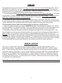
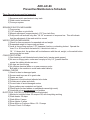
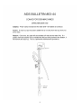
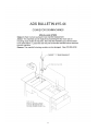
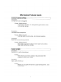
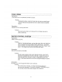
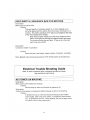
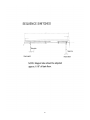
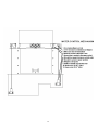
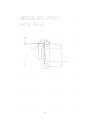
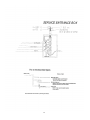
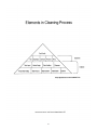
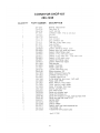
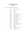
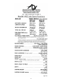
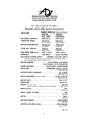
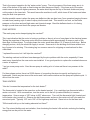
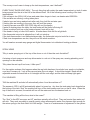
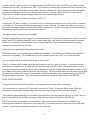
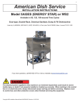
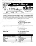
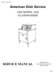
Effective Date: October 7, 2013 American Dish Service MODELS ADC44 & ADC66 CONVEYOR DISHWASHERS SERVICE MANUAL 900 Blake Street Edwardsville, Kansas 66111 (913)-422-3700 IMPORTANT: American Dish Service provides this information as a service to our customers. Keep all instructions for future reference. Although ADS will make every effort to make sure the information in this service manual is correct and up-to-date, ADS does not certify that this is the case, and should you decide to utilize this manual, you do so at your own risk. ADS reserves the right to alter or update this information at any time with out notice. Should you desire to make sure that you have the most up-to-date information, we would direct you to the appropriate document on our web site: www.americandish.com. The instructions and guidelines in this owners manual are given with the assumption that the dishwasher has been installed, operated, and maintained properly and in accordance with all applicable Codes, Ordinances, and Safety requirements. Failure to install, operate, and maintain the machine in this manner will void the ADS Warranty. ADS assumes no liability or control over the installation, maintenance (service), or operation of the equipment. Product failure due to improper installation, maintenance, and operation is not covered under the ADS Warranty. WARNING: During the operation of all dishmachines, chemicals, high voltage electricity, and normal operational functions can cause harm, bodily injury, or worse if proper installation, operation, and maintenance are not observed. It is imperative that the operator(s) are trained in the operation and made aware of the hazards that can exist. This is the responsibilty of the owner of this equipment. When installing, operating, or maintaining your dishwasher you must follow all applicable safety requirements, including the wearing of approved personal protective equipment. 2 Table of Contents Page Description 4………........ NSF Data Plate 5………........ Installation Instructions 6………........ Dishtable Requirements 7………........ Dispensers 8………........ Machine Operation 9………........ Motors 9..……........ Motor Replacement 10………...... Hi Temp Design 11…............. Preventive Maintenance 21………...... Conveyor Basic Requirements 22…….......... Conveyor Warranty Statement 23…….......... Bulletins, “Most Common Problems” 36…............. Troubleshooting Guide ILLUSTRATIONS 45………...... Sequence Switches (Tray Track) 46………...... Water Control (“floats”) 47………...... Spray Arm End Cap 48………...... Service Drop for Electrical Power 49………...... Elements of Cleaning Process PARTS 50………...... Parts Kits SPECIFICATIONS 53………...... Specification Sheet for 44” 54………...... Specification Sheet for 66” 55………...... Phase Specification, 1 phase 56………...... Phase Specification, 3 phase 57………...... Drawing Sheet for 44” 58………...... Drawing Sheet for 66” 59………...... Loader (soil table) Option 60................. Control Box, 1 phase 61................. Control Box, 3 phase 62................. Control Box for 66” 63................. FAQ Conveyor List 3 ADC-44/-66 COMMERCIAL RACK CONVEYOR DISHMACHINE MANUFACTURED BY AMERICAN DISH SERVICE NSF DATA PLATE NSF Operational Requirements for MODEL ADC-44, Multi-tank, Rack Conveyor Dishmachine as Manufactured by AMERICAN DISH SERVICE Hot Water Sanitizing Final sanitizing rinse minimum temperature: 180° F Pumped rinse tank minimum temperature: 160° F Wash tank minimum temperature: 150° F Final rinse minimum pressure: 20 psi Maximum conveyor speed: 6.8 ft./min. Chemical Sanitizing Final rinse minimum temperature: 120° F Pumped rinse tank minimum temperature: 120° F Wash tank minimum temperature: 140° F Final rinse minimum pressure: 20 psi Sanitizer required: 50 ppm available chlorine Maximum conveyor speed: 6.8 ft./min. Listing date 2/19/97 NSF DATA PLATE NSF Operational Requirements for MODEL ADC-66, Multi-tank, Rack Conveyor Dishmachine as Manufactured by AMERICAN DISH SERVICE Hot Water Sanitizing Final sanitizing rinse minimum temperature: 180° F Pumped rinse tank minimum temperature: 160° F Wash tank minimum temperature: 150° F Final rinse minimum pressure: 20 psi Maximum conveyor speed: 6.8 ft./min. Chemical sanitizing Final rinse minimum temperature: 120° F Pumped rinse tank minimum temperature: 120° F Wash tank minimum temperature: 140° F Final rinse minimum pressure: 20 psi Sanitizer required: 50 ppm available chlorine Maximum conveyor speed: 6.8 ft./min. Listing date 6/15/99 4 INSTALLATION INSTRUCTIONS SEE INSTALLATION MANUAL 5 TABLES The greatest source of service calls for conveyor accounts come from incorrect table application. Not all table types are suitable for conveyors. An existing conveyor may have improper tables. The conveyor has no doors and must operate with either side open. Tables are needed to control water flow. Water loss problems are due to improper tables and the placement of sinks and drains. 1. It is recommended that sinks and drains be a minimum of 20” from the edge of the table lip. No drains in clean table. If a drain is closer than 20” it must be removed or a new table installed. These close-sink tables are for door-type equipment and harm the operation of conveyors. This is best considered before the installation during an account survey. 2. The tables must slant toward the machine so water can return to the tanks. Otherwise, the water will be lost and the machine’s design for self-scrapping will be canceled out. This will also cause the auto-fill to activate repeatedly, thus increasing water and chemical usage and robbing final rinse pressure. The economical answer: tables are made to serve the machine, not the reverse. 3. When the tables are finally put in place, ANCHOR the table to the dishmachine using the 1/4” -20 SS hex bolts supplied in the machine package. There is a diagram for the position of the bolts along with two new drill bits. This is important, if you anchor the tables you will eliminate many service problems. 4. The table lip should not extend down into the machine far enough to rub on the conveyor bar. If this should happen cut a half-round in the table lip above the conveyor bar for clearance and fasten down the table securely on the machine. There should be no space between the table and the machine’s lip. Reason: If the elevation of the table were raised above the level of the tank lip, then the geometry of the conveyor dogs, switches, and racks will be changed. To compensate for a raised table several items must be altered and adjusted. This will create a major problem for the machine’s control and conveyor systems. It is recommended that the tables be attached to the machine according to these instructions. TABLE LAYOUT A 90° exit or a “horse shoe” layout are popular ideas because of the space saved but they cause operational problems. Even with the safety clutch, the difficulty of a short table or 90° causes constant jams. In most cases the ADS table limit switch is a better solution for shutting down machine operation when racks load up on the table. Curve or “bands” installed on the clean table are a common sight, their purpose is to take square racks around the corner. Few accomplish this goal — moving racks around a corner is extremely difficult. The usual experience is after reaching ¾ of the arch, the rack sits diagonal and blocks the following rack. It must be pulled out to continue. This layout reduces a conveyor’s output to nearly that of a corner machine. RULE: The Installation is KEY to reduced service problems. 6 DISPENSERS 1. The final rinse manifold has two ports (1/8” IPS, female) provided in the mixing chamber chemical check-valves. The dispenser’s electrical connection points are provided in the control box. There are two signals. For the 44 3-phase, a 208/240v signal labeled RINSE and a 208/240v signal labeled DETERGENT. They are located in the lower left hand area of the control box, as you face the machine. The 110v CONTROL (1amp) circuit produced by the transformer does not have the capacity to run a dispenser. It is highly recommended that no device be attached to the control circuit of the machine, such as dispensers and hood fans. Use the factory provided dispenser terminals in the control box. For the 66 3-phase, a 110v signal is provided and labeled for dispenser control in the lower left hand corner of the control box, as you face it. This 110v power is available because of the neutral line and L1 of the incoming power. 2. The wash tank has a 7/8” hole provided for a chemical probe. It is located at the front of the tank adjacent to the pump filter and pump discharge manifold. There is also a 7/8” hole for the detergent inlet located in the wash section above the scrap trays on the side of the well between the wash and rinse tanks. This can be accessed behind the heater power box located in front of the rinse tank pump. 3. Do not mount the dispenser on top of the control box. 4. Secure all chemical lines and attachment points. Make sure that chemical lines do not run over the top of electrical devices or inlet plumbing. (A leaking sanitizer line can destroy the stainless cabinet and machine components). 7 MACHINE OPERATION After the machine is operational and the tables are cleared, remove all packing material (heater supports) then wash out the tanks, give attention to any installation debris left over. Now, fill the machine by turning on the master switch. The Conveyor will automatically fill with water to an operational level. IMPORTANT: Adjustment of the water diverter plate is required to fill the tanks in proper sequence. It is found inside the hood on the back wall at the top. Slotted holes allow movement side to side. The rule: make sure the rinse tank always fills last by adjusting the stream filling the rinse tank to approximately the size of a pencil. After the pump motors start, the machine will fill once more to compensate for the water used by the pumps. This is normal operation. Place a rack at the opening of the soil side of the machine and push it in until it catches on the first dog. The machine will take the rack through, operate the pumps, conveyor, heaters, final rinse and then exit the rack and shut down until another rack is put into the machine. WHAT TURNS THE MACHINE ON AND OFF The conveyor motor, wash motor and rinse motor are all sequenced by the actual dish rack. There is no timer or control unit that causes the machine to run. Everything is keyed off the dish rack. The sequence bars located in the front tray track are used to tell the machine what to do. The reed switches are normally closed (they always TURN ON THE MOTORS), when a magnet comes within ½” of the reed, it will turn OFF. When the magnet swings away from the switch, the motor turns on. NOTE: an easy way to test the reed switch is by placing a strong hand held magnet (automotive tool) next to the reed, if it turns off that means the switch is good and the problem is alignment with the machine’s bar magnet. The heaters are controlled by the thermostats and the level control switches. If there is no water in the tanks when the machine is turned on, the level control switches will turn off the heaters and open the fill solenoid. When the tanks are full the switches will shut off the water and then turn on the heaters. If the incoming water is hotter than the settings on the thermostats, the thermostats will shut the heaters down until the water temperature drops below the set point. NOTE: To increase the temperature, turn the thermostat center rod counter clock-wise. (turn left to increase temp) The dish rack acts as 1/2 of the conveyor mechanism. The center dogs pull against the ladders of each rack. If the rack or its ladder is damaged the conveyor system will work less effectively. Damaged or broken racks should be replaced. They cause problems such as racks staying in the machine or riding back a forth on the conveyor bar. Both of these problems will cause excessive water, chemicals, and energy use. The rack is 1/2 of the conveyor system. A test to see if the machine’s tray track and tables are set up right is to place a rack on the soil table then push it through the machine and on to the clean table. It should slide easily across all points. If the rack should stick between the two tray tracks, they will need to be moved wider apart. The track is attached at three points, adjust all three to maintain alignment. (Never adjust the front tray track; always make the adjustment to the rear tray track) CAUTION: Disconnect power to the machine before servicing and tag-out power. Beware of moving gear and drive arm on conveyor. Heaters will remain hot immediately after emptying of machine. Turn machine off before opening for inspection. 8 MOTORS It is recommended that pump motors be replaced as a unit. This is classified as “pump motor complete, less cover.” The reasoning is as follows: conveyors are generally placed in high volume accounts, which have little space or time for major repairs. The simplest procedure is to remove the four housing bolts, disconnected the electrical connection and replace with a new unit. This can be accomplished without extensive service knowledge and down time for the restaurant. If there is a problem with the seal, shaft, or impeller the resulting time investment could cause disruption. The performance profile of conveyors, meaning maintenance items are usually left undone, tend to produce service events of major proportion. This problem can best be managed by a little preparation. The primary events include conveyor gearbox, heater/circuit breaker, wash/rinse pumps, and damaged or broken parts. Any of these assemblies can be replaced and operations returned to normal within 30 minutes if the assemblies are readily available. ADS has kits or lists of major items and they can be purchased in assembled form. Once a replacement is speedily made, the faulty part can be returned to the shop. At the shop there is enough time and resources to effect an adequate repair; the repaired part then becomes the replacement assembly for the next event. This is the fastest way to service the high volume conveyor business. Expecting service people to repair assemblies can place an account in a down condition. It can lead to multiple-day events. All necessary resources are simply not available at the restaurant and overnighting unexpected parts can add days before they are up again. So assemblies are recommended for key areas such as conveyor drives, pump assemblies, and plumbing manifolds. 3HP MOTOR REPLACEMENT (Wash Pump) SEAL REPLACEMENT PROCEDURE 1. Turn off power to the machine. Tag-out power to the machine. Empty water from the wash tank and open petcock on wash pump motor. 2. Remove the two mounting bolts that secure motor to frame. 3. Take out the four 3/8” bolts that hold rear pump housing to the front pump cover. 4. Slide motor and rear pump housing out of the pump cover. Place the unit on the floor and open the rear access plate on the motor. 5. Disconnect the three lead wires that are attached to terminals L1, L2, and L3. Remove the conduit from the motor. 6. Remove the impeller by taking out the secure bolt. The impeller slides off the keyway. If it does not slide off easily, gently tap it from behind. Heavy blows from a hammer will damage the impeller and shaft alignment. 7. Remove the four 3/8” bolts that hold the rear pump housing to the motor. Carefully slide the housing off the motor; paying particular attention to the shaft seal. The graphite section (black face) is the part that slides on the 1.5” dia. collar that slides over the 7/8” dia. motor shaft. The ceramic section (white race) is the part that seats in the housing. Slide the graphite section off. Be careful not to crack the ceramic when the pump housing is removed from the motor. 8. To assemble, reverse the order above. If you are replacing the seal make sure the rubber boot and ceramic (white) are fully seated at the bottom of the pump housing. If the ceramic uses an “O” ring instead of a boot, the operation is still the same. Seat the ceramic all the way in the housing. Make sure the shaft is clean. Put the boot and ceramic section in the housing first. It will be helpful to use some hand soap or dishsoap to slide the boot with the white ceramic section into the pump housing. 9 A round wooden dowel works best for applying even pressure to seat the seal into the housing. The smooth surface will face out toward you; the grooved side will face the housing toward the motor end. Do not put grease or oil on the seal. Inspect the graphite section; make sure there are no cracks or chips on the face of the black graphite or white ceramic. Slide this black part onto the motor shaft (1.5” collar) and install the spring and retainer shield. The retainer shield is important, without it the spring steel will cut into the impeller. Place the impeller on next. The keyway and slot should be free from damage or distortion. If the shaft keyway slot is enlarged, the motor will need replacement. If the impeller is also damaged in the key slot it must be replaced. Important Note: The impeller “lock bolt” must be replaced as a new part each time the pump is disassembled. Part #098-1613 9. When the pump assembly is placed back into the pump cover, properly seat the pump gasket (“o” ring) and use some dishsoap to avoid pinching the o-ring. 1/3HP MOTOR REPLACEMENT (Rinse Pump) Same as the Wash Pump except the motor shaft attaches to an auxiliary shaft. Motor shaft diameter is 5/8” and the auxiliary shaft w/seal is 3/4” instead of 7/8.” Impeller screws on right-hand threads instead of a keyway and bolt. When setting up the auxiliary shaft, slide forward until it touches the pump cover, then back off 1/8”. This pump has an open-face impeller. 1.5HP MOTOR REPLACEMENT on ADC-66 (Power Scrapper Pump) Same as the Wash Pump except the motor shaft and seal are 5/8” diameter and the pump gasket is also an “o” ring. Impeller screws on instead of a keyway and bolt. This motor, as it is used on the 66, is always wire 220v, single phase. It is, however, the standard 1.5 hp ADS motor for low-temp machines. This pump has an open-face impeller. HI TEMP DESIGN IN CONVEYORS The term “Hi Temp” refers to the sanitation process of the dishmachine. Or, in other words, the type of process used to achieve an acceptable kill rate in bacteria. There are typically two methods, chemical or thermal sanitizing. In high temperature sanitizing, the surface of the dishware must reach a temperature of 165° F for a minimum of ten seconds. It is assumed that a minimum of 3600 HUE ensures adequate sanitization. One second of 165° F corresponds to 346.8 HUE points (although 160° F only provides 91.9 points and 140° F only 1 point); this is an ascending scale, which tops out at 165° F. This is accomplished by spraying 180° F water over the dishware during the final rinse. This elevates the surface temperature to 165° F during 10 seconds, which temperature reduces organisms by 99.999%. HUE points are also added for seconds spent in hot wash water but the value only reaches a few hundred points. This is the Heat Unit Equivalent (H.U.E.) test required for NSF certification (Reference: Mallmann, A Study of Mechanical Dishwashing, University of Michigan, 1947). The ADC conveyors are rated in both methods of sanitizing, and NSF lists these dishmachines as dual sanitizers. This means the machine design can serve in both roles without modification. The final rinse manifold will accomplish the task of applying chemical sprays or high temperature sprays with the same water consumption rates and systems. The only difference is in the type of chemical dispenser application (min. 50 ppm chlorine) or the boosted incoming hot water (min. 180° F) for final rinse. (Reference: ANSI/ NSF Standard 3, 1996) 10 ADC-44/-66 Preventive Maintenance Schedule Three General areas must be inspected 1) Sequence switch mechanism in tray track 2) Water control mechanism 3) Conveyor system SEQUENCE SWITCH MECHANISM 1) Free moving 2) 1/16” clearance on pivot bolts 3) Magnet adjustment is approximately 1/16” from tank floor 4) Pump motor will activate only after 1/8-1/4” movement of sequence bar. This will indicate that the adjustment of the reed switch is correct WATER CONTROL MECHANISM 1) Check for free movement of suspended rod and weight 2) Suspended weight is free moving and clear 3) Lever is free moving and has 1/16” clearance from box or attaching locknut. Operate the lever 10 or 20 times with the tanks full, it should not stick on “fill.” If it does stick, the problem will be interference with the rod, weight, or the switch button spring may be too weak. CONVEYOR SYSTEM 1) Cam bearing is well-lubricated and rotates freely (marine grade grease) 2) No worn or sloppy parts, rocker arm free play is only 1/8”, greater than this means the rubbing blocks are worn 3) All dogs are free moving 4) No chlorine chemical leaks on or near conveyor motor Bolt table to the machine to avoid leaks under table lip NORMAL CHECKS 1) Check for bent or damaged parts 2) Screens and trays are all in good order 3) Drains are clear 4) Dispenser is functional and adjusted w/no leaks 5) Curtains are in place and clean 6) Correct leaks to avoid damaged motors 7) Spray patterns are consistent and typical 8) Check racks (broken ladders or swaybacks cause high costs) 9) Lime build-up on any conveyor is a problem ELECTRICAL CHECKS (by qualified electrical technician) 1) Machine’s total amp draw: 52 amps at 3Ø, with everything working 2) Wash heater: 30 amps 3) Wash Motor: 8 amps 4) Rinse Heater: 6 amps 5) Rinse Motor or Conveyor Motor: 0.5-1.0 amps 6) Control Circuit: 0.65 amps 11 AMERICAN DISH SERVICE TECHNICAL SUPPORT MATERIAL Routine and Preventative Maintenance BURNED WIRES Burned wires on a high amperage circuit, occurs when that circuit experiences interference with the transfer of electrons across conductors, connections, points, or terminals. When it is difficult for electricity to pass over or through a material, that restricted flow will heat up the surrounding material. This flow restriction is called resistance; you experience this when you slide across a hard wood floor on your knees. Resistance causes heat. This is an elemental problem that does not have a variety of solutions. There really is only one solution when electricity is involved: replacement of the damaged parts (including the wires) and clean, tight connections restored. If the wires or connections keep burning, it only means there is still resistance in the circuit. The burnt evidence is always within inches of the resistance problem, if not directly in the middle. --Russell Payzant 12 AMERICAN DISH SERVICE TECHNICAL SUPPORT MATERIAL Routine and Preventative Maintenance Motor Failure Items to inspect to determine the cause of a motor failure: The size wire feeding the machine, are there different sizes used in the distance to the machine. Size breaker for the machine, will it cycle on and off. Is it a new breaker. Is it a clean circuit, no other machines, lights, or motors on this dishmachine circuit. Condition of the wire, are all the strands used, are they clean, bright, tight. What is the actual voltage under load. Does it vary during the work period. 98 volts would be an operational problem, 102 volts would cause premature failures for a 120v motor. Are the flag wire connectors tight on the spades of the motor itself. Is the “crimp” on the copper or the plastic or partial. When it goes “out” did it just stop, does it hum, does it try to turn, will it run momentarily. Can you smell burning insulation--hot plastic smell The answers to these questions are pathways to determining causes for failure. A motor is a electro-mechanical machine, a failure can be the result of part failure, part damage, improper assembly, improper power supply, compromised supply devices, improper connections to power, poor quality or corrupted power (such as hot summer days in large cities). Rule for Motors—Sound motor/pump, clean adequate voltage, correct wires, sound switches and contactors, tight connections, with these 5 elements the motor is going to move as rated. If the motor does not move, the problem will be found in one or more of the 5 elements above. --Russell Payzant 13 AMERICAN DISH SERVICE TECHNICAL SUPPORT MATERIAL Routine and Preventative Maintenance POOR or NO HEATING OF WASH TANK ADC 44 Conveyor (11 gallon wash tank) The 12 kW, 208v wash heater in an ADC 44 would normally draw 34 amps on each leg. The factory setting of the thermostat is “on” at 161°F, “off” at 165°F. However, the NSF minimum temperature for the wash tank is 150°F on a multiple tank conveyor (ADC-44/66), so it is permitted to operate at 150°F in high temp sanitizing mode. The ADS thermostat is adjustable from 100°F below zero to 500°F above zero. To turn it all the way up (left turns) would be a large error. The stirred tank principle (meaning unless stirred the column of water will have differing levels of temperature) is common to any tank of water. For the ADC 44, after running 3 to 5 racks, the water then equalizes after heating the pipes, pump, and walls of the machine. NOTE: with a tank sitting and idling on the thermostat set point (161°F), the water in the sump and pump will actually only be 90 -100°F. When mixed, this cooler water commonly drops the tank temp on start up. This is true of any dishwasher; all water below the heater will remain lower in temperature. Once all the water temps are mixed, the tank heater will begin to heat until all water reaches the set point. We should not set the temperature at 170°F in the tank trying to compensate for this start up drop. Those first racks hit with that high temperature will bake the starch on and results will suffer. Keep the factory set point, check for disturbances, and follow installation instructions. After start up, tank temperature will equalize if “disturbances” to the energy transfer process are not in excess of the watts available. When the disturbances increase the cooling effect beyond the potential of the watts, temperature drops. Spraying water out of a jet will have the greatest cooling effect on tank temperature. It is a physical property of water being forced into the air through a jet; thermal energy is transferred from the water because of evaporation. Points about Disturbances 1. Low voltage to the heater—size heater kW according to available voltage. Volts are directly related to watts. 2. Poor heater—check amps, look for water mineral build up on element (1/16 thick can reduce effectiveness), look for burned elements 3. Filling during washing—table problems, sink problems. This turns off the heater. 4. Too much suction from HVAC—values about 400 cfm will draw air through the machine causing greater evaporation. 5. Fans blowing on the employees also blow on or through the machine—point fans away from the machine 14 6. Curtains missing or open—replace curtains. Long curtains are placed on the ends. The conveyor is an open process because of the two openings; this allows greater disturbance to the energy transfer. 7. Racks washing large trays—trays will divert water out of its tank 8. Washing plastic trays—plastic will act as a heat absorber. Do not wash large plastic trays rack to rack, alternate with glasses, silverware racks so heat is not totally drained out of the water. 9. Racks over loaded with too many ceramic plates become a heatsink—space out plates properly 10. Not pre-rinsing the ceramic plates and other ware with hot water means they enter the machine at room temperature or cooler and tamp down the tank temperature—especially true in the fall or winter months. 11. Finally, individual accounts may have disturbances that are not commonly seen. Everything takes heat away from water, the only way to replace it is with wattage. Even if all eleven points in this ADS heating guide are addressed, nothing will change the fact that an idle water tank heated to a set temperature, when the pump first starts spraying, will not be able to equalize the layers of water temperature for several minutes. The same is true of an electric grill, which has much better heat transfer from element to metal than from element to liquid. It still takes time for the entire grill to equalize in temperature when first turned on, it is not instant. We don’t trivialize this or dismiss it, but it is a reality we must live with. All manufacturers of commercial dishmachines (that have a holding tank with a sustainer heater) experience a drop in temperature when the tank is first stirred. Depending on conditions at the account, once the machine is used in a continuous manner, the temperatures will equalize around the set-point. If, under normal use, this does not happen there may be one of the eleven points missing, as noted in our guide. This is unless they are washing racks of plastic trays back to back, in which case the curtains are pushed open and the plastic draws off all sustaining temperatures. Nothing can be done to prevent this except to space out the racks of plastic trays with other racks of dishware. ADC 66 Conveyor An 18 kW heater will draw 44.7 amps on each leg on 208v and put 16.1 kW in the water. On 200volts it will be 42.9 amps and only put 14.8 kW in the water. The wash motor will be drawing about 8 amps each leg on 208v. Test each leg on the heater and motor and compare to those rates above. If both are lower amps than 44.7 or 8 respectively, then the tester needs calibration. If the heater is in the 30ish amp range and your motor is at 8 amps, then that will indicate there is a problem with the 18 kW heater, or it is a 12 kW or 14 kW by mistake. If the machine is refilling during operations it will be caused by a weakened float switch (replace), poor racking procedure (training), table problems (sink too close to machine), or spray arms not in position or jets are bent spraying into other tanks (training). --Russell Payzant 7/2013 15 AMERICAN DISH SERVICE TECHNICAL SUPPORT MATERIAL Preventative Maintenance QUESTIONS TO EVALUATE OPERATION OF CONVEYOR MACHINES 1. Will the machine fill with water when it is turned on for the first time during a new work period? If it does not fill, is the “ON” light illuminated when the master switch is turned on? If not, the machine will need electrical service. [SERVICE ITEM] 2. When the machine fills with water, what is the incoming water temperature? It should be 120°F for Chemical Sanitizing and 160°F for Hot Water Sanitizing. This requirement is supplied by the building’s primary water heating source. [BUILDING MAINTENANCE] 3. After the machine has filled with water, a rack of dishes can be pushed into the machine on the “soil table” side. The wash pump and the conveyor should begin operation. If they do not, look at the inspection door, is it fully closed? Look at the table limit switch (if one is being used); is a rack or other item pushing on the switch activator? These switches must be closed (meaning not activated) for the operation to begin. [OPERATOR ERROR] 4. Does the machine continually fill, causing the primary water-heating source to run out of hot water? This condition will be a result of water escaping from one or both of the tanks: The rinse tank is likely to pump out water via a bent deflector fin on the pumped rinse spray arm. This can be remedied by bending the fin back in line, so that the sprays are falling straight down and pumping straight up (12:00 o’clock & 6:00 o’clock). This problem most often occurs as a result of striking the spray arm against a table or trash can to clear soil stuck in the arm. [OPERATOR ERROR] For the wash tank, the likely cause will be water cascading out on the soil-table. This is remedied by correct installation of the tables. The scrap sink must be no closer to the entrance of the machine than 20 inches; and the tables must pitch into the machine so that water flow on the table surface will return to the machine. Quick drains or table scuppers are not used on “stage washers.” [INSTALLATION ERRORS] NOTE: The auto-fill feature should not operate during normal use, its only operation is at the first of the shift when the machine is off and empty. Intermediate filling is an indication of installation problems. 5. Is the final rinse water at the correct temperature? 120°F min. for Chemical, and 180°F min. for High Temp. The correct final rinse temperature is critical to operational temperature. [BUILDING MAINTENANCE] 6. When the last rack exits the machine, will the conveyor and final rinse shut down? If not, open the inspection door and check the rack guide sequence switches (magnet bars, which hang down from the rack guide). Look for a glass or bowl that may be obstructing the bar and keeping it from hanging straight down (at 6:00 o’clock). [OPERATOR ERROR] 16 7. If a surging sound is coming from the wash pump, check the pump filter and tank trays. They may be filled with debris. Clean the filters and trays, refill the machine. [OPERATOR ERROR] 8. When racks do not travel completely through the machine, examine the bottom of all the dishracks. If the “ladder” bars are missing or broken, the rack must not be used. The dishrack is part of the conveyor system and must be intact and complete. [OPERATOR ERROR] 9. Chemical supply is provided by the chemical company. [SERVICE ITEM] 10. The curtains must be in good repair and properly placed in the machine to retain temperature in the wash environment. If the curtains were left out, the air would circulate through the machine and rapidly cool the water sprays. [OPERATOR ERROR] 11. Dish and glass appearance is often referred to as “results.” If the results are poor, there are several factors which affect the outcome of the washing process. First is procedure. If the dishes are not placed so the sprays can reach them, the results will be poor. If large amounts of soil are left on dishware, this will eventually overwhelm the process (any size tank can be overfilled). Second is temperature and water condition. If water temperature is too low or too high it will cause problems. Hard water with high mineral levels will build up a white substance in the watered areas of the machine. A 1/16” layer of build-up on the surface of a heater element will reduce its efficiency by twenty percent (that’s like turning a 10kw heater into an 8kw). If there are scale producing elements such as TDS, carbonates, silicates, calcium, sodium, other minerals or chemicals— results will suffer. This is especially true of well water. A good test for poor water conditions is to take clean glasses, hand buff them, turn off all chemical feeders, wash the glasses 4 or 5 times in clear water in the machine. If they come out spotty or cloudy, you have a water problem not a machine or chemical problem. It is important to treat hard water before it is used in conveyor equipment. [BUILDING MAINTENANCE] Third, installation problems are the # 1 cause of operational disruptions and will affect performance. If the machine is improperly installed no amount of tuning or adjustment can compensate for the lack of essential process elements. The installer must return and correct the omitted elements of the installation. 12. Check tightness of wire connections on all high amp draw terminals. These are identified as heater connections. Disconnect power to the machine first. Check main distribution block, circuit breaker, contactor, heater terminals. Check all screw terminals with a screwdriver, should be hand tight. This will take less than a minute to perform but pay high dividends over the service life of the machine. [SERVICE ITEM] 17 AMERICAN DISH SERVICE TECHNICAL SUPPORT MATERIAL Preventative Maintenance Replacement of ½” water solenoid diaphragm Solenoid valve assembly Remove screw and coil from tube Twist to remove top, RH threads, first close water pressure to valve then twist top Correct plunger placement, spring on top Coil will lift plunger in the tube. 18 Inspect the gasket in bottom of the plunger It must seal the top of the rivet shown here Turn over the diaphragm inspect near the rivet head A cut or indent would stop sealing on the center ring Remove the o-ring retainer, remove the screen Remove any material or debris from the body. Inspect the center ring for cuts or damage to the surface. If the stainless seat (center ring ) is rough or cut, the valve body must be replaced. Reassemble in reverse order 19 Failure modes Errors are returning a corroded diaphragm to service. Failing to remove spring lodged in tube Installing valve wrong way, see arrow flow direction Installing diaphragm upside down, see lettering up Failure to notice indents at sealing ring If voltage is at the coil but plunger will not lift, bad coil 4/29/2013 20 Conveyor Minimum Basic Requirements 1) Table with less then two racks “out” is not recommended. 2) A 90° curved table on the exit side is not recommended unless it is over five racks distance (100”) from the machine. 3) The minimum distance a sink or drain device can be to the entrance side (soil) of the conveyor is 20”. And no such device should be on the clean side. 4) Less then five racks out should have a limit switch installed on the exit table. 5) Incoming rinse water shall be rated 120F at 120 GPH. Or 180F at 120 GPH. 6) Electrical wire supply shall be 6 gauge, 3 ph, 208v at 60 amp clean circuit. Single phase 208v, one 60 amp/6AWG service and one 50 amp/8AWG service with a Neutral (10 AWG) and suitable ground. ADC-66 is 3 gauge, 3 ph, 208v at 90 amps. 7) Tables to be bolted to the machine on clean and soil sides as noted in installation sheet and manual. 8) Do not install chemical dispenser on top of control box or run chemical tubing over critical areas of the machine top: plumbing, electrical boxes. 9) Do not install with 180° turn in the drain pipe. Make short runs and eliminate tight 90° elbows when possible. 10) Adjust the tables to meet the machine. Do not adjust the tray track to meet an ill-formed table, fix the table. Tables must be slanted toward the machine; 0.5” drop over 70” of travel as a min. 21 AMERICAN DISH SERVICE Limited Warranty Parts and Labor American Dish Service warrants to the original purchaser that its products are free of defects in material and workmanship and agrees to repair or replace, at its option, any parts that prove to be defective within ninety (90) days from date of purchase. American Dish Service may require reasonable proof of your date of purchase. Therefore, you should retain your copy of the invoice or shipping document. In addition, American Dish Service will exchange any part covered under this limited warranty which is found defective, as determined by American Dish Service, under normal use and service up to two hundred and seventy (270) days following the first ninety (90) day limited warranty period as described above, excluding feed line, flexible hose, and squeeze tubes. The warranty does not cover equipment subject to accidents, freight damage, improper power and/or plumbing hookups, or lack of routine required maintenance as determined by American Dish Service. This warranty is void if the defect is due to improper installation, high chemical concentrations, misuse, modification of the machine, repair or servicing other than by an authorized American Dish Service dealer, or authorized agent, or operated in a manner contrary to applicable factory instructions herein or failure to perform all required maintenance. The timer cams for water and chemicals are adjustable. Proper adjustment is the responsibility of the installer of the equipment. This warranty does not extend to machine malfunction resulting from improper cam adjustment. All warranty work for machines will be performed, within the ninety (90) day period, during normal working hours, by an authorized agent receiving prior authorization by American Dish Service. Overtime charges and expediting charges such as “overnight” and “air freight” will be the responsibility of those requesting service outside normal American Dish Service procedures. Expenses due to disconnections, delivering, returning, and reinstalling the machine are borne by the purchaser and are not the responsibility of American Dish Service. Travel charges for time and mileage outside normal service area (75 miles) shall be the responsibility of those requesting service. Defective parts become the property of American Dish Service. Parts replaced within the warranty period carry warranty only until the end of the original limited warranty. Replacement parts not supplied by American Dish Service will relieve American Dish Service of all future liability and responsibility. American Dish Service will provide the names of the nearest authorized dealers upon request. ADS is not responsible nor liable for any conditions of erosion or corrosion caused by corrosive detergents, acids, lye or other chemicals used in the washing or cleaning process. This warranty is void outside of the United States of America. AMERICAN DISH SERVICE HAS MADE NO WARRANTIES THAT THE GOODS SOLD OR SERVICES PROVIDED ARE MERCHANTABLE OR FIT FOR ANY PARTICULAR PURPOSE AND THERE ARE NO WARRANTIES, EXPRESS OR IMPLIED WHICH EXTEND BEYOND THE EXPRESS LIMITED WARRANTY CONTAINED IN THIS AGREEMENT. UNDER NO CIRCUMSTANCES SHALL AMERICAN DISH SERVICE BE LIABLE FOR ANY LOST SALES, LOST PROFITS OR ANY OTHER INTANGIBLE LOSS OR ANY OTHER SPECIAL OR CONSEQUENTIAL DAMAGES ARISING OUT OF THE USE OR ANY INABILITY TO USE THE PRODUCTS SOLD BY AMERICAN DISH SERVICE. American Dish Service’s liability under this agreement shall in no event exceed the amount paid for the equipment purchased from American Dish Service. This warranty will be void if the Warranty Registration Card is not returned to American Dish Service within 30 days of the equipments installation. This warranty is void if the equipment is installed for residentuial use. Any action under the terms of this Warranty must be commenced within one year from the date of purchase of the equipment. 22 COMMON SERVICE PROBLEMS ADS BULLETIN #02-44 Effective Date 8/94 Rack travel and counting with a timer in CONVEYORS Rack-style conveyors move dishracks across the sprays by the reciprocation of articulating dogs. These dogs push in one direction and fold down in the return direction. They push against the “ladder” on the underside of the dishracks. The “speed” of NSF listed conveyor dishmachines is determined by the length of time required for a Metro G-88 glassrack to travel across from the soil table to the clean table. The starting and ending point is the table lip. The indicating point is the trailing edge of the rack. If it takes 36 seconds to cross this distance the rated speed will be 6 feet per minute. The speed is determined by two items: the action of the conveyor dogs and the placement of bars on the rack ladder. If either of these are missing or damaged the speed will drop. If too many ladder bars are missing the rack will not travel through the machine. In actuality, the rack is responsible for 50% of the conveyor’s speed mechanism. Racks other than the Metro G-88 glass rack will cause some variations in the speed. The ADC-44 uses ten dogs to reduce this variation and give more consistent output. If a clock timer is installed to act as a rack counter it can only record the amount of time the machine is operational. It can not sense an actual rack. It can, however, accurately record the amount of time the machine uses chemicals and energy. By estimating the number of potential racks the conveyor is capable of processing you can arrive at an approximation. Fortunately, the ADC design operates only when a rack is present and shuts down mechanically when the rack exits. This will give closer rack figures then other styles of conveyor control devices. If there is an inaccuracy in the overall count, it will be less actual racks washed then the multiplied figure. Note: while the actual rack count may be less, the amount of chemicals, water and energy (over time) will be correct. 23 24 25 26 27 28 29 30 31 32 33 34 35 36 37 38 39 40 41 42 43 44 45 46 47 48 49 50 51 52 53 54 55 56 57 58 59 ADC-44 Conveyor 120V CONTROL CIR. GN L2 L1 MASTER SWITCH 120V TERM. BARS BLACK FINAL RINSE RELAY WHITE DOOR SW PURPLE BLUE BLACK RINSE REED SW BLUE BROWN BLUE RINSE RELAY WASH REED SW RED BROWN RED BLACK WHITE WASH RELAY WHITE FILL SOLENOID WASH TANK FLOAT SW BLACK WHITE ORANGE FINAL RINSE SOLENOID RINSE TANK FLOAT SW BLACK YELLOW OVERLOAD RINSE MOTOR WHITE MOTOR CONTACTOR RINSE DETER DISP HOOKUP BROWN OVERLOAD CONVEYOR MOTOR (Slave Contacts) MOTOR CONTACTOR RED HOOD FAN (OPTION) N/O CONTACT SWITCH OVERLOAD WASH MOTOR YELLOW MOTOR CONTACTOR Thermostat Relay RINSE TANK SUSTAINER HEATER THERMOSTAT TANK HEATER CONTACTOR 2.25 KW Thermostat Relay WASH TANK SUSTAINER HEATER THERMOSTAT TANK HEATER CONTACTOR HEATER CIR. BRK. 60 ADC-44 Conveyor for 3-phase, 208-240v power 120V CONTROL CIR. GN L3 L2 L1 MASTER SWITCH 120V TERM. BARS TRANSFORMER BLACK WHITE POWER CONNECTION FINAL RINSE RELAY DOOR SW 60 AMP, 6 AWG WIRES III PHASE, 60 HZ PURPLE CLEAN CIRCUIT REQ. BLUE PLUS GROUND WIRE BLACK RINSE REED SW BLUE BROWN 240V HIGH LEG ON L3 BLUE RINSE RELAY WASH REED SW RED BROWN RED BLACK WHITE WASH RELAY WHITE FILL SOLENOID WASH TANK FLOAT SW BLACK WHITE ORANGE FINAL RINSE SOLENOID RINSE TANK FLOAT SW BLACK YELLOW OVERLOAD RINSE MOTOR 1/3 HP, 1 AMP 2.8, 3.9, 1.7 (4, 5, 6) WHITE MOTOR CONTACTOR RINSE DETER DISP HOOKUP BROWN OVERLOAD CONVEYOR MOTOR 1/3 HP, 1 AMP (Slave Contacts) MOTOR CONTACTOR RED N/O CONTACT SWITCH OVERLOAD WASH MOTOR 3HP, 8 AMPS YELLOW MOTOR CONTACTOR Thermostat Relay 50 AMP HEATER CIR. BRK. 2.8, 3.9, 1.7 (4, 5, 6) HOOD FAN (OPTION) RINSE TANK SUSTAINER HEATER THERMOSTAT TANK HEATER CONTACTOR 2.25 KW Thermostat Relay WASH TANK SUSTAINER HEATER THERMOSTAT TANK HEATER CONTACTOR 61 12 KW, 33 A @ 220v ADC-66 Conveyor for 3-phase, 208-240v power 120V CONTROL CIR. GN L3 L2 L1 MASTER SWITCH 120V TERM. BARS BLACK FINAL RINSE RELAY WHITE POWER CONNECTION 90 AMP, 3 AWG WIRES III PHASE, 60 HZ CLEAN CIRCUIT REQ. PLUS GROUND WIRE DOOR SW PURPLE BLUE BLACK RINSE N/C REED SW BLUE BROWN 240V HIGH LEG GOES ON L3 BLUE RINSE RELAY WASH N/C REED SW RED BROWN WHITE BLACK RED WASH RELAY BLACK SCRAP N/C BASKET N/O REED SW REED SW BROWN WHITE SCRAPPER RELAY BLACK WHITE FILL SOLENOID WASH TANK FLOAT SW BLACK WHITE ORANGE FINAL RINSE SOLENOID RINSE TANK FLOAT SW BLACK YELLOW BLACK POWER SCRAPPER MOTOR OVERLOAD WHITE 1.5 HP, 7.5 AMPS, I PH MOTOR CONTACTOR OVERLOAD RINSE MOTOR 1/3 HP, 1 AMP 2.8 3.9 1.7 (4, 5, 6) WHITE MOTOR CONTACTOR RINSE DETER DISP HOOKUP BROWN OVERLOAD CONVEYOR MOTOR (Slave Contacts) MOTOR CONTACTOR RED N/O CONTACT SWITCH OVERLOAD WASH MOTOR 3 HP, 8 AMPS YELLOW MOTOR CONTACTOR Thermostat Relay BROWN 20 AMP HEATER CIR. BRK. 1/3 HP, 1 AMP 2.8 3.9 1.7 (4, 5, 6) HOOD FAN (OPTION) RINSE TANK SUSTAINER HEATER THERMOSTAT 2.25 KW, 6 AMPS TANK HEATER CONTACTOR BROWN 2.25 KW Thermostat Relay WASH TANK SUSTAINER HEATER 60 AMP HEATER CIR. BRK. THERMOSTAT TANK HEATER CONTACTOR BLACK 62 18 KW, 48 AMPS Frequently Asked Questions (ADS Conveyor & High Temp Dishmachines) “What is the dishmachine’s operation—how does it work?” Operation: Be sure all the screen filters, drain stoppers, spray arms, and curtains are put in their correct place. Turn on the master switch located on the side of the control box. The machine will fill automatically. Prepare a rack of soiled dishes and push the rack into the machine. The conveyor will start automatically and push the rack through the wash and rinse sections then exit the other side. The HT-25 single rack door machine will start when you close the door. The HT-25 will begin a timed wash cycle, the wash motor stops and the final rinse solenoid will spray clean heated water for 10-seconds, ending when the indicator lights turn off. Installation Errors Installation errors account for a high percentage of all service calls and questions. Please refer to the ADS Installation Instructions for specific models. These documents are available on-line at (www.americandish.com) and also come with each new machine. They can be emailed or faxed during normal working hours. Electrical requirements, plumbing needs, control adjustments, cautions, and start up information are contained in the Installation Instructions. Category 1, ELECTRICAL WIRING ISSUES “Why did the wire burn at its connection?” A burned wire with black or green colored copper and the insulation melted back an inch or two indicates a loose connection, looseness creates resistance, electrical resistance produces heat. Over time this heat will melt and char plastic insulation. The heating source will be located at the end of the burned wire or the connection point. A burned wire can also come from a shorted switch that causes the same resistance as a loose connection. “What size wire should I use to power the machine?” The manufacturer recommends NEC wire codes--or better. For a 208v, 60-amp machine, minimum 6 gauge wire is recommended. “Can you use a fuse instead of circuit breakers?” Yes, as long as it is a 60-amp fuse for a 44-inch conveyor III-phase, 90-amp for a 66-inch conveyor three-phase, or 50-amp for an HT-25, three-phase w/ booster. See Installation Instructions for single-phase equipment. “Can the machine be plugged into an outlet like a household dryer?” The answer is no. According to electrical code, 60 amp service needs to be connected and hard-wired using screw/terminals to its own circuit breaker. Further, Underwriters Laboratory and building code require the circuit breaker to be clearly labeled “dishwasher.” 63 “Why does the circuit breaker keep tripping after the machine runs for a while?” Circuit breakers become weaker as they are repeatedly tripped or if they are hit by an unusually strong short. Consequently, a breaker can begin ‘nuisance tripping’ and should be replaced. Another cause can be a motor or heater that is getting ready to fail. Wires that have melted and allow current carrying load to come close to the neutral or other phase will trip a breaker. (To verify, take the wires out and separate them. If they are stuck together that means they have melted and should be replaced.) When copper burns, microscopically the metal becomes porous and has more resistance than solid wire—and will burn again. “Why does the circuit breaker trip as soon as I turn on the machine?” This usually indicates a serious short, a grounded circuit, or a crossed phase. For a 60 amp breaker to trip so violently would indicate a powerful contact such as a grounded motor or solid connection to neutral has occurred. “Machine runs on all the time, why?” HT-25: Lift the door to see if it will stop. If it does NOT stop, the problem is a faulty door switch. If it does stop, the problem is likely the ‘Auto-start” relay. You can test by removing the yellow wire for terminal #1 and run a cycle. If the machine turns off normally at the end of the cycle, the problem is a faulty relay and should be replaced (P/N 091-3059). A failed “start” push button, de-lime switch, or the master (on/off) switch on the cam timer can also cause this problem. CONVEYORS: If the machine continues to run after racks have exited the machine, the likely cause is a stuck or failed tray-track REED SWITCH. These are located just outside and under the wash and rinse tanks. The magnet that is attached to the tray track and is suspended from the front rail hangs directly over each reed switch. The switch is “normally closed” and the magnet’s influence is the only thing that will turn off the conveyor and pumps. ADS provides wire diagrams on the various models for troubleshooting electrical problems. Go to www.americandish.com to download technical and electrical diagrams. Category 2. MACHINE FUNCTION ISSUES PUMP PROBLEMS “Why is the pump filter being clogged with string fiber?” Historically string fiber in the pump filter comes from washing mop heads and bus towels in the dishwasher. However, this practice introduces floor bacteria to the internal parts of the machine and is difficult to remove with out complete disassembly. These kinds of bacteria and soils cause sickness and can be deposited on clean ware. Operators should be warned to not use the dishwasher in this way. It also creates mechanical problems in manifold, seals and spray arm systems. “The pumped rinse sprays are only coming up 6” on the bottom and not rinsing the inside of the glasses?” 64 That is the correct operation for the “water-curtain” pump. The only purpose of the lower spray arm is to rinse off the bottom of the rack so final rinsing can take place more easily. If the lower arm of the water curtain were to spray with higher pressures, the water would layover the top of the tank divider and pump out the water in the rinse tank. This would cause the machine to re-fill, which turns off the heater and takes away the final rinse pressure. Another possible cause is when the spray arm deflectors tabs are bent over (from operators banging the arm on trash cans) causing a jet of water to spray into the wash tank. This results in no heat, no final rinse pressure on the clean end and high water and chemical usage. Bend the deflector back so it is facing straight up and down and check the sprays are likewise. PUMP MOTORS “The wash pump motor keeps tripping the overload?” This is an indication that the motor is having a problem or there is a loss of one phase in the electrical power. Testing the amp draw of the pump motor should run balanced with approximately 8 amps on each of the three legs for three-phase. For single-phase the motor would draw about 12-15 amps on both legs. Before changing motors, verify the electrical supply is correct. Some work in the building could have caused one leg of power to be missing. This missing leg is a common cause for a tripping an overload and is often overlooked. “I replaced the motor, but it still trips the overload?” The existing overload could have been damaged by the prior problem with the motor, especially if it was reset many times before the new motor was installed. It is a good practice to replace the overload whenever a motor is replaced. “I put on a new pump motor. Now the new pump is making a lot of noise and there is no pressure in the wash?” For three-phase motors, there is a 50/50 chance of connecting the wires incorrectly and having it run backwards. Switch any two wires at the motor and it will reverse rotation and the pump will operate quiet. It did not hurt the motor. TANK HEATERS “How do I increase the temperature for the tank heater?” The thermostat is located in the same box as the heater terminal. It is a cartridge type thermostat with a center rod control. With a screwdriver, turn the center rod to the left (counterclockwise) to increase temperature. It has a range of 100° below to 500° above zero. Turn until the thermostat light (located next to the heater relay) comes on. Observe the dial thermometer and move the center rod until you reach the correct set point. Typically 163°-on to 168°-off for high temp tank heat. Same is true for the rinse tank. “Will mineral build up on the heating elements hurt them?” Yes. The mineral buildup acts as insulation, thus shortening the heater’s life and also reducing the heating energy that can be put into the water. 65 “The conveyor can’t seem to keep up the tank temperatures, can it be fixed?” EVERYTHING TAKES HEAT AWAY. The only thing that will sustain the water temperature in a tank of water being sprayed into the air is the kW in the element itself. All of the following cause cooling of the tank temperatures. If the voltage is low (200v) kW is less and water takes longer to heat, use heater rated 200/208v If the curtains are missing, cooling takes place If plastic trays are being washed rack after rack, they hold the curtains open If cooling fans are running in the room, they will cool the sprays If venting fans are over 800-1200 CFM, they will cool the sprays If water is draining down the table, the tank heater will be turned off during fill If there is calcium build up on the heater element, heat will be lost If the heater is faulty, a loss of kW results. A heater has a finite life like a light bulb If the thermostat set point is adjusted low, it will not catch up If the tank thermometer is not calibrated accurately, the thermostat set point could be in error If final rinse temperatures are low, they will cool the whole machine. You will need an accurate amp gauge and digital thermometer to troubleshoot heating problems. SPRAY ARMS “Why is water spraying out of the top of the doors or out of the sides onto the tables?” A missing or bent spray arm end cap allows water to rush out of the spray arm, causing splashing out of openings on the machine. “Why does the end cap fit so loose, it falls open?” For the captive endcaps, this happens when the cap latch has been forced shut over seeds or toothpicks, over time it loosens up. Look at the cap end-wise (the coin edge). It should be straight. Bend with an adjustable wrench the small tab so it is straight with the coin edge, and the latch will snap tight again. FILL SOLENOID “Will the machine fill and shut off automatically when I turn the machine on?” The answer is YES; it will fill automatically when it is turned on. Any time the tank water level drops below the bottom of the tank “float” the machine will turn off the tank heaters and turn on the fill valve. When the top of the float is covered, the switch will turn off the water and turn the heaters back on. “The machine is filling all the time, what is the cause?” The “float” in the ADC conveyor and HT machines actually will not float. They are heavier than water and will sink. They work according to specific gravity, when submerged in water; they become light enough for the return spring in the float switch to lift the weight. There is no maintenance or adjustment to the system. 66 If there is a fault, repairs consist of #1 replacement of the ADS switch (P/N 291-3014 only, similar looking switches will not work), #2 replace the “float” or #3 removing anything that interferes with the rod holding the weight—like buildup inside the protecting tube. With the machine full, test by flipping the lever that pushes against the switch button 5-10 times, should never stick on. If it does, refer to the three repairs above. There are two switches on the conveyor, either one turns on the single fill valve. “Why won’t the machine fill with water when I turn it on?” If there is no “fill” water coming in, it can be a result of an electrical problem from a faulty switch, loose wire, or a failed coil. Test at the fill coil’s two electric wires to see if there is 115v when the machine is turned on and tanks are empty, if there is voltage, the problem is a bad coil. Or it can be a result of no water supply to the machine, check to see if the valve has been turn off. “Why does it take so long to fill the machine?” Reasons for slow filling can be clogged or undersized piping (1/2” pipe min, recommend ¾” pipe), restricted pipes, faulty PRV (pressure regulator valve), water heater type, and the facility’s water pressure problems. Tankless or on-demand water heaters are not recommended for commercial dishmachines because of restricted pressure and long fill times. “What should we do if the incoming water is too cold?” If the water heater is too far away, pipes need to be insulated. If the heater is not sized for the demand, it needs to be up graded. If it is turned down too far, it needs to be set up (120°F min at the machine). “How do I adjust the fill so all the tanks fill up on a 66 or 44?” There is a diverter plate located inside the wash cabinet, near the center at the top. It is mounted on two studs and has slotted holes. Loosen the two nuts and it can slide left or right. Place the diverter so it just interrupts the incoming water stream enough to separate a small jet of water about the size of a pencil. This jet of water will follow the plate and flow into the rinse tank. When the rinse tank is the last tank to fill up, that will mean the overflow from wash and rinse tanks will fill the last tank (power scrapper tank) of the ADC-66 before shutting off the water. This is the same procedure for setting the adjustment on the ADC-44. FINAL RINSE SOLENOID “How much pressure should be indicated on the gauge when the final rinse is spraying?” The requirement is a minimum of 20 psi and a maximum of 25 psi. Pressures that are near 30 psi will overcome most peristaltic feeders and prohibit chemical dispensing into the final rinse manifold. “The pressure gauge reads 65 psi, but when it goes into final rinse the pressure will drop to 15 psi, there is plenty of pressure in the building, why does it drop so much when connected to the ADC-44? The 65 psi is simply the building’s static pressure. That means, when all openings are closed to the building’s water pressure—the source (municipal utility), is providing that much pressure to the local water system. Like a balloon filled with air and a knot tied in the end. 67 When a tap is opened or a valve is opened, it is like taking the knot out of the balloon and all the air is forced out under pressure. This is called flow pressure, the force the balloon can expel when opened. The flow pressure is always lower than the static pressure (when the knot is closed). The larger the opening, the lower the flow pressure. When there is a significant drop in flow pressure, from static—it means the opening is large compared to the pipe (balloon) and the pressure is dissipated too quickly. When the pipe or branch line feeding the fixture is sized correctly and when it is a clean line, appropriate flows can be maintained by the utility. Quick Notes: Run ¾” or larger copper pipe supply lines to commercial conveyor dishmachines directly from the water heater. Do not branch off this line for sinks or tables. Replace old pressure regulator valves (PRV), existing booster heaters may be corroded at inlet and outlet openings, and the actual piping may be corroded inside to half its original ID. Tankless or on-demand water heaters are not recommended. “The chemical dispenser needs a signal for the final rinse; can the final rinse solenoid voltage be used to power the dispenser?” The answer is no. There are wash and rinse signal terminals provided in the control box for dispensing equipment and clearly marked with yellow decals. These are the safe sources for a signal. The fill and final rinse solenoids run off the machine’s transformer supplied control voltage. This power only has a one amp capacity, which is fully used by the machine. Using the internal 120v control voltage to power a dispenser or ventilation fan will result in machine electrical failures and can void warranty claims. Category 3. GENERAL QUESTIONS “How do I turn ‘on’ the machine?” There is a master switch located on the side of the control box. Once this has been turned on, the machine will begin to fill, if it is empty. After filling is completed (water will start flowing into the scrap box located on the soil table side) slide a dishrack into the machine to start the wash cycle. When the rack travels through the machine and exits the other side that will complete the process. “The machine did not turn on, what do I do next?” Check the circuit breaker. Push in the roller on the door switch plunger on the front inspection door of the machine. Look to see if a rack is sitting against a table limit switch on the clean table. Check the master switch to see if it will operate. If these quick answers don’t work, it will require a service call. “The Conveyor keeps running when the racks are taken out?” The cause is likely something interfering with the tray-track switches located on the front tray track. Look for a bowl or plate trapped behind the tray track, holding the suspended magnet tube away from the bottom. 68 If the magnets are hanging freely at the 6:00 position and about 1/16” off the bottom, the problem will be a faulty REED SWITCH or misalignment of both magnet and switch. Test by using a large magnet (one strong enough to pick up a screwdriver). Put it up to the reed located on the underneath side of the wash or rinse tanks near the front corners of the machine. If the machine turns off, the switch is okay and the problem will be alignment of the inside magnet and the switch mounted outside. The switches are ‘normally closed’ and different from typical reed switches used by others. CHEMICAL FEEDERS ADS Conveyors and the High Temp door machine require commercial chemical feeders or dispensers. If you are using the machine as a chemical sanitizer, that requires a three-product dispenser. If you are using the machine for high temperature sanitizing, a two-product dispenser is needed. Installation and service questions of the feeder units are referred to the manufacturer. PLUMBING DRAINS “If there is a grease trap but the machine drains are just a little higher than the trap, can it still be used to connect the dishmachine drain?” The answer is no, water only drains down hill. When this rule is not followed, it results in leaks and foul smells. “If there is a wall drain but the machine drains are just a little higher than the wall drain, can it be used to connect the dishmachine?” The answer is no, water drains down hill. For a wall drain you must install a trap to prevent sewer gas from entering the room through the pipe. This will bring your wall drain access even lower. Typical access points for drains on conveyor and high temp equipment is 8” off the floor. “The drain discharge on the machine is on the opposite side of the machine from the building drain or the building drain is under the machine, can I make a few “U” turns to reach the building drain?” NO, tight bends in piping is not recommended. The soil load will clog the drain line at the 90° elbows; straws and toothpicks create “nesting” and cause repeated service calls and flooding. Clean outs are needed if tight 90s are used in the drain plumbing. “What size drain line can I use on a conveyor or high temp door machine?” Use 2” pipe or larger. Never use reducers and always drain to larger diameter pipe. “Can I use “FLOOR SINKS” for Conveyor or HT tank drains?” Yes, but caution should be used. Make certain the drain is free running and a “deep” floor sink is used (no shallow types). When the machine is emptied, 15 gallons will come flooding out all at once. Test before you commit. 69 LEAKS “Why is water leaking out of the pump next to the motor?” It is because of a failed pump shaft seal. The next question is “But I just put a new one in.” It may have been put in dirty, facing the wrong way, or seated improperly in the housing. The seal may have been cracked or chipped prior to or during installation. Use some liquid dish soap to re-assemble, do not use grease or oil. “Why is water spraying out of the door or on to entrance and exit tables?” Check for missing or open spray arm end caps. DOOR ARM ISSUES (HT-25 only) “Why is the door hard to raise and will not stay up?” The metal door guides could be bent inward by the table causing binding on the door. Using a screwdriver, carefully pry the guide out to give adequate clearance. The door guides could be out of alignment. Adjust the rearward guides so they are parallel with the front guides. Or the door springs could be tensioned too little. Adjust the nut on both door spring eyebolts to give more tension. Caution: take the tension off the eye bolt and nut (by pulling down on the spring) before trying to turn. Otherwise it is likely to gall the stainless threads when turning the nut, this mistake usually requires cutting off the eye-bolt and nut. “Why won’t the door stay closed, it rises a little after the machine begins to run?” This means the tension on the door springs is too great and should be adjusted for less tension. Caution: take the tension off the eye bolt and nut (by pulling down on the spring) before trying to turn. Otherwise it is likely to gall the stainless threads when turning the nut, this mistake usually requires cutting off the eye-bolt and nut. “Can I disconnect one of the doors on the HT-25 so we don’t get the floor or wall wet?” The answer is NO on the door. That will cause an imbalance in the door arm. If a shield is needed for one door, ADS offers an inside shield that can be installed (# 387-6019 –splash plate). Category 4, REGULARLY PERFORMED PROCEDURES END OF SHIFT DUTIES “When I change chemical buckets, do I have to prime the lines again?” Yes. Always prime the supply so chemical is available for the next cycle. 70 “How often do I have to clean out the pump filters, spray arms, or scrap box tray?” They should be cleaned after every meal period “Does the machine need to be turned off at night?” Yes. Always turn off electrical equipment when not in use or when the facility is closed. “Can they wash their floor mats in the dishmachine?” No. The floor mats carry floor bacteria and soils into the dishmachine. This should never be done in a machine used for cleaning public eating utensils. The practice of washing floor mats or mops in a commercial dishmachine is prohibited by FDA Food Code in section 6-501.15 “Can the dishmachine be washed down during clean up?” No, it is considered electrical equipment. While it is true the inside tank can be washed out with a hose, the machine itself cannot be safely hosed down with water or sprayers. “How do I ‘de-lime’ the machine?” This treatment should ONLY BE PERFORMED BY TRAINED AUTHORIZED PERSONNEL. The addition of de-scale acids, if chlorine sanitizer is present, can produce hazardous gas. The HT-25 machine has a de-lime service switch locked inside the control box. The machine should be drained, clear water added and then the de-lime switch turned on (which only runs the pump). At this point, the acid product can be safely added to the water by pouring into the tank. Refer to the printed instructions on the bottle for dilution rates. Caution: do not let acid sit in the machine unattended or overnight. Category 5, “RESULTS,” OR WHY MY DISHES DID NOT COME OUT CLEAN? “Why are the glasses and silverware coming out with streaks and filmy appearance?” The dishmachine does not produce white liquid or grease. So, if clean heated water (120°F min) is supplied to the machine, chemicals adjusted correctly, and the five machine functions of the machine are in place (start, wash spray, heat water, convey, rinse spray) —the problems come from procedure or water conditions. Rub the glass with fingers; if the film runs or feels greasy, it is likely a build up of grease and fats. Check temperatures and detergent settings. If cloudy substance or film disappears after placing a glass half way in a bowl of delime acid, it comes from supply water minerals and must be treated separately. “Why are the glasses coming out with specs on them?” Specs that show up on glassware when they are still wet are actually very small particles that are magnified through the curvature of water. These specs are usually food soil carry-over, though sometimes faulty water softeners and boiler equipment can send particles through the final rinse. A typical dishwasher can assimilate approximately 60 ml of soil solids per batch or rack. More than this saturates the wash and rinse actions leaving specs inside and on dishware. This comes from poor pre-scraping procedures. 71 “Why are black marks showing up on the plates?” There is nothing in the machine that makes black. Carbon black is the source of black specs and comes from grill or hood filter parts. There are professional services that clean these kinds of parts. They should never be clean in a dishwasher. Once the carbon black is inside of the machine, it is costly to remove it. Cleaning hood filters or stove parts in a dishmachine is prohibited by FDA Food Code section 6-501.15. Note: Plates that have lost the porcelain finish from stacking abrasion will have a dull white appearance at the point of contact. This is the base ceramic material and is easily marked, just like chalk. The carbon black will turn this ceramic grey or black. The answer is the plate should be replaced for sanitary reasons, and grill components should not be washed in a dishmachine. “Why are stem-ware glasses breaking in this dishwasher?” Wine glasses have a weighted base and tip over easily when they are upside down, especially the popular slim, tall glasses. The washing process requires mechanical action (spraying), temperature, chemicals, and time. In an automated dishwasher, specific racks are made with compartments to hold the glass upright— they are called glass racks. They are sized for the various styles of stem ware. Glasses should not be washed using peg racks or flat racks. “Why is my machine foaming?” Low water temperature (below 120°F) will cause the rinse aid chemical to foam. Use the least amount of rinse agent to obtain sheeting on glassware. Temperatures of 130-140°F are recommended. This will make your detergent more active and do a better job of cutting grease and food soil. This higher water temperature will also shorten drying time. Category 6, TABLES FOR CONVEYORS “The soil table is too high and we can’t lower it to attach to the machine, racks are pushed in but the machine won’t start, we can’t raise the machine any higher?” The table is made to serve the machine process. Existing tables may not be suited for new equipment and require replacement. The dish racks must travel smoothly from soil table through the machine and onto the clean table to have a successful conveyor installation. ADS Installation Instructions state on the first page that tables must rest on the machine lip and be secured to the conveyor by bolting in place. This is required for smooth conveyor operations. “The conveyor machine is installed in a small room, it has a short ‘L’ table on the clean side with a half-round band for turning the racks, BUT they always stick half way and bunch up, how do I make them go all the way around like they are suppose to?” 72 Unfortunately, you are talking about making a square rack go through a round hole (or bend, it is the same physics). And that one account you’ve seen or heard about will not help you here. It is a matter of the rack turning in the diamond shape when the next rack pushes against it. That is when everything bunches up and comes to a stop—approximately ¾ of the way into the arc. You can spend time and money trying to make this work, but in the end you will learn what everyone else has, an employee will have to stand there and pull the racks around. The high number of tables with these existing bands in the market place does not make the physics any less real. It is recommended that on a very short conveyor clean table, a table limit switch be added on the end and the band removed. This solution will cause less wear on the conveyor clutch parts. “The soil table has a pre-rinse sink right next to the entrance and the machine is always turning on the fill solenoid, the chemical usage is very high, what can I do to stop this?” All the water that comes out onto the soil table is draining down the pre-rinse sink’s drain and is lost. The machine senses the empty wash tank and turns off the heaters for safety and turns on the fill solenoid. This action removes heating and takes away city water pressure—two of the most important needs for the cleaning process. This problem affects all equipment with open ends (conveyors). Solution: The ADS installation Instructions and spec sheets clearly indicate that the minimum distance of any sink or drain to a conveyor table is 20” or the length of one rack. “How do I treat rust stains on stainless steel?” When iron or carbon steel particles come in contact with stainless sheet metal or other stainless components, the rust oxides can attach to the stainless surfaces and begin to corrode. High concentrations of chlorine accelerate the oxidation. If this is left unchecked and untreated, the rust will damage the structure of the stainless metal. Clean all rust stains and hand buff the metal clean and shiny with a fiber abrasion pad. Never use “steel wool” scouring pads to clean stainless. Treat with de-lime products after cleaning stains. American Dish Service © 2010 73 NOTES: 74 American Dish Service Manufacturer of low and high temperature Commercial Dishwashers and Glasswashers 900 Blake Street Edwardsville, Kansas 66111 Ph:(913) 422-3700 Fax:(913) 422-6630 75