1
Film-Tech
The information contained in this Adobe Acrobat pdf
file is provided at your own risk and good judgment.
These manuals are designed to facilitate the
exchange of information related to cinema
projection and film handling, with no warranties nor
obligations from the authors, for qualified field
service engineers.
If you are not a qualified technician, please make no
adjustments to anything you may read about in these
Adobe manual downloads.
www.film-tech.com
MODEL DA20
DIGITAL FILM
SOUND PROCESSOR
Installation Manual
ISSUE 6
Part No. 91341
INSTALLATION MANUAL
FOR
MODEL DA20 DIGITAL
FILM SOUND PROCESSOR
Dolby Laboratories Incorporated
U.S.A. 100 Potrero Avenue, San Francisco, CA 94103
Tel: 415-558-0200; Fax: 415-863-1373
U.K. Wootton Bassett, Wiltshire SN4 8QJ
Tel: +44 (0) 1793 842100; Fax: +44 (0) 1793 842101
www.dolby.com
WARRANTY INFORMATION–USA: Warranty on the product covered by this manual is subject to the limitations and disclaimers set forth
in the warranty disclaimer originally shipped with the product and also printed on the back of the invoice.
Digital decoding covered by the following U.S. patents: 4,790,016, 4,914,701, 4,799,260 4,941,177, 5,109,417, 5,142,656, 5,230,038, 5,274,740,
5,297,236, 5,357,594, 5,463,424, 5,583,962, 5,608,805, and other worldwide patents granted and pending.
All requests for repairs or information should include the unit serial number to assure rapid service.
Dolby and the double-D symbol are registered trademarks of Dolby Laboratories.
©1997 Dolby Laboratories Inc.
ISSUE 6 Cat. No. 611A
S97/11285/11537
Dolby Part No. 91341
i
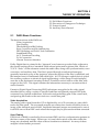
TABLE OF CONTENTS
INTRODUCTION
Specifications ............................................................................................................................................... iii
About This Manual ..................................................................................................................................... iv
SECTION 1 EQUIPMENT REQUIRED/POWER REQUIREMENTS
1.1
1.2
1.3
Equipment Required .................................................................................................................. 1-1
Power Requirements .................................................................................................................. 1-1
Regulatory Notices ..................................................................................................................... 1-2
SECTION 2 INITIAL SETUP AND INSTALLATION
2.1
2.2
2.3
2.4
2.5
Mounting the Digital Soundhead ............................................................................................. 2-1
Electrical Connections to the Digital Soundhead ................................................................... 2-4
Making a Custom Video Cable ................................................................................................. 2-5
Connection to Motor Start Relays–For 2 Projector Installations .......................................... 2-9
Connection to Dolby Cinema Processors .............................................................................. 2-10
2.5.1
Installation of DA20 with CP55 ................................................................................ 2-10
2.5.2
Installation of DA20 with CP65 ................................................................................ 2-40
2.5.3
Installation of DA20 with CP200 .............................................................................. 2-43
2.5.4
Installation of DA20 with CP45 ................................................................................ 2-82
2.5.5
Installation of DA20 with CP500 .............................................................................. 2-85
SECTION 3 CAT. NO. 700 DIGITAL SOUNDHEAD ALIGNMENT
3.1
3.2
3.3
3.4
3.5
3.6
Cat. No.700 Digital Soundhead Alignment ........................................................................... 3-1
Test Setup with Oscilloscope .................................................................................................... 3-1
Focus Adjustment ....................................................................................................................... 3-2
Exciter Lamp Level Confirmation and Adjustment .............................................................. 3-3
Film Path Alignment .................................................................................................................. 3-3
Optical Alignment ...................................................................................................................... 3-4
SECTION 4 MODEL DA20 ALIGNMENT
4.1
4.2
4.3
Cinema Processor Type Selection ............................................................................................. 4-1
Digital Soundhead Delay Adjustment ..................................................................................... 4-2
Digital Surround Delay Adjustment ........................................................................................ 4-3
SECTION 5 THEORY OF OPERATION
5.1
5.2
5.3
5.4
5.5
DA20 Basic Functions ................................................................................................................. 5-1
Discussion of Changeover Technique ..................................................................................... 5-3
Format Control ............................................................................................................................ 5-3
Auxiliary Data Channel ............................................................................................................. 5-4
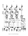
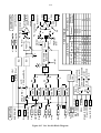
Dolby Digital Decoder Block Diagram .................................................................................... 5-5
SECTION 6 OPERATING INSTRUCTIONS
6.1
6.2
6.3
6.4
6.5
6.6
6.7
How to Identify Sound Tracks on Prints ................................................................................. 6-1
Film Threading ............................................................................................................................ 6-1
Displays ........................................................................................................................................ 6-2
Format Control and Auto Digital Modes ................................................................................ 6-4
Auxiliary Data Channel ............................................................................................................. 6-7
Two Projector Changeover Operation ..................................................................................... 6-7
Operation With An Automation System ................................................................................. 6-8
ii
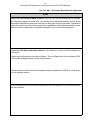
SECTION 7 MAINTENANCE AND ADJUSTMENTS
7.1
7.2
7.3
Digital Soundhead Maintenance .............................................................................................. 7-1
Print Cleanliness ......................................................................................................................... 7-2
Adjustments ................................................................................................................................. 7-2
SECTION 8 UNIT SERVICING / IN CASE OF DIFFICULTY
8.1
8.2
8.3
8.4
Troubleshooting During the Show ........................................................................................... 8-1
Problem Identification ................................................................................................................ 8-2
Determining Software Revision No. ........................................................................................ 8-5
Starting and Program Loading ................................................................................................. 8-6
iii
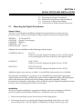
SPECIFICATIONS
DA20 Digital Film Sound
Adaptor
Inputs
Digital Soundhead
Inputs for up to two Dolby Cat.
No.699/700 Digital Soundheads
or comparable inboard readers.
Audio
For use with Dolby CP200
Cinema Processors (separate
input not required for CP65 and
CP55).
Motor Start
Two control inputs detect motor
start signals from projectors 1 and
2.
Projector Changeover
Single input. Ground to select
projector 2, open for projector 1.
Outputs
Audio
Left, Center, Right, Left
Surround, Right Surround, Mono
Surround and Subwoofer (L, C, R,
LS, RS, S and SW).
Auxiliary Data Port
RS-232 standard 8 bit data
available.
Cinema Processor Interface
Format Control inputs and
outputs connect via specific
cables to the Dolby CP65, CP200
or CP55, sensing the currently
selected format and providing
automatic switching as required.
Projector Changeover
Indicates the status of the
changeover control lines.
Power Supply
+15 V, –15 V and +5 V.
Data Status
Numeric LED display indicates
data recovery efficiency from
digital print.
Signal Level
Four-LED display indicates
digital audio signal level for each
channel.
DA20 Internal Controls
System Delay
Three rotary switches set time
delay to achieve synchronization
of sound with picture through
different mounting positions for
digital soundhead. Adjustable
from 4 to 132 frames (16 to 528
perforations) in 1/4-frame
increments.
Surround Delay
Single rotary switch sets delay for
left and right surround channels.
0-140 ms adjustable in 10 ms
increments.
Cinema Processor Type
Selects format protocol and
signal switching for Dolby CP65,
CP200, or CP55.
Front Panel Indicators
Signal Present
One LED per channel indicates
that a signal level above –40 dB is
present at the analog output of
the DA20.
SR•D Digital
Indicates that valid digital data is
being processed.
SR•D Analog
Indicates that the system has
selected Dolby Stereo SR (analog)
operation.
Motor 1/ Motor 2
Indicates “motor running” signals
used for changeover.
DA20 System
Specifications
Output Level
300 mV for Dolby Level (20 dB
below maximum modulation) to
match Dolby Cinema Processors.
Frequency Response
L, C, R, LS, RS, S: 20 Hz to 20 kHz
±0.5 dB. SW: 20 Hz to 120 Hz
±0.5 dB.
Noise Level
More than 72 dB CCIR/ARM
below Dolby level at DA20
outputs.
Maximum Output
20 dB above Dolby level.
Dynamic Range
92 dB.
Projector Speed Tolerance
23 – 26 frames/second, nominal.
Construction
All plug-in modules are
constructed using printed circuit
cards, 96-way DIN connectors.
Conforms to FCC class A EMI
specification.
Dimensions
3 units high, rack mounting; 129
x 283 mm (5.25 in. x 19 in.).
Maximum projection behind
mounting surface 362 mm
(14.25in.).
Shipping Weight
9 kg (20 lb.).
Power Requirements
85 to 265 VAC, 50 - 60 Hz.
Power Consumption
Maximum 100 Watts; typical 60
Watts.
Ambient Operating
Temperature
Up to 40˚C.
Cat. No. 700 Digital
Soundhead
Size
152.4 mm h. x 101.6 mm d. x
254mm w. (6 in. x 4 in. x 10 in.).
Shipping Weight
10.5 kg (24 lb.).
Power Requirements
Exciter lamp requires
approximately 3.5 A at 10 V,
provided by integral exciter lamp
power supply. 85 to 264 VAC;
50- 60 Hz.
Power Consumption
Maximum 100 Watts; typical 60
Watts.
iv
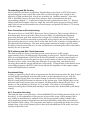
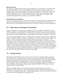
INTRODUCTION
This manual contains essential information on the installation and alignment of the Dolby
Model DA20 Digital Film Sound Processor. It is designed to operate with one of Dolby
Laboratories’ model CP500, CP200, CP65, CP55, or CP45 Cinema Processors to allow
decoding and correct playback of the Dolby Digital optical soundtrack format.
The components of the system are:
Model DA20 SR•D Digital Film Sound Processor
The rack-mounted electronic chassis containing the necessary electronics to drive one or
two Cat. 700 Digital Soundheads, and decode the scanned digital soundtrack into 5.1
channels of high quality audio.
The Cat. No. 700 Digital Soundhead
The soundhead is a film-driven mechanical film transport assembly that provides a stable
film path with a light source, optics, and a CCD (Charge Coupled Device) array. These
components are used to scan digital data from a Dolby Digital print.
The Cat. No. 700 is shipped with a standard 10 meter video cable and a self-contained
Exciter Lamp Power Supply. One Cat. No. 700 is standard with each system; a second
Cat. No. 700 may be purchased for systems requiring changeover.
DA20-to-Cinema Processor Interface Kit
These interface cables connect format control and audio signals from the DA20 to the
Cinema Processor. Some Cinema Processor types require upgrading to take full
advantage of all digital channels produced by the DA20.
About this manual
This manual is intended to be used by individuals who are qualified in the area of cinema
sound installation and service. The basic day-to-day operation of the DA20 is covered in
the DA20 Users’ Manual.
This installation and alignment manual covers the procedures necessary to ensure that
the theatre sound system is accurately aligned to standards that have been established by
Dolby Laboratories. Following these procedures will ensure that the theatre sound
system will accurately reproduce the soundtrack as director and sound mixers intended.
The DA20 Digital Film Sound Processor and Cat. No. 700 Digital Soundhead work
together with Dolby Cinema Processors CP500, CP200, CP65, CP55 or CP45 to provide
the best possible signal to the cinema sound system. The projector, the Dolby processor,
the power amplifiers and the loudspeakers, as well as the auditorium itself, must be
considered when aligning the system for optimum performance. Refer to the appropriate
Cinema Processor manual for alignment instructions for the A and B chains.
v
The system alignment procedure is divided into two parts:
1.
2.
The mechanical alignment of the Cat. No. 700 Digital Soundhead.
The electronic adjustment of the DA20 electronics chassis.
CAUTION
This Installation Manual is for use by qualified personnel only. To avoid electric shock do not perform
any servicing other than that contained in the User’s Manual unless you are qualified to do so.
1-1
SECTION 1
EQUIPMENT REQUIRED/POWER REQUIREMENTS
1.1
1.2
1.3
1.1
Equipment Required
Power Requirements
Regulatory Notices
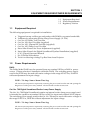
Equipment Required
The following equipment is required for installation:
a.
b.
c.
d.
e.
f.
g.
h.
i.
j.
k.
1.2
Triggered sweep oscilloscope and probes with 20 MHz or greater bandwidth.
Voltmeter for measuring Exciter Lamp Power Supply (11 Vdc)
Cat. No. 69T Dolby Tone Test film
Cat. No. 1010 Sync Test film (supplied)
Cat. No. 1011 Channel ID Test film (supplied)
Cat. No. 1012 Dolby Level Test film
2mm Allen Wrench for Focus Adjustment (supplied)
3mm Allen Wrench for Digital Soundhead Flywheel Installation (supplied)
9/16" (15mm) Open end Wrench
No. 2 Phillips Screwdriver
Tools for removing existing Top Reel Arm from Projector
Power Requirements
DA20
The Dolby Model DA20 may be operated from any nominal 120Vac or 240Vac power
source. Voltage selection is automatic within the DA20. The switching power supply
used in the DA20 may be used with mains voltages in the range 85-265 Vac, 50-60 Hz
without adjustment for input voltage.
FUSE—T 2 Amp 5mm x 20mm Time Lag
The fuse may be inspected or replaced by removing the power cord from the unit and opening the
hinged cover of the power entry module. The fuse holder can then be removed.
Cat. No. 700 Digital Soundhead Exciter Lamp Power Supply
The Cat. No. 700 Digital Soundhead contains an internal exciter lamp power supply and
is intended for operation at nominal 120Vac or 240 Vac input and nominal 10Vdc output.
The switching power supply used in the Cat. No. 700 may be used with mains voltages in
the range 85-265 Vac, 50-60 Hz without adjustment for input voltage.
FUSE—T 2 Amp 5mm x 20mm Time Lag
The fuse may be inspected or replaced by removing the power cord from the unit and opening the
hinged cover of the power entry module. The fuse holder can then be removed.
1-2
1.3
Regulatory Notices
FCC
This equipment has been tested and found to comply with the limits for a Class A digital
device, pursuant to part 15 of the FCC Rules. These limits are designed to provide
reasonable protection against harmful interference when the equipment is operated in a
commercial environment. This equipment generates, uses, and can radiate radio
frequency energy and, if not installed and used in accordance with this instruction
manual, may cause harmful interference to radio communications. Operation of this
equipment in a residential area is likely to cause harmful interference in which case the
user will be required to correct the interference at his or her own expense.
UL
Troubleshooting must be performed by trained technicians. Do not attempt to service the
unit unless you are qualified to do so.
WARNING: Check that the units have been set to the correct supply voltage and that the
correct fuses have been installed. To reduce the risk of fire, replace the fuses only with
the same type and rating. Do not use a ground-lifting adaptor and never cut the ground
pin on the three-prong power plug.
UK
Connections for United Kingdom.
WARNING: THIS APPARATUS MUST BE EARTHED.
As the colours of the cores in the mains lead may not correspond with the coloured
markings identifying the terminals in your plug, proceed as follows:
•
The core which is coloured green and yellow must be connected to the terminal in the plug which is
marked with the letter E or by the earth symbol
, or coloured green or green and yellow.
•
The core which is coloured blue must be connected to the terminal which is marked with the letter
N or coloured black.
•
The core which is coloured brown must be connected to the terminal which is marked with the
letter L or coloured red.
Europe
This unit complies with the requirements of EN 60065, EN 55103-1 and EN 55103-2 when
installed in an E2 environment in accordance with this manual.
1-3
IEC NOTICES
IMPORTANT SAFETY NOTICE
This unit complies with the safety standard IEC65. To ensure safe operation and to guard
against potential shock hazard or risk of fire, the following must be observed:
• If the unit has a voltage selector, ensure that it is set to the correct mains voltage for your supply. If there
is no voltage selector, ensure that your supply is in the correct range for the input requirement of the unit.
• Ensure fuses fitted are the correct rating and type as marked on the unit.
• The unit must be earthed by connecting to a correctly wired and earthed power outlet.
• The power cord supplied with this unit must be wired as follows:
Live—Brown
Neutral—Blue
Earth—Green/Yellow
GB
IMPORTANT – NOTE DE SECURITE
Ce materiel est conforme à la norme IEC65. Pour vous assurer d'un fonctionnement sans danger et de prévenir
tout choc électrique ou tout risque d'incendie, veillez à observer les recommandations suivantes.
• Le selecteur de tension doit être placé sur la valeur correspondante à votre alimentation réseau.
• Les fusibles doivent correspondre à la valeur indiquée sur le materiel.
• Le materiel doit être correctement relié à la terre.
• Le cordon secteur livré avec le materiel doit être cablé de la manière suivante:
Phase—Brun
Neutre—Bleu
Terre—Vert/Jaune
F
WICHTIGER SICHERHEITSHINWEIS
Dieses Gerät entspricht der Sicherheitsnorm IEC65. Für das sichere Funktionieren des Gerätes und zur Unfallverhütung
(elektrischer Schlag, Feuer) sind die folgenden Regeln unbedingt einzuhalten:
• Der Spannungswähler muß auf Ihre Netzspannung eingestellt sein.
• Die Sicherungen müssen in Type und Stromwert mit den Angaben auf dem Gerät übereinstimmen.
• Die Erdung des Gerätes muß über eine geerdete Steckdose gewährleistet sein.
• Das mitgelieferte Netzkabel muß wie folgt verdrahtet werden:
Phase—braun
Nulleiter—blau
Erde—grün/gelb
D
NORME DI SICUREZZA – IMPORTANTE
Questa apparecchiatura è stata costruita in accordo alle norme di sicurezza IEC 65. Per una perfetta sicurezza ed
al fine di evitare eventuali rischi di scossa êlettrica o d'incendio vanno osservate le seguenti misure di sicurezza:
• Assicurarsi che il selettore di cambio tensione sia posizionato sul valore corretto.
• Assicurarsi che la portata ed il tipo di fusibili siano quelli prescritti dalla casa costruttrice.
• L'apparecchiatura deve avere un collegamento di messa a terra ben eseguito; anche la connessione rete deve
avere un collegamento a terra.
• Il cavo di alimentazione a corredo dell'apparecchiatura deve essere collegato come segue:
Filo tensione—Marrone
Neutro—Blu
Massa—Verde/Giallo
I
AVISO IMPORTANTE DE SEGURIDAD
Esta unidad cumple con la norma de seguridad IEC65. Para asegurarse un funcionamiento
seguro y prevenir cualquier posible peligro de descarga o riesgo de incendio, se han de observar
las siguientes precauciones:
• Asegúrese que el selector de tensión esté ajustado a la tensión correcta para su alimentación.
• Asegúrese que los fusibles colocados son del tipo y valor correctos, tal como se marca en la unidad.
• La unidad debe ser puesta a tierra, conectándola a un conector de red correctamente cableado y puesto a tierra.
• El cable de red suministrado con esta unidad, debe ser cableado como sigue:
Vivo—Marrón
Neutro—Azul
Tierra—Verde/Amarillo
D
VIKTIGA SÄKERHETSÅTGÄRDER!
Denna enhet uppfyller säkerhetsstandard IEC65. För att garantera säkerheten och gardera mot
eventuell elchock eller brandrisk, måste följande observeras:
• Kontrollera att spänningsväljaren är inställd på korrekt nätspänning.
• Konrollera att säkringarna är av rätt typ och för rätt strömstyrka så som anvisningarna på enheten föreskriver.
• Enheten måste vara jordad genom anslutning till ett korrekt kopplat och jordat el-uttag.
• El-sladden som medföljer denna enhet måste kopplas enligt foljande:
Fas—Brun
Neutral—Blå
Jord—Grön/Gul
S
BELANGRIJK VEILIGHEIDS-VOORSCHRIFT:
Deze unit voldoet aan de IEC65 veiligheids-standaards. Voor een veilig gebruik en om het gevaar van electrische
schokken en het risico van brand te vermijden, dienen de volgende regels in acht te worden genomen:
• Controleer of de spanningscaroussel op het juiste Voltage staat.
• Gebruik alleen zekeringen van de aangegeven typen en waarden.
• Aansluiting van de unit alleen aan een geaarde wandcontactdoos.
• De netkabel die met de unit wordt geleverd, moet als volgt worden aangesloten:
Fase—Bruin
Nul—Blauw
Aarde—Groen/Geel
NL
2-1
SECTION 2
INITIAL SETUP AND INSTALLATION
2.1
2.2
2.3
2.4
2.1
Mounting the Digital Soundhead
Electrical Connections to the Soundhead
Connection to Motor Start Relays
Connections to Dolby Cinema Processors
Mounting the Digital Soundhead
Adapter Plates
The Cat. No.700 Digital Soundhead casting has bolt patterns for several common
projector types, and may be mounted to these projectors without an adapter plate:
SIMPLEX
35/70 and XL35
CENTURY JJ with 2" bolt adapter
CENTURY 35MM-A
CHRISTIE P35
BALLANTYNE PR0 35
Adapter kits are available for the following projector types.
CINEMECCANICA
V8 / V5
Order Cat. No.690 Adapter Kit (plate Part No. 67185) needed
for re-installing the reel arm to the top of the digital reader.
NORELCO
AAII / DP70
Order Cat. No.695 Adapter Kit (plate Part No. 67079)
KINOTON
DP75, FP20, FP30
Order Cat. No.696 Adapter Kit (plate Part No. 67139)
Additional plates may become available. Consult Dolby Laboratories for availability.
Mounting the soundhead on a projector is accomplished by selecting the appropriate
adapter plates (if needed), attaching the plates to the soundhead casting, then bolting the
plate to the projector and the reel arm or platter guide roller assembly. Lateral
positioning is verified by threading a piece of film through the Digital Soundhead and the
projector, and verifying equal tension on each edge.
Installation
While the Digital Soundhead is rugged and reliable, it has been designed and built to
precision optical and mechanical tolerances. Handle the unit very carefully.
1. Remove the package of parts from the top of the shipping box.
2. Pull out the inner box containing the Digital Soundhead, and slide it out of the
surrounding foam. Place the digital soundhead on a table or bench top, with
2-2
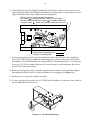
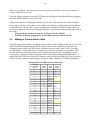
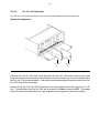
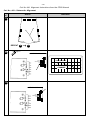
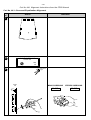
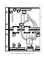
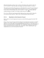
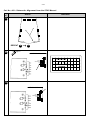
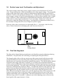
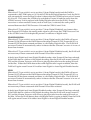
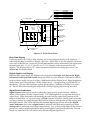
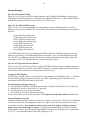
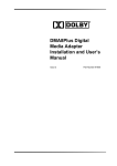
mounting base down. The mounting base is the surface with thirteen mounting holes.
Figure 2.1 shows how the mounting holes correspond to bolt patterns for various
projectors. This diagram shows the hole pattern as viewed from the top, inside the
housing.
1
2
1
2
3
3
4
4
5
5
VIEW FROM INSIDE OF READER LOOKING DOWN
1
CENTURY JJ WITH 50.8 MM (2 INCH) BOLT PATTERN REEL ARM ADAPTER
SIMPLEX 35
2
CHRISTIE
CENTURY 35
3
SIMPLEX 35 - 70
4
CINEMECCANICA V4, V5, V8 (35 mm), V9
5
CINEMECCANICA V8 (70 mm)
Figure 2.1 Mounting Hole Bolt Pattern
3. Remove the six screws which hold the back cover/power supply assembly onto the
Digital Soundhead. Carefully remove the exciter lamp from its holder. Put the
assembly in a safe place.
4. Remove the upper reel arm or guide rollers from the projector on which the Digital
Soundhead is to be mounted.
5. If an adapter kit is necessary, mount the adapter plate to the top of the projector. In
the case of the Cat. No.690 adapter kit, the reader attaches to the projector and the
adapter plate attaches to the top of the reader.
6. Mount the Digital Soundhead to the projector body (or adapter plate) matching the
appropriate set of bolt holes for the projector type.
NOTE: When two Cat. No.700 Digital Soundheads are mounted for use in a two-projector installation, care must be taken to
ensure that the film path lengths between the Digital Soundhead and the picture gates in the two projectors are identical. The
soundhead delay setting in the DA20 is adjusted for correct synchronization of sound and picture during installation. Since only
one adjustment is provided, both projectors must have the same film path length from the Digital Soundhead to the picture gate.
7. Reattach the upper reel arm or guide rollers to the Digital Soundhead, using an
adapter plate if necessary.
2-3
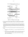
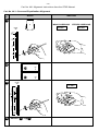
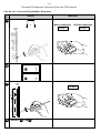
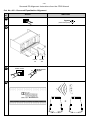
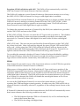
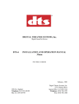
8. Thread film through the Digital Soundhead and first few rollers of the projector and
adjust the placement of the Digital Soundhead such that there is equal tension on each
edge of the film, then firmly tighten the mounting bolts.
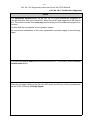
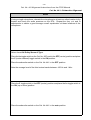
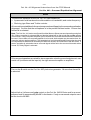
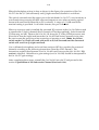
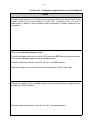
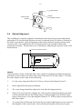
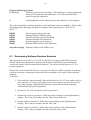
Set film path so that top and bottom tension
arm rollers A are approximately 5 MM (1/4 inch) apart.
Use the white painted semi-circles B for angular alignment
of tension arms C . Make sure that the rollers do not touch.
C
B
A
A
B
C
Digital Print Threading Path
Bypass Threading Path
9. Route appropriate conduit from the audio rack where the DA20 is to be installed to
the Cat. No.700 Digital Soundhead, terminating the conduit at the end of the Digital
Soundhead. The soundhead has an unthreaded 27 mm diameter hole in a 2 mm plate
to accept 3/4" (USA) conduit fittings or 25 mm (Europe) conduit adapters. Be sure to
follow all local electrical codes.
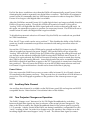
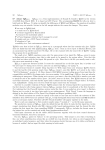
10. Remove the shipping collar using the supplied Allen wrench, and install the Digital
Soundhead flywheel, which is packed separately for shipping (see Figure 2.2).
11. Replace the cover/power supply assembly.
12. Connect mains power to the Cat. No. 700 Digital Soundhead. Route the video cable to
the soundhead (see Section 2.2).
Figure 2.2 Flywheel Mounting
2-4
2.2
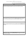
Electrical Connections to the Digital Soundhead
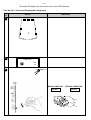
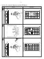
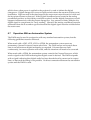
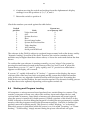
Video Cable Mounting Assembly
The video cable is normally mounted to the Cat. No. 700 by a cable clamp, a locknut and
two washers. Figure 2.3 shows the details of this mounting assembly. This method is
used in non-conduit installations.
12
1
NOTES: (UNLESS OTHERWISE SPECIFIED)
1. FEED CABLE THROUGH WASHERS, PLATE AND CLAMP
2. TIGHTEN CABLE CLAMP ASSEMBLY AROUND EXPOSED BRAIDED
3. TIGHTEN GROUNDING LOCKNUT WITH TEETH FACING REDUCER WASHER.
Figure 2.3 Assembly Video Cable Clamp
If the cable is installed in conduit, then the cable clamp assembly should be removed from
the Cat. No.700 mounting plate and replaced with the appropriate hardware for the
conduit installation.
Exciter Lamp Power
The Cat. No.700 Digital Soundhead comes equipped with a 10V power supply to power
the internal tungsten-halogen exciter lamp. This supply is powered via an IEC mains
connector on the rear of the soundhead. A 2 meter long power cord is included. Outside
the United States the appropriate connector (not supplied) must be attached to the power
cord. See Section 1.3 for the required mains connector wiring. The supply will operate on
85-265 Vac, 50-60 Hz.
Video Cable
The video cable connects the Cat. No.634 CCD Board in the Digital Soundhead to the
DA20. This cable should be pulled through grounded metal conduit or other shielded
wireway to meet EMI emission standards. The male DB25 connector is attached to the
DA20 end of the cable; on the other end a 12-way Molex connector is attached. The
standard cable is 10m (about 30 feet) long. 30m (about 100 feet) or 15m (about 50 feet)
2-5
cables are available. An extra set of connector pins is included in case it is necessary to
cut the cable for any reason.
Plug the Molex connector onto the CCD board in the Digital Soundhead before plugging
the male DB25connector onto the DA20.
Three ferrite blocks are shipped with the Cat. No.700. One of these should be installed
near each end of the video cable. If the cable is installed in conduit then place the blocks
at the DA20 end. If the cable is not in conduit then installation of these ferrite blocks is
essential to prevent excessive RF energy radiation, and should be placed near each end of
the cable.
Plug the Molex connector onto the CCD board in the Digital
Soundhead before plugging the male DB25connector onto the DA20.
2.3
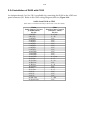
Making a Custom Video Cable
The following information is included for use when a cable is being made up on site. The
cable should be Belden Datalene 8164, which contains four shielded twisted pairs of
computer-grade cable with the shields isolated from each other plus a 100% coverage
overall shield. Using other types of cable may result in unsatisfactory operation. The
overall shield is necessary to prevent RF interference signals from radiating from the
video cable, causing possible complaints and violating government EMI standards. A
metal shell MUST be used on the D-connector and the overall shield MUST be grounded
to the connector shell to ensure proper operation and compliance with EMI regulations.
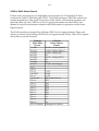
Wiring table for DB25 end of video cable
25 pin
D-connector
pin no.
1
2
3
Molex
pin no.
Wire
Color
Signal
name
n.c.
n.c.
n.c.
4
5
6
7
9
8
Blue
Shield
Black
TTC
TC GND
FTC
7
8
9
10
11
12
White
Shield
Black
TSC
SC GND
FSC
10
11
12
13
n.c.
n.c.
n.c.
n.c.
14
15
16
1
2
6
Black
Shield
Red
Video 0
GND
+15V
17
18
19
3
5
4
Black
Shield
Green
Video 1
GND
–15V
20 through 25
n.c.
2-6
Wiring to the Molex Connector
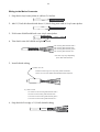
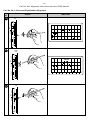
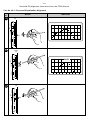
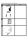
1. Strip back vinyl outer jacket of cable to 3.0 inches.
2. Add 1/2 inch dia heat-shrink about 1/4 inch long near end of vinyl outer jacket.
3. Fold outer shield braid back over vinyl outer jacket.
About 3 inches.
4. Trim back outer foil shield and plastic cords.
foil covering with black & white *
foil covering with black & blue *
foil covering with black & green *
foil covering with black & red *
* foil color may vary depending
upon cable manufacturer
5. Install shrink tubing.
a.) black 1/2" dia
Install 3 inches long over vinyl outer jacket and shield.
Leave .75 inch of the folded back braided shield exposed.
b.) clear 1/8" dia
2.4 inches on foil covering with black & white *
2 inches on foil covering with black & blue *
1.5 inches on foil covering with black & green *
1.2 inches on foil covering with black & red *
6. Strip back foil to edge of 1/8 inch shrink tubing.
2-7
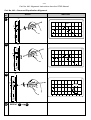
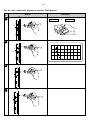
7. Cut exposed wiring and twisted shield to the lengths indicated below; measured from
end of the outer cable casing.
black - cut to 3 inches
shield - cut to 2.9 inches
white - cut to 2.8 inches
end of outer
casing
shield - to 2.6 inches
black - cut to 2.5 inches
blue - cut to 2.4 inches
shield - cut to 2.1 inches
green - cut to 2 inches
black - cut to 1.9 inches
Tin last .12 inch
of shield drain wires
red - cut to 2.2 inches
shield - cut to 1.8 inches
black - cut to 1.6 inches
8. Strip insulated wires back .12 inch and tin
9. Install 1/16 inch dia clear shrink tubing over each drain wire of the twisted pairs and
heat shrink.
.4" long clear shrink tubing
.5" long clear shrink tubing
.5" long clear shrink tubing
.5" long clear shrink tubing
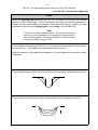
10. Crimp Molex pins onto wires, 12-PL, using Molex tool HTR-2262-20A, then solder
pins to wires.
11.
Arrange wires in the following order and bend them 90 degrees as shown.
k
blac ld
shie
e
whit shield
k
blac
blue red
ld
shie n
gree
k
blac ld
shie
k
blac
2-8
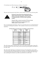
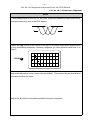
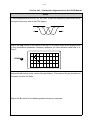
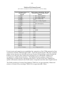
12. Install pins into Molex housing according to wiring table
1
12
The pins must be inserted in the Molex connector block as shown in the following table.
Perform this operation before plugging the male
DB25 connector into the DA20. Incorrect placement
of pins will result in damage to the Cat. No.634
CCD board or the Cat. No. 670 video acquisition
module.
Plug the Molex connector onto the CCD board in the
Digital Soundhead before plugging the male
DB25connector onto the DA20.
Pin 1 is to the left when the Molex connector is connected to the Cat. No.634 CCD Board
in the Cat.No.700 Digital Soundhead. This assembly is easiest if you insert the shortest
leads first.
Wiring table for inserting pins in red Molex connector block
Molex
Wire
Signal
pin no.
color
name
1
Black
Video 0
2
Shield
GND
6
Red
+15V
3
Black
Video 1
4
Green
–15V
5
Shield
GND
7
Blue
TTC
8
Black
FTC
9
Shield
TC GND
10
White
TSC
11
Shield
SC GND
12
Black
FSC
The cable clamp which is attached to the Cat. No.700 cable mounting plate, along with
the exposed braid on the video cable, provide an electrical ground path for the shield of
the video cable.
This video cable shield may be isolated if necessary by loosening the 2 screws which
clamp the video cable shield and installing an insulator around the braided shield (such
as 1/2 inch diameter heat shrink tubing). It is important to re-tighten the cable clamp
after installing the insulation to provide strain relief for the video cable.
2-9
2.4
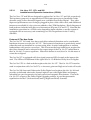
Connection to Motor Start Relays–For 2 Projector Installations
Because the data on the Dolby Digital track is normally read in advance of the picture
gate, in a two projector changeover system the DA20 requires signals in advance of a
changeover. Motor Start contact closures provide these signals (see DA20 to CP wiring
diagrams, Figures 2.9, 2.10, 2.11, 2.18, 2.19).
In a single projector system, the DA20 requires the MS1 signal to be valid when the
projector motor is running in order to allow switching to the analog soundtrack when
digital data is not present. If the MS1 signal is not connected to Digital Ground, the
DA20 will not switch to analog if the digital signal is unreadable. Installation of a relay
is preferred, but installing a wire link from J9 pin 1 to J9 pin 5 will cause the DA20 to
assume that the motor is running constantly, allowing automatic switching to analog if
required. The drawback of a wire link is that the system will be in analog rather than
muted digital during projector startup. The DA20 is shipped with this link installed.
Signal Levels
Normally pulled to +5V through 10k ohms.
Low: less than 1.0 Vdc with respect to signal ground.
High: greater than 3.5 Vdc, less than 18 Vdc with respect to signal ground.
Isolated contact closures from mechanical or opto-isolated relays wired across projector
motors must be used.
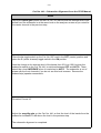
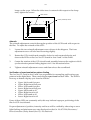
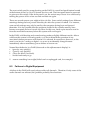
Projector Motor Start Input Connector J9 (DB9 Female) Pinout
DA20 Motor Start Conn. J9
(DB9 Female) Pin no.
1 MS1
2
3
4
5 DGND
6
7
8
9 MS2
External Relays
Close to pin 5 when Proj. 1 running
Common Contact
Close to pin 5 when Proj. 2 running
CLOSED WHEN
PROJ 1 RUNNING
GND
1
5
9
Motor
J9 Start
CLOSED WHEN
PROJ 2 RUNNING
Figure 2.4 Motor Start Connector
2-10
2.5
Connections to Dolby Cinema Processors
The DA20 may be connected to any of five Dolby Cinema Processors: the CP45, CP55,
CP65, CP200, or CP500. Two types of electrical connections must be made between the
DA20 and the cinema processor:
1. Audio through DA20 rear panel connectors J7 and J8.
2. Cinema processor format sensing and control through DA20 rear panel connector J6.
The specifics of connection to these connectors are described for each Cinema Processor
type.
2.5.1 Installation of DA20 with CP55
Refer to the CP55 wiring diagram fold-out (Figure 2.9).
To playback Dolby SR and Dolby Digital films correctly it is highly recommended that
you upgrade the CP55 for Dolby SR. The Dolby Model SRA5 adapter is no longer
available, however you should arrange to acquire a Cat. No. 222SR/A card. This card
replaces the existing Cat. No. 222 noise reduction card and provides two channels of
Dolby SR processing and Dolby A-type noise-reduction.
2.5.1.1
Revised SRA5 installation procedure
(If your theatre is so equipped)
The following section is for an existing installation with Model SRA5 available. If you do
not have an SRA5 installed, skip this section and go to Cat. No.441 Installation, Section
2.5.1.2.
The original SRA5 installation procedure was developed in order to avoid soldering to
the backplane of the CP55. Unfortunately, this method makes use of the AUX format,
which will be needed for use by the DA20. Therefore, if your theater is equipped with an
SRA5 installed in the original way, you will need to revise the installation before
proceeding further. (If you are reconnecting an SRA5 that was previously connected
using the original method, make sure to remove the wire connecting the OBE terminal on
TB2 of the SRA5 to J18 on the CP55. Unplug the D-Sub connector from CP55 J18, cut the
wire at the SRA5 end and discard this wire.)
This procedure describes an alternative method of interfacing the Dolby SRA5 to a CP55
cinema processor. An advantage of this method is that the SRA5 signal output is
returned to the CP55 via the Dolby tone inputs of the Cat.No.222 card instead of using
the non-sync inputs as in the standard method. As a result, the non-sync source can
remain connected to the CP55 non-sync terminals. Using the Dolby tone input also
provides a fixed input level, so no signal calibration needs to be performed.
This method relocates the Dolby Stereo SR format to “03,” making the “AUX” signal
input and selector button available for use in selecting the Dolby Digital format.
The only drawback to this method is that the Dolby tone inputs are only accessible by
soldering directly to the Cat.No.222 edge connector. This is a simple procedure, but one
that must be done carefully to avoid splashes that can cause short circuits.
2-11
Installation
The changes below move format 05 (Dolby Stereo SR) to the format 03 button, freeing up
the aux button for the Dolby Digital input.
1. Set the SRA5 CP selector switch to the “55” position.
2. Set the SRA5 Mode switch located behind the front access panel to “Remote.”
3. Use a shielded pair such as Belden #8451 for the audio and an 18-24 gauge single
conductor wire for the control line. Connect the shields at the SRA5 end only.
Perform the following wiring steps (refer to Figure 2.5):
CP55
SRA5
TB2
See
Figure
2.6
{
TB1
LT
11
7
LT
E
10
8
E
RT
12
9
RT
TB1
J14
15
7
L
9
8
E
1
9
R
TB1
out
out
TB2
8
4
ID7
ID1
CAT. NO. 321
Figure 2.5 SRA5 to CP55 Connections (Alternative Method)
a. Connect the Lt and Rt inputs on the SRA5 to the Optical Preamp Outputs on
TB2 of the CP55.
b. Connect the ID7 terminal on the SRA5 to the ID1 terminal on TB1 of the
Cat.No.321 on the back of the CP55.
c. Connect the Lout and Rout outputs from the SRA5 to the pins of edge
connector J14 on the backplane of the CP55, (see Figure 2.6) by carefully
soldering the wire for the Left channel to pin 15 and Right channel to pin 1.
Solder the ground to pin 9.
2-12
LEFT CHANNEL
GROUND
RIGHT CHANNEL
Figure No. 2.6 Backplane connections at J14
4. Since the function of the front panel 03 button is now changed to format 05 and the
aux button now selects Dolby Digital, an adhesive label is included to re-label the
front panel.
Clean the area of the front door around the format selection buttons with alcohol to
remove any greasy film that may be present and would interfere with good adhesion
of the label to the door. Remove the label backing material and carefully position the
sticker and press it onto the panel. Press it firmly over the entire area to ensure good
adhesion.
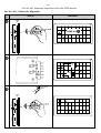
5. Remove the Cat.No.243 from the CP55 and modify the programming of the control
matrix.
a. Locate the line of diodes labeled “F1.” First remove diodes D29 and D33 from
the card.
b. Add two diodes as shown in Figure 2.7. The holes for the anode end of the new
diodes may be filled with solder. Use a solder removing tool to clear these
holes before installing the new diodes. Make sure the polarity is as shown
below on the added diodes.
2-13
c. If an SRA5 is currently installed using the AUX format, remove diodes D61,
D64, D65, D66, and D72 shown in Figure 2.7 with an ✗. Add diode D67 shown
with a ✔.
d. Reinstall the Cat.No.243 in the CP55.
ADD
CONTROL FUNCTIONS
REMOVE D29 & D33
BEFORE ADDING
NEW DIODES
INHIBITS PROJ 1/PROJ 2 PANEL INDICATOR
INHIBITS A-TYPE NOISE REDUCTION
ENABLES RECORD MODE OF CAT. NO. 222
SWITCHES CAT. NO. 222 TO ALTERNATE INPUTS
SPARE
✗
✗
INHIBITS SURROUND OUTPUT OF CAT. NO. 150
ENABLES STEREO DECODING ON CAT. NO. 150
'A' BIT IN INPUT SELECTION CONTROL LOGIC
'B' BIT IN INPUT SELECTION CONTROL LOGIC
ADD INSULATION
TO LEADS
✔
'C' BIT IN INPUT SELECTION CONTROL LOGIC
INHIBITS LEFT CHANNEL OUTPUT
INHIBITS CENTER CHANNEL OUTPUT
INHIBITS RIGHT CHANNEL OUTPUT
INHIBITS SURROUND CHANNEL OUTPUT
ENABLES DECODED SURROUND IN NON-SYNC
✗
INHIBITS OPTICAL BASS EXTENSION
Figure 2.7 Cat. No.243 Diode Modifications
6. Check for proper operation by performing the following tests:
a. Select a non-Dolby format (“01” for example). The “SR OUT” LED on the SRA5
front panel should be on.
b. Select the “05 Dolby Stereo SR” format button. The “SR IN” LED on the SRA5
should be on.
7. Run a pink noise film loop (Cat.No.69) and observe the frequency response in the
auditorium when switching between formats 04 (A-Type) and 05 (SR). Observe that
the pink noise sounds slightly louder and brighter when Dolby SR format 05 is
selected. The LEDs on the SRA5 front panel should indicate “SR IN” for the “05”
format and “SR OUT” for any other format.
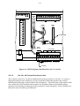
2.5.1.2
Cat. No. 441 installation
The Cat. No.441 card provides the necessary right surround and subwoofer channels
along with Surround EQ. The Cat. No.441 will work in a CP55 even if the CP55 is not
modified, but will only do what a Cat. No.241 will do. To enable its full functioning as
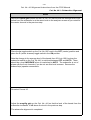
required for Dolby Digital installations, modification of the CP55 backplane is required.
Ensure that you have good access to the backplane (rear) side of the CP55 and have
adequate light. Add leads between pins as described below. See Figure 2.8:
2-14
Cat. No. 242 Pin 19 to Cat. No. 441 Pin 10
Cat. No. 242 Pin 17 to Cat. No. 441 Pin 11
Cat. No. 242 Pin 16 to Cat. No. 441 Pin 12
Cat. No. 242 Pin 9 to Cat. No. 441 Pin 3
Cat. No. 441 Pin T to S
Cat. No. 441 Pin K (gnd) to S
Cat. No. 441 Pin 7 to TB3 Pin 1 (Rs Out)
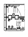
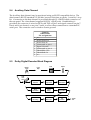
Referring to the fold-out on page 2-17:
DA20 cable light blue wire to Cat. No. 441 Pin M (Rs Input)
DA20 cable white wire to Cat. No. 441 Pin R (digital SW Input)
In addition, ground TB3 pin 2 to the circuit ground at TB3 pin 4. This arrangement
provides muting of the Rs output when in bypass and is necessary to prevent loud
thumps when power to the CP55 is turned on.
The Rs output is now conveniently available at TB3 pin 1. NOTE: the output labeled “S”
on the CP55 is now the Ls output. When any format but Dolby Digital is selected, the
mono surround signal feeds both surround outputs.
The two inputs from the DA20 (Rs and SW) will have to be soldered directly to the
indicated backplane pins of the Cat. No.441. As the cable plugs in to the DA20 end of
things, it will still be possible to disconnect the units from each other without soldering.
The subwoofer output on the CP55 is called B/E (bass extension) and is found at TB3
pin 12. It will now automatically select either the optical input or the Dolby Digital input
according to the format selected by the front panel switches or remote control inputs.
In order to get the correct input level from the Cat. No.85C pink noise generator, two
more modifications are needed. First, cut the trace that leads from the Cat. No.441 socket
pin D toward your right. Solder a wire from the side of the cut trace away from the Cat.
No.441 to Cat. No.441 pin A. Next, connect a 105K resistor (furnished) between Cat.
No.441 connector pins A to D.
Warning: The subwoofer pink noise level in a CP55 so modified but with a Cat. No.241
plugged in will now be 20 dB too low, although the Cat. No.241 will otherwise do just
what it used to do.
ID0
ID1
ID2
2-15
remote
fader
indicator
CAT.NO.
242
28
FF
TB1
from mag
L
mute
C
R
from aux
L
S
C
CAT.NO.
241
16
T
gnd
S9
R
S
from non
sync
L R
CAT.NO.
64B
S8
SO
S1
S2
CUT TRACE HERE
S3
S4
D
S5
R
105K
S6
S7
1
TB2
1
J7
J8
A
J9
bypass
A indicator
1
2
to power amps
L
C
R
S B/E
TB3
Rs OUTPUT
Figure 2.8 CP55 Backplane Modifications for Cat. No.441
2.5.1.3
Cat. No. 441 Control Functions Label
The controls on the Cat. No.441 are different from those of the Cat. No.241. To assist in
alignment and prevent confusion, we have included a label that replaces the control
identification drawing on the inside of the front panel. Clean the area of the inside of the
door where the CP65 modules and controls are described. Remove the label backing
material and carefully position the sticker and press it onto the panel. Press it firmly over
the entire area to ensure good adhesion.
2-16
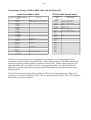
Connections Listing—CP55 to DA20 (See fold-out Figure 2.9)
Audio from DA20 to CP55
DA20
CP Audio out Conn. J8 (DB25 Male)
Pin no.
1 AGND
2 Rs out
3 AGND
4 AGND
5 AGND
6 AGND
7 AGND
8 AGND
9 AGND
10 AGND
11 AGND
12 AGND
13 AGND
14 L out
15 Ls out
16 Re out
17 R out
18 Le out
19 n.c.
20 C out
21 S out
22 n.c.
23 n.c.
24 SW out
25 Spare out
CP55 TB1
GND
CP55 backplane Cat. No. 241 pin M
L from Aux
S from Aux
R from Aux
C from Aux
CP55 Cat. No. 241 Pin R
CP55 to DA20 Sense/Control
DA20 J6 DB25
CP55 Cat. No. 321 TB2
Male
Fanning Strip
Pinout
1 Ctrl0
S0 (01 - mono optical)
2 Ctrl1
S1 (05 - Dolby SR)
3 Ctrl2
S2 (04 - Dolby Stereo)
4 Ctrl3
S3
5 Ctrl4
S4 (22 - mag)
6 Ctrl5
S5
7 Ctrl6
S6 (60 - non-sync.)
8 Ctrl7
S7 (10 - Dolby Digital)
9 n.c
10 n.c
11 n.c
12 GND
GND
13 n.c
14 Sense0
15 n.c.
16 n.c.
17 n.c.
18 n.c.
19 n.c.
20 n.c.
21 n.c.
22 n.c.
23 n.c.
24 n.c.
25 C/O Status (CP55 backplane TB2) Auto C/O
Format sense and control is accomplished via connection of CP S0 through S7 lines,
connected to DA20 CTRL0 through CTRL7. The DA20 monitors CTRL lines and asserts
formats depending on the mode of operation of the DA20. Valid format assertions are
detected when any one CTRL line is low for greater than 80ms. See the DA20 Users’
Manual for specific information related to the DA20 modes of operation and the Auto
Digital feature.
The DA20 switches to format 05 by holding CTRL1 low for approximately 150ms and
returns to format 10 by holding CTRL 7 low for approximately 150ms. (The CP55 requires
about 50ms to switch formats.)
2-19
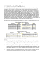
2.4.1.4
Cat. No. 441 Alignment
The Cat. No. 441 alignment procedure (taken from the CP65 Installation Manual) begins here.
Subwoofer Alignment
Cat. No.
85
Cat. No.
150
Remove the Cat. No. 150 Card. Note that when the Cat. No. 150 card is removed, two card
edge connectors are exposed on the backplane and that another slot to the immediate left of
the Cat. No. 150 slot is accessible. This second slot and associated connector are for the Cat.
No. 85C Pink Noise Generator.
Install the Cat. No. 85C Pink Noise Generator in the special slot to the left of the Cat. No. 150
slot. The switches in the Cat. No. 85C are up or down for ON and center for OFF. The phase
is positive when the switches are in the up position and negative in the down position.
2-20
Cat. No. 441 Alignment Instructions from the CP65 Manual
Cat. No. 441—Subwoofer Alignment
Step
No.
1
Indication
Action
CAT. NO. 441
auto
subwoofer
off
2
local active
4
5
6
7
3
8
2
1
9
0
select
local/remote
10
mute
3
10
Dolby Stereo
Digital
2-21
Cat. No. 441 Alignment Instructions from the CP65 Manual
Cat. No. 441—Subwoofer Alignment
Notes
The Subwoofer auto/off switch on the Cat. No. 441 card enables the subwoofer in
formats other than Non-sync (format 60) , Mono (format 01) and magentic no NR (format
22). The switch must be in the auto (up) position at any time the subwoofer system is to
function.
Confirm that the microphone is in the position shown.
All connections established in the room equalization procedure apply to the following
steps.
The main front panel FADER should be active and set to 7. If necessary, press the select
local/remote switch.
Place the Le toggle switch on the Cat. No. 85C card in the ON (up or down) position and
set the CP65 to format 10 Dolby Digital.
2-22
Cat. No. 441 Alignment Instructions from the CP65 Manual
Cat. No. 441—Subwoofer Alignment
Step
No.
Indication
Action
Cat. No.
441
Subwoofer
auto freq
off
Q
opt gain
mag/dig
gain
n-sync
surr
gain
➝
90 dBC
signal
present
tp
on
cut
Dolby
F
40
70
50
60
80
0
F
O
treble
Left Surround
85 dBC
3
4
cut
mid
freq
Q
bass
tp
treble
Right Surround
cut
mid
freq
Q
bass
gain
gnd
signal
present
Cat. No.
441
5
Subwoofer
signal
present
tp
on
cut
n-sync
surr
gain
auto freq
off
Q
opt gain
mag/dig
gain
dB
+10
Dolby
+5
Left Surround
treble
cut
mid
0
freq
Q
bass
tp
–5
Right Surround
treble
cut
mid
freq
Q
–10
bass
gain
gnd
signal
present
.05
Cat. No.
441
Subwoofer
6
signal
present
tp
on
cut
auto freq
off
Q
opt gain
n-sync
surr
mag/dig
gain
gain
Dolby
Left Surround
treble
cut
freq
mid
Q
bass
tp
Right Surround
treble
cut
mid
freq
Q
bass
gain
gnd
signal
present
Cat. No.
441
Subwoofer
7
n-sync
surr
gain
signal
present
tp
on
cut
auto freq
off
Q
opt gain
mag/dig
gain
Left Surround
treble
cut
mid
freq
Q
bass
tp
Right Surround
treble
cut
mid
freq
Q
bass
gain
gnd
signal
present
Dolby
.1
.2
.4
.8
1.6
3.15
6.3
12.5
kHz
2-23
Cat. No. 441 Alignment Instructions from the CP65 Manual
Cat. No. 441—Subwoofer Alignment
Notes
Adjust the mag/dig gain control on the Cat. No. 441 card for a 90 dBC SPL (sound
pressure level) in the theatre. (If this level cannot be obtained it may be necessary to
change the J2 jumper setting to increase or decrease the output.) When you have
obtained this level turn the mag/dig gain control down for an 85 dBC SPL.
Note
This level is only an approximation. Sound pressure level
meters are not appropriate for setting accurate levels of
narrow band signals. The correct final level will be set later
in this procedure using an RTA.
Turn the cut control at the top of the Cat. No. 441 card to the fully clockwise (CW) position
for minimum cut. This disables the subwoofer equalizer circuit.
Note the frequency of the peak in the response. You will need this information in Step
9 following.
Turn the Q control on the Cat. No. 441 card to its mid point (for a moderately wide notch).
Turn the cut control back to the fully counterclockwise (CCW) position for full cut.
2-24
Cat. No. 441 Alignment Instructions from the CP65 Manual
Cat. No. 441—Subwoofer Alignment
Step
No.
Indication
Action
Cat. No.
441
8
Subwoofer
signal
present
tp
on
cut
auto freq
off
Q
opt gain
n-sync
surr
mag/dig
gain
gain
Dolby
Left Surround
treble
cut
freq
mid
Q
bass
tp
treble
Right Surround
cut
freq
mid
Q
bass
gain
gnd
signal
present
Cat. No.
441
Subwoofer
9
signal
present
tp
on
cut
dB
+10
auto freq
off
Q
opt gain
n-sync
mag/dig
surr
gain
gain
DIP
Dolby
+5
Left Surround
treble
cut
mid
0
freq
Q
bass
tp
–5
Right Surround
treble
cut
mid
freq
–10
Q
.05
bass
gain
gnd
signal
present
.1
.2
.4
1.6
.8
3.15
6.3
12.5
kHz
Cat. No.
441
Subwoofer
10
signal
present
tp
on
cut
dB
+10
SKIRTS
Dolby
auto freq
off
Q
opt gain
n-sync
mag/dig
surr
gain
gain
+5
Left Surround
treble
0
cut
mid
freq
Q
bass
–5
tp
cut
mid
freq
–10
Cat. No.
441
Q
Subwoofer
bass
gain
gnd
signal
present
signal
present
tp
on
cut
auto freq
off
Q
opt gain
n-sync
surr
mag/dig
gain
gain
.05
.1
.2
.4
.8
1.6
3.15
6.3
12.5
Left Surround
kHz
dB
Dolby
+10
+5
treble
cut
mid
freq
0
Q
bass
tp
treble
Right Surround
Right Surround
treble
–5
cut
mid
freq
Q
bass
gain
gnd
signal
present
–10
.05
.1
.2
.4
.8
1.6
3.15
6.3
12.5
kHz
2-25
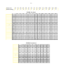
Cat. No. 441 Alignment Instructions from the CP65 Manual
Cat. No. 441—Subwoofer Alignment
Notes
Turn the freq control on the Cat. No. 441 card. A dip in the frequency response will move
along the frequency axis of the RTA display.
Adjust the freq control so the center of the dip is in the same band as the highest peak
in the unequalized subwoofer frequency response you were asked to take note of in
Step 5.
dB
+10
+5
FROM 5 :
0
–5
–10
.05
.1
.2
.4
.8
1.6
3.15
6.3
12.5
kHz
Adjust the cut control so the center of the dip flattens. The center of the dip should be at
the same level as the skirts.
Adjust the Q control for the flattest possible frequency response.
2-26
Cat. No. 441 Alignment Instructions from the CP65 Manual
Cat. No. 441—Subwoofer Alignment
Step
No.
Indication
Action
11
REPEAT 8
1
12
04
→ 10
Dolby Stereo
A-type
CAT. NO. 441
dB
+10
auto
subwoofer
off
NOTE THIS LEVEL
+5
0
CENTER
CHANNEL
–5
–10
.05
13
CAT. NO. 441
auto
subwoofer
off
.1
.2
.4
.8
1.6
3.15
6.3
12.5
kHz
2-27
Cat. No. 441 Alignment Instructions from the CP65 Manual
Cat. No. 441—Subwoofer Alignment
Notes
If using a single microphone, relocate the microphone to at least one other location in the
theatre and check the audio spectrum on the RTA. Repeat the freq, cut, and Q
adjustments to obtain a good average overall equalization at these locations of the
microphone.
Select format 04 Dolby Stereo A-Type.
Place the Le toggle switch on the Cat. No. 85C card in the OFF (center) position and place
the C (center channel) toggle switch in the ON position.
Place the subwoofer switch on the Cat. No. 441 in the OFF position.
Note the average level of the third-octave bands between 100 Hz and 1 kHz.
Place the C toggle switch in the OFF (center) position and place the Le toggle switch in
the ON (up or down) position.
Place the subwoofer switch on the Cat. No. 441 in the auto position.
2-28
Cat. No. 441 Alignment Instructions from the CP65 Manual
Cat. No. 441—Subwoofer Alignment
Step
No.
Indication
Action
Cat. No.
441
Subwoofer
14
dB
signal
present
tp
on
cut
+10
auto freq
off
Q
opt gain
n-sync
mag/dig
surr
gain
gain
+5
Dolby
1
SAME AS 12
0
Left Surround
treble
cut
freq
mid
–5
Q
bass
–10
tp
Right Surround
treble
.05
.1
.2
.4
.8
1.6
3.15
6.3
12.5
kHz
cut
mid
freq
Q
bass
gain
gnd
signal
present
15
dB
+10
auto
subwoofer
off
+5
0
auto
subwoofer
off
–5
–10
.05
10
16
.1
.2
.4
.8
1.6
3.15
6.3
12.5
kHz
Dolby Stereo
Digital
Cat. No.
441
dB
Subwoofer
+10
signal
present
tp
on
cut
auto freq
off
Q
opt gain
n-sync
mag/dig
surr
gain
gain
+10 dB
+5
Dolby
0
Left Surround
treble
–5
cut
mid
freq
Q
–10
bass
tp
Right Surround
treble
cut
mid
freq
Q
bass
gain
gnd
signal
present
.05
.1
.2
.4
.8
1.6
3.15
6.3
12.5
kHz
2-29
Cat. No. 441 Alignment Instructions from the CP65 Manual
Cat. No. 441—Subwoofer Alignment
Notes
Adjust the optical gain control on the Cat. No. 441 card so that the average level of the
bands from the subwoofer is at the same level on the analyzer screen as you noted for
the center channel in the previous step.
Place the Le toggle switch on the Cat. No. 85C card in the OFF (center) position and
place the C (center channel) toggle switch in the ON position.
Note the change in the average level of the bands from 20 Hz to 100 Hz when the
subwoofer switch on the Cat. No. 441 is switched between OFF and AUTO. There
should be a level INCREASE when it is switched to AUTO. The subwoofer is out of
phase with the front channels if you do not see this level increase. Reverse the
subwoofer(s) speaker connections.
Re-select Format 10.
Adjust the mag/dig gain on the Cat. No. 441 so that the level of the bands from the
subwoofer increases 10 dB above the level in the previous step.
The subwoofer alignment is completed.
2-30
Cat. No. 441 Alignment Instructions from the CP65 Manual
Cat. No. 441—Surround Equalization Alignment
Step
No.
Indication
Action
1
2
RIGHT SURROUND
POWER AMP
OFF
3
04
Cat. No.
242
mono eq
mono
gain
L
non-sync
R
Dolby Stereo
A-type
MONO SURROUND
STEREO SURROUND
88 dBC
85 dBC
L
signal C
present R
Ls
F
L
C
test
points R
Ls
L
gain
C
R
Ls
by
Dol
3
40
70
50
80
60
O
0
F
gnd
2-31
Cat. No. 441 Alignment Instructions from the CP65 Manual
Cat. No. 441—Surround Equalization Alignment
Notes
The surround equalizer on the Cat. No. 441 card consists of:
•
A parametric mid-band section with variable cut, bandwidth, and center frequency.
•
Shelving type Bass and Treble controls.
All connections established in the previous procedure still apply to the surround equalization
alignment. Confirm that the microphone is in the position defined earlier. Ensure that
format 04 is selected.
Note: The Cat. No. 441 can be configured for either Mono or Stereo surround operation using link
J3. If Mono operation is selected then an identical signal will be fed to both Ls and Rs outputs
in all formats. If only one power amplifier is to be used for the surround channel then the Ls should
be used. If more than one surround amplifier is to be used, both outputs may be used to feed, for
example, balcony and ground floor. The separate level controls and equalizers may then be used
to compensate for differences caused by the different acoustic environments of the two areas. If
stereo operation is selected a stereo surround signal will be fed to the surround channels when
format 10, Dolby Digital is selected.
If the surround speakers are wired for stereo operation or both surround outputs are in use
switch off (or disconnect the input to) the right surround amplifier or amplifiers.
Turn on the S switch on the Cat. No. 85C pink noise generator. Be sure that format 04
is selected.
Adjust the Ls ( left surround) gain control on the Cat. No. 242 B-Chain card for a sound
pressure level of approximately 85 dBC in the theatre. If only one surround output is used
set the level to 88 dBC.
2-32
Cat. No. 441 Alignment Instructions from the CP65 Manual
Cat. No. 441—Surround Equalization Alignment
Step
No.
Indication
Action
Cat. No.
441
4
Subwoofer
signal
present
tp
on
cut
dB
+10
auto freq
off
Q
opt gain
n-sync
mag/dig
surr
gain
gain
+5
Left Surround
treble
cut
mid
0
freq
Dolby
Q
bass
–5
tp
Right Surround
treble
cut
mid
–10
freq
.05
.1
.2
.4
.8
1.6
3.15
6.3
12.5
kHz
Q
bass
gain
gnd
signal
present
5
Subwoofer
Cat. No.
441
signal
present
tp
on
cut
auto freq
off
Q
opt gain
n-sync
mag/dig
surr
gain
gain
dB
+10
by
Dol
NOTE
+5
Left Surround
treble
cut
0
freq
mid
Q
bass
–5
tp
Right Surround
treble
cut
mid
–10
freq
.05
Q
bass
gain
gnd
signal
present
Cat. No.
441
Subwoofer
6
signal
present
tp
on
cut
auto freq
off
Q
opt gain
n-sync
mag/dig
surr
gain
gain
Left Surround
treble
cut
mid
freq
Q
bass
tp
Right Surround
treble
cut
mid
freq
Q
bass
gain
gnd
signal
present
by
Dol
.1
.2
.4
.8
1.6
3.15
6.3
12.5
kHz
2-33
Cat. No. 441 Alignment Instructions from the CP65 Manual
Cat. No. 441—Surround Equalization Alignment
Notes
Adjust the Left Surround bass control on the Cat. No. 441 card for as flat as possible
low frequency response on the RTA. Use caution when adjusting the bass control; many
surround loudspeaker systems are deficient in their low frequency response. Attempts to
boost the output of such system beyond their capabilities simply wastes amplifier power
and can result in distortion and possibly damage to the surround loudspeakers.
Adjust the Left Surround treble control to its mid point, so that it provides neither cut
nor boost.
Adjust the mid frequency controls as follows: Turn the Cut control fully clockwise (CW).
Set the Q and freq controls to their mid positions.
Note the position of the center of the highest frequency peak in the 350 Hz to 3 kHz region
on the analyzer screen.
Turn the Cut control fully counterclockwise and note the position of the notch produced
by the equalizer.
2-34
Cat. No. 441 Alignment Instructions from the CP65 Manual
Cat. No. 441—Surround Equalization Alignment
Step
No.
Indication
Action
Cat. No.
441
7
dB
Subwoofer
signal
present
tp
on
cut
+10
DIP
auto freq
off
Q
opt gain
n-sync
surr
mag/dig
gain
gain
y
Dolb
+5
Left Surround
treble
0
cut
mid
freq
Q
bass
–5
tp
Right Surround
treble
cut
mid
–10
freq
Q
.05
.4
.2
.1
bass
gain
gnd
signal
present
.8
1.6
3.15
6.3
12.5
kHz
Cat. No.
441
8
Subwoofer
signal
present
tp
on
cut
dB
+10
auto freq
off
Q
opt gain
mag/dig
gain
n-sync
surr
gain
y
Dolb
+5
Left Surround
treble
cut
mid
0
freq
Q
bass
–5
tp
Right Surround
treble
cut
mid
freq
–10
Q
.05
bass
gain
gnd
signal
present
.1
.2
.4
.8
1.6
3.15
6.3
12.5
kHz
Cat. No.
441
Subwoofer
9
signal
present
tp
on
cut
dB
+10
auto freq
off
Q
opt gain
n-sync
mag/dig
surr
gain
gain
Dolby
+5
DESIRED
RESPONSE
Left Surround
treble
cut
mid
0
freq
Q
bass
–5
tp
Right Surround
treble
10
cut
mid
–10
freq
.05
Q
bass
gain
gnd
signal
present
REPEAT 7
→9
.1
.2
.4
.8
1.6
3.15
6.3
12.5
kHz
2-35
Cat. No. 441 Alignment Instructions from the CP65 Manual
Cat. No. 441—Surround Equalization Alignment
Notes
Turn the freq control so that the notch is located over the peak noted in the previous step.
Adjust the Cut and Q controls for the flattest response in this part of the spectrum.
Adjust the treble control on the Cat. No. 441 card for the best approximation to the desired
response shown.
The treble and mid equalizer controls interact. Repeat the adjustments until no further
adjustment is required and you have attained the optimum frequency response.
2-36
Cat. No. 441 Alignment Instructions from the CP65 Manual
Cat. No. 441—Surround Equalization Alignment
Step
No.
Indication
Action
11
Cat. No.
242
MONO SURROUND
STEREO SURROUND
88 dBC
85 dBC
mono eq
mono
gain
L
non-sync
R
L
signal C
present R
Ls
F
40
70
50
60
80
0
F
O
3
gnd
L
C
test
points R
by
Dol
Ls
L
gain
C
R
Ls
RIGHT SURROUND AMP
1
12
ON
LEFT SURROUND AMP
OFF
13
1
Cat. No.
441
auto freq
off
Q
opt gain
n-sync
mag/dig
surr
gain
gain
F
Left Surround
treble
cut
mid
freq
Q
bass
tp
by
Dol
Right Surround
treble
cut
mid
freq
Q
bass
gain
gnd
signal
present
14
REPEAT 4
→ 11
3
40
70
50
80
0
F
O
60
Subwoofer
85 dBC
signal
present
tp
on
cut
2-37
Cat. No. 441 Alignment Instructions from the CP65 Manual
Cat. No. 441—Surround Equalization Alignment
Notes
Adjust the Ls (Left surround) gain control on the Cat. No. 242 B-Chain card for a sound
pressure level of 85 dBC (or 88 dBC if only one surround output is to be used).
If the surround speakers are wired for stereo operation or both surround outputs are in
use, switch on ( or reconnect the input to) the right surround amplifier or amplifiers.
Switch off (or disconnect the input to) the Left surround amplifier or amplifiers.
With the microphone still located at the center of the theatre, adjust the Right Surround
gain control on the Cat. No. 441 surround and subwoofer card for a sound pressure level
of 85 dBC.
Repeat Steps 4 through 11 using the Right Surround pots on the Cat. No. 441 card.
NOTE: When you reach Step 11 remember that the right surround gain control is located
on the Cat. No. 441 board.
2-38
Cat. No. 441 Alignment Instructions from the CP65 Manual
Cat. No. 441—Surround Equalization Alignment
Step
No.
15
Indication
Action
NORMAL BYPASS
bypass
(switch behind panel)
16
Cat. No.
85
17
NORMAL BYPASS
10
Cat. No.
150
Dolby Stereo
Digital
18
=
2-39
Cat. No. 441 Alignment Instructions from the CP65 Manual
Cat. No. 441—Surround Equalization Alignment
Notes
Open the CP65 and place the NORMAL/BYPASS switch in the BYPASS position.
Remove the Cat. No. 85C card and re-install the Cat. No. 150 card.
Restore the BYPASS/NORMAL switch to the NORMAL position.
Confirm that format 04 Dolby Stereo A-Type is selected.
Thread and play the Cat. No. 151 stereo optical surround level film. Check the sound by
walking around the theatre. The surround and center channels should sound equally loud
at most locations and left and right surround channels should sound equally loud and have
similar frequency response in the center of the theatre. If necessary, readjust the left and
right surround gains until you are satisfied with the surround-to-front center balance. A
large change in the gain setting should be unnecessary.
2-40
2.5.2 Installation of DA20 with CP65
Refer to the CP65 wiring diagram fold-out, Figure 2.10. Two cable assemblies are
furnished in the CP65 kit. The ribbon cable with D-connectors on each end connects from
J6 on the DA20 to J18 on the CP65. The round cable plugs into J8 on the DA20 and the
fanning strip on the other end connects to TB4 as shown.
Audio from DA20 to CP65
DA20
CP65
CP Audio Conn. J8 (DB25 Male)
TB4 "From Digital"
Pin no.
Terminal no.
1 AGND
GND
2 Rs out
Rs
3 AGND
4 AGND
5 AGND
6 AGND
7 AGND
8 AGND
9 AGND
10 AGND
11 AGND
12 AGND
13 AGND
14 L out
L
15 Ls out
Ls
16 Re out
17 R out
R
18 Le out
19 n.c.
20 C out
C
21 S out
22 n.c.
23 n.c.
24 SW out
S/W
25 Spare out
2-41
CP65 to DA20 Sense/Control
Format sense and control is accomplished via connection of CP S0 through S7 lines,
connected to DA20 CTRL0 through CTRL7. The DA20 monitors CTRL lines and asserts
formats depending on the mode of operation of the DA20. Valid format assertions are
detected when any one CTRL line is low for greater than 80ms. See the DA20 Users’
Manual for specific information related to the DA20 modes of operation and the Auto
Digital feature.
The DA20 switches to format 05 by holding CTRL2 low for approximately 150ms and
returns to format 10 by holding CTRL 4 low for approximately 150ms. (The CP65 requires
about 50ms to switch formats.)
DA20 J6
DB25 Male
Pinout
1 Ctrl0
2 Ctrl1
3 Ctrl2
4 Ctrl3
5 Ctrl4
6 Ctrl5
7 Ctrl6
8 Ctrl7
9 n.c
10 n.c
11 n.c
12 GND
13 n.c
14 Sense0
15 n.c.
16 n.c.
17 n.c.
18 n.c.
19 n.c.
20 n.c.
21 n.c.
22 n.c.
23 n.c.
24 n.c.
25 C/O Status
CP55 J18
DA25 Female
Pinout
S0 (01 - mono optical)
S1 (04 - Dolby Stereo)
S2 (05 - Dolby SR)
S3
S4 (10 - Dolby SR˙D)
S5
S6
S7 (20 - aux/mag.)
–15V
GND
+15V
ID0 (status lines)
ID1
ID2
ID2
ID4
ID5
ID6
ID7
n.c
n.c
n.c
Changeover Status
2-43
2.5.3 Installation of DA20 with CP200
Refer to the CP200 wiring diagram fold-out, Figure 2.11. The lengths of cable in the
wiring harnesses furnished assume that the DA20 will be mounted directly above the
CP200 and associated MPU. It will be necessary to remove and set aside the ribbon
jumper cable that goes from CP200 JM11 to JM21. Note that removing this jumper
interrupts the signal path for all channels except the subwoofer. If the DA20 is
subsequently removed for any reason, the D-connectors at the ends of the new cables
that connect to JM11 and JM21 must be connected to each other to re-establish the
audio path.
In addition to the audio signal connections, the control logic must be connected between
the units. These connections are shown in Figure 2.11.
In order for the auto digital feature to operate, the DA20 must be equipped with a Cat.
No.611A card. The DA20 also needs the ability to assert each of the four CP200 format
selections to determine which format selector is assigned format 10 and when detected,
assert format 10 when appropriate. This is accomplished via the Cat. No. 493 Auto
Digital Adapter card which is mounted to connector BS21 on the rear panel of the CP200
Control unit. The Cat. No. 493 contains the circuitry required to allow the DA20 to assert
each of the four format selections and to feed back when format 10 is detected.
Additionally, there are four wires which must be either soldered to or attached to barrier
strips on the CP200 control unit backplane. See the information supplied with the Cat.
No. 493 card for details on attachment of these wires.
In order for the subwoofer to work with the DA20, a replacement for the Cat. No.160 is
required. This card is called the Cat. No.560 and is based on the Cat. No.441 subwoofer
and surround card used in the CP65. In addition to subwoofer processing, is offers two
channels of surround equalization.
To make full use of the available dynamic range of the Dolby Digital format, the CP200
requires an improved output fader card. The Cat. No.517 has been designed to fulfill this
requirement and its installation in any CP200 used to play Dolby Digital films is highly
recommended.
Backplane modifications for Cat. Nos.560 and 517 are shown in Figure 2.14 or 2.15.
The Cat. No. 153 Optical Format card from the CP200 control unit must be modified to
allow the DA20 to detect the assertion of the various film formats and thus assert format
10 when appropriate depending on the operating mode of the DA20. The programming
of the Optical Format card assumes that an SRA5 is installed with the CP200 for proper
reversion to the Dolby SR analog soundtrack.
Remove the Cat. No.153 Optical Format Card from the CP200 Control Unit and install the
diodes as follows:
Format Bus Lines
Diode Locations
1,4,13,17,26,29,31
98,103,112,116,125,128,292,388,484
Use a low wattage soldering iron and ensure that there are no solder bridges when
finished. Inspect the installed diodes for correct polarity. Reinstall the Cat. No.153 in the
CP200 control unit.
2-45
2.5.3.1
Cat. Nos. 517, 137L, and 560
Installation and Operation Instructions (CP200)
The Cat. Nos. 517 and 560 are designed to replace the Cat. Nos. 117 and 160, respectively.
Their primary purpose is to upgrade the CP200 cinema processor to handle the wider
dynamic range, lower distortion signals now available from Dolby Digital. They offer
improved performance even if simply plugged in place of the older cards, and additional
features are available if a few wires are added to the CP200 backplane. Block diagrams of
both cards are included with this set of instructions (Figures 2.16 and 2.17). Note that the
installation procedure in a CP200 varies depending upon whether or not the system is
equipped with an accessory unit containing Cat. No.64 equalizers for the P and Q
channels.
Features Of The New Cards
The Cat. No.517 VCA and Line Amp card offers reduced distortion and a considerable
headroom increase over the Cat. No.117. The increase in headroom is particularly useful
when the cards are installed in a system using Altec A-series loudspeakers or modern
loudspeakers with passive crossovers. This is because the large treble boost required for
the screen channels can be selected in the output stage of the Cat. No.517 rather than in
the Cat. No.64 1/3-octave equalizers. When this feature is used, the Cat. No.64s must of
course be re-aligned.
The Cat. No.517 is equipped with four signal presence LEDs located at the input to the
card. The LEDs will illuminate if the signal level is 15 dB below Dolby level or higher.
The Cat. No.137L is a link card that replaces the Cat. No.137. The Cat. No.137L must be
used in conjunction with Cat. No.517s, or incorrect gains and high noise levels will result.
The Cat. No.560 Surround/Subwoofer Dolby Digital card replaces the Cat. No.160 and
provides a dedicated subwoofer channel input for use with digital films and jumper
selectable low-pass frequencies for both optical and magnetic film formats. Used with
Cat. No.517s as part of the Dolby Digital upgrade package, it provides parametric
equalization for the P (Left surround) and Q (Right surround) channels.
2-46
Cat. No. 517 Jumper Settings
Each of the two Cat. No.517 has five programming jumpers and three switches:
• S1 through S3 select a fixed treble boost (9 dB at 5 kHz, 14 dB at 10 kHz) designed to
approximate the large treble equalization required with many screen speakers. Up is
on, down is off. Note that this boost (called treble compensation to distinguish it from
other kinds of eq.) is available only for screen channels. Neither P (Left surround) nor
Q (Right surround) channels have this boost feature, and this circuit is disabled in the
left slot of the CP200 for the S channel.
• J1 through J4 select high or low output gain ranges for the four channels on the card.
The HIGH/LOW selectors on the CP200 Backplane must be left in the HIGH position
at all times for best performance and the gain range jumpers on the cards used
instead.
The CP200 output section actually has three signal paths for surround channel signals-S,
P (Left surround), and Q (Right surround). In a normal monaural surround installation,
only the S output is used. In installations configured to play 70 mm stereo surround films
(format 43), the P (Left surround) and Q (Right surround) outputs are normally used and
the S output ignored.
In some theaters the S output is used to feed rear wall speakers or balcony speakers so as
to have three separate zones with separate level controls. In a stereo surround system, it
is best to re-allocate these speakers to the P (Left surround) and Q (Right surround)
channels as appropriate. (However, where this is not practical, in the DA20 a mono
surround output created by summing the left and right surround signals is provided and
is routed to the S output channel in the CP200.)
HI
ON
L/Le
L
S2
J2
LO
OFF
HI
ON
TREBLE
COMP.
S1
C/S
C
J1
LO
OFF
HI
ON
R/Re
R
S3
J3
LO
HI
OFF
P/Q
S
J4
LO
CAT. NO. 517
Figure 2.12 Cat. No.517 Jumper Settings
OUTPUT
RANGE
2-47
Cat. No. 560 settings
The Cat. No.560 has six programming jumpers and one switch on it:
•
J1 selects high or low output level range for the CP50 Right surround output.
•
J2 selects high or low output level range for the subwoofer channel.
•
J3 selects the surround logic mode. Set to the CP200 position.
•
J4 selects either a 50 or 100 Hz low-pass filter for the subwoofer when in analog optical formats.
The 50 Hz setting is intended for use with JBL, E-V or other modern screen loudspeakers
having good response and power handling down to that frequency. By using this filter
position, overlap between subwoofer and screen speakers is avoided. The 100 Hz setting is
intended for use with Altec A-series and other older screen speakers lacking in power handling
ability at low frequencies. In these cases, the screen speaker equalization should not have boost
applied below 100 Hz so as to avoid a peak in the system frequency response caused by
overlapping outputs from the subwoofer and screen speaker.
•
J5 selects either a 100 or 180 Hz low pass filter for the subwoofer in magnetic sound formats.
The 180 Hz position is intended for installations with no Le or Re speakers, where the
subwoofer carries all bass track information. The 100 Hz position is intended for installations
using the Le and Re speakers to carry the bass track information in conjunction with a
subwoofer. The Le and Re screen speakers are rolled off below 100 Hz by the Cat. No.142. The
subwoofer provides the mid- and low-bass information.
•
J6 disables the CP200 subwoofer output in CP50 installations.
•
S1 enables or disables the subwoofer. The lower position corresponds to the OFF setting on
Cat. No.160 and the upper setting to the AUTO setting.
The Cat. No.560 provides a single band parametric equalizer and variable turnover bass
and treble controls for P and Q surround channels and a single band parametric equalizer
for the subwoofer. The equalizer control functions and locations of the Cat. No.560 are
similar to those on the Cat. No.441 card used in the CP65.
AUTO
SUB
CP200
SW
MODE
S1
J6
CP50
ENABLE
OFF
J4
MAG SW LPF
180
HZ
J5
50 HZ
100
HZ
100 HZ
HI
OPT SW LPF
SW
GAIN
RANGE
J2
SURR MODE
CP200
CP50
LO
J3
J1
CAT. NO. 560
LO
HI
RS GAIN RANGE
Figure 2.13 Cat. No.560 Jumper Settings
2-48
2.5.3.2
Installation of Cat. Nos. 517, 137L, and 560 in
CP200 With NO Accessory Unit
Install the wiring shown in the wiring pictorial diagram (Figure 2-14).
FROM
Description of backplane wiring (no accessory unit):
TO
FUNCTION
SK30 pin A
SK28 pin A
(Cat. No. 517) (Cat. No. 517)
SK30 pin M SK28 pin M
(Cat. No. 517)
SK28 pin M
SK13 pin B21
(Cat. No. 560)
SK 28 pin S
SK28 pin 7
(Cat. No. 517)
SK 28 pin J
SK 28 pin K
SK 30 pin J
SK 30 pin K
optical surround trim VCA signal
Dolby Digital valid logic signal from
DA20 (low = valid)
Dolby Digital valid logic signal from
DA20 (low = valid)
Grounds pin S to indicate card is in left
slot, disabling C/S channel treble
compensation and enabling surround
trim pot to control P (Left surround)
and Q (Right surround) channels.
SK13 pin A13 output to Q (Right surround) EQ (not
(Cat. No. 560) used with Cat. No. 64 surround EQ)
SK13 pin B7
return from Q (Right surround) EQ
(not used with Cat. No. 64 surround EQ)
SK13 pin A5 output to P (Left surround) EQ (not
used with Cat. No. 64 surround EQ)
SK13 pin B3
return from P (Left surround) EQ (not
used with Cat. No. 64 surround EQ)
FIGURE
REF.
A
B
C
D
E
F
G
H
2-49
JM3
JM3
BS1
(1)
JM3
(12)
JM 4
SK18
CAT.141
23
23
16
SK 15
SP2
T
SK 14
CAT.150
SK 13
CAT.160
23
23
21
13
7
5
3
1
1
A
1
A
1
B
1
A
B
JM 10
JM11
JM 9
JM21
JM 22
JM20
C
F
JM 24
H
PJ24
E
1
A
PJ23
B
1
A
1
PJ22
A
PJ21
BS24
Figure 2.14 CP200 Backplane Wiring (no accessory unit)
(1)
proj 2 control
A
JM23
D
B
1
SK28
CAT.117
16
T
proj 1 control
G
SK29
CAT.137
23
23
proj 1
emergency c/o
proj 2
SK30
CAT.117
16
T
2-50
When the backplane wiring is done as shown in the figure, the operation of the Cat.
No.517s for the S, P (left surround), and Q (right surround) channels is as follows:
The optical surround trim (the upper pot on the left-hand Cat. No.517) now functions as
a surround trim governing all three surround outputs at once when an analog optical
format with surround (formats 04 or 05) is selected. A range of + 10 dB around the
nominal setting is provided. In all other formats, this pot is disabled.
When no accessory unit is installed the surround EQ sections of the Cat. No.560 are used
to equalize the P and Q channels (the S channel will not be equalized). Select format 40
(70 mm mag, no NR). Remove the Cat. No.141 from slot 37 of the CP200 processor unit
(first slot in from the right) and insert the Cat. No.85 Pink Noise Generator in its place.
Be sure to mute the processor when removing or inserting a card. Note: the Center
switch on the Cat. No.85 will send pink noise to P (left surround) and the Surround
switch will send it to Q (right surround).
Use a calibrated microphone and a real time analyzer (RTA) to equalize the surround
channels according to the following instructions (from the CP65 manual). The
instructions explain the alignment of a Cat. No.441 card, however the Cat. No.560 EQ
section is identical. References to gain settings (on Cat. No.242) should be interpreted to
be Cat. No.517 gain settings.
After completing these steps, reinstall the Cat. No.141 into slot 37 and proceed to the
section Equalization of the Subwoofer Channel (Section 2.4.3.4).
2-51
No text on this page.
2-52
Surround EQ Alignment Instructions from the CP65 Manual
Cat. No. 441—Surround Equalization Alignment
Step
No.
Indication
Action
1
2
RIGHT SURROUND
POWER AMP
OFF
Dolby Stereo
A-type
MONO SURROUND
STEREO SURROUND
88 dBC
85 dBC
F
3
40
70
80
0
F
O
50
04
60
3
2-53
Surround EQ Alignment Instructions from the CP65 Manual
Cat. No. 441—Surround Equalization Alignment
Notes
The surround equalizer on the Cat. No. 441 card consists of:
•
A parametric mid-band section with variable cut, bandwidth, and center frequency.
•
Shelving type Bass and Treble controls.
All connections established in the previous procedure still apply to the surround equalization
alignment. Confirm that the microphone is in the position defined earlier. Ensure that
format 04 is selected.
Note: The Cat. No. 441 can be configured for either Mono or Stereo surround operation using link
J3. If Mono operation is selected then an identical signal will be fed to both Ls and Rs outputs
in all formats. If only one power amplifier is to be used for the surround channel then the Ls should
be used. If more than one surround amplifier is to be used, both outputs may be used to feed, for
example, balcony and ground floor. The separate level controls and equalizers may then be used
to compensate for differences caused by the different acoustic environments of the two areas. If
stereo operation is selected a stereo surround signal will be fed to the surround channels when
format 10, Dolby Digital is selected.
If the surround speakers are wired for stereo operation or both surround outputs are in use
switch off (or disconnect the input to) the right surround amplifier or amplifiers.
Turn on the S switch on the Cat. No. 85C pink noise generator. Be sure that format 04
is selected.
Adjust the Ls ( left surround) gain control on the Cat. No. 242 B-Chain card for a sound
pressure level of approximately 85 dBC in the theatre. If only one surround output is used
set the level to 88 dBC.
2-54
Surround EQ Alignment Instructions from the CP65 Manual
Cat. No. 441—Surround Equalization Alignment
Step
No.
Indication
Action
Cat. No.
441
4
Subwoofer
signal
present
tp
on
cut
dB
+10
auto freq
off
Q
opt gain
n-sync
mag/dig
surr
gain
gain
+5
Left Surround
treble
0
cut
mid
freq
Dolby
Q
–5
bass
tp
Right Surround
treble
–10
cut
mid
.05
freq
.1
.2
.4
.8
1.6
3.15
6.3
12.5
kHz
Q
bass
gain
gnd
signal
present
5
Subwoofer
Cat. No.
441
signal
present
tp
on
cut
auto freq
off
Q
opt gain
n-sync
mag/dig
surr
gain
gain
dB
by
+10
Dol
NOTE
+5
Left Surround
treble
cut
0
freq
mid
Q
bass
–5
tp
Right Surround
treble
cut
mid
–10
freq
.05
Q
bass
gain
gnd
signal
present
Cat. No.
441
Subwoofer
6
signal
present
tp
on
cut
auto freq
off
Q
opt gain
n-sync
mag/dig
surr
gain
gain
Left Surround
treble
cut
mid
freq
Q
bass
tp
Right Surround
treble
cut
mid
freq
Q
bass
gain
gnd
signal
present
by
Dol
.1
.2
.4
.8
1.6
3.15
6.3
12.5
kHz
2-55
Surround EQ Alignment Instructions from the CP65 Manual
Cat. No. 441—Surround Equalization Alignment
Notes
Adjust the Left Surround bass control on the Cat. No. 441 card for as flat as possible
low frequency response on the RTA. Use caution when adjusting the bass control; many
surround loudspeaker systems are deficient in their low frequency response. Attempts to
boost the output of such system beyond their capabilities simply wastes amplifier power
and can result in distortion and possibly damage to the surround loudspeakers.
Adjust the Left Surround treble control to its mid point, so that it provides neither cut
nor boost.
Adjust the mid frequency controls as follows: Turn the Cut control fully clockwise (CW).
Set the Q and freq controls to their mid positions.
Note the position of the center of the highest frequency peak in the 350 Hz to 3 kHz region
on the analyzer screen.
Turn the Cut control fully counterclockwise and note the position of the notch produced
by the equalizer.
2-56
Surround EQ Alignment Instructions from the CP65 Manual
Cat. No. 441—Surround Equalization Alignment
Step
No.
Indication
Action
Cat. No.
441
7
Subwoofer
signal
present
tp
on
cut
dB
+10
auto freq
off
Q
opt gain
n-sync
surr
mag/dig
gain
gain
DIP
y
Dolb
+5
Left Surround
treble
cut
mid
0
freq
Q
bass
–5
tp
Right Surround
treble
cut
mid
freq
–10
Q
.05
bass
gain
gnd
signal
present
.1
.2
.4
.8
1.6
3.15
6.3
12.5
kHz
Cat. No.
441
8
Subwoofer
signal
present
tp
on
cut
dB
+10
auto freq
off
Q
opt gain
mag/dig
gain
n-sync
surr
gain
y
Dolb
+5
Left Surround
treble
cut
mid
0
freq
Q
bass
tp
–5
Right Surround
treble
cut
mid
freq
–10
Q
.05
bass
gain
gnd
signal
present
.1
.2
.4
.8
1.6
3.15
6.3
12.5
kHz
Cat. No.
441
Subwoofer
9
signal
present
tp
on
cut
dB
+10
auto freq
off
Q
opt gain
n-sync
mag/dig
surr
gain
gain
Dolby
+5
DESIRED
RESPONSE
Left Surround
treble
cut
mid
0
freq
Q
bass
–5
tp
Right Surround
treble
10
cut
mid
–10
freq
.05
Q
bass
gain
gnd
signal
present
REPEAT 7
→9
.1
.2
.4
.8
1.6
3.15
6.3
12.5
kHz
2-57
Surround EQ Alignment Instructions from the CP65 Manual
Cat. No. 441—Surround Equalization Alignment
Notes
Turn the freq control so that the notch is located over the peak noted in the previous step.
Adjust the Cut and Q controls for the flattest response in this part of the spectrum.
Adjust the treble control on the Cat. No. 441 card for the best approximation to the desired
response shown.
The treble and mid equalizer controls interact. Repeat the adjustments until no further
adjustment is required and you have attained the optimum frequency response.
2-58
Surround EQ Alignment Instructions from the CP65 Manual
Cat. No. 441—Surround Equalization Alignment
Step
No.
Indication
Action
11
MONO SURROUND
STEREO SURROUND
88 dBC
85 dBC
F
3
40
70
50
60
80
0
F
O
RIGHT SURROUND AMP
1
12
ON
LEFT SURROUND AMP
OFF
13
1
Cat. No.
441
auto freq
off
Q
opt gain
n-sync
mag/dig
surr
gain
gain
F
Left Surround
treble
cut
mid
freq
Q
bass
tp
by
Dol
Right Surround
treble
cut
mid
freq
Q
bass
gain
gnd
signal
present
14
REPEAT 4
→ 11
3
40
70
50
80
0
F
O
60
Subwoofer
85 dBC
signal
present
tp
on
cut
2-59
Surround EQ Alignment Instructions from the CP65 Manual
Cat. No. 441—Surround Equalization Alignment
Notes
Adjust the Ls (Left surround) gain control on the Cat. No. 242 B-Chain card for a sound
pressure level of 85 dBC (or 88 dBC if only one surround output is to be used).
If the surround speakers are wired for stereo operation or both surround outputs are in
use, switch on ( or reconnect the input to) the right surround amplifier or amplifiers.
Switch off (or disconnect the input to) the Left surround amplifier or amplifiers.
With the microphone still located at the center of the theatre, adjust the Right Surround
gain control on the Cat. No. 441 surround and subwoofer card for a sound pressure level
of 85 dBC.
Repeat Steps 4 through 11 using the Right Surround pots on the Cat. No. 441 card.
NOTE: When you reach Step 11 remember that the right surround gain control is located
on the Cat. No. 441 board.
2-60
Surround EQ Alignment Instructions from the CP65 Manual
Cat. No. 441—Surround Equalization Alignment
Step
No.
15
Indication
Action
NORMAL BYPASS
bypass
(switch behind panel)
16
Cat. No.
85
17
NORMAL BYPASS
10
Cat. No.
150
Dolby Stereo
Digital
18
=
2-61
Surround EQ Alignment Instructions from the CP65 Manual
Cat. No. 441—Surround Equalization Alignment
Notes
Open the CP65 and place the NORMAL/BYPASS switch in the BYPASS position.
Remove the Cat. No. 85C card and re-install the Cat. No. 150 card.
Restore the BYPASS/NORMAL switch to the NORMAL position.
Confirm that format 04 Dolby Stereo A-Type is selected.
Thread and play the Cat. No. 151 stereo optical surround level film. Check the sound by
walking around the theatre. The surround and center channels should sound equally loud
at most locations and left and right surround channels should sound equally loud and have
similar frequency response in the center of the theatre. If necessary, readjust the left and
right surround gains until you are satisfied with the surround-to-front center balance. A
large change in the gain setting should be unnecessary.
2-62
2.5.3.3
Installation of Cat. Nos. 517, 137L, and 560 in a CP200 WITH an
accessory unit fitted with Cat. No. 64 Equalizers for P (Left Surround)
and Q (Right Surround) Channels
Install the wiring shown in the wiring pictorial diagram (Figure 2.15). Note that the
surround equalization sections of the Cat. No.560 are not used.
Description of backplane wiring (with accessory unit and EQ for P, Q channels)
FROM
SK30 pin A
(Cat. No. 517)
SK30 pin M
SK28 pin M
SK 28 pin S
TO
SK28 pin A
(Cat. No. 517)
SK28 pin M
(Cat. No. 517)
SK13 pin B21
(Cat. No. 560)
SK28 pin 7
(Cat. No. 517)
FUNCTION
optical surround trim VCA signal
Dolby Digital valid logic signal from
DA20 (low = valid)
Dolby Digital valid logic signal from
DA20 (low = valid)
Grounds pin S to indicate card is in
left slot, disabling C/S channel treble
compensation and enabling
surround trim pot to control P (Left
surround) and Q (Right surround)
channels.
FIGURE
REF.
A
B
C
D
2-63
JM3
JM3
BS1
(1)
JM3
(12)
JM4
SK18
CAT.141
23
23
16
SK15
SP2
T
SK14
CAT.150
SK13
CAT.160
23
23
21
1
1
A
1
A
1
B
1
A
B
JM10
C
JM11
JM9
JM21
JM22
JM24
JM20
SK30
CAT.117
16
T
SK29
CAT.137
23
23
SK28
CAT.117
16
T
JM23
D
PJ24
BS24
1
A
PJ23
B
A
1
1
PJ22
A
PJ21
(1)
Figure 2.15 CP200 Wiring with accessory unit and EQ for P, Q Channels
proj 2 control
A
proj 1 control
1
proj 1
emergency c/o
proj 2
B
2-64
When the backplane wiring is done as shown in the figure, the operation of the Cat.
No.517s for the S, P (left surround), and Q (right surround) channels is as follows:
The optical surround trim (the upper pot on the left-hand Cat. No.517) now functions as
a surround trim governing all three surround outputs at once when an analog optical
format with surround (formats 04 or 05) is selected. A range of + 10 dB around the
nominal setting is provided. In all other formats, this pot is disabled.
If Cat. No. 64 EQ cards are being installed in the accessory unit for the first time, the
surrounds must be equalized. Refer to the CP200 Installation Manual, page 47.
2.5.3.4
Equalization of the Subwoofer Channel
Refer to the Cat. No.441 alignment instructions on the following pages (from the CP65
Manual).
Remove the Cat. No.141 from slot 23 (fourth slot in from the left), insert the Cat. No.85 in
its place. If Le and Re speakers are also installed, remove the Cat. No.141 from slot 35
(third slot in from the right). Select format 42 (Dolby Stereo 70 mm). Select Le on the Cat.
No.85 to send pink noise to the subwoofer. Use a calibrated microphone and a RTA to
EQ the subwoofer channel according to the instructions. After completing this step,
reinstall the two Cat. No.141s into slots 23 and 35.
2-65
No text on this page.
2-66
Cat. No. 441—Subwoofer Alignment from the CP65 Manual
Step
No.
1
Indication
Action
CAT. NO. 441
auto
subwoofer
off
2
local active
4
5
6
7
3
8
2
1
9
0
select
local/remote
10
mute
3
10
Dolby Stereo
Digital
2-67
Cat. No. 441—Subwoofer Alignment from the CP65 Manual
Notes
The Subwoofer auto/off switch on the Cat. No. 441 card enables the subwoofer in
formats other than Non-sync (format 60) , Mono (format 01) and magentic no NR (format
22). The switch must be in the auto (up) position at any time the subwoofer system is to
function.
Confirm that the microphone is in the position shown.
All connections established in the room equalization procedure apply to the following
steps.
The main front panel FADER should be active and set to 7. If necessary, press the select
local/remote switch.
Place the Le toggle switch on the Cat. No. 85C card in the ON (up or down) position and
set the CP65 to format 10 Dolby Digital.
2-68
Cat. No. 441—Subwoofer Alignment from the CP65 Manual
Step
No.
Indication
Action
Cat. No.
441
Subwoofer
auto freq
off
Q
opt gain
mag/dig
gain
n-sync
surr
gain
➝
90 dBC
signal
present
tp
on
cut
Dolby
F
40
70
50
60
80
0
F
O
treble
Left Surround
85 dBC
3
4
cut
mid
freq
Q
bass
tp
treble
Right Surround
cut
mid
freq
Q
bass
gain
gnd
signal
present
Cat. No.
441
5
dB
Subwoofer
signal
present
tp
on
cut
n-sync
surr
gain
auto freq
off
Q
opt gain
mag/dig
gain
+10
Dolby
+5
Left Surround
treble
cut
mid
0
freq
Q
bass
tp
–5
Right Surround
treble
cut
mid
freq
Q
–10
bass
gain
gnd
signal
present
.05
Cat. No.
441
Subwoofer
6
signal
present
tp
on
cut
auto freq
off
Q
opt gain
n-sync
surr
mag/dig
gain
gain
Dolby
Left Surround
treble
cut
freq
mid
Q
bass
tp
Right Surround
treble
cut
mid
freq
Q
bass
gain
gnd
signal
present
Cat. No.
441
Subwoofer
7
n-sync
surr
gain
signal
present
tp
on
cut
auto freq
off
Q
opt gain
mag/dig
gain
Left Surround
treble
cut
mid
freq
Q
bass
tp
Right Surround
treble
cut
mid
freq
Q
bass
gain
gnd
signal
present
Dolby
.1
.2
.4
.8
1.6
3.15
6.3
12.5
kHz
2-69
Cat. No. 441—Subwoofer Alignment from the CP65 Manual
Notes
Adjust the mag/dig gain control on the Cat. No. 441 card for a 90 dBC SPL (sound
pressure level) in the theatre. (If this level cannot be obtained it may be necessary to
change the J2 jumper setting to increase or decrease the output.) When you have
obtained this level turn the mag/dig gain control down for an 85 dBC SPL.
Note
This level is only an approximation. Sound pressure level
meters are not appropriate for setting accurate levels of
narrow band signals. The correct final level will be set later
in this procedure using an RTA.
Turn the cut control at the top of the Cat. No. 441 card to the fully clockwise (CW) position
for minimum cut. This disables the subwoofer equalizer circuit.
Note the frequency of the peak in the response. You will need this information in Step
9 following.
Turn the Q control on the Cat. No. 441 card to its mid point (for a moderately wide notch).
Turn the cut control back to the fully counterclockwise (CCW) position for full cut.
2-70
Cat. No. 441—Subwoofer Alignment from the CP65 Manual
Step
No.
Indication
Action
Cat. No.
441
8
Subwoofer
signal
present
tp
on
cut
auto freq
off
Q
opt gain
n-sync
surr
mag/dig
gain
gain
Dolby
Left Surround
treble
cut
freq
mid
Q
bass
tp
treble
Right Surround
cut
mid
freq
Q
bass
gain
gnd
signal
present
Cat. No.
441
Subwoofer
9
signal
present
tp
on
cut
dB
+10
DIP
auto freq
off
Q
opt gain
n-sync
mag/dig
surr
gain
gain
Dolby
+5
Left Surround
treble
0
cut
mid
freq
Q
bass
–5
tp
Right Surround
treble
cut
mid
–10
freq
.05
Q
.1
.2
.4
1.6
.8
3.15
6.3
12.5
kHz
bass
gain
gnd
signal
present
Cat. No.
441
10
Subwoofer
dB
signal
present
tp
on
cut
+10
SKIRTS
Dolby
auto freq
off
Q
opt gain
n-sync
mag/dig
surr
gain
gain
+5
Left Surround
treble
0
cut
mid
freq
Q
–5
bass
tp
cut
mid
–10
freq
Cat. No.
441
Q
Subwoofer
bass
gain
gnd
signal
present
signal
present
tp
on
cut
auto freq
off
Q
opt gain
n-sync
surr
mag/dig
gain
gain
.05
.1
.2
.4
.8
1.6
3.15
6.3
12.5
kHz
dB
+10
Dolby
+5
Left Surround
treble
cut
mid
freq
0
Q
bass
tp
treble
Right Surround
Right Surround
treble
–5
cut
mid
freq
Q
bass
gain
gnd
signal
present
–10
.05
.1
.2
.4
.8
1.6
3.15
6.3
12.5
kHz
2-71
Cat. No. 441—Subwoofer Alignment from the CP65 Manual
Notes
Turn the freq control on the Cat. No. 441 card. A dip in the frequency response will move
along the frequency axis of the RTA display.
Adjust the freq control so the center of the dip is in the same band as the highest peak
in the unequalized subwoofer frequency response you were asked to take note of in
Step 5.
dB
+10
+5
FROM 5 :
0
–5
–10
.05
.1
.2
.4
.8
1.6
3.15
6.3
12.5
kHz
Adjust the cut control so the center of the dip flattens. The center of the dip should be at
the same level as the skirts.
Adjust the Q control for the flattest possible frequency response.
2-72
Cat. No. 441—Subwoofer Alignment from the CP65 Manual
Step
No.
Indication
Action
11
REPEAT 8
1
12
04
→ 10
Dolby Stereo
A-type
CAT. NO. 441
dB
+10
NOTE THIS LEVEL
auto
subwoofer
off
+5
0
CENTER
CHANNEL
–5
–10
.05
13
CAT. NO. 441
auto
subwoofer
off
.1
.2
.4
.8
1.6
3.15
6.3
12.5
kHz
2-73
Cat. No. 441—Subwoofer Alignment from the CP65 Manual
Notes
If using a single microphone, relocate the microphone to at least one other location in the
theatre and check the audio spectrum on the RTA. Repeat the freq, cut, and Q
adjustments to obtain a good average overall equalization at these locations of the
microphone.
Select format 04 Dolby Stereo A-Type.
Place the Le toggle switch on the Cat. No. 85C card in the OFF (center) position and place
the C (center channel) toggle switch in the ON position.
Place the subwoofer switch on the Cat. No. 441 in the OFF position.
Note the average level of the third-octave bands between 100 Hz and 1 kHz.
Place the C toggle switch in the OFF (center) position and place the Le toggle switch in
the ON (up or down) position.
Place the subwoofer switch on the Cat. No. 441 in the auto position.
2-74
Cat. No. 441—Subwoofer Alignment from the CP65 Manual
Step
No.
Indication
Action
Cat. No.
441
Subwoofer
14
dB
signal
present
tp
on
cut
+10
+5
auto freq
off
Q
opt gain
n-sync
mag/dig
surr
gain
gain
Dolby
1
SAME AS 12
0
Left Surround
treble
cut
–5
freq
mid
Q
bass
–10
tp
.05
.4
.2
.1
.8
1.6
3.15
6.3
12.5
kHz
Right Surround
treble
cut
mid
freq
Q
bass
gain
gnd
signal
present
15
dB
+10
auto
subwoofer
off
+5
0
auto
subwoofer
off
–5
–10
.05
10
16
.1
.2
.4
.8
1.6
3.15
6.3
12.5
kHz
Dolby Stereo
Digital
Cat. No.
441
dB
Subwoofer
+10
signal
present
tp
on
cut
auto freq
off
Q
opt gain
n-sync
mag/dig
surr
gain
gain
+10 dB
+5
Dolby
0
Left Surround
treble
–5
cut
mid
freq
Q
–10
bass
tp
Right Surround
treble
cut
mid
freq
Q
bass
gain
gnd
signal
present
.05
.1
.2
.4
.8
1.6
3.15
6.3
12.5
kHz
2-75
Cat. No. 441—Subwoofer Alignment from the CP65 Manual
Notes
Adjust the optical gain control on the Cat. No. 441 card so that the average level of the
bands from the subwoofer is at the same level on the analyzer screen as you noted for
the center channel in the previous step.
Place the Le toggle switch on the Cat. No. 85C card in the OFF (center) position and
place the C (center channel) toggle switch in the ON position.
Note the change in the average level of the bands from 20 Hz to 100 Hz when the
subwoofer switch on the Cat. No. 441 is switched between OFF and AUTO. There
should be a level INCREASE when it is switched to AUTO. The subwoofer is out of
phase with the front channels if you do not see this level increase. Reverse the
subwoofer(s) speaker connections.
Re-select Format 10.
Adjust the mag/dig gain on the Cat. No. 441 so that the level of the bands from the
subwoofer increases 10 dB above the level in the previous step.
The subwoofer alignment is completed.
2-76
2.5.3.5
1.
Output level adjustments of Cat. Nos. 517 and 560 in CP200
Adjustment of P and Q channels.
Select format 40 (70 mm mag no NR). Note: If only the S (mono surround output)
is used proceed to step 2.
Remove the Cat. No.141 from slot 37 of the CP200 processor unit (first slot in from
the right), insert the Cat. No.85 pink noise generator in its place. Be sure to mute
the processor when removing or inserting a card. The Center switch on the Cat.
No.85 will send pink noise to P (left surround) and the Surround switch will send
it to Q (right surround). Using a SPL meter set to dBC slow, adjust the P and Q
controls on the Cat. No.517 to obtain 82 dBC on each channel. Switch on pink
noise to both P and Q together and verify that 85 dBC SPL is reached. After
completing this step, reinstall the Cat. No.141 into slot 37.
2.
Adjustment of Left, Center, Right and Le, Re channels.
Remove the Cat. No.141 from slot 35 (third slot in from the right), insert the Cat.
No.85 in its place. Adjust the left, center, right and if installed, left extra and right
extra channels to 85 dBC. Select format 01 (optical mono). Select Center on the Cat.
No.85 and adjust the mono level control on the right Cat. No.517 to obtain
79dBC.
3.
Adjustment of optical surround and mono surround.
Reselect format 40, select Surround on the Cat. No.85. If the mono surround (S)
output is used set the Mag S level control on the left Cat. No.517 to 85 dBC. Select
format 04 (Dolby Stereo optical) and adjust the Opt S surround level control to
read 88 dBC on the SPL meter. Note: This control trims the level of all three
surround outputs (P, Q and S) previously set and therefore will affect whichever
set of outputs (P and Q or S) is used. After completing this step, reinstall the Cat.
No.141 into slot 35.
Thread up and play a loop of Cat. No.151B surround level test film. While in the
most commonly used seating area of the auditorium, listen and check that the level
of the surrounds is subjectively the same as the front channels. If needed, readjust
the Opt surround level control on the left hand Cat. No.517 to obtain the correct
balance.
4.
Adjustment of optical subwoofer level.
Remove the Cat. No.141 from slot 23 (fourth slot in from the left), insert the Cat.
No.85 in its place. Shut off S1 (subwoofer enable) on the Cat. No.560 to mute the
subwoofer output. Select Left and Right on the Cat. No.85; the pink noise will be
decoded to the center channel speaker. Using a RTA, observe the level of the pink
noise from the center channel, note the amplitude on the display. Turn on S1 on
the Cat. No.560. Remove the Cat. No.141 switch card from slot 35 (third slot in
from the right) to disable the other stage speakers. While observing the RTA,
adjust the Opt subwoofer level control on the Cat. No.560 so that the subwoofer
in-band level is the same as the center channel midrange level previously
observed. After completing this step, reinstall the Cat. No.141 into slot 35.
2-77
5.
Adjustment of magnetic/digital subwoofer level.
a.
Systems with subwoofers but no Le or Re speakers.
Select format 42 (Dolby Stereo 70 mm). Select Center on the Cat. No.85,
using a RTA observe the level of the pink noise from the center channel,
note the amplitude on the display. Note: This is not the same level as
observed in step 4. Shut off Center on the Cat. No.85 and select Le. While
observing the RTA, adjust the Mag/Dig subwoofer level control on the Cat.
No.560 so that the subwoofer inband level is 10 dB higher than the center
channel midrange level previously observed. After completing this step,
proceed to step 6.
b.
Systems with subwoofers and Le Re speakers.
Select format 42 (Dolby Stereo 70 mm). Select Center on the Cat. No.85,
using a RTA observe the level of the pink noise from the center channel,
note the amplitude on the display. Note: This is not the same level as
observed in step 4. Shut off S1 (subwoofer enable) on the Cat. No.560 to
mute the subwoofer output. Shut off Center on the Cat. No.85 and select
Le. While observing the RTA, adjust the Mag level control on the Cat.
No.142 so that the Le inband level is 10 dB higher than the midrange level
of the center channel that was previously observed. Turn on S1 on the Cat.
No.560 card. Remove the Cat. No.141 switch card from slot 35 (third slot in
from the right) to disable the other stage speakers. While observing the
RTA, adjust the Mag/Dig subwoofer level control on the Cat. No.560 so that
the subwoofer inband level is 10 dB higher than the center channel
midrange level that was previously observed. Note: The Le and Re
speakers are only used in mag formats with the Cat. No.560 and the Opt
control on the Cat. No.142 is not used.
6.
Remove the Cat. No.85 and reinstall all Cat. No.141 cards. The B-chain
adjustments of the new cards are completed.
2-78
2.5.3.6
DA20 to CP200 Wiring Tables
Refer to the DA20 to CP200 wiring diagram fold-out, Figure 2.11.
Audio from DA20 to CP200
DA20
CP Audio
Conn. J8
(DB25 Male)
Pin no.
1 AGND
2 Rs out
3 AGND
4 AGND
5 AGND
6 AGND
7 AGND
8 AGND
9 AGND
10 AGND
11 AGND
12 AGND
13 AGND
14 L out
15 Ls out
16 Re out
17 R out
18 Le out
19 n.c.
20 C out
21 S out
22 n.c.
23 n.c.
24 SW out
25 Spare out
CP200
JM21 (IDC 20 pin)
Pin no.
1 GND
2Q
3 blank
4 blank
5 blank
6 blank
7 blank
8 blank
9 blank
10 blank
not connected
not connected, cut short
not connected, cut short
11 L
12 P
13 Re
14 R
15 Le
16 blank
17 C
18 S
19 blank
20 blank
not connected to JM21, but
soldered to pin B1 of SK13
not connected, cut short
Audio from CP200 to DA20
DA20
CP Audio
Conn. J7
DB25 Female
Pin no.
1 AGND
2 Rs in
3 AGND
4 AGND
5 AGND
6 AGND
7 AGND
8 AGND
9 AGND
10 AGND
11 AGND
12 AGND
13 AGND
14 L in
15 Ls in
16 Re in
17 R in
18 Le in
19 n.c.
20 C in
21 n.c
22 n.c.
23 n.c.
24 n.c.
1 GND
2Q
3 blank
4 blank
5 blank
6 blank
7 blank
8 blank
9 blank
10 blank
not connected, cut short
not connected, cut short
not connected, cut short
11 L
12 P
13 Re
14 R
15 Le
16 blank
17 C
18 S
19 blank
20 blank
not connected, cut short
25 Spare in
not connected, cut short
CP200
JM11 (IDC 20 pin)
Pin no.
CP200 to DA20 Sense/Control
The DA20 monitors the CP200 Future 8 and Future 11 control lines to determine which
format is selected on the CP200. A low level on Future 8 indicates that format 10 is
selected. A low level on Future 11 indicates that an optical film format is selected. Future
11 is used to cause the DA20 to assert format 10 automatically when the DA20 is in Auto
Digital Mode and valid digital audio is present. See the DA20 Users’ Manual for specific
information on the Auto Digital feature.
CTRL0 through CTRL7 are used to control and read status from the CP200 via the Cat.
No. 493 Auto Digital Adapter board. The DA20 is connected directly to the Cat. No. 493
adapter board using a 25 pin shielded cable. If no Cat. No. 493 is available, the DA20 and
CP200 can operate in non-auto digital mode by connecting the DA20 directly to the CP200
backplane. The signals required for basic operation of the DA20 and CP200 are listed in
the table below in bold type:
2-79
DA20 J6
DB25 Male
Pin Number
1 CTRL0
2 CTRL1
3 CTRL2
4 CTRL3
5 CTRL4
6 CTRL5
7 CTRL6
8 CTRL7
9 N.C.
10 N.C.
11 N.C.
12 GND
13 N.C.
14 Sense0
15 N.C.
16 N.C.
17 N.C.
18 N.C.
19 N.C.
20 N.C.
21 N.C.
22 N.C.
23 N.C.
24 N.C.
25 C/O
Status
Cat,. No. 493
DB25 Female
Pin Number /
CP200 Backplane
1 SW Control / B21 of SK13 (Soldered)
2 Assert GO Button
3 Format A Assert
4 Format B Assert
5 Format C Assert
6 Format D Assert
7 GO Button Monitor
8 Future 11 / A19 of SK27 (Soldered)
9 N.C.
10 N.C.
11 N.C.
12 GND / BS23 Pin 5
13 N.C.
14 Future 8 / Pin 14 of SK15 (Soldered)
15 N.C.
16 N.C.
17 N.C.
18 N.C.
19 N.C.
20 N.C.
21 N.C.
22 N.C.
23 N.C.
24 N.C.
25 Projector 2 / BS23 Pin 6
(The CTRL0 line held low causes the CP200 to reproduce the digital SW channel from the
DA20.)
9
11
Figure 2.16 Cat. No.517 Block Diagram
K
T
from EQ
Fader
control
+
level
range
level
range
P3/J3
level
range
P2/J2
J
10 k
+
level
range
P1/J1
to EQ
Logic
mono / S
gain trim
+ 6v
- 6v
P4/J4
A
M
13
S
5
S/P/Q
S master
gain in/out
R/ Re
gnd for
SR•D
valid
L/ Le
gnd for
mono/opt
gnd to
inhibit
treble
comp.
C/S 10
INPUTS
Lo
Hi
Lo
Hi
Lo
Hi
Lo
Hi
treble comp
treble comp
out
in
S3
out
in
S2
out
in
S1
treble comp
(disabled in
S slot of CP200)
S/P/Q level
R/Re level
L/Le level
C/S level
4
16
15
3
S/P/Q
R/ Re
L/ Le
C/S
OUTPUTS
2-80
A13
Right
Figure 2.17 Cat. No.560 Block Diagram
A1
Test
TP4
+
+
+
D
A4
B21
Low for SR•D
A20
Mag A (CP200)
Open (CP50)
Mono
S1
P3
SW
Surr
Mode
180 Hz
20 kHz
180 Hz
100 Hz
100 Hz
50 Hz
CP50 (SR•D)
CP200
A12
Fader
CP200 A5
LOGIC
B/E (CP200)
GND (CP50) B13
CP50
B1
A6
Le
mag
SR•D
B18
R opt
A7
B17
spare
Re
mag
A17
L opt
SUBWOOFER
A5
Left
SURROUND
INPUTS
+
Rt out
Lt out
C
B
A
EQ
Surround controls
D, not D
Downward Expander
on/off
Subwoofer controls
A-C
Fader
Law
P5
P4
not D
CP50 (non SR•D)
B10
B12
high
x
x
high
x
x
low
low
low
low
low low
low low
x
x
low
high
high
high
high
B/E Mono
x
x
x
high
high
low
low
P6
Mag
A
x
x
x
high
low
high
low
CP
200
CP 200
A16
CP50
CP50
B11
SWITCHES ON
Downward
Subwoof
Expander
x
none
none
x
none
x
on
A
on
B
off
C
off
C
TRUTH TABLE
A
A
Subwoofer
Right Surround
B5
CP50
CP200
B7
P2 level range
B3
Left Surround
OUTPUTS
P1 Rs level range
Mag/digital
level
Fader
Optical
level
LOGIC INPUTS
NR
opt Le
A10 opt Re
A9
Rs level
Fader
SR•D
on/off
Downward
Expander
EQ
EQ
n/c
n/c
2-81
2-82
2.5.4 Installation of DA20 with CP45
An Adapter board, Cat. No. 545, is available for connecting the DA20 to the CP45 rear
panel connector J10. Refer to the CP45 wiring Diagram fold-out, Figure 2.18.
Audio from DA20 to CP45
(This cable is Available from Dolby Laboratories as Part No. 83306)
DA20
Audio Out to CP Conn.
J8 (DB25 Male)
Pin No.
1 AGND
2 Rs Out
3 AGND
4 AGND
5 AGND
6 AGND
7 AGND
8 AGND
9 AGND
10 AGND
11 AGND
12 AGND
13 AGND
14 L Out
15 Ls Out
16 Re Out
17 R Out
18 Le Out
19 N.C.
20 C Out
21 N.C.
22 N.C.
23 N.C.
24 SW Out
25 Spare Out
CP45
Non-Sync/Aux Conn. J5
(“Phoenix” Male)
Pin No.
4 - Com
6 - Rs
N.C.
N.C.
N.C.
N.C.
N.C.
N.C.
N.C.
N.C.
N.C.
N.C.
8 - Com
1-L
5 - Ls
N.C.
3-R
N.C.
N.C.
2-C
N.C.
N.C.
N.C.
7 - SW
N.C.
2-83
DA20 to CP45 Sense/Control
(This cable is Available from Dolby Laboratories as Part No. 83135)
DA20 CP Sense/Control J6
(DB25 Male)
Pinout
1 CTRL0
2 CTRL1
3 CTRL2
4 CTRL3
5 CTRL4
6 CTRL5
7 CTRL6
8 CTRL7
9 N.C.
10 N.C.
11 N.C.
12 GND
13 N.C.
14 Sense 0
15 N.C.
16 N.C.
17 N.C.
18 N.C.
19 N.C.
20 N.C.
21 N.C.
22 N.C.
23 N.C.
24 N.C.
25 C/O Status
CP45 Adapter Board Cat. No. 545
Control Logic J12 (DB15 Male)
Pinout
7 - (01 - mono optical)
5 - (04 - Dolby Stereo)
6 - (05 - Dolby SR)
N.C.
10 - (10 - Dolby Digital)
N.C.
9 - (60 - Non-Sync)
N.C.
N.C.
N.C.
N.C.
4 - GND
N.C.
N.C.
N.C.
N.C.
N.C.
N.C.
N.C.
N.C.
N.C.
N.C.
N.C.
N.C.
15 - Projector C/O
Format sense and control are accomplished via connection of the CP500 automation lines
connected to DA20 CTRL0 through CTRL7. The DA20 monitors the CTRL lines to detect
when various formats are selected and asserts Format 10 depending on which mode the
DA20 is in. In all cases, the control lines must be low for a minimum of 80ms to be
recognized as valid format assertions. The DA20 will assert various control lines
depending on which mode is selected on the DA20. See the DA20 Users’ Manual for
specific information related to the DA20 modes of operation and the Auto Digital feature.
The DA20 switches to Format 05 by holding CTRL2 low for approximately 150ms and
returns to Format 10 by asserting CTRL4 low for approximately 150ms.
2-85
2.5.5 Installation of DA20 with CP500
Refer to the CP500 wiring Diagram fold-out, Figure 2.19
CP500 to DA20 Connection Tables
Audio from DA20 to CP500
DA20
CP Audio Out Conn. J8
(DB25 Male)
Pin No.
1 AGND
2 Rs Out
3 AGND
4 AGND
5 AGND
6 AGND
7 AGND
8 AGND
9 AGND
10 AGND
11 AGND
12 AGND
13 AGND
14 L Out
15 Ls Out
16 Re Out
17 R Out
18 Le Out
19 N.C.
20 C Out
21 N.C.
22 N.C.
23 N.C.
24 SW Out
25 Spare Out
CP500
6 Channel Input Conn (DB25)
Pin No.
1 Signal Ground
2 Right Surround Channel Input
3 Signal Ground
4 Signal Ground
5 Signal Ground
6 Signal Ground
7 Signal Ground
8 Signal Ground
9 Signal Ground
10 Signal Ground
11 Signal Ground
12 Signal Ground
13 Signal Ground
14 Left Channel Input
15 Left Surround Channel Input
16 N.C.
17 Right Channel Input
18 N.C.
19 N.C.
20 Center Channel Input
21 N.C.
22 N.C.
23 N.C.
24 Sub Woofer Channel Input
25 N.C.
2-86
DA20 to CP500 Sense/Control
DA20
CP Sense/Control J6
(DB25 Male)
Pinout
1 CTRL0
2 CTRL1
3 CTRL2
4 CTRL3
5 CTRL4
6 CTRL5
7 CTRL6
8 CTRL7
9 N.C.
10 N.C.
11 N.C.
12 GND
13 N.C.
14 N.C.
15 N.C.
16 N.C.
17 N.C.
18 N.C.
19 N.C.
20 N.C.
21 N.C.
22 N.C.
23 N.C.
24 N.C.
25 C/O Status
CP500
Automation
(DB25 Female)
Pinout
1 SK1 Format Select Input
2 SK2 Format Select Input
3 SK3 Format Select Input
4 SK4 Format Select Input
5 SK5 Format Select Input
6 SK6 Format Select Input
7 SK7 Format Select Input
8 SK8 Format Select Input
9 N.C.
10 N.C.
11 N.C.
12 GND
13 N.C.
14 N.C.
15 N.C.
16 N.C.
17 N.C.
18 N.C.
19 N.C.
20 N.C.
21 N.C.
22 N.C.
23 N.C.
24 N.C.
25 Projector Status
Format sense and control are accomplished via connection of the CP500 automation lines
connected to DA20 CTRL0 through CTRL7. The DA20 monitors the CTRL lines to detect
when various formats are selected and asserts Format 10 depending on which mode the
DA20 is in. In all cases, the control lines must be low for a minimum of 80ms to be
recognized as valid format assertions. The DA20 will assert various control lines
depending on which mode is selected on the DA20. See the DA20 Users’ Manual for
specific information related to the DA20 modes of operation and the Auto Digital feature.
The DA20 switches to Format 05 by holding CTRL2 low for approximately 150ms and
returns to Format 10 by asserting CTRL4 low for approximately 150ms.
Note that if a custom format screen is constructed on the CP500, Formats 05 and 11 must
not be moved from the factory pre-set locations if connected as described in the CP500 to
DA20 connection diagram. If the wiring harness is modified, these formats can be moved
to different soft keys. Please see the CP500 Installation Manual for specific information on
the operation of the automation connector on the CP500.
3-1
SECTION 3
CAT. NO. 700 DIGITAL SOUNDHEAD ALIGNMENT
3.1
3.2
3.3
3.4
3.5
3.6
3.1
Cat. No.700 Digital Soundhead Alignment
Test Setup with Oscilloscope
Focus Adjustment
Exciter Lamp Level Confirmation and Adjustment
Film path Alignment
Optical Alignment
Cat. No. 700 Digital Soundhead Alignment
Mechanical alignment of the Cat. No.700 Digital Soundhead consists of making sure the
film path through the Digital Soundhead is aligned with the path through the rest of the
projector.
1.
Thread a length of film from supply reel through the Digital Soundhead (refer to
the threading diagram located on the soundhead), and on through the projector as
you would any film.
2.
Apply tension to the film and inspect for equal tension on both edges of the film.
3.
Check for uneven forces on the rollers, or twisting of the film.
4.
When the path is aligned, tighten the soundhead mounting bolts and reel arm.
3.2
Test Setup with Oscilloscope
The following test setup will enable adjustment of focus and confirmation and adjustment
of lamp level and optical alignment.
1.
Make sure power to Cat. No.700 Digital Soundhead is provided. Power to the
DA20 should also be turned on.
2.
Remove the DA20 front panel (see Section 8).
3.
Connect a probe from Channel 1 of a 20MHz or greater bandwidth oscilloscope to
the VIDEO Test Point (TP1) on the Cat. No.670 Video Acquisition Card in slot 12
of the DA20(leftmost card), with the ground lead attached to VGND (TP2, just
below TP1).
4.
Connect a second probe from the scope’s Channel 2 to the CLAMP signal test point
(TP3) to trigger the scope. Connect the second probe’s ground wire to DGND
(TP7).
5.
Set the trigger source on the scope to Ch. 2.
3-2
6.
Adjust the Ch 2 vertical trace position to move the trace off the screen. It is not
necessary to view this signal once triggering has been established.
Cat. No.670 Video Board (DA20 slot 12) Test Points:
VIDEO
VGND
CLAMP
TRACK
+15
+5
DGND
–15
TP1 (white)
TP2 (black)
TP3 (green)
TP4 (brown)
TP5 (yellow)
TP6 (red)
TP7 (black)
TP8 (blue)
The CCD video signal
Ground reference for Video signal
Horizontal Sync. to view Video scan.
Perforation rate - check for 96Hz
+15V power supply rail
+5V power supply rail
Digital ground reference
–15V power supply rail
Adjust the scope for 1 horizontal trace across the screen, and adequate vertical gain
(approx. 2 sec/div. horizontal, 1 V/div. vertical). With a Dolby Digital film threaded and
running in the projector, observe the video waveform. (see figure in Section 3.3).
3.3
Focus Adjustment
Cat. No.700 Digital Soundheads are factory adjusted and should not require adjustment
during installation. If the soundhead has become misadjusted, focusing may be
performed. Using the setup as above, adjust the objective lens/CCD assembly in the
reader head by loosening the 2mm hex socket set screw (located below the lens bore)
which holds the lens/CCD assembly in place, and moving the assembly back and forth.
There are two methods for moving the assembly. A flat blade screw driver inserted in the
oval slot above the lens can be twisted to slide the assembly. Alternately, if the CCD
circuit board cover is removed, the assembly can be moved back and forth with the
thumb and forefinger. The best focus is achieved when the scope pattern has minimum
brightness in the center of the trace. There will always be some light here; one is looking
for the most “focused looking” display, with minimum brightness inside the envelope.
This should correlate with minimum error rate. Re-tighten the lens holding screw.
2.7 to 5 volts
Adjust for minimum brightness in center of image.
3-3
3.4
Exciter Lamp Level Confirmation and Adjustment
The output voltage of the lamp power supply is factory-set to be between 9.5 and 10
volts. Lamp intensity has a direct relationship to the video signal voltage. The acceptable
range for the peak video signal voltage (of unobstructed light through the perf hole) is
between 2.7 and 5 volts (see figure in Section 3.3). Under normal circumstances, the lamp
power supply voltage will never need adjustment to achieve the acceptable video voltage
range. However, some combinations of individual lamp intensity and projector speed
may result in a video signal outside the 2.7 to 5 volt range. In that case, it may be
necessary to adjust the lamp power supply. See diagram for adjustment location (VR1).
Do not adjust voltage above 10 volts at output of power supply.
If the top of the video waveform is not reasonably flat (+/–1 division), check for dirt,
dust, or other obstruction to the light path, and clean (see Section 7).
[VR1]
Voltage Adjust
3.5
Film Path Alignment
The film path is aligned during manufacture and should not require adjustment during
installation. The procedure for confirming or adjusting the film path follows.
The flanged guide roller on the top tension arm (the spring loaded roller between the
sprocket and drum) is the only film guide with provision for lateral adjustment. The
specification for its position is based on nominal film position. The film should be guided
so that the inner edge of the film is 25.4mm (+0.1-0.1mm) from a machined reference
surface on the soundhead housing (19mm diameter unpainted spot between the sprocket
boss and the light pipe). The outer edge of the flange on the guide roller therefore should
measure 61.9mm from the reference surface. To adjust the position of the guide, the rear
panel of the soundhead, the flywheel, and the tension arm spring must be removed. See
the diagram below for the location of the two screws that control the position of the
roller. Before loosening the clamp screw, note the angular position of the spring arm with
respect to the tension arm on the front of the soundhead (return the arm to the same
angular relationship prior to tightening). The lateral adjustment screw can be turned
after the clamp screw is loosened. A quarter turn of the adjusting screw will move the
lateral guide roller approximately 0.1mm.
3-4
CLAMP SCREW
LATERAL
ADJUSTMENT SCREW
TENSION ARM
SPRING
3.6
Optical Alignment
The soundhead is optically aligned at manufacture and should not require adjustment
unless the CCD circuit board has been moved or replaced (the CCD sensor is located on
the CCD circuit board. Optical alignment of the sensor depends on the position of the
circuit board). Two adjustments of CCD board position are possible: lateral and
rotational (azimuth). The procedure for confirming or adjusting the position of the CCD
board follows.
AZIMUTH ADJUSTMENT SCREWS
CCD CIRCUIT
BOARD
LATERAL ADJUSTMENT SCREWS
Lateral
Lateral position can be confirmed if the video signal (of unobstructed light through the
perf hole) on the oscilloscope falls in the center of the total CCD video signal. To center
the video signal on the scope do the following:
1.
Use the scope setup described in 3.2 above, observe both channel 1 and 2.
2.
Run a digital film through soundhead.
3.
The scope image should be adjusted to look like the diagram below.
4.
If the CCD circuit board is aligned, the video signal of light through the perf hole
will be centered between the falling edge of clamp (trigger) trace and the rising
edge of clamp trace. As in the diagram, distance “X” will be equal on each side of
the video signal.
5.
To re-align the CCD board, first loosen the two lateral adjustment screws shown in
the diagram of the circuit board. Move the board laterally while observing the
3-5
image on the scope. When the video trace is centered with respect to the clamp
trace, tighten the screws.
VIDEO TRACE
CLAMP (TRIGGER) TRACE
X
X
Azimuth
The azimuth adjustment controls the angular position of the CCD board with respect to
the film. To adjust the azimuth of the CCD:
1.
Loosen the two azimuth adjustment screws shown in the diagram. The focus
adjustment screw will also need loosening slightly
2.
Rotate the CCD circuit board assembly clockwise and counterclockwise and
observe the LEDs on the Cat. No.671 boards in slots 2 and 3 of the DA20.
3.
Center the rotation of the CCD circuit board assembly between the angles at which
synchronization pattern finding begins to fail. See discussion below.
4.
Tighten azimuth adjustment screws and then refocus the soundhead.
Verification of synchronization pattern finding
The Cat. No.671 cards in slots 2 and 3 are responsible for resampling and locating sync
patterns in the digital data. These cards display sync found on their LEDs. The 8 LEDs
from top to bottom display sync found as follows:
•
•
•
•
•
•
•
•
Upper Left found first pass
Upper Right found first pass
Lower Left found first pass
Lower Right found first pass
Upper Left found at all
Upper Right found at all
Lower Left found at all
Lower Right found at all
If any of these LEDs are constantly unlit, this may indicate improper positioning of the
film or CCD circuit board.
Proper adjustment of position, intensity and focus will be verified by observing no error
light flashing and minimum error rate displayed on the Cat. No.673 Fifo/Resources/
Error Correction/Delay board (slot 15). See Section 8.
4-1
SECTION 4
MODEL DA20 ALIGNMENT
4.1 Cinema Processor Type Selection
4.2 Digital Soundhead Delay Adjustment
4.3 Digital Surround Delay Adjustment
4.1
Cinema Processor Type Selection
The top rotary switch on the Cat611A Cinema Processor Interface Card is used to select
the appropriate Cinema Processor type and operating mode. Setting this switch correctly
is necessary in order for the DA20 to properly sense format assertions and to enable or
disable Auto Digital mode. The following table describes the CP Type switch selections:
CP Type
Switch
Setting
0
1
2
3
4
5
6
7
8
9
A
B
C
D
E
F
Cinema Processor and Mode
Do Not Use (LEDs
CP55
CP45/65/500
CP200
Do Not Use (LEDs
CP55
CP45/65/500
CP200
Do Not Use (LEDs
CP55
CP45/65/500
CP200
Do Not Use (LEDs
Do Not Use (LEDs
Do Not Use (LEDs
Do Not Use (LEDs
will Flash)
Auto Digital
Auto Digital
Auto Digital
will Flash)
Auto Digital Disabled
Auto Digital Disabled
Auto Digital Disabled
will Flash)
Digital Always
Digital Always
Digital Always
will Flash)
will Flash)
will Flash)
will Flash)
When the CP Type switch is set to one of the Auto Digital Enabled positions, the DA20
will automatically assert a Format 10 command to the cinema processor if the DA20
detects that the cinema processor is in a film format and there is valid Dolby Digital audio
available. The DA20 will not automatically assert Format 10 unless a film format has been
asserted first (01,04,or 05). See the DA20 Users manual for specific information on the
operation of the Auto Digital feature.
If the user does not wish the DA20 to automatically assert Format 10, the Auto Digital
disabled modes should be used. This will disable any format assertions by the DA20
except reversion assertions when playing in Format 10.
The Digital Always modes are to be used for testing and theatre alignment only. These
selections disable the reversion system and force the DA20 to remain in Format 10 always.
These modes are typically used for theatre test and alignment when running film loops to
keep the DA20 from reverting at splices.
4-2
4.2
Digital Soundhead Delay Adjustment
On a Dolby Digital print, the digital data is located 6 frames in advance of the analog
soundtrack, and 26 frames in advance of the picture. When the Digital Soundhead is
mounted above the analog soundhead (as with the Cat. No. 700) a delay is necessary to
synchronize the digital soundtrack with the analog track and the picture. In the DA20,
this delay is set by adjusting three middle rotary switches on the Cat. No. 611A Cinema
Processor Interface Card (located between the analog LED and the proj. 1 LED of the C.P.
Status slot in the front panel of the DA20). SW1 (upper), SW2 (center), and SW3 (lower)
select a delay from 016 to 528 film perforations. SW1 selects hundreds of perfs, and has
the largest effect on delay, SW2 sets tens of perfs, and SW3 single perfs. The maximum
settable delay is 528 perfs (about 5.33 seconds). The minimum delay is 16 perfs (about 170
ms) and is set by propagation delays within the DA20 decoding process.
The table below shows representative settings for a variety of common projectors in use:
Dolby External Digital Readers:
Projector
Delay
Projector
Ballantyne 35mm
247
Christie
Century 35mm (SA)
245
Norelco/ Kinoton
Century 35/70 (JJ)
309
AAII (DP70)
Cinemaccanica V5
252
Simplex 35mm (XL)
Cinemaccanica V8
260
Simplex 35/70
Delay
250
Built-in Digital Readers:
Projector
Delay
Projector
Century w/ Component
Cinemaccanica V5
Engineering or Kelmar
20
Simplex w/ Component
Christie
26
Engineering or Kelmar
283
242
298
Delay
28
26
Soundhead delay may be adjusted in either of two ways:
STATIC
1.
Thread a length of Cat. No. 1010 Digital Soundhead alignment test film such that
the “bullet” frame (perf 106) is located in the picture gate, and perf number 26 is
located at the analog soundhead.
2.
With the length threaded through the Cat. No. 700 Digital Soundhead, read the
number of the perforation present in the light path of the Digital Soundhead. Dial
this number into the Cat. No. 611 CP interface card switches SW1, SW2, and SW3.
3.
Verify the accuracy of the setting by running a loop of Cat. No. 1010 test film and
observing that the flash on the screen coincides with the pip in the sound.
4-3
DYNAMIC
1.
Thread a loop of Cat. No. 1010 through the projector, analog soundhead, and
Digital Soundhead. Run the projector.
2.
Locate SW5, the top rotary switch on the Cat. No. 611A Cinema Processor Interface
Card located between the analog signal presence LED and the Dolby Digital LED
of the C.P. Status slot in the front panel of the DA20. Set SW5 to the position 9,A,
or B depending on the Cinema Processor type (see section 4.1)
3.
Monitor audio from the center channel of the DA20 while simultaneously
monitoring audio from the analog tracks through the Cinema Processor. This may
be accomplished by setting the cinema processor to format 05 (SR) and monitoring
the analog audio normally, while listening to digital audio from the DA20 on a
separate monitor circuit. Headphones may be connected to J8 pin 20 (center
channel) and J8 pin 1 (signal ground) by means of an adapter to monitor the digital
audio (consult Dolby Laboratories for additional information).
DA10
CP
Stereo Headphones used to adjust sync.
4.
Adjust SW1, 2 and 3 for minimum delay between the analog track and the digital
track.
5.
Return SW5 to the correct Cinema Processor position (see section 4.1)
4.3
Digital Surround Delay Adjustment
Surround delay is adjusted by threading a loop of Cat. No. 1010 Digital Sync. alignment
test film as above, and monitoring all channels the audio. The bottom rotary switch on
the Cat. No. 611 C.P. Interface Card in slot 19 has 16 positions, (0-F) where each position
adds 10ms of delay to the surround channels. The following tables show approximate
delay values (in milliseconds) based on theater width and length, but because theater
geometry affects the amount of surround delay required, setting of surround delay
should be verified by listening at various locations in the theater. Note: This is not the
same delay as used on the Cat. No. 150.
4-4
10
1
Delay (ms)
Switch setting
20
2
30
3
40
4
50
5
60
6
70
7
80
8
90
9
100 110
A
B
120
C
130
D
140
E
150
F
110
10
10
20
20
30
30
40
40
50
50
50
60
60
70
70
80
80
90
90
120
10
10
20
20
30
30
40
40
50
50
50
60
60
70
70
80
80
90
90
130
10
10
20
20
30
30
40
40
50
50
50
60
60
70
70
80
80
90
90
140
10
10
20
20
30
30
40
40
50
50
50
60
60
70
70
80
80
90
90
Width (in feet)
Length
(in
feet)
20
30
40
50
60
70
80
90
100
110
120
130
140
150
160
170
180
190
200
20
10
10
20
30
30
40
50
50
60
70
70
80
90
90
100
110
110
120
130
30
10
10
20
20
30
30
40
50
50
60
70
80
80
90
100
100
110
120
120
40
10
10
20
20
30
30
40
40
50
60
60
70
80
80
90
100
100
110
120
50
10
10
20
20
30
30
40
40
50
50
60
70
70
80
90
90
100
110
110
60
10
10
20
20
30
30
40
40
50
50
50
60
70
80
80
90
100
100
110
70
10
10
20
20
30
30
40
40
50
50
50
60
60
70
80
80
90
100
100
80
10
10
20
20
30
30
40
40
50
50
50
60
60
70
70
80
90
90
100
90
10
10
20
20
30
30
40
40
50
50
50
60
60
70
70
80
80
90
100
100
10
10
20
20
30
30
40
40
50
50
50
60
60
70
70
80
80
90
90
Width (in meters)
Length
(meters)
10
15
20
25
30
35
40
45
50
55
60
65
70
75
10
20
20
30
40
50
60
80
90
100
110
120
130
140
150
15
20
20
30
40
50
60
70
80
90
100
110
120
140
150
20
20
20
30
40
50
50
60
70
80
90
110
120
130
140
25
20
20
30
40
50
50
60
70
80
90
100
110
120
130
30
20
20
30
40
50
50
60
70
80
80
90
100
110
120
35
20
20
30
40
50
50
60
70
80
80
90
100
110
120
40
20
20
30
40
50
50
60
70
80
80
90
100
110
110
45
20
20
30
40
50
50
60
70
80
80
90
100
110
110
50
20
20
30
40
50
50
60
70
80
80
90
100
110
110
5-1
SECTION 5
THEORY OF OPERATION
5.1 DA20 Basic Functions
5.2 Discussion of Changeover Technique
5.3 Format Control
5.4 Auxiliary Data Channel
5.1
DA20 Basic Functions
The basic functions of the DA20 are:
Video Acquisition
Sync Finding
Thresholding and Bit Packing
Error Correction and De-interleaving
FIFO Buffering and DAC Clock Generation
Soundhead Delay
AC-3 Transform Decoding
D/A Conversion
Cinema Processor Interface
Dolby Digital data is printed in the “interperf” area, between sprocket holes, adjacent to
the normal analog tracks of standard 35mm release print motion picture film. Blocks of
76 X 76 “fixels” or film elements contain the audio data, along with synchronization, error
correction, and auxiliary data. The film is passed through a mechanical transport,
generally mounted on top of the projector, where the motion of the film is stabilized, and
the interperf area is illuminated with white light. A CCD (charge coupled device) optical
line scanner produces an electrical signal representing a video image of each interperf
area due to the horizontal scanning of the CCD and the vertical motion of the film with
respect to the CCD. This signal contains the information necessary to reconstruct the 6
audio channels.
Extensive Digital Signal Processing (DSP) techniques are applied to the video signal
described above, using a variety of specific hardware and general purpose DSP cards,
connected in a pipeline architecture, with each card performing part of the overall task,
and passing the results to the next card over a serial data path.
Video Acquisition
The analog video signal from the CCD is digitized by an A/D converter at a rate which
tracks the film speed. The converted samples are written into a bank of RAM to form an
image of the interperf area in RAM. Sequential interperf images are transferred to one of
four DSPs on two dual DSP cards where the images may be processed and data extracted.
Sync Finding
Each block of RAM is searched by the associated DSP card for synchronization patterns in
the four corners of the image. When sync. is found, the locations of the bits within the
image are calculated, and the values at those locations are obtained. An array of these
samples is then further processed.
5-2
Thresholding and Bit Packing
Each dual DSP card then accomplishes Thresholding on the block of 5776 8-bit values
representing the center of each bit on the film, for each interperf area. Based on the
statistics of light and dark bits, which are accessible via “mailbox memory” from each
DSP, a threshold value is derived, above which a fixel is determined to be clear,
representing a digital “1”, and below which the fixel is determined to be a “0”. Having
reduced each 8-bit sample value to a single bit, each DSP packs groups of 8 bits of data
and 8 a bit of erasure information into a serial stream, and passes this block of 722 words
to the next stage.
Error Correction and De-interleaving
The System Services Card (FIFO, Resources, Error Correction, Delay) accepts blocks of
data alternately from each of the video processor DSPs, recombining the separately
processed alternate perf data streams into a single AC-3 coded data stream. ReedSolomon Error correction decoding is performed, using check bytes encoded during the
film recording process to correct errors in the data due to dirt, scratches, misalignment, or
illumination non-uniformity. The data, having been interleaved within a perf to reduce
the effect of block errors (dirt, etc.) is now de interleaved, returning the data to the format
used by the AC-3 decoder.
FIFO buffering and DAC Clock Generation
The data leaving the Error Correction process comes in bursts of 256 words
approximately every 10 milliseconds, depending on film speed. The DSP of the System
Services card implements a FIFO (First-In-First-Out) buffer to smooth out the bursts of
data from the Error Correction process into a steady stream of data to the Transform
Decoder section, while reconciling any difference in average data rates between the
incoming data and the output sample rate of the audio. Using fullness of the buffer as the
controlling parameter, the FIFO card slowly adjusts the frequency of the output sample
clock until equilibrium is reached.
Soundhead Delay
A delay is required in the DA20 to compensate for the time between when the data is read
(at the Digital Soundhead) and when the audio is to be reproduced in sync. with the
picture. Dolby Digital data is recorded 6 frames in advance of the analog sound track,
which is itself placed 20 frames in advance of the picture gate. If the Digital data is read
40 frames above the picture gate, for instance, the data must be delayed by 40+20+6 = 66
frames, or 264 perforations, or about 2-1/2 seconds. This delay is accomplished by
storing incoming data in RAM and sending it out at a later time, determined by the delay
setting.
AC-3 Transform Decoding
The Delayed data is now passed to a Zoran Z38000 DSP card which performs Dolby AC-3
decoding. A full explanation of this process is beyond the scope of this manual, but it
may briefly be described as a method of low bit rate perceptual coding of audio data
using frequency-domain information as the transmitted data, rather than conventional
time-domain PCM coding. The composite data stream is separated into three sets of twochannel data. Each of the channel pairs is then fully decoded into PCM audio, and sent
serially to the DAC Card.
5-3
D/A Conversion
The three two-channel PCM audio serial data streams are converted to six analog audio
channels by the DAC card. Oversampling of the data is performed to simplify the
requirements of the reconstruction filters following the DACs. Sample rate of the DACs
is determined by the clock oscillator controlled by the FIFO card, as described above.
Sixteen, eighteen, or future twenty-bit DACs may be supported by the DA20, as the
transform decoded data is accurate to around 20 bit resolution.
Cinema Processor Interface
The six audio signals from the DAC card are sent to the Cinema Processor Interface Card,
where they are buffered, metered, and sent to the associated Dolby Cinema Processor.
This card is also responsible for format control, changeover timing, and status indication.
5.2
Discussion of Changeover Technique
Projector changeover sensing is provided through 9 way female D connector J9 on the
DA20 rear panel. In single projector applications, all terminals may be left unconnected,
and the DA20 will assume projector 1. If reversion to analog tracks is desired, the motor
start signal must be provided, otherwise the DA20 will not revert to analog, as without a
motor running, the DA20 assumes no analog track is playing. The motor start signals are
used to signal the DA20 in advance of a changeover in order that the video front end can
switch to video from the incoming reel prior to the actual picture changeover. The
changeover to the incoming projector CCD signal will be made at a time after the Motor
Start signal equal to (7 seconds minus the fixed delay value.) Removal of the Motor Start
signal prior to video changeover resets the changeover timing, allowing the operator to
“jockey” the placement of film in the projector for between 1.5 and 7 seconds, depending
on delay setting, without initiating a changeover. Verification of changeover is confirmed
by the Changeover signal at the actual instant of changeover. If no Motor Start signal is
asserted, the video input follows the changeover signal.
5.3
Format Control
The DA20 is controlled by means of the Cinema Processor’s format selection controls.
The ID0-ID7 lines from the Cinema Processor are monitored by the DA20, which senses
format changes by detecting changes in the state of these lines. When Format 10 (Dolby
Digital) is selected by the cinema processor, the audio output of the DA20 will be
decoded digital audio if valid digital data is being read by the soundhead. When this is
not possible (as when playing an analog only print) the DA20-CPXX system will play
analog audio in format 05 (SR).
Should the digital data be corrupted through perforation damage, concealment
techniques will be applied for up to 4 perforations (40 ms), after which time the DA20
will revert to passing analog audio. Corrected digital data must remain valid for a period
of time before switching back to the digital track.
5-4
CP200:
When the CP Type switch is set to position 3 (Auto Digital mode) and the DA20 is
connected to the CP200 using a Cat. No.493 CP200 Auto Digital Interface Card, the DA20
will automatically assert Format 10 when it detects that the CP200 has been set to Formats
01, 04 or 05. This causes the CP200 to be switched to Format 10 and the audio from the
CP200 Processor Unit is replaced with Dolby Digital audio from the DA20. During
reversions or when another Format, such as Non-Sync, is selected, the audio path is
restored between the CP200 Processor Unit and the CP200 Control Unit.
When the CP Type switch is set to position 7 (Auto Digital Disabled), any format other
than Format 10 will allow the analog audio signal to pass from the CP200 Processor Unit
to the CP200 Control Unit despite the presence or absence of digital audio.
CP45/CP65/CP500:
When the CP Type switch is set to position 2 (Auto Digital mode), the DA20 will assert
Format 10 (S4) whenever the DA20 detects that either Format 01 (S0), Format 04 (S1), or
Format 05 (S2) has been asserted and there is valid Dolby Digital audio. The DA20 will
not assert Format 10 automatically unless it detects that the Cinema Crocessor is in one of
these three formats.
When the CP Type switch is set to position 6 (Auto Digital Disabled mode), the DA20 will
not assert any format commands until Format 10 has been selected.
In both Auto Digital and Auto Digital Disabled modes, after Format 10 has been selected,
if the DA20 detects a failure of the digital decoding, then the DA20 will assert Format 05
(S2) and the Cinema Processor will revert to playing the audio from the analog SR track
on the film. When the DA20 detects that valid digital audio is again available, then the
DA20 will again assert Format 10 in either Auto Digital or Auto Digital Disabled modes.
CP55:
When the CP Type switch is set to position 1 (Auto Digital mode), the DA20 will assert
Format 10 (S7) whenever the DA20 detects that either Format 01 (S0), Format 05 (S1), or
Format 04 (S2) has been asserted and there is valid Dolby Digital audio. The DA20 will
not assert Format 10 automatically unless it detects that the Cinema Processor is in one of
these three formats.
When the CP Type switch is set to position 5 (Auto Digital Disabled mode), the DA20 will
not assert any format commands until Format 10 has been selected.
In both Auto Digital and Auto Digital Disabled modes, after Format 10 has been selected,
if the DA20 detects a failure of the digital decoding, then the DA20 will assert Format 05
(S1) and the Cinema Processor will revert to playing audio from the analog SR track on
the film. When the DA20 detects that valid digital audio is again available, then the DA20
will again assert Format 10 in either Auto Digital or Auto Digital Disabled modes.
5-5
5.4
Auxiliary Data Channel
The Auxiliary data channel may be monitored using an RS-232 compatible device. The
data format is RS-232 standard 115,200 bits/second, 8 bit data, no parity, 1 start bit, 1 stop
bit. Connection to the data channel is provided through J3, a DB-9 Female connector on
the rear panel. The data channel supports RS-232C signal levels. Handshaking is
provided; the connector is wired as DCE with TXD on pin 2 and signal common on pin 7.
Pins 4 and 6 are shorted, as are pins 7 and 8, to allow direct connection to a standard PC
serial port. The connector case is wired to chassis ground.
1
2
3
4
5
6
7
8
9
5.5
DA20 J3
DB9 Female
Pin assignments
n.c.
Serial Data Out
Serial Data In
Connected to pin 6
Signal Ground
Connected to pin 4
Handshake Out
Handshake In
n.c.
Dolby Digital Decoder Block Diagram
Exciter
Lamp
Light
Pipe
Film
Optics
CCD
Line
Array
CCD
Scanner
Video
Acquisition
Bit
Extraction
Error
Correction
Fixed
Delay
FIFO and
Clock Gen
Transform
Decoding
6 Channel
DAC Card
C.P.
Interface
6
Audio
Out
a
6-1
SECTION 6
OPERATING INSTRUCTIONS
6.1
6.2
6.3
6.4
6.5
6.6
6.7
6.1
How to Identify Sound Tracks on Prints
Film Threading
Displays
Format Control
Auliliary Data Channel
Two Projector Changeover Operation
Operation With An Automation System
How to Identify Sound Tracks on Prints
A Dolby Digital film print or a stereo optical print (A-Type or SR), or a mono optical print
should be identified as such on both the film can and leader. However, with handling the
identification may be lost. If you are not sure if you have a stereo analog print, play a reel
and find a section with music and/or effects only (on dialogue or narration, stereo
soundtracks look much the same as mono soundtracks). Examine the soundtracks
closely; on music and effects, the two soundtracks will appear to be different on a stereo
print; on a mono print they are identical. If you specified a stereo print and received a
mono print in error, be sure to check with your local exchange or the film distributor.
a
Dolby Digital Print
The digital data blocks are
clearly visible between
perforations next to the
analog track. The analog
track is Dolby SR encoded.
Analog Dolby Stereo Print
Clear differences between
channels will be seen in some
places along the track.
Mono Print
Both tracks are the
same.
Figure 6.1 Film Sound Tracks
There is no way to tell by visual inspection if a stereo print has been encoded with a
surround channel or whether it is Dolby A-type or SR encoded. However, all but a few
early Dolby Stereo releases do have a surround channel. The majority of prints are now
Dolby SR encoded. If you are in doubt, play the print in format 04 Dolby A-type until
you have a chance to listen to the track and compare playback quality in formats 04 and
05.
6.2
Film Threading
The Cat. No. 700 Digital Soundhead is similar in many ways to a conventional analog
soundhead, having a lightweight flywheel, toothed sprocket, two pad rollers, and two
6-2
dashpot-damped tension arms. The pad rollers on the toothed sprocket are coupled to
allow easy film threading. A spring loaded roller arm damps variations in input film
tension. Bypass rollers are provided to bypass the soundhead with either 35 or 70 mm
film. Figure 6.2 shows Digital Soundhead film path threading. Care must be taken to
thread the film the same way every time, so that the distance from the optical pickup
point to the film gate is constant from show to show. Circuitry in the DA20 processor
delays the signal read at the optical pickup by an amount set during installation. The
threading must match this delay, or improper synchronization will result. NOTE: Film
tension is important. A proper loop is set when the tension arms match the white half
circles. The arms must not touch, or be too far apart (approximately 5mm is correct).
Set film path so that top and bottom tension
arm rollers A are approximately 5 MM (1/4 inch) apart.
Use the white painted semi-circles B for angular alignment
of tension arms C . Make sure that the rollers do not touch.
C
B
A
A
B
C
Digital Print Threading Path
Bypass Threading Path
Figure 6.2 Film threading
6.3
Displays
The DA20 has eight slots in the front panel to allow sets of LEDs to be visible, indicating
the activity of various circuits. The large slot in the center is used as an error rate display
on a seven segment LED. Six of the slots show digital audio signal level, and the last
shows Cinema Processor Status. Each area will be discussed below. See Section 8 for use
of these displays in troubleshooting.
6-3
Error Rate Display
1 = CP55
Auto Digital
2 = CP45/65/500
Auto Digital
3 = CP200
Auto Digital
5 = CP55
Auto Digital Disabled
6 = CP45/65/500
Auto Digital Disabled
7 = CP200
Auto Digital Disabled
Cinema Processor Type Switch
Output Signal
Present
Indicators
L
C
R
LS
RS
SW
Fixed Delay
100 perf
10 perf
1 perf
S
SR D
digital
analog
+10
+1
-1
-40
+10
+1
-1
-40
L
R
+10
+1
-1
-40
+10
+1
-1
-40
+10
+1
LS
-1
-40
+10
+1
RS
-1
-40
Digital Status
Indicators
C.P.
Status
C
SW
proj 1
motor 1
proj 2
motor 2
Proj C/O and
Motor Running
Indicators
Power
- 15
+15
+5
Digital Signal Level
Power Rail
Indicators
Surround Delay
X 10ms
Digital Signal Level
Indicators
Figure 6.3 DA20 Front Panel
Error Rate Display
Following powerup, with no film running, the seven-segment display will display a “-”
indicating no data on which to display error rate. When film is run, the display will show
error rate of the film on a scale of 0-8 with intermediate values indicated by the right hand
decimal point (0,0.,1,1.,2,2.,3,3.,4,4.5,5.,6,6.,7,7.,8,) where 0 is the lowest and 8 is the
highest. The display shows “F.” when an uncorrectable block is being processed. See
Section 8.2 for further detail.
Digital Signal Level Display
Digital audio signal levels are displayed for channels Left, Right, Left Surround, Right
Surround, Center and Subwoofer using four LEDs for each channel. The bottom LED in
each set shows audio activity less than –40dB below Dolby Digital level. Equal brightness
of the center two LEDs indicates “Dolby Digital level”, corresponding to an 85dB SPL in
the theater. The top LED indicates activity greater than +10dB above Dolby level when
lit. These LEDs show that digital audio from a Dolby Digital print is being decoded.
Signal Present Indicators
Signal Present Indicators are active when the signal level is approximately –40dB or
above (with respect to Dolby Digital Level). The LED brightness corresponds directly to
signal level. These Indicators represent the decoded analog signal level present at the
output of the DA20. In a system using a CP200 Cinema Processor, analog audio from the
cinema processor is routed through the DA20 to allow switching between the analog and
the digital tracks. The LEDs indicate the decoded digital signal level when the digital
status Indicators show that a digital track is selected, and the analog signal level when
analog track is indicated (see Digital status below). In a system using other Dolby cinema
processors, audio switching between analog and digital is performed within the Cinema
Processor, and the LEDs will reflect only decoded digital signal level.
6-4
Digital Status Indicators
These LEDs indicate the format of the audio coming from the DA20. When the upper
(green) LED is on, Format 10 has been selected, and the DA20 is producing decoded
digital audio. When the lower (yellow) LED is on, Format 10 has been selected but the
DA20 is unable to decode digital information from the film (either the film is not a Dolby
Digital print, or the data is unreadable) and has switched to the analog track. When
neither LED is on, a format other than 10 has been selected, and the digital audio track is
not being reproduced.
Projector Changeover and Motor Running Indicators
The Projector1 and Projector2 LEDs indicate the status of the changeover line from the
Cinema Processor. Motor1 and Motor2 LEDs indicate which projector motor(s) are
running. The motor running signals are used in the timing of changeovers in a two
projector system.
Power Rail Indicators
These LEDs indicate the presence of the three power supply rails in the DA20. All three
should be lit when power is applied to the DA20.
Front Panel Switches
The five rotary switches shown on the DA20 front panel are for use by technicians when
the DA20 is first installed and adjusted. Changing the delay switches requires the use of
special test equipment. Do not arbitrarily adjust these switches.
6.4
Format Control and Auto Digital Modes
The DA20 can operate in either of two basic modes: Auto Digital and Auto Digital
Disabled. These are described below:
When the CP Type switch on the DA20 is set to Auto Digital mode for a particular cinema
processor type, the DA20 will automatically assert Format 10 and switch the Cinema
Processor to Format 10 under certain conditions.
When the CP Type switch is set to an Auto Digital Disabled mode, the format selection is
controlled by the Cinema Processor alone and the DA20 will assert no formats except
when switched to Format 10 and a reversion is required. Details of operation differ
depending on the type of Cinema Processor used and are described later.
When Format 10 Dolby Digital is selected, the DA20 will output decoded digital audio
whenever valid digital data is being read by the soundhead. Receipt of valid digital data
is indicated on the DA20 front panel when the green ‘Digital’ LED lights. When valid
digital data is not available (for example, while playing an analog only film), the output of
the DA20 / CP system will be switched to analog (Format 05, Dolby SR). The DA20 uses
very sophisticated error correction techniques to allow the data to be read perfectly, even
in the presence of heavy scratching or dirt. As with any digital system, the performance
is perfect up to the limits of the error correction, and then degrades very rapidly. Should
the digital data become corrupted beyond correction through perforation damage, then
concealment techniques are applied for up to 4 perforations (40ms), then the DA20 forces
the Cinema Processor to Format 05 (Dolby SR). This is referred to as a ‘reversion to
analog’ or simply ‘reversion’. Reversion is indicated on the front panel of the DA20 when
6-5
the yellow ‘Analog” LED turns on. Corrected digital data must remain valid for a period
of time before the DA20 will switch back to the digital audio track.
The operation of the DA20 with each Cinema Processor is described separately below:
CP55
When the CP Type switch is set to position 1, the DA20 will operate in Auto Digital mode.
In this mode, the DA20 will automatically switch the CP55 to Format 10 if the following
conditions exist:
• The DA20 detects that the CP55 is in a film Format (01, 04, or 05).
• The DA20 is properly decoding digital data
• There are no formats presently being asserted
If all of the above conditions exist, then the DA20 will automatically assert Format 10,
eliminating the need to separately cue digital films or trailers. The DA20 will continue to
assert Format 10 after any film format assertion so as to keep the CP55 in Format 10 as
long as valid digital data is available. After the DA20 has asserted Format 10, if valid
digital data is no longer available, then the DA20 will revert to analog by asserting
Format 05 to the CP55. At this point, an automation system or operator can assert any
format. The DA20 will not re-assert Format 10 until valid digital data is again available.
To disable the automatic selection of Format 10 by the DA20, there are two methods by
which to accomplish this.
First, the user can rotate the CP Type switch to position 5. This disables the ability of the
DA20 to assert any format commands except those associated with reversions (i.e. Format
05 when valid digital is lost and Format 10 when valid digital returns).
Second, the user can press and hold the Format 05 button on the CP55 for at least 4
seconds. After 4 seconds has elapsed, the green ‘Digital” LED on the DA20 will go out.
At this point, the CP55 will be in Format 05 and any format can be selected without the
DA20 forcing the CP55 back into Format 10. Format 10 can again be selected from the
CP55 and the DA20 will go into Format 10.
To re-enable the automatic selection of Format 10 after it has been disabled by pressing
the Format 05 button, either the DA20 must be turned off and then on again, or the CP
Type selector switch can be rotated out of and back into position 1.
CP45/CP65/CP500
When the CP Type switch is set to position 2, the DA20 will operate in Auto Digital mode.
In this mode, the DA20 will automatically switch the CP45/CP65/CP500 to Format 10 if
the following conditions exist:
• The DA20 detects that the CP45/CP65/CP500 is in a film Format (01, 04, or 05).
• The DA20 is properly decoding digital data
• There are no formats being asserted
If all of the above conditions exist, then the DA20 will automatically assert Format 10,
eliminating the need to separately cue digital films or trailers.
6-6
Exception–CP45s built before mid-1997: The DA20 will not automatically switch the
CP45 into Format 10 if Format 01(mono) has been selected.
The DA20 will continue to assert Format 10 after any film format assertion so as to keep
the CP45/CP65/CP500 in Format 10 as long as valid digital data is available.
Once the DA20 has asserted Format 10, if valid digital data is no longer available, then the
DA20 will revert to analog by asserting Format 05 to the CP45/CP65/CP500. At this
point, an automation system or operator can assert any format. The DA20 will not reassert Format 10 until valid digital data is again available.
To disable the automatic selection of Format 10 by the DA20, two methods are provided
on the CP45/CP65 and one on the CP500:
(CP45/CP65/CP500): The user can rotate the CP Type switch to position 6. This disables
the ability of the DA20 to assert any format commands except those associated with
reversions (i.e. Format 05 when valid digital is lost and Format 10 when valid digital
returns).
CP45/CP65 only: The user can press and hold the Format 05 button on the CP45/CP65
for at least 4 seconds. After 4 seconds has elapsed, the green ‘Digital’ LED on the DA20
will go off. At this point, the CP45/CP65 will be in Format 05 and any format can be
selected without the DA20 forcing the CP45/CP65 back into Format 10. Format 10 can
again be selected from the CP45/CP65 and the DA20 will go into Format 10.
To re-enable the automatic selection of Format 10 after it has been disabled by pushing
the Format 05 button, either the DA20 must be turned off and then on again or the CP
Type selector switch must be rotated away from and back to position 2.
CP200:
Since Format 10 can reside on any of the four format selectors on the CP200, the operation
of the DA20 with this Cinema Processor is different.
When power is first applied to the DA20 with the CP Type switch set to position 3, the
DA20 will sequentially select formats A through D, looking for Format 10. The DA20 will
remember which format selector is set to Format 10 and will select this format whenever
valid digital data is detected. The DA20 will scan the four format selectors up to 10 times.
If no Format 10 is detected, the DA20 will disable the auto-digital feature as it will not
know which format selector to assert.
As soon as the DA20 detects Format 10 on one of the format selectors, it will stop
scanning the CP200 and begin normal operation. In either case, the CP200 will be left in
whatever format is selected by selector D, regardless of the wakeup format chosen on the
CP200.
If Format 10 is detected on one of the format selectors, the DA20 will automatically assert
that format whenever the following conditions are met:
• The DA20 detects that the CP200 is in Format 01, 04, or 05 as indicated by the
state of the Format Buss line.
• The DA20 is decoding valid digital data.
6-7
If all of the above conditions exist, then the DA20 will automatically assert Format 10 thus
eliminating the need to separately cue digital films or trailers. The DA20 will continue to
assert Format 10 commands after any film format assertion in order to keep the CP200 in
Format 10 as long as valid digital data is available.
After the DA20 has asserted Format 10, if valid digital data is no longer available, then the
DA20 will revert to analog. Though the CP200 will remain in Format 10, the yellow
‘Analog” LED will light and the audio signal path will switch to the analog SR track. At
this point, an automation system or operator can assert any format. The DA20 will not reassert Format 10 until valid digital data is again available.
To disable the automatic selection of Format 10 by the DA20, two methods are provided
in CP200 installations.
First, the CP Type switch can be set to position 7. This disables the ability of the DA20 to
assert any format commands except those associated with analog reversions when in
Format 10.
Second, the ‘GO’ button on the CP200 can be pressed and held for at least 4 seconds.
After 4 seconds has elapsed, the green ‘Digital” LED on the DA20 will go off and the
‘Analog’ LED will flash. At this point, the CP200 will be playing the analog SR track and
any format can be selected without the DA20 forcing the CP200 back into Format 10. If
Format 10 is again selected, the DA20 will remain in analog reversion mode thus forcing
the CP200 to play the analog SR track. Auto-digital mode can not be re-enabled unless
the DA20 is turned off and then on again or the CP Type switch is rotated out of and back
into position 3. This will cause the DA20 to re-scan the CP200 format selectors and look
for Format 10 again and therefore should not be done while film is playing.
Power Failure:
If for any reason the DA20 loses power or resets while in format 10, it will send a format
05 command to the cinema processor. This prevents loss of sound due to DA20 failures or
power loss. This will happen regardless of the position of the cinema processor type
switch.
6.5
Auxiliary Data Channel
An auxiliary data channel is available on the DA20 rear panel (J9) and requires an RS-232
compatible device. Refer Section 5 for technical data on this feature.
6.6
Two Projector Changeover Operation
The DA20 “changes over” between Cat. No.700 Digital Soundheads by switching
between digital data signals at a time in advance of the actual picture changeover. The
data on the film is read by the Digital Soundhead ahead of the picture gate by typically
1-1/2 seconds. A delay circuit in the DA20, set during installation, compensates for this
“early” reading of data. In order for a changeover to be seamless, the switchover to the
incoming digital data must happen “early” as well. The Motor Start signal (a contact
6-8
which closes when power is applied to the projector) is used to initiate the digital
changeover. Digital changeover occurs at eight seconds minus the amount of delay set at
installation. Eight seconds is the time between the motor start cue at the end of a reel and
the last picture frame on that reel. If the Digital Soundhead were located at the analog
soundhead position, no fixed delay would be required, and the digital changeover would
happen simultaneously with the picture changeover. Any amount of delay added to the
digital signal to compensate for “early reading” (ahead of the analog soundhead) must be
subtracted from the 8 seconds to get the time that the digital signal must be switched after
the motor start.
6.7
Operation With an Automation System
The DA20 may be used in conjunction with any standard automation system, but the
following guidelines must be followed:
When used with a CP45, CP55, CP65 or CP500, the automation system must use
momentary Cinema Processor format select lines. The DA20 senses and controls these
lines to switch between digital and analog as required. If format lines are held
continuously, incorrect operation will result, and this situation will need to be corrected.
When used with a CP200, the automation system controls the Cinema Processor, which
sends a signal to the DA20 indicating that digital sound is desired. The DA20 responds
with a signal indicating that digital audio has been decoded and is present on its output
lines, or that such decoding is not possible. No direct connection between the automation
system and the DA20 is used.
7-1
SECTION 7
MAINTENANCE AND ADJUSTMENTS
Remove power before
removing circuit boards.
Always use static
precautions.
7.1
7.1
7.2
7.3
Digital Soundhead Maintenance
Print Cleanliness
Adjustments
Digital Soundhead Maintenance
The Cat. No.700 Digital Soundhead should be kept clean and free of dust and dirt for best
performance, just like your analog soundhead. Wiping the external surfaces with a clean
cloth on a regular basis will keep the head looking new. The optical path should be
inspected regularly and kept clean with a photographer’s lens cleaning kit (available from
most camera stores). Use care not to scratch the lens. The film path (rollers and drum)
should be cleaned regularly, as you would on the projector. No acetone, carbon
tetrachloride, or other dangerous cleaners should be used.
Replacing the Exciter Lamp
The exciter lamp in your Cat. No.700 Digital Soundhead has been designed for long life
and should provide over 8000 hours of reliable use under normal circumstances.
Routine replacement will depend on your theater’s hours of operation. To replace the
exciter lamp, carefully remove the six screws holding the rear cover/power supply of the
Digital Soundhead. Allow the lamp to cool if necessary. With the rear cover removed,
the lamp will be visible but still attached to the rear cover assembly by its two supply
wires. Slide the lamp out of its base. Carefully remove a new lamp from the protective
box, and using gloves or a clean, lint-free cloth, replace the lamp in the socket. Be careful
not to touch the bulb or inner surface of the reflector in the lamp. If either is accidentally
touched, carefully clean the area with isopropyl alcohol when the bulb is cool. Slide the
lamp back into its base in the soundhead, replace the rear cover assembly and tighten the
six screws.
Replacement lamp:
Use only General Electric EPT
Reflector-type
42W
Dolby Part No. 34010
Figure 7.1 Digital Soundhead Exciter Lamp Replacement
7-2
7.2
Print Cleanliness
As with any soundtrack, keeping the print clean will give best performance. The Dolby
Digital print format has robust error correction information encoded along with the audio
data, and the DA20 uses a powerful digital error correction technique, allowing the data
to be read perfectly even if scratches and dirt are present. However, best performance
will be obtained if the print is kept clean. Standard film cleaners will provide good
results.
The sound quality of the digital track has properties unlike those of an analog track with
regard to print wear. With any analog track, print wear will degrade quality in a more or
less linear fashion; the more wear, the lower the quality of the sound. With a digital
soundtrack, wear will have no audible effect until the picture quality is degraded beyond
use. At this point, wear may exceed the error correction capabilities of the decoder, and
switching to the analog track will occur.
DIGITAL
ANALOG
(Sound & Picture)
Quality
Number of plays
7.3
Adjustments
Routine adjustments are not required on the DA20 under normal use. Adjustments for
cinema processor type, soundhead delay, surround delay, focus, and film path alignment
are made during installation, and should not be attempted by the operator. Small
adjustments may not affect the sound under most circumstances, and no changes will be
heard, but improper adjustment may reduce the safe operating area within which all
errors can be corrected. Proper test equipment is required. Refer to the DA20 Installation
manual for further information.
Caution: There are no user serviceable parts inside the DA20. To avoid electric shock,
do not attempt any repairs. Refer all servicing to qualified personnel.
8-1
SECTION 8
UNIT SERVICING / IN CASE OF DIFFICULTY
8.1
8.2
8.3
8.4
8.5
8.1
Troubleshooting During the Show
Problem Identification
Test Mode Operation
Starting and Program Loading
Failure in Digital Equipment
Troubleshooting During the Show
Your theater sound system consists of a number of critical audio components in addition
to the Dolby DA20 system. Thus, the first step when something goes wrong with the
sound is to find the source of the problem. The troubleshooting chart for your cinema
processor can often be helpful. If indications are that the fault lies in the DA20, the
procedures in the following paragraphs may be useful.
If you are unable to solve the problem using the information which follows, call your
service engineer. If he or she is unavailable, you may also call Dolby Laboratories’ 24
hour emergency number in San Francisco for expert advice: (415) 558-0200. You will be
asked to leave your name and number, and a Dolby Engineer will call you back promptly.
1.
If Digital Sound is Lost
• Switching to the analog track will occur if the Digital Soundhead is playing film
which is not in Dolby Digital format, or if the digital blocks have become unreadable
due to an obscured optical path or print damage. If frequent switching occurs, check
for print and optical path cleanliness.
• Check to make sure power is supplied to the DA20 processor chassis and the Digital
Soundhead exciter lamp.
• If power is present at the Digital Soundhead, but the exciter lamp is not lit, the lamp
needs to be replaced. Refer to page 2-1 for information on replacing the exciter lamp.
• If you are sure that power is applied to the DA20, but no LEDs on the front panel are
on, check the fuse in the power entry module on the rear of the DA20. If it appears
blown, replace with a spare fuse of the type and value specified on the rear panel of
the DA20.
• Check the video cable(s) from the Digital Soundhead(s) to the DA20 and make sure
both ends are properly attached.
• If the Auto Digital feature is enabled, disable it using the following method:
CP45 / CP55 / CP65—Press and hold the Format 05 button on the Cinema
Processor for at least 4 seconds. The “Digital” LED on the DA20 will go off.
8-2
CP200—Press and hold the “GO” button on the CP200 for at least 4 seconds. The
“Digital” LED on the DA20 will go off.
CP500—Rotate the CP Type switch located on the DA20 front panel to position 6.
2.
If One Channel Fails or is Distorted
This is unlikely to be a fault of the DA20. Check for analog audio path continuity. If the
problem is isolated to the DA20, contact your authorized Service Engineer.
3.
If Switching to Analog Does Not Restore Sound
If switching to analog occurs when in Format 10 (indicated by the yellow Analog LED on
the DA20 front panel), but no analog sound is heard, FIRST select Format 05 (SR) by
means of the Cinema Processor format selector switches. If this doesn’t work, remove
power to the DA20 and reselect Format 05.
4.
If Difficulty with Changeover is Experienced
Correct changeover operation relies on installation of two relays which close sets of
contacts when each projector motor is running. The normally open (closed when
projector is running) contacts on these relays must be attached to connector J9 on the rear
panel of the DA20. (Refer to Installation manual for further information.) In addition, a
changeover signal from the Cinema Processor must be present and connected to the
DA20. Correct operation of these signals may be observed by monitoring the Proj1,
Motor1, Proj2, and Motor2 LEDs on the front panel of the DA20.
5.
If Synchronization is Lost
Synchronization of the digital soundtrack with the picture requires that the film path
from the Soundhead to the picture gate be the same every time the projector is threaded.
If two projectors are used, the path lengths must be identical. Digital Soundhead delay is
set by switches on the Cinema Processor Interface Card (Cat. No.611A). If
synchronization becomes incorrect during a show, press Format 10. This re-sends a delay
turn-on command to the Cat No. 611A. If this does not solve the problem, then play the
rest of the show in Analog, Format 05, and when time permits, run a loop of Cat. No.1010
Digital Soundhead Test Film and adjust the delay as described in Section 3.
If none of the above techniques solves your problem, make sure the Cinema Processor is
not in format 10, and try cycling the power to the DA20. This will reset the DA20 and
may cure a transitory problem.
8.2
Problem Identification
Some problems with the model DA20 may be isolated by viewing the LEDs visible
through the front panel. Refer to Section 6 for detailed information on normal front
panel displays. Other problems will be revealed by removing the front panel, allowing
other displays to be seen.
Circuit Board Locations
Figure 8.1 shows circuit board locations within the DA20:
8-3
670 671
(Left to right, facing front of DA20):
Slot
Cat.
Number
No.
1
2
3
4
5
6
7
8
9
10
11
12
670
13
671
14
671
15
673
16
674
17
675
18
686
19
611A
20
21
671 673
674 675
686
611A
Description
Empty
reserved
reserved
reserved
reserved
reserved
reserved
reserved
reserved
reserved
reserved
Video Front End board
Dual DSP board
Dual DSP board
System Services board
LED board (mounted on 675)
AC-3 decoder DSP board
Hex DAC board
CP Interface board
Empty
Empty
Figure 8.1 DA20 circuit board locations
NOTE: In order to comply with FCC regulations, the DA20 front panel must be in place
and held by all 12 screws during normal operation. For troubleshooting ONLY, remove
the 12 screws and the front panel and place in a safe place. After troubleshooting and
repair, all 12 screws and the front panel MUST be replaced and tightened securely.
All cards must be present in the DA20 for normal operation. A circuit trace on each card
passes a signal [LINK] to the Cat. No.673 System Services card which allows normal
operation. A similar signal [FAULT] may be asserted by a malfunctioning DSP card. Do
not remove or install cards with power on.
8-4
Internal Displays
Cat. No. 670 (Video board)
The Cat. No. 670 has two LEDs which indicate which Digital Soundhead is being read.
DS2 (green) indicates Projector 1, DS1(yellow) indicates Projector 2. These LEDs should
match the equivalent LEDs on the Cat. No. 611 CPIO card.
Cats. No. 671 (Dual DSP boards)
The Cat. No. 671 cards responsible for resampling and sync finding (slots 13 and 14)
display sync found on their LEDs. The 8 LEDs from top to bottom display sync found as
follows:
Upper Left found first pass
Upper Right found first pass
Lower Left found first pass
Lower Right found first pass
Upper Left found at all
Upper Right found at all
Lower Left found at all
Lower Right found at all
A red LED above each group of eight green LEDs indicates will be lit during powerup
and reset, and will go out indicating normal operation. Any red LED lighted on either
Cat. No.671 board during operation indicates a fault in that board. Normally, this will
cause the Cat. No. 673 System Services card to reset the system.
Cat. No. 673 (System Services Board)
The Cat. No. 673 card in slot 15 has a single LED (Block Error) which will light whenever
an uncorrectable block of data on the film is detected. Another single LED (Fault) above
it indicates a fault condition on the System Services board.
7 segment LED display
This displays system status. A normal power up sequence will display C,r,L,—, with the
C and r states going by almost too fast to see, the L state taking a few seconds, and a
successful load being indicated by the dash.
Normal display during power up
C Performing checksum on Flash Rom contents—displays briefly (about 1/10 second)
r Resetting all cards in the DA20 (1/2 second)
L Loading system code (a few seconds)
— Successful system load, film not running
If the system does not load successfully, see Displays Indicating Trouble section below.
Normal display error rate
With film running, there will be a continuous display of error rate. Error rate is indicative
of relative film wear and alignment. Rates of 1 up to 8 are still correctable by the error
correction circuitry. Low numbers indicate low error rate, higher numbers indicate
higher error rate, mid-range is typical. A right hand decimal point is used to display
intermediate values of error rate, giving higher resolution to the display (5. is equivalent
to 5-1/2). Uncorrectable data will cause a display of “F.”
8-5
Displays Indicating Trouble
U (flashing)
LINK not present (card missing). If the flashing U is being displayed,
check for incompletely inserted cards. All cards should be fully
seated for proper operation.
Loading Baseline code—Main system code defective or incomplete
b
The codes listed below indicate problems with individual software modules. These codes
are displayed by showing each letter in sequence and repeating as in “H-E-L-P-2H-E-L….”
HELP0
HELP1
HELP2
HELP3
HELP4
HELP5
Second stage loader not found
Missing Baseline FRED module
Selected module not found in ROM
Selected module fails checksum
Selected module not in directory
Baseline FRED module fails checksum
Any other display Indicates failure of the FRED Card.
8.3
Determining Software Revision Numbers
The System Services Card (Cat. No. 673) in slot 15 has a rotary switch (SW1) located
directly under the alphanumeric display which allows the DA20 to be switched into
various test modes used in manufacture and test. The switch should be set to “0” for
normal operation.
Each of the cards in the DA2O has its own piece of software, called a module. Sometimes
it will be necessary to determine what the revision number is for each of these software
modules.
To do this:
1. First start the system normally. Be sure that the Cat. No. 673 test mode switch is
set to position “0” before you apply power to the system. It is not necessary to
have film running, although this operation can be done with film playing
without affecting system operation.
2. Set the Cat. No. 673 test mode switch to position 2.
3. Return the switch to position 1. Write down the reading on the alphanumeric
display. This is the rev number for the Video Front End code.
4. Set the switch to position 2. Write down the reading on the alphanumeric
display. This is the rev number for the AC3 code.
5. Set the switch to position 3. Write down the reading on the alphanumeric
display. This is the rev number for the System Services code.
8-6
6. Continue moving the switch and writing down the alphanumeric display
readings for switch positions 4, 5, 6, 7, 8, and 9.
7. Return the switch to position 0.
Check the numbers you noted against the table below:
Switch
position
1
2
3
4
5
6
7
8
9
Code
Video front end
AC3
System Services
Boot
Second stage loader
System Services baseline
Video baseline
AC3 baseline
Serial port ROM load
Current rev.
as of January 1997
9
3
8
0
1
8
9
3
3
The software in the DA20 is subject to continual improvement, both at the factory and by
“dynamic loading” from film in the field. Therefore, the revision numbers for the
modules may be higher than those shown above, or lower for units made before the date
shown.
To confirm that you software is running normally you can “reboot” the system by
pressing the reset button located at the bottom of the Cat. No.673 card. If, when the
system boots, you see “C” and “r” go by rapidly, and “L” persist for a while before appears on the display, all is normal.
If you see “C” rapidly followed by “b”, before “–” appears on the display, the newer
versions of the code may have been corrupted and the system has loaded its baseline
code. In this case, any upgrades loaded from film will have been lost. If resetting the
DA20 does not cure the problem, the unit must be repaired. The dynamic loading process
may then have to be repeated, depending on the repairs carried out.
8.4
Starting and Program Loading
All computer- or microprocessor-based products have certain things in common. They
contain a computer of some sort, often with auxiliary input and output devices, and
various kinds of memory. Some kinds of memory are permanent and some forget all
when the power is turned off (volatile memory). When a product of this kind (as in the
DA20) is turned on, the first thing that happens is loading the non-permanent or volatile
memory with the programs stored in the permanent memory. Until this is finished, the
product cannot do anything useful. This process is called “booting,” or “re-booting.”
When this process is performed while the power is on, it is called “resetting,” or “warmbooting.” “Cold-booting” simply means turning the power off and back on again.
8-7
The reset switch used for warm-booting on the DA2O is a small red push-button located
at the bottom of the Cat. No.673 System Services card. The front panel must be removed
to get access this switch. If the front panel is on, the easiest way to boot is to cold-boot by
turning the power off for a few seconds and then on again.
There are several reasons you might wish to do this. Some switch settings have different
meanings during the boot process than they do after the system is loaded. For instance,
some switch settings may only be read by the computer during boot and ignored
thereafter. It is also possible that the programs loaded in the volatile memory have
become corrupted and won’t work any more. In this case, fresh copies must be read in
from the nonvolatile memory before the system will work again.
In the DA20, cold-booting and warm-booting produce slightly different results. After a
cold-boot the system is in analog mode, so as not to disturb the operation of any
associated cinema processor until format 10 is selected. It warm boots, however, to the
state it was last in—analog or digital—so as not to accidentally change formats
immediately after a momentary power failure or brown-out.
Normal boot behavior in a DA20 (observed on the alphanumeric display) is:
r (goes by very quickly)
c (goes by very quickly)
L (stays for about 3 seconds)
– booted and ready to go
U
8.5
means something is not right (failed card or unplugged card, for example).
Failures in Digital Equipment
A failure in the DA20 will nearly always affect all channels. Therefore if only some of the
audio channels are affected, the problem probably lies elsewhere.