1
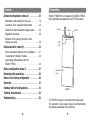
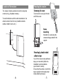
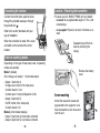
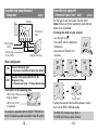
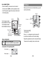
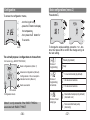
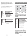
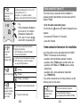
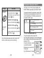
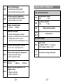
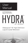
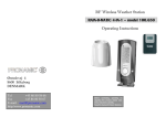
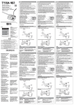
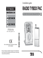
Installation guide
RADIO TYBOX PAC
Wireless programmable thermostat for heat pumps
RADIO TYBOX
Device compliant with the requirements of directives:
R&TTE 1999/5/CE
*2701907_rev1*
DELTA DORE - Bonnemain
35270 COMBOURG - FRANCE
E-mail : [email protected]
Because of changes in standards and equipment, the characteristics
given in the text and the illustrations in this document are not binding
unless confirmed by Delta Dore.
Warnings
Contents
Carefully read these instructions prior to installation.
• The unit must be installed in compliance with
currently applicable standards.
• Always switch off the mains before installing or
servicing the unit.
• Do not attempt to repair the unit yourself; an aftersales service is available.
• Check that the fastenings are suited to the surface
that the unit will be attached to (plasterboard, brick,
etc.).
• The diagrams provided are simplified for greater
clarity. The protective units and other accessories
required by the standards are not illustrated.
Standard UTE NF C15-100 and good practice must
be complied with. Connected or nearby equipment
must not generate excessive interference (directive
2004/108/EEC).
-2-
Presentation . . . . . . . . . . . . . . . . . . . . . . . . . .
Location of the receiver . . . . . . . . . . . . . . . . . .
Mounting the receiver . . . . . . . . . . . . . . . . . . .
Connecting the receiver . . . . . . . . . . . . . . . . . .
Receiver operating modes . . . . . . . . . . . . . . . . .
Location / Mounting the transmitter . . . . . . . . .
5
6
7
8
8
9
Screw-fitting . . . . . . . . . . . . . . . . . . . . . . . . . . . . . . . 9
Fitting to the base . . . . . . . . . . . . . . . . . . . . . . . . . 10
Non-reversible heat pump . . . . . . . . . . . . . . . . 11
Reversible heat pump
With thermostat input + change-over . . . . . . . . . . 12
With 2 thermostat inputs (cool - heat) . . . . . . . . . . 13
Starting up . . . . . . . . . . . . . . . . . . . . . . . . . . 15
Configuration . . . . . . . . . . . . . . . . . . . . . . . . . 16
Basic configurations (menu 1) . . . . . . . . . . . . 17
Choice of programming . . . . . . . . . . . . . . . . . . . . .
Choice of programming increments . . . . . . . . . . .
Choice of heat pump type . . . . . . . . . . . . . . . . . . .
Controlling the comfort temperature . . . . . . . . . . .
Circulator anti-seizing . . . . . . . . . . . . . . . . . . . . . .
-3-
17
17
17
18
18
Contents
Presentation
Advanced configurations (menu 2) . . . . . . . . . 19
Modification authorization for the user . . . . . . . . .
Correction of the measured temperature . . . . . . .
Automatic mode temperature display option . . . . .
Regulation time base . . . . . . . . . . . . . . . . . . . . . .
Selection of the opening direction of the
change-over relay . . . . . . . . . . . . . . . . . . . . . . . . .
19
20
20
20
20
Radio association (menu R) . . . . . . . . . . . . . . 21
RADIO TYBOX PAC is composed of a RADIO TYBOX
PAC transmitter associated with an RF 652 receiver.
Antenna
Button
ON LED
HEAT
LED
Home automation features on the installation . . . . 21
“Consumption indication” feature . . . . . . . . . . . . . 22
Associating radio products with the
RADIO TYBOX . . . . . . . . . . . . . . . . . . . . . . . . . . . 23
Option configuration (menu 3) . . . . . . . . . . . .
Removing radio associations . . . . . . . . . . . . . .
Return to the factory configuration . . . . . . . . .
Radio test . . . . . . . . . . . . . . . . . . . . . . . . . . .
Summary table of configurations . . . . . . . . . . .
Technical characteristics . . . . . . . . . . . . . . . . .
Troubleshooting . . . . . . . . . . . . . . . . . . . . . . .
-4-
27
29
30
31
31
34
36
Removable
cover
RF 652
The RF 652 receiver is connected to the heat pump
The elements of your system (receiver and transmitter)
are already associated when delivered.
-5-
Location of the receiver
The receiver must be positioned near the heat pump
control unit (e.g. Hydraulic module).
Mounting the receiver
Removing the cover
2
To remove the cover, push the tab
and lift the cover.
To avoid interference with the radio transmission, the
antenna must be free from any metallic elements
(cables, metallic covers, etc.).
1
Screwmounting
Mounted on a wall using the
screws and pegs suited to the
support
Mounting by double-sided
adhesive tape
If you fit the receiver using adhesive
tape, you must strictly follow the
installation recommendations
(see “location” section).
Ensure that the surface on which the
tape is applied is thoroughly clean
before attaching the tape.
-6-
-7-
Connecting the receiver
Location / Mounting the transmitter
For easier use, the RADIO TYBOX can be installed:
- on a wall: at an approximate height of 1.5 m, with
screws/plugs,
Connect the control wires, pass the wires
through the provided raceway or through
the pierced hole 1 .
- on a support: Placed on an item of furniture or a
shelf.
Refer to the section that deals with your
type of installation.
1
When the connection is made, fit the cover
and switch on the current at the circuit
breaker.
Separate the unit from its
base by unlocking the
casing.
Receiver operating modes
Depending on the type of heat pump used, 2 operating
modes are possible.
Remove the battery
cover.
Mode 1 (default)
One change-over output + 1 thermostat output
- Output 1 (terminal 4):
Change-over control of the heat pump
Contact closed = Cool
Contact open = Heat (Configuration 2-09)
- Output 2 (terminal 5):
On/Off control of the heat pump
Contact closed = On
Mode 2 (2 thermostat outputs)
- Output 1 (terminal 4): Heat mode command
- Output 2 (terminal 5): Cool mode command
-8-
Screw-mounting
Mount the base with screws and
pegs suited to the support or on a
flush-mounted box, then close and
lock the unit.
-9-
Fitting to the base
Non-reversible heat pump
Position the unit on its base and lock it.
1 Position the thermostat
on its base.
Do not wire
the output S1
2 Lock the thermostat
Mode 1
RF 652
230 V
Com
S1
S2
1 2 3 4 5
Thermostat
input
Power supply
230 V
- Menu configuration
Modifying the positions of the receiver’s outputs
1-06
Choice of the heat pump type
1 = Non-reversible heat pump (heat only)
If necessary, the On position for the thermostat output
can be switched around. To do this:
click
HEAT
ON
HEAT
RF 652
ON
RF 652
Press the button for approximately 10 seconds
until the relay status changes
Mode 1 : Modification of the On position for the output S2
Mode 2 : Modification of the On positions for outputs S1
and S2
- 10 -
- Description of the operating LEDs
LED is lit up if heat
mode is enabled
HEAT
ON
RF 652
LED is lit up if “On”
is requested
The receiver is associated with the RADIO TYBOX
802 in mode 1 by default
(see radio association/ menu R section)
- 11 -
Reversible heat pump thermostat
+ change-over
Mode 1
RF 652
230 V
Com
S1
S2
Thermostat
input
1 2 3 4 5
Power supply
230 V
Heat pump relay
common contacts
Change-over input
Reversible heat pump with
2 thermostat inputs (cool / heat)
Mode 2
For this type of use, the receiver must be set to
mode 2 before wiring the heat pump’s heat and cool
inputs on the thermostat.
To change the mode on your receiver:
- turn the knob to ,
- Press the i button to display the
temperature
- then press the i button for 5
seconds.
5 sec.
- Menu configuration
1-06
Choice of heat pump type
0 = Heat cool reversible heat pump (by default)
2-09
Selection of the opening direction for the
change-over relay
0 = Closed in cool mode - 1 = Closed in heat mode
RF 652
HEAT
ON
- Description of the operating LEDs
LED is lit up if heat
mode is enabled
HEAT
ON
RF 652
Choose mode 2
RF 652
LED is lit up if “On”
is requested
The receiver is associated with the RADIO TYBOX 802 in
mode 1 by default (see radio association/ menu R section)
- 12 -
Pressing the receiver button switches between mode 1
and 2. Let the HEAT LED flash rapidly.
The HEAT LED flashes slowly: Mode 1
The HEAT LED flashes rapidly: Mode 2.
- 13 -
On the RADIO TYBOX:
- Pres the button i, the receiver is set to mode 2
- Turn the knob to AUTO to exit the association mode
- Cut off the power supply to the receiver and connect
it to the heat pump.
Starting up
When you turn the unit on for the first time, you will
need to set the time.
Minutes
Days
RF 652
The S1 output controls
the thermostat’s cool input.
The S2 output controls
the thermostat’s heat input.
230 V
(1 : Monday… 7 : Sunday)
Com
S1
S2
1 2 3 4 5
Hours
Thermostat
cool input
Power supply
230 V
Turn the knob to
The days flash.
Heat pump relay
common contacts
Thermostat heat input
Press + or - to change the day, then press OK
to confirm and continue on to the next setting.
Repeat the operations to set the hours and minutes.
- Menu configuration
1-06
.
Choice of heat pump type
0 = Heat cool reversible heat pump (default)
To leave the “time setting” mode, turn the knob.
- Description of the operating LEDs
Cool request
Heat request
HEAT
ON
RF 652
- 14 -
- 15 -
Configuration
Basic configurations (menu 1)
To access the configuration menus,
Press button 1,
- turn the knob to
,
- press the i button to display
the temperature
- then press the i button for
5 seconds.
5 sec.
To change the various settings, press the + or - buttons, then press OK to confirm the change and go to
the next setting.
The unit will propose 4 configurations to choose from:
Weekly (by default)
Unit version (e.g. RADIO TYBOX 802)
Basic configurations (Menu 1)
Choice of
programming
Advanced configurations (Menu 2)
Configurations of the consumption
indication function (Menu 3)
Radio association
1-hour increments (by default)
Choice of
programming
increments
Unit version
Configuration mode
Menu 3 is only accessible if the RADIO TYBOX is
associated with RADIO TYWATT.
- 16 -
Daily
Choice of heat
pump type
30-minute increments
15-minute increments
Reversible heat pump (by default)
(heat and cool)
Non-reversible heat pump
(heat only)
- 17 -
For hot water heaters with thermostatic valves, the
Comfort temperature can be provided by adjusting the
thermostat of each radiator.
In this case, only Economy and Frost Protection temperatures are set by the RADIO TYBOX.
Advanced configurations (menu 2)
Comfort temperature set by the
TYBOX (by default)
Controlling the
Comfort
temperature
Comfort temperature controlled by
each radiator or fan coil unit.
Here, the display reads ConF
during Comfort period.
Press button 2.
To change the various settings, press the + or - buttons, then press OK to confirm the change and go to
the next setting.
Anti-seizing disabled (default)
Circulator
anti-seizing
Anti-seizing enabled
(circulator operates for 1 minute
every 24 hours)
Modification
authorization
for the user
Program and temperature settings
(from 5 to 30°C) modification authorized
Program and set-point setting
modification unauthorized
(Heat comfort: 16 to 22°C,
Cool comfort: 21 to 27°C,
Warm economy: 13 to 19°C,
Cool economy: 24 to 30°C)
If there is a difference between the temperature noted
(thermometer) and the temperature measured and
displayed by the unit, function 2-02 modifies the way
the probe takes measurements so as to compensate
for this difference.
- 18 -
- 19 -
Correction of the
measured
temperature
Correction possible from -5°C to +5°C
in increments of 0.1°C.
Press the + or - buttons to make
changes, and confirm with the OK button.
E.g.
If the temperature displayed
by the unit is 19°C and the
temperature measured is
20°C, add 1°C to the display
and confirm by pressing OK.
Automatic
mode
temperature
display option
Continuous set-point temperature
display (by default).
With this option, press i to display
the room temperature.
Continuous room temperature display.
With this option, press i to display t
he set-point temperature.
minutes
Control time base
minutes
minutes (by default)
Radio association (menu R)
This menu lets you associate all the installation’s
wireless products (transmitters and receivers) with the
RADIO TYBOX.
Go to the radio association menu
Turn the knob to , press the i button to display the temperature
- then press the i button for 5 seconds.
- press the R button.
Home automation features on the installation
Up to 8 products can be associated with the RADIO
TYBOX. The features are the following:
- operation with door/window magnetic contacts,
- operation with a TYXAL alarm central control unit
- operation with TYXAL or TYDOM remote controls
(Delta Dore),
- operation with a home automation transmitter
(e.g. TYDOM 310).
If you wish to associate one of these products, set the
following menu to the value 1.
Closed in Cool mode (by default)
Selection of the
opening direction
for the change
-over relay
No home automation features
Closed in Heat mode
- 20 -
Home automation
features on the
installation
Home automation features
associated with the RADIO TYBOX
- 21 -
Press + or - to make your choice.
Press OK to confirm and go to the next mode.
“Consumption indication” feature
Radio association (menu R)
Associating radio products with the RADIO
TYBOX
From the menu rAd.
To associate a consumption indicator with the RADIO
TYBOX (e.g. RADIO TYWATT).
No consumption indication
Consumption
indication function
Consumption indicator to associate
Press + or - to display
1 flashing.
Confirm on the RADIO TYWATT.
Check on the RADIO TYBOX that
flashing.
1 is no longer
The RADIO TYBOX and the RADIO TYWATT are associated.
- 22 -
1st step: the receiver is delivered already associated
with the transmitter.
The display indicates “rAd” as well as the number of
associated products (1 receiver).
You can go straight on to the 2nd step,
Associating the home automation products.
To associate a wireless receiver again, you must first
remove all associations (see Removing radio
associations section), then, on the receiver:
for three seconds, press and hold the button on the
receiver you wish to associate.
The corresponding LED flashes.
On the RADIO TYBOX,
press the i. button.
The screen displays 1.
The receiver is associated
with the RADIO TYBOX.
- 23 -
2nd step: Associating the home automation products.
On the home automation
product to associate, confirm
the association as indicated in
the table or refer to its user
guide.
Each newly associated
product is displayed on the
screen.
Number of associated
transmitters
Product
Product
1
2
3
4
5
6
7
8
9
0
#
Remote control of
the installation
TYXAL control unit
Association
Press the button.
Monitoring
alarm on:
Heating in
Economy
mode
Heating in
Economy mode
Monitoring alarm off:
Heating in Comfort
mode
(override in AUTO
mode)
Enter the first 4 numbers of the access
code (1234 by default), then press the
( ) button for 5 seconds.
Set the control unit to maintenance mode
before switching the RADIO TYBOX to
radio association (menu rAd).
Simultaneously press and hold the ON and
OFF buttons of the unit’s control device for
5 seconds to switch to maintenance mode.
Open the cover of the control unit and
press the “test” button.
Close the control unit.
Outside
sensor
TYXIA remote control
Simultaneously press and hold the buttons
Comfort or Economy
overrides.
Association
Telephone
transmitter
Press OK to confirm
Door/window
magnetic
contact
Open
Window:
- Heat mode: heating in
frost protection mode
- Cool mode : Cooling
is shut down
Radio association (menu R)
for 5 seconds, le LED comes on,
goes off, and then comes back on, release
the buttons.
- 24 -
Indication
of the outside
temperature
(without optimization)
Press the association button,
the LED switches on then off.
Close the sensor unit.
- 25 -
Configuration des options (menu 3)
Product
Home automation
remote control
The menus 3-12 to 3-18 are only accessible if the
RADIO TYBOX is associated with a RADIO TYWATT.
Association
Press the domain button until
until the remote control emits a beep and
the symbol
flashes.
Associate the buttons
and
Press one of the tactile buttons
Associate the buttons
Comfort / Economy
and/or ON / OFF
overrides
To access the display of consumption, heating, DHW
and other uses, you must declare the number of CTs
(current transformers, ref. 6330004) associated with
the RADIO TYWATT option.
or
No consumption indication
(by default)
.
Number of CTs
1 CT (Heating)
and
Press one of the tactile buttons
or
.
To exit the association mode, press another
domain button (e.g.
).
Once the radio associations are made, press the OK
button to confirm and go on to the next mode.
2 CTs (Heating + DHW)
Not used
3-13 à 3-18 Coût du Kwh (TTC)
The price displayed is the price per kWh
(excl. subscription) expressed in euros including taxes
(price including municipal and regional taxes and VAT
(average of 30%).
For further information, contact
your electricity provider.
We advise you to round to the
nearest cent.
E.g. 0.1085 euros is 0.11 euros.
0.11 euros (incl. tax)
- 26 -
- 27 -
Configurations 3-13 to 3-18 let you modify costs
according to your subscription.
Subscription
option
Removing radio associations
Base
Double tariff
tempo
EJP
Base
OP
OP blue day
Normal
hours
-
PH
PH blue day
Peak
hours
-
-
white day OP
-
-
-
white day PH
-
-
-
red day OP
-
-
-
red day PH
-
To cancel all radio associations, turn the knob to ,
then hold the i button down for 5 seconds. (this
action also removes the displayed consumption information).
PH: Peak Hours, OP: Off-peak Hours
IMPORTANT: The consumption value that you can
read on the digital screen is a non-contractual
indication and cannot be substituted with the
consumption value mentioned on your electricity bill..
After menu 3 has been configured, the unit returns to the
choice of menus.
To exit the configuration, turn the knob to the right.
- 28 -
Press and hold the
R button for 5 seconds.
Then press the OK button
to confirm the reset.
To associate the receiver with the transmitter again,
refer to the “radio association” section.
Manually resetting the receiver:
Press the receiver button for 30 seconds until the
HEAT LED flashes rapidly.
- 29 -
Return to the factory configuration
A return to the factory configuration is possible for
menus 1, 2, and 3.
Turn the knob to , then press and hold the i button
for 5 seconds.
Radio test
Turn the knob to , then hold the 2nd button (from the
top) down for 5 seconds until tESt appears.
5 sec.
Press the button of the menu
you wish to reset, and hold
the button for 5 seconds
(this example uses menu 1).
The HEAT LED on the receiver should flash for each
reception (approximately every 6 seconds).
If this happens, radio transmission is occurring correctly.
Then press the OK button to
confirm the reset..
If this does not occur, move your transmitter.
Turn the knob or press the OK button to exit the tESt
mode.
Summary table of configurations
Follow the same steps for the other menus.
To exit this mode, turn the knob to the right.
- 30 -
1-01
Type of programming
0 = weekly
1-02
Pas de programmation
0 = 1 hour
1 = 30 minutes
- 31 -
1= daily
2 = 15 minutes
1-06
1-08
1-09
2-01
Choice of heat pump type
0 = reversible heat pump (by default)
1 = Non-reversible heat pump (heat only)
Controlling the Comfort temperature
0 = set by the RADIO TYBOX (by default)
1 = by each radiator or fan coil unit.
Circulator anti-seizing feature
0 = Disabled
1 = Enabled
Modification authorization
0 = Program and settings may be changed
1 = Program not modifiable and set-point temperature
settings limited (Comfort: 16 to 22°C
Economy: 13 to 19°C, Frost Protection: 5 to 11°C)
2-02
Correction of the temperature measured
by -5°C to +5°C in increments of 0.1°C.
2-04
Automatic mode temperature display option
0 = Set-point temperature display
1 = Room temperature display
2-08
Control time base
30 Minutes
45 Minutes
2-09
Selection of the opening direction for the
change-over relay
0 = Closed in cool mode
1 = Closed in heat mode
- 32 -
Summary table of configurations
Radio association (menu R)
r-01
Home automation features
0 = No
1 = Yes
r-02
Consumption indication
0 = No
1 = Yes
rAd
Radio products association
Zone
rAd 1
Reserved menu
With a RADIO TYWATT
3-12
Number of CTs
0 = No RADIO TYWATT 1 = 1 CT (Heating)
2 = 2 CTs (Heating + DHW) 3 = 3 CTs
3-13
to
3-18
Cost per kWh according to subscription
60 Minutes
- 33 -
Technical characteristics
Technical characteristics
RADIO TYBOX transmitter
RF 652 receiver
• Power supplied by two LR03 or AAA-type 1.5 V
alkaline batteries (supplied), autonomy of 2 years for
normal use
• Class III insulation
• Clock back-up in the event of battery change: 30
seconds
• Radio range 100 to 300 metres outside, variable
depending on the associated equipment (the range
can be altered depending on the installation
conditions and the electromagnetic environment)
• Radio frequency 868 MHz, class I (standard EN 300
220)
• Radio remote control device
• Dimensions: LxHxD = 80 x 103 x 16 mm
• Protection index: IP 40
• Storage temperature: -10°C to +70°C
• Operating temperature: 0°C to +40°C
• Installation in an environment with normal pollution
levels
• Mounting with screws or on a support
• Minimum time for triggering the outputs:
10% of the time base (see menu 2-08).
• 230 V, 50 Hz power supply, +/-10%
- 34 -
• Class II insulation
• Power consumption: 0.5 VA
• Maximum power: 3A 230 Veff Cos ? = 1
Î Radio frequency 868 MHz, class 1
(Standard EN 300 220),
• Radio remote control device
• Radio range 100 to 300 metres outside, variable
depending on the associated equipment (the range
can be altered depending on the installation
conditions and the electromagnetic environment)
• Automatic action: type 1.C
• Storage temperature: -10 to +70°C
• Operating temperature: 0°C +40°C,
• Dimensions: 120 x 54 x 25 mm
• Protection index: IP 44 - IK 04
• Install in an environment with normal pollution levels.
- 35 -
Troubleshooting
Nothing is displayed on the room unit screen.
There is no power supply
Check the batteries.
The receiver does not accept orders from the transmitter.
• Check the transmission by performing a radio test.
• Move your transmitter if necessary.
• Repeat the radio-controlled association of the receiver with
the RADIO TYBOX.
The indication
is displayed.
The batteries are low.
Change the batteries, making sure they are the right way
round.
The unit displays: dEF 6.
There is a communication fault between the RADIO TYBOX
and the RF 652 receiver.
Check the installation.
You wish to associate a home automation feature and the
screen displays ---- .
You have reached the maximum number of functions to associate.
During the radio association, then device displays:
Zone rAd 1.
This menu is reserved.
Associate the receiver again from the rAd menu.
The device displays “CONF”.
The parameter 1.08 is set to 1.
The setting is controlled by each radiator or coil fan.
- 36 -
- 37 -
- 38 -
- 39 -