1
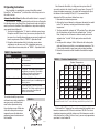
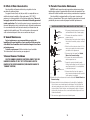
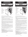
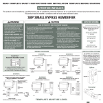
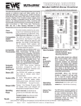
Limited Warranty (continued from page 15)
READ AND SAVE THESE
INSTRUCTIONS
WARRANTY CONDITIONS:
1. To obtain the longer warranty periods as shown in the table under original owner, for the original
purchaser, the product must be properly registered at www.cac-bdp.com within ninety (90) days of
original installation. In jurisdictions where warranty terms conditioned on registration are prohibited
by law, registration is not required and the longer warranty period shown will be apply.
2. Where a product is installed in a newly constructed home, the date of installation is the date the
homeowner purchased the home from the builder.
3. If the date of original installation cannot be verified, then the warranty period begins ninety (90) days
from the date of product manufacture (as indicated by the model and serial number). Proof of
purchase may be required at time of service.
4. The remainder of the first five years of warranty is freely transferable without registration. To obtain
a transfer of the longer warranty periods as shown in the table under subsequent owner, a
subsequent owner must register the transfer at www.cac-bdp.com within 90 days of the change in
ownership and payment of a transfer fee. Not applicable in all jurisdictions. See website for details.
5. Product must be installed properly and by a licensed HVAC technician.
6. The warranty applies only to products remaining in their original installation location.
7. Installation, use, care, and maintenance must be normal and in accordance with instructions
contained in the Installation Instructions, Owner’s Manual and Company’s service information.
8. Defective parts must be returned to the distributor through a registered servicing dealer for credit.
LIMITATIONS OF WARRANTIES: ALL IMPLIED WARRANTIES AND/OR CONDITIONS (INCLUDING
IMPLIED WARRANTIES OR CONDITIONS OF MERCHANTABILITY AND FITNESS FOR A PARTICULAR
USE OR PURPOSE) ARE LIMITED TO THE DURATION OF THIS LIMITED WARRANTY. SOME STATES OR
PROVINCES DO NOT ALLOW LIMITATIONS ON HOW LONG AN IMPLIED WARRANTY OR CONDITION
LASTS, SO THE ABOVE MAY NOT APPLY TO YOU. THE EXPRESS WARRANTIES MADE IN THIS
WARRANTY ARE EXCLUSIVE AND MAY NOT BE ALTERED, ENLARGED, OR CHANGED BY ANY
DISTRIBUTOR, DEALER, OR OTHER PERSON, WHATSOEVER.
THIS WARRANTY DOES NOT COVER:
1. Labor or other costs incurred for diagnosing, repairing, removing, installing, shipping, servicing or
handling of either defective parts, or replacement parts, or new units.
2. Any product purchased over the Internet.
OWNER’S MANUAL
FOR BYPASS AND FAN POWERED HUMIDIFIERS
3. Normal maintenance as outlined in the installation and servicing instructions or Owner’s Manual,
including filter cleaning and/or replacement and lubrication.
4. Failure, damage or repairs from faulty installation, misapplication, abuse, improper servicing,
unauthorized alteration or improper operation.
5. Failure to start due to voltage conditions, blown fuses, open circuit breakers, or damages due to the
inadequacy or interruption of electrical service.
6. Failure or damage due to floods, winds, fires, lightning, accidents, corrosive environments (rust, etc)
or other conditions beyond the control of Company.
Type Installed:
Maintenance page:
7. Parts not supplied or designated by Company, or damages resulting from their use.
Small or Large Bypass
12
8. Products installed outside the U.S.A. or its territories and Canada.
Water Saver Bypass
13
Fan Powered
14
9. Electricity or fuel costs, or increases in electricity or fuel costs from any reason whatsoever, including
additional or unusual use of supplemental electric heat.
10. Any cost to replace, refill or dispose of refrigerant, including the cost of refrigerant.
11. ANY SPECIAL, INDIRECT OR CONSEQUENTIAL PROPERTY OR COMMERCIAL DAMAGE OF ANY
NATURE WHATSOEVER. Some states or provinces do not allow the exclusion of incidental or
consequential damages, so the above limitation may not apply to you.
This Warranty gives you specific legal rights, and you may also have other rights which vary from state
to state or province to province.
39004DP462
01/10
Includes Safety, Operating and Maintenance Instructions
©2010 CAC/BDP
7310 West Morris St., Indianapolis, IN 46231
Form/Catalog: OG-HUMWBP-02
10008882 1.10
B2205060A
16
Replaces OG-HUMWBP-01
OG-HUM-04
Bypass and Fan Powered Humidifiers
Table of Contents
WARNING! 120 VOLTS may cause injury from electrical shock.
Disconnect power and shut off water supply before servicing.
Page
Introduction . . . . . . . . . . . . . . . . . . . . . . . . . . . . . . . . . . . . . . . . . . . . . . . . . . . . 3
Principle of Operation . . . . . . . . . . . . . . . . . . . . . . . . . . . . . . . . . . . . . . . . . . . . 4
CAUTION! Sudden operation may cause personal injury or
property damage. Turn Humidifier Control to “OFF” before
servicing.
Operating Instructions . . . . . . . . . . . . . . . . . . . . . . . . . . . . . . . . . . . . . . . . . . . 6
Effect of Water Characteristics . . . . . . . . . . . . . . . . . . . . . . . . . . . . . . . . . . 10
Annual Maintenance. . . . . . . . . . . . . . . . . . . . . . . . . . . . . . . . . . . . . . . . . . . . 10
Annual Summer Shutdown . . . . . . . . . . . . . . . . . . . . . . . . . . . . . . . . . . . . . . 10
Periodic Preventative Maintenance . . . . . . . . . . . . . . . . . . . . . . . . . . . . . . 11
Maintenance Instructions
Introduction
Thank you for your humidifier purchase. We sincerely appreciate your
business and are pleased to add your name to our growing list of
customers. Now, please take a few minutes and read this booklet. This
will familiarize you with the benefits you will receive from the
equipment you have purchased and help you understand the routine
maintenance that will be required.
Small and Large Bypass Humidifiers . . . . . . . . . . . . . . . . . . . . . . . . . . . . . 12
Water Saver Humidifier . . . . . . . . . . . . . . . . . . . . . . . . . . . . . . . . . . . . . . . . . 13
Fan Powered Humidifier . . . . . . . . . . . . . . . . . . . . . . . . . . . . . . . . . . . . . . . . 14
Limited Warranty . . . . . . . . . . . . . . . . . . . . . . . . . . . . . . . . . . . . . . . . . . . . . . . 15
2
3
I. Principle of Operation
You have purchased a humidifier that operates on the evaporative
principle. It will provide the proper relative humidity (see operating
instructions) all during the heating season. It is very possible that you
have questions concerning what your humidifier can do for you, and
what you should do to receive maximum benefits from it. This booklet is
intended to answer these questions.
The humidifier operates in conjunction with the furnace blower
motor. When the humidifier control calls for humidity and the blower
motor is operating, water flows to the distribution tray located at the top
of the humidifier. The water is uniformly distributed across the width of
the tray and through a scientifically designed system of outlets. It flows
by gravity over the humidifier pad. Dry, hot air is moved through the
moisture-laden humidifier pad where evaporation takes place. The
now-humidified air carries moisture in vapor form throughout the home.
The correct water flow is determined by an orifice in each
humidifier. When the humidifier is operating, there will be a small,
steady stream of water to drain, which flushes away most of the
trouble-causing minerals. Do not use the saddle valve to regulate the
water flow. It is designed to be completely opened or closed.
The minerals and solid residue not trapped by the replaceable
humidifier pad are flushed down the drain. The drain also eliminates the
problems caused by stagnant water. This is the most effective and least
expensive method to dispose of trouble-causing minerals.
Trouble-free performance and minimum maintenance are assured
by the design features of the humidifier. All humidifier housing parts that
come in contact with water are non-metal (except for the valve and
humidifier pad) and will never rust or corrode. Neither heat nor water
will affect them under normal operating conditions.
4
The humidifier pad, designed especially for uniform, high
evaporation, and the Scale Control Insert also efficiently trap mineral
deposits which are often the cause of damage to working parts in
ordinary humidifiers. No “white dust” can be distributed throughout the
living quarters. The humidifier pad must be in good condition to assure
high capacity trouble-free performance. It should be changed annually
with the exception of the Water Saver humidifier which should be
replaced at least twice per heating season.
Older design water distribution trays have a granular coating in the
bottom of the distribution tray to provide equal distribution of water to
each of the openings assuring an even flow over the humidifier pad. Do
not clean the mineral scale off the bottom of the water distribution tray
at the end of the humidification season. If the granular coating is
removed, it is not necessary to purchase a new distribution tray. You
can accomplish the same uniform performance by applying a small
amount of liquid dishwashing soap over the entire inside surface of the
water distribution tray. This will allow the water to flow evenly through
each of the openings, provided the humidifier is level, in order to
achieve maximum capacity.
The current distribution tray which incorporates a synthetic fabric
liner that replaces the granular coating, is designed to deliver water
uniformly over the entire top surface of the humidifier pad, provided it is
mounted level. It is normal for some mineral deposits to form in the
distribution tray as it dries out between humidification cycles. These
deposits can actually help distribute water in the tray, but if they form
enough to block the openings, they should be removed as described in
the “Periodic Preventative Maintenance” section of this manual.
5
II. Operating Instructions
Your humidifier is controlled by a manual humidifier control,
HumidiTrac™ or Thermidistat™, installed either in the living area or in
the cold air return.
Automatic Humidifier Control: (for Manual Humidifier Control – see page 8)
Your HumidiTrac™ Control is installed in the cold air return. During the
first heating season, your HumidiTrac™ Control needs to be set initially to
match your home’s condition. Please follow these steps when adjusting
your control (refer to Figure A).
1. Turn the dial setting knob to “5,” which is within the normal range.
During the next 24-48 hours it may be necessary to adjust the dial
for more or less humidity, depending on your personal comfort and
home’s requirements. Refer to “TABLE 1 – Operation Guide”.
2. During the coldest portion of the first heating season, minor
adjustments may be necessary. This is dependent upon your
individual home construction, refer to “TABLE 1 – Operation Guide”.
TABLE 1 – Operation Guide
Condition
Solution
Reduce the setting on the control dial
by 1 increment.
Lack of humidity
Increase the setting on the control dial
by 1 increment.
Humidifier does not operate
Turn dial to “Test.” Make certain furnace
and blower are operating. If humidifier
still doesn’t operate, consult your air
conditioning and heating dealer.
TABLE 2 – % Relative Humidity Guide
Outdoor Temperature
-10°F 0°F 10°F 20°F 30°F
-23°C -18°C -12°C -7°C -1°C
Humidifier won’t shut off
Turn dial to “Off.” If humidifier continues to
operate, consult your air conditioning and
heating dealer.
Test mode
System operation is checked by setting
the knob to “Test.” Make certain furnace and
blower are operating. Humidifier will
operate for one minute.
The relative humidity in your home
will now be accurately controlled to
meet your needs and should not
need further adjustment during
future heating seasons. Make note
of the dial setting in the event you
temporarily move the knob when
performing annual maintenance of
the Humidifier.
FIGURE A
Dial Setting
Condensation on windows
Your Automatic Humidifier, is a high precision system that will
accurately maintain the relative humidity in your home. For every 1°F
change in outdoor temperature, the control will automatically adjust
the indoor relative humidity (RH) by 1/2%. If you would like to
determine the RH in your home, follow these steps:
1. Determine the outdoor temperature.
2. Activate the furnace blower by setting your thermostat fan switch
to the “On” position, or setting your thermostat to a higher
temperature.
3. Turn the control dial setting to the “Off” position. Then, slowly turn
the dial clockwise until you hear the solenoid valve “click on.”
Next, slowly turn the dial counter-clockwise until you hear the
solenoid valve “click off.” At this point, make note of the dial
setting.
4. Locate your dial setting on Table 2. Follow the dial setting to the
right until it intersects with the current outdoor temperature. This
is the relative humidity in your home under existing conditions.
5. Return the thermostat and the Humidifier Control to their original
settings.
1
10
10
10
15
20
25
2
10
10
15
20
25
30
3
10
15
20
25
30
35
4
15
20
25
30
35
40
5
20
25
30
35
40
45
6
25
30
35
40
45
45
7
30
35
40
45
45
45
As an example, if the outdoor temperature is 20°F, and, following step 3,
the humidifier turns off at “5” on the dial range, then the RH in your home is 35%.
The HumidiTrac™ Control will accurately control the humidity in your
home to a maximum of 45% RH and a minimum of 10% RH. The values
of outdoor temperature and dial settings may fall in between or outside
of the listed values in Table 2. In these cases, you can only approximate
your home’s actual indoor RH.
90-1054
6
40°F
4°C
7
To check the humidifier’s operation, note the current setting
and set the HumidiTrac™ Control to the Test mode when the furnace
blower motor is operating. Water will flow into the humidifier for
1 minute and then it will turn off. This insures the humidifier is
operating properly. Do not leave the control in the test mode as it
will not operate. Reset the control to it’s original setting.
Note: Turning the knob to “Test” resets the Humidifier Pad Change
Indicator timer.
Manual Humidifier Control or HumidiTrac™ in Manual Mode:
(for Automatic Humidifier Control – see page 6)
Your humidifier is controlled by a humidifier control installed either
in the living area (typically near the thermostat) or in the cold air return.
It is important to anticipate a drop in outdoor temperature and reduce
the setting accordingly to avoid excessive condensation. For example,
with an outdoor temperature of 20°F (-7°C) the correct setting will be
35% relative humidity. If the temperature is expected to fall to 0°F
(-18°C) that evening, then merely reduce the setting to 25% several
hours prior to the temperature change.
The recommended settings on the humidifier control are based on
years of research (see Table 3) and experience as to what is best for
the average home. These settings represent a compromise between RH
levels that would be most desirable for comfort reasons and humidity
levels that are suitable for protection of your home. For example, a
wintertime indoor RH of 50% may be considered ideal by some, but
unfortunately, it probably would result in damage to your home.
Observance of the recommended RH levels on your humidifier control,
therefore, is an important safeguard. Condensation of water on inside
windows in the form of fogging or frost is usually an indication that the
relative humidity is too high. This same condensation can take place in
other areas in your home with the possibility of damage resulting.
The Humidifier Control is a precision instrument that can be used
to determine the RH accurately in your home during the winter. Turn the
dial to the lowest setting, then reverse the dial direction slowly until a
“click” is heard. At this point, read the RH on the dial. This will be very
close to the actual RH in your home.
To check the humidifier operation, set the humidifier control
above the click point, make sure that the water saddle valve is open
and that there is electricity to the humidifier. Generally, the furnace
and blower motor must be operating for the humidifier control to
function. After the humidifier has operated for several minutes and
water is entering the humidifier and coming out at the drain, reduce
the humidifier control setting below the click point and the humidifier
should automatically shut off. Now set the humidifier control dial at
the recommended inside relative humidity, depending on the outside
temperature. Follow the suggested settings prior to a drop in the
outside temperature.
Additional Information
Be sure to keep fireplace dampers closed when not in use.
They provide an excellent escape route for heat, as well as humidity.
Humidity is lost at an even faster rate than heat because water vapor
tends to seek its own level and your humidifier would not be able to
replace it even when running at full capacity.
On occasion, indoor moisture producing activities such as clothes
drying, cooking, showers, etc., may raise the relative humidity level
higher than it should be, even though the Humidifier is not operating.
Telltale indications, again, are condensation or frost on cold surfaces
such as windows, doors, walls, etc. If such condensation persists for
several hours, your home should be ventilated to dissipate the
potentially damaging excess moisture.
TABLE 3 – Outdoor-Indoor Relative Humidity
Outside Temperature
Recommended RH
+40°F (4°C)
+30°F (-1°C)
+20°F (-7°C)
+10°F (-12°C)
0°F (-18°C)
–10°F (-23°C)
–20°F (-29°C)
45%
40%
35%
30%
25%
20%
15%
8
9
III. Effect of Water Characteristics
VI. Periodic Preventative Maintenance
Your humidifier will operate effectively using either hard or
mechanically softened water.
Any type of water (hard, soft, hot, or cold) is acceptable for use
with the drain-type humidifiers. Hot supply water, 125°F (52°C)
maximum, is recommended for all heat pump applications. The use of
hot supply water will also increase the amount of humidity generated
in other applications. The heat in the water increases evaporation and
the water going to the drain is cold to the touch. For better performance
it is recommended that soft (reduced minerals) or filtered water be
supplied to the humidifier pad. This can help reduce the amount of
scale and mineral deposits that can accumulate on the pad.
NOTE: Periodic inspection and preventative maintenance of your
total heating system is important for efficient and safe operation. Your
dealer will include humidifier service during a maintenance inspection.
Your humidifier is equipped with an in-line water strainer and
orifice as shown below. These parts should be inspected and cleaned
periodically to ensure continued proper humidifier performance.
WATER LINE INSPECTION AND SERVICE INSTRUCTIONS
WATER
FEED TUBE
OUTLET
COMPRESSION
NUT
IV. Annual Maintenance
For best performance, we recommend that you replace the
humidifier pad in your humidifier at least annually with the exception
of the Water Saver humidifier which should be changed at least twice
per heating season.
To obtain a replacement: Call the installer of your humidifier.
This information is often found on your equipment.
ORIFICE
SOLENOID
VALVE
INLET
V. Annual Summer Shutdown
FOR THE SUMMER HUMIDIFIER SHUTDOWN, SIMPLY TURN THE
HUMIDIFIER CONTROL TO THE “OFF” SETTING AND CLOSE THE
DAMPER IN THE BYPASS HUMIDIFIER. (TURN DAMPER HANDLE TO
“SUMMER” POSITION)
IN-LINE
STRAINER
INLET
COMPRESSION
NUT
90-1053
1. Disconnect electrical power to the furnace
and humidifier and shut off water supply.
2. Disconnect the water line at the inlet
compression nut.
3. Remove the in-line strainer from inside the
inlet side of the valve by using a small nail
or wire.
4. Flush the in-line strainer to clean it. If it is
necessary to replace the strainer, contact
your dealer for a replacement.
5. Reconnect the inlet water line. Double
Wrench to Prevent Leaking.
6. Disconnect the water feed tube at the
outlet compression nut.
7. Inspect the water feed tube by gently
flexing it and looking for cracks or signs of
wear. Replace tube if it is cracked, brittle,
or has been damaged.
8. Remove the orifice from the copper or
plastic water feed tube and make sure this
small opening is unplugged.
9. Replace the orifice and reconnect the water feed tube. Double Wrench to
Prevent Leaking.
10. Remove the drain line from the bottom of the humidifier. If applicable,
flex it to loosen any mineral deposits or blockages. Flush the drain line
with water under pressure to clear it of any debris, and slip it back onto
the drain fitting. If drain line does not clean properly, replace it. Inspect
the drain line to make sure it has a constant downward slope and is not
flattened or blocked.
11. Turn on water supply and reconnect electrical power.
10
11
MAINTENANCE INSTRUCTIONS FOR
SMALL AND LARGE BYPASS HUMIDIFIERS
MAINTENANCE INSTRUCTIONS FOR
WATER SAVER HUMIDIFIER
CAUTION
CAUTION
Sudden operation may cause personal injury or property damage.
Turn Humidifier Control to “OFF” or lowest setting before servicing.
4
Sudden operation may cause personal injury or property damage.
Turn Humidifier Control to “OFF” or lowest setting before servicing.
5
8
1. Front Cover
2. Feed Tube
6
7
1
3. Integral Bypass Damper
4. Evaporative Assembly
5. Distribution Tray
6. “V” Notches
7. Humidifier Pad
8. Scale Control Insert
9. Drain Line
2
3
9
1. Front Cover
2. Feed Tube
3. Integral Bypass Damper
4. Evaporative Assembly
5. Distribution Tray
6. “V” Notches
7. Humidifier Pad
8. Scale Control Insert /Float
Chamber
9. Overflow Drain Line
10. Float Cover
11. Float
12. Water Level Sensor Assembly
5
6
8
4
7
1
3
2
11
10
12
9
90-1077
90-1173
1. Note Humidifier Control setting and turn dial to the “OFF” position.
1. Note Humidifier Control setting and turn dial to the “OFF” position.
2. Turn off water supply. Turn the integral bypass damper (3) to the SUMMER position.
2. Turn off water supply. Turn the integral bypass damper (3) to the “SUMMER” position.
3. Press the tabs in the latches on the top and bottom of front cover (1) and pull cover off base with
both hands. Set aside.
3. Press the tabs in the latches on the top and bottom of front cover (1) and pull cover off base with
both hands.
4. Carefully pull the plastic feed tube (2) out of the distribution tray (5) at the top of the evaporative
assembly (4). Pull this assembly out by grasping at top and tipping out.
4. Carefully pull the plastic feed tube (2) out of the distribution tray (5) at the top of the evaporative
assembly (4). Tip the evaporative assembly forward and lift it out of the humidifier. Do not tip the
evaporative assembly more than needed to clear the housing to avoid over-bending the water level
sensor assembly (12).
5. Unsnap the distribution tray (5) from the scale control insert (8). Lightly scrape out or brush off
any mineral deposits, being careful not to stretch or loosen the synthetic fabric liner. Soaking
the tray in vinegar or a lime-removing agent is helpful when trying to remove stubborn mineral
deposits.
6. Slide the Humidifier Pad (7) out from the scale control insert (8). Clean the scale control insert
of mineral deposits. Replace the Humidifier Pad (Part No. P110-1045 for Small Bypass Humidifier
and Part No. P110-3545 for Large Bypass Humidifier) with a new Humidifier Pad. Slide the
Humidifier Pad back into the scale control insert with the colored spot up and snap the
distribution tray (5) back into place.
7. Inspect the plastic feed tube (2) by gently flexing it and looking for cracks or signs of wear.
Replace tube if it is cracked, brittle, or has been damaged.
8. Reinstall the evaporative assembly (4) into the humidifier by fitting its drain into the round
receptacle at the base of the humidifier. Push the assembly in at the top until it snaps into place.
Push the end of the feed tube back firmly into the distribution tray and replace the front cover.
9. Remove the drain line (9) from the bottom of the humidifier. If applicable, flex it to loosen any
mineral deposits or blockage. Then flush it with water under pressure. If it does not properly
clear, replace it. Slip drain line back onto the drain fitting. Make sure the drain line has a
constant downward slope and is not flattened or blocked.
10. Turn on the water supply. Return integral bypass damper to appropriate position.
11. Check system operation:
Manual Humidifier Control: With the furnace blower operating and the furnace calling for heat,
turn up Control and check system operation.
Humiditrac™ Humidifier Control: (Automatic or Manual mode) Check system operation and
reset Change Humidifier Pad indicator by setting the knob to “Test/Reset”. With furnace blower
operating and furnace calling for heat, humidifier will operate for one minute. DO NOT LEAVE IN
TEST MODE AS HUMIDIFIER WILL NOT OPERATE.
12. Set Humidifier Control to its original position.
5. Unsnap the distribution tray (5) from the scale control insert (8). Lightly scrape out or brush off any
mineral deposits, being careful not to stretch or loosen the synthetic fabric liner. Soaking the tray
in vinegar or a lime-removing agent is helpful when trying to remove stubborn mineral deposits.
6. Slide the used Humidifier Pad (7) out of the scale control insert/float chamber and dispose of it.
7. Remove the float cover (10) and inspect the floats (11) and float chamber for mineral build-up.
Remove deposits as needed from floats, float chamber and scale control insert. Wash the parts
with a disinfecting cleaner. Reassemble the floats and float cover. Make sure stems of both floats
extend through openings in float cover and that floats move freely up and down.
8. Inspect the plastic feed tube (2) by gently flexing it and looking for cracks or signs of wear. Replace
tube if it is cracked, brittle, or has been damaged.
9. Slide a new Humidifier Pad Part No. P110-4545 (7) into the scale control insert/float chamber (8).
Snap the distribution tray (5) back on the scale control insert (8). Note: using non-recommended
pads may result in leaks or improper operation.
10. Reinstall the evaporative assembly (4) into the humidifier. Take care not to over-bend the water level
sensor assembly. Push the top of the evaporative assembly firmly back until it snaps into place.
11. Push the end of the feed tube back firmly into the distribution tray. Replace the front cover.
12. Under normal operation the overflow drain line (9) will never have water in it. However, inspect it
for mineral deposits and replace if necessary. Make sure the drain line has a constant downward
slope and is not flattened or blocked.
13. Turn on the water supply. Return integral bypass damper to appropriate position.
14. Check system operation:
Manual Humidifier Control: With the furnace blower operating and the furnace calling for heat,
turn up Control and check system operation.
Humiditrac™ Humidifier Control: (Automatic or Manual mode) Check system operation and
reset Change Humidifier Pad indicator by setting the knob to “Test/Reset”. With furnace blower
operating and furnace calling for heat, humidifier will operate for one minute. DO NOT LEAVE IN
TEST MODE AS HUMIDIFIER WILL NOT OPERATE.
15. Set Humidifier Control to its original position.
12
13
Limited Warranty
MAINTENANCE INSTRUCTIONS FOR
FAN POWERED HUMIDIFIER
FOR WARRANTY SERVICE OR REPAIR:
Contact the installer. You may find the installer’s name on the equipment or in your Owner’s Packet.
WARNING
ELECTRICAL SHOCK HAZARD. Can cause injury or death. Disconnect all
electrical power supplies before servicing. Shut off water supply before
disconnecting or tapping into any water supply line.
For help, contact: CAC / BDP, Consumer Relations, P.O. Box 4808, Syracuse, New York 13221,
Phone 1-800-227-7437
PRODUCT REGISTRATION: You can register your product online at www.cac-bdp.com.
Model No. ______________________________ Unit Serial No. ________________________________
3
4
1. Humidifier Cover Assembly
2. Base Assembly
3. Evaporative Assembly
4. Distribution Tray
5. ”V” Notches
6. Humidifier Pad
7. Scale Control Insert
8. Drain Line
9. Power Cord
5
Date of Installation _______________________ Installed by ___________________________________
2
7
Name of Owner _________________________________________________________________________
1
6
Address of Installation ___________________________________________________________________
CAC / BDP (hereinafter “Company”) warrants this product against failure due to defect in materials or
workmanship under normal use and maintenance as follows. All warranty periods begin on the date of
original installation. If a part fails due to defect during the applicable warranty period Company will
provide a new or remanufactured part, at Company’s option, to replace the failed defective part at no
charge for the part. Alternatively, and at its option, the Company will allow a credit in the amount of the
then factory selling price for a new equivalent part toward the retail purchase price of a new Company
product. Except as otherwise stated herein, those are Company’s exclusive obligations under this
warranty for a product failure. This limited warranty is subject to all provisions, conditions, limitations
and exclusions listed below and on the reverse (if any) of this document.
8
9
90-1075
1. Note Humidifier Control setting and turn dial to the “OFF” position.
2. Disconnect electrical power and turn off water supply.
3. Unlatch humidifier front cover assembly (1) from base assembly (2) at the bottom of the cover,
lift, and set aside.
4. Pull out the evaporative assembly (3) by grasping at the top and tipping out.
5. Unsnap the distribution tray (4) from the scale control insert (7). Follow the instructions below
depending upon the type of distribution tray in your humidifier:
For trays with a synthetic fabric liner: Lightly scrape out or brush off any mineral deposits,
being careful not to stretch or loosen the synthetic fabric liner. Soaking the tray in vinegar or a
lime-removing agent is helpful when trying to remove stubborn mineral deposits.
For trays with granular coating: Do not scrape off the granular coating, but lightly scrape out any
mineral deposits and clean the “V” notches (5). This textured surface helps ensure even water flow
for maximum performance. If the granular coating has been removed, replace distribution tray.
6. Slide the Humidifier Pad (6) out from the scale control insert (7). Clean the scale control insert
of mineral deposits. Replace the Humidifier Pad (Part No. P110-3545) with a new Humidifier Pad.
Slide the Humidifier Pad back into the scale control insert with the colored spot up and snap the
distribution tray (4) back into place.
7. Inspect the plastic feed tube by gently flexing it and looking for cracks or signs of wear. Replace
tube if it is cracked, brittle, or has been damaged.
8. Reinstall the evaporative assembly (3) into the humidifier by fitting its drain into the round
receptacle at the base of the humidifier. Push the assembly in at the top between the retaining
ribs that hold the assembly in place in a vertical position.
9. Remove the drain line (8) from the bottom of the humidifier. If applicable, flex it to loosen any
mineral deposits or blockage. Then flush it with water under pressure. If it does not clear,
replace it. Slip drain line back onto the drain fitting. Make sure the drain line has a constant
downward slope and is not flattened or blocked.
10. Reinstall front cover assembly (1) by hooking at the top of the base assembly (2) and latching at
the bottom.
11. Reconnect electrical power (9) and turn on the water supply.
12. Check system operation:
Manual Humidifier Control: With the furnace blower operating and the furnace calling for heat,
turn up Control and check system operation.
Humiditrac™ Humidifier Control: (Automatic or Manual mode) Check system operation and
reset Change Humidifier Pad indicator by setting the knob to “Test/Reset”. With furnace blower
operating and furnace calling for heat, humidifier will operate for one minute. DO NOT LEAVE IN
TEST MODE AS HUMIDIFIER WILL NOT OPERATE.
13. Set Humidifier Control to its original position.
NOTE: The motor is permanently lubricated and does not need to be oiled.
14
THIS WARRANTY DOES NOT COVER HUMIDIFIER WATER PADS – Humidifier water pads are considered
wear items and are not covered by this warranty. The replacement costs of these pads are the
responsibility of the humidifier owner. Additional exclusions are listed below or on the reverse, as
applicable.
OWNER-OCCUPIED, RESIDENTIAL APPLICATIONS
This warranty is to the original purchasing owner and is transferable only to the extent and as stated in
the Warranty Conditions and below. The warranty period in years, depending on the part and the
claimant, is as shown in the chart below.
Limited Warranty (Years)
Product
Original Owner
Subsequent Owner
HUM Humidifier
10* (or 5)
10** (or 5)
* If properly registered within 90 days, otherwise 5 years (except in California and Quebec and other
jurisdictions that prohibit warranty benefits conditioned on registration, registration is not required to
obtain longer warranty periods). See Warranty Conditions below.
** If properly transferred within 90 days, otherwise 5 years. See Warranty Conditions below. In
California and Quebec and other jurisdictions that prohibit warranty benefits conditioned on
registration, registration is not required for a transfer and all warranty periods for subsequent owners
are five years from original installation.
OTHER RESIDENTIAL APPLICATIONS (Apartments, Rental Properties, etc.)
The warranty period is five (5) years and is not transferable.
OTHER APPLICATIONS
This warranty is non-transferable. The warranty period is one (1) year on all such applications.
LEGAL REMEDIES - The owner must notify the Company in writing, by certified or registered letter to
CAC / BDP, Warranty Claims, P.O. Box 4808, Syracuse, New York 13221, of any defect or complaint with
the product, stating the defect or complaint and a specific request for repair, replacement, or other
correction of the product under warranty, mailed at least thirty (30) days before pursuing any legal rights
or remedies.
(continued on the following page)
39004DP462
01/10
15