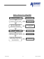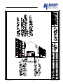
1
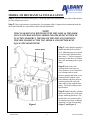
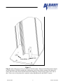
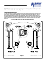
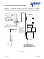
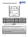
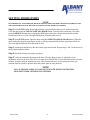
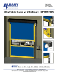
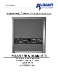
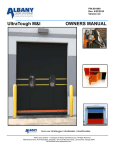
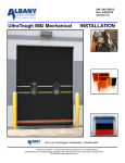
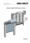
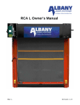
PART NUMBER 350016-0000 RAPID-ROLL DOOR OWNER‟S MANUAL MODEL 355 975-A OLD NORCROSS ROAD LAWRENCEVILLE, GA 30045 (770) 338-5000 TEL (770) 338-5034 FAX (877) 925-2468 TOLL FREE WARNING DO NOT INSTALL, OPERATE, OR SERVICE THIS PRODUCT UNLESS YOU HAVE READ AND UNDERSTAND THE SAFETY PRACTICES, WARNINGS, INSTALLATION, AND MAINTENANCE INSTRUCTIONS CONTAINED IN THIS MANUAL. 355 Architectural Specifications 350016-0000 4 Version 4/23/2010 STATEMENT OF WARRANTY UltraFabric, RapidRoll 230, RapidRoll 355, RapidRoll 670 High Speed Doors ONE-YEAR WARRANTY ON MECHANICAL AND ELECTRICAL COMPONENTS Albany Door Systems warrants to the original owner of the door that the mechanical and electrical components will be free from defects in material and workmanship for a period of one (1) year from the date of shipment. Vinyl fabric material, mesh screen material and transparent (PVC) polyvinyl chloride material is warranted for one (1) year. Two (2) ply panel material is warranted for two (2) years and three (3) ply panel material is warranted for three (3) years. Only defects brought to the attention of Albany Door Systems during the warranty period will be covered by this warranty. Albany Door Systems will replace component parts covered by this warranty, which are found to be defective upon inspection by an Albany Door Systems representative. Installation or use of parts other than those authorized by Albany Door Systems will void this warranty. PARTS AND ASSEMBLIES sold separately by Albany Door Systems that fail due to defects in material or workmanship within ninety (90) days from the date of shipment will be replaced under warranty provided installation has been carried out in accordance with all Albany Door Systems procedures. This warranty is limited to providing a replacement part only. This warranty does not cover freight, special charges, or any costs associated with the installation of the replacement part. This warranty covers material failure under normal wear conditions; it does not cover damage caused by collision or other abuse of the product. Adjustments made to the control panel or to the mechanical operation of the door without the authorization of Albany Door Systems will void this warranty. Any changes made to product configuration without the express written approval from Albany Door Systems may null and void this warranty. Albany Door Systems’ obligations under this warranty are limited to repairing or replacing the defective part including labor and Albany Door Systems shall not be responsible for any other losses or damages due to the operation of any door or parts covered by this warranty. Warranty parts will be shipped regular ground freight at the expense of Albany Door Systems. This warranty shall be void in its entirety if the failure of any product shall be caused by any installation, operation, or maintenance of the product which does not conform with the requirements set forth by the seller in the applicable product manuals or is in the result of any cause other than a defect in the material or workmanship of the product. No other oral or written representations made by Albany Door Systems or its agents are a part of this warranty unless specifically set forth in writing by an authorized Albany Door Systems official. THE ABOVE SET FORTH WARRANTY IS SELLER'S SOLE WARRANTY. SELLER MAKES NO OTHER WARRANTY OF ANY KIND WHATSOEVER, EXPRESSED OR IMPLIED; AND ALL IMPLIED WARRANTIES OF MERCHANTABILITY AND FITNESS FOR A PARTICULAR PURPOSE WHICH EXCEED THE AFORESTATED OBLIGATION ARE HEREBY DISCLAIMED BY SELLER AND EXCLUDED FROM THIS AGREEMENT. Albany Door Systems - A Company of Albany International Corp. All Rights Reserved 1080 Maritime Drive, Port Washington, WI 53074 - 975-A Old Norcross Road, Lawrenceville, Georgia 30045 262-268-9885 or 877-925-2468 v4202010 350016-0000 5 Version 4/23/2010 SAFETY PRACTICES WARNING THOROUGHLY READ THESE SAFETY PRACTICES PRIOR TO INSTALLING, OPERATING, OR SERVICING A HIGH-SPEED, RAPID-ROLL™ DOOR. FAILURE TO FOLLOW THESE SAFETY PRACTICES MAY RESULT IN PROPERTY DAMAGE, PERSONNEL BODILY INJURY, OR DEATH. 1. Do not operate a RAPID-ROLL™ Door while you are under the influence of drugs or alcohol. 2. Do not use the door if any parts appear to be broken or damaged. 3. Stay clear of the door while it is operating. 4. Keep hands and feet clear of the door at all times. 5. Do not drive through the door opening unless door is completely open. 6. Maintain a clear door opening at all times. Keep the door opening free of any obstructions. 7. Remove power at the fused disconnect during all electrical or mechanical service. OSHA requires a disconnect to be properly tagged and locked out during all maintenance or service of equipment. 8. All electrical troubleshooting or service must be performed by a qualified electrician or service person and must meet all applicable local, state, federal, international, and other governing agency codes. 9. USE EXTREME CAUTION when it is necessary to service the control panel while it is energized. 10. If you have any questions, please contact your local Albany service provider for assistance. Otherwise contact Albany Door Systems at 1-877-925-2468 for information on your local distributor. 350016-0000 6 Version 4/23/2010 PACKING LIST Before beginning the installation, thoroughly inspect the crate to ensure all necessary components are there. The following list applies to a standard Model 355 door (No optional parts are included unless ordered that way). Left Hand and Right Hand Side Columns with attached Covers (1 set) Top Roll Assembly (1) Drive Unit w/torque arrestor bracket (1) Electrical Control Panel (1) Safety Photocells (1 set)1 Bottom Rail Profile (1) Counterbalance Springs (2) Tensioning Ropes (2) Width Gauge Assembly Hardware OPTIONAL PARTS Motion Detector Floor Loop Transmitters Auxiliary Pushbuttons Stations Pull Cords SUGGESTED TOOLS REQUIRED 5mm allen wrench 6mm allen wrench 8mm allen wrench 18mm open end wrench Screwdriver Tape Measure Come-a-along 350016-0000 Water Level Carpenters Level Hammer Wrench set (SAE) Screwdriver Set Wrench set (METRIC) Drill bits 7 Version 4/22/2010 MODEL 355 MECHANICAL INSTALLATION Step 1 Unpack crate and inventory parts, comparing against the packing list in the front of this manual, to verify all parts are on site. Step 2 Using a tape measure, determine the clear opening width. Compare this measurement with the door ordered width. See crate label for door ordered dimensions. NOTE THE CLEAR OPENING WIDTH MUST BE THE SAME AS THE DOOR MANUFACTURED WIDTH IN ORDER FOR THE RESET SYSTEM TO FUNCTION PROPERLY. THIS MEANS THE DISTANCE BETWEEN THE SIDE FRAMES AT THE TOP, MIDDLE AND BOTTOM MUST EQUAL THE DOOR WIDTH. Step 3 Verify that the opening is plumb and that the floor slab is level. Shimming may be required to level the side columns but no more then ½”. Refer to approval drawings for this door to confirm drive side mounting (left or righthand). Slotted Holes Step 4 Remove the side columns from crate (one at a time). Remove covers from both side columns and set aside. Remove springs and inner covers from both side columns. Erect both columns and place them in position against the wall with inner edges in line with the door jambs. Verify the width per door specification. Step 5 Plumb both side columns and secure them to the wall using proper anchoring hardware. The anchor holes are slotted to allow for adjustment of door width and centering over the door opening. (Figure 1 and Figure 2) Figure 1 350016-0000 8 Version 4/22/2010 Slotted Holes Figure 2 Step 6 Attach width gauge to the rear of door at both head plates. Removal of the black plastic funnels on the head plates will make installing the width gauge easier along with the routing of the photocell cables. Run wires under the back funnel and inside width gauge, from non-drive side to drive side of door. These wires are for photocells, contactless safety edge photocells, and SRD2™ sensors. 350016-0000 9 Version 4/22/2010 Step 7 Using an approved lifting device, place a lifting strap around the top roll assembly, lift and remove from shipping crate. Raise the top roll assembly into position and lower it slowly onto the top of both side columns. Ensure the bearing housings are located outside the head plates. Secure the top roll at both head plates on each side of door. (Figure 3) Figure 3 Step 8 Slide the drive unit onto the drive side stub axle. Attach torque arrestor bracket to the head plate. Step 9 Remove straps holding door fabric in place. Disengage the drive unit brake by pulling down on the brake release lever and rotate the top roll until the bottom edge of the fabric is approximately 30 mm (1.25 in) below the head plates. 350016-0000 10 Version 4/22/2010 Step 10 Attach and place 2 pre-wraps of tensioning rope on both rope pulleys and allow rope to drape down over the front of the side columns. (Figure 4) Special instructions for rope The white rope does not so readily fit into the groove of the take up spool and requires a special step to allow for this. You must pull the single inner core of the rope out about 4 inches and cut it. This will help in reducing the diameter of the rope at the leading end. Then use a lighter to heat the end of the rope and roll it between your fingers to slightly shrink the end of the rope. This will give the rope some rigidity so that you can now thread it into the take up spool. Be careful not to burn your figures when doing this DO NOT DRILL HOLE IN TAKE UP DRUM FOR ROPE. Top Roll – 2 Prewraps Knot FRONT OF DOOR FRONT OF DOOR Figure 4 350016-0000 11 Version 4/22/2010 Step 11 Slide the bottom rail profile into the base of the curtain and center. Once the bottom beam is centered, then locate the 2 predrilled holes on each end of profile, drill through the fabric and use the provided slotted screws and acorn nut to secure the bottom beam in place. Step 12 Run the tensioning rope through the appropriate pulleys in the counterbalance system corresponding to the drawing placed inside the side columns. Ensure the rope is run through the sliding part of the CSE block. (Figure 4) Run the rope through the hole in the aluminum bracket on bottom profile. While running the rope for the door try to ensure that there are no twists or kinks in the rope. DO NOT CUT EXCESS ROPE UNTIL STEP 15 HAS BEEN DONE. Step 13 Re-install both inner side column covers. Re-install counterbalance springs inside side columns. Take note, the springs must be attached so that the spring is sitting against the short section of brush that is on the inner cover. This brush dampens the movement of the spring allowing for a quiet function. The spring will be noisy if this step is not performed correctly. Step 14 Using a come-a-long or similar pulling device, stretch the springs to the horizontal arrows marked on the diagrams located on the side column covers. Remove slack from the tensioning rope and secure rope in place by tying a knot in it. (Figure 4) Step 15 When the counter balance system has been fully installed, disengage the drive unit brake and manually move door over its entire range of motion. Ensure that the fabric and wind clips go behind the inner cover. NOTE: The door must be cycled 20-30 times to allow for the rope to stretch. This will require you to make additional adjustments to the spring tension. Once the stretching has settled, you can then put the door into operation. Be very sure that this is done before cutting the excess rope. Step 16 is detailed in the following two pages Step 16 Run cable for bowden lever (emergency disengagement lever pre-mounted on drive side, side column cover) through pre-drilled hole in the head plate. Pull enough slack thru so that you can now slide the 2’ section of the cable sheath on. Run cable down through the brake release lever on the side of the motor. Loop the cable thru the grid on the bottom of the motor fan cover and use the barrel clamp supplied to fix the cable to the fan cover. Do not extra cable until final adjustments are made. (Figure 6) Additional adjusting may be required once the side frame cover is installed so that the brake release works properly. Attach the other end of cable (with spring) to the bowden lever while installing drive side cover profile at the same time. Secure the cover profile at the top and bottom using supplied bolts. (Figure 7) Check and ensure that when you pull on the disengagement handle the door releases and can be pulled up or down. Step 17 Install the remaining cover profile on the other side of the door using supplied bolts. Step 18 Attach barrel cover to both head plate mounting brackets using supplied screws and washers. Place the side column covers over the head plates and attach using supplied screws. 350016-0000 12 Version 4/22/2010 Figure 7 Figure 6 350016-0000 13 Version 4/22/2010 INSTALLATION OF MANUAL DISENGAGEMENT LEVER TOP ROLL BEARING BRACKET (TOP VIEW) DRIVE UNIT 1. RUN BARE CABLE UP THROUGH SIDE FRAME AND SMALL HOLE IN BEARING PLATE. CABLE SHEATH STARTS HERE. RUN CABLE FROM TOP OF BEARING PLATE OVER TO DRIVE UNIT. SECURE BARE CABLE TO BOTTOM OF MOTOR COVER USING SUPPLIED CABLE CLAMP. ALSO REFER TO FIGURE 6 Figure 9 350016-0000 14 Version 4/22/2010 THRU-WALL DISENGAGEMENT LEVER INSTALLATION Figure 10 350016-0000 15 Version 4/22/2010 ELECTRICAL INSTALLATION The following instructions are recommended guidelines for electrically installing a typical Model 355 door. Actual wiring may be different based on what options, special instructions, special components, etc. were ordered with the door. Consult the electrical schematics that are supplied with the door. These should be located inside the control panel. WARNING CONTROL PANEL CONTAINS HIGH VOLTAGE. THE FOLLOWING PROCEDURES SHOULD BE PERFORMED BY QUALIFIED ELECTRICAL PERSONNEL ONLY. WIRING MUST MEET ALL LOCAL, STATE, FEDERAL, INTERNATIONAL, OR OTHER GOVERNMENT AGENCY CODES. FAILURE TO DO COULD RESULT IN SERIOUS INJURY OR DEATH. NOTE TO AID THE WIRING AND SERVICE OF ALL ELECTRICAL CIRCUITS, TAG OR LABEL ALL WIRE ENDS DURING THE FOLLOWING ELECTRICAL INSTALLATION. ALSO, ALL THREE PHASE POWER WIRES SHOULD BE RUN IN SEPARATE CONDUIT FROM ALL OTHER CONTROL CIRCUIT WIRING (I.E. PULSE ENOCDER WIRING). 1. Mount the control panel at a height of approximately four feet from the floor on the drive side of the door. 2. Run electrical conduit and wires for: pulse encoder cable, drive unit power leads, and receptacle cable. Plug all wires into the electrical receptacles located above the drive unit (Figure 11). 3. Install all the actuators and wire according to the electrical schematics supplied with the door. 4. Install a fused disconnect beside the control panel. The main supply to the All Star drive system can be from 208 VAC up to 600 VAC. The control panel is fused at 15 amps. CAUTION VERIFY ALL FIELD WIRING TO ENSURE TERMINAL CONNECTIONS ARE TIGHT AND CORRECT. A FUSED DISCONNECT IS REQUIRED FOR EACH ALBANY DOOR AS A MEANS OF DISCONNECTING INCOMING POWER FROM THE CONTROL PANEL.THIS DISCONNECT IS NORMALLY SUPPLIED BY OTHERS. 350016-0000 16 Version 4/22/2010 FIGURE 11 Label What Plug Location X31 X33 X35 X36 X37.1 X38.1 THERMAL SWITCH TOP OPEN PROX. PHOTOCELL RECEIVER PHOTOCELL TRANSMITTER CSE RECIEVER CSE TRANSMITTER 3 WIRE 3 WIRE 3 WIRE 3 WIRE 4 WIRE 4 WIRE BLK. WIRE MOTOR BLK. WIRE SIDE FRAME LEFT SIDE FRAME RIGHT SIDE FRAME RIGHT SIDE FRAME LEFT SIDE FRAME WARNING BEFORE APPLYING POWER TO CONTROL PANEL, CHECK LINE VOLTAGE AT DISCONNECT WITH A VOLTMETER. The plug-in-play box shown on this page was eliminated from current production doors so that all the items listed above are field wired to the control panel. Refer to the schematics supplied with the control panel for wiring designations. 350016-0000 17 Version 4/22/2010 ELECTRICAL START UP Step 1 Manually bring the door to the halfway closed position. This can be done by pulling down on the brake release lever to release the drive unit brake and moving the curtain by hand (Figure 12). Step 2 Check for correct line voltage at the disconnect with a voltmeter. Utilize the All-Star control panel manual to make all field wire connections to the panel. Apply power to the control panel. Ensure the POWER LED’s on both the PLC and frequency inverter are lit. Also ensure that the RUN LED is lit on the PLC. Step 3 Push the SETUP button. The RESET light on the outside of the panel will come on and relay CR-11 will be energized at this point. Using the OPEN/CLOSE JOG DOOR button located on the control panel backplate (small rocker switch), jog the door in the close direction. If the door closes, go to the next step. If the door opens, then the phase rotation on the drive unit is backwards. Swap two of the three motor leads in the panel to change the motor rotation (terminals T11, T12, T13). Disengaged FIGURE 12 350016-0000 18 Version 4/22/2010 SETTING DOOR LIMITS NOTE IT IS IMPORTANT TO ENSURE THE DOOR IS MOVING WHEN THE RESET BUTTON IS PUSHED TO SET THE CLOSE LIMIT. DO NOT RELEASE JOG SWITCH UNTIL DOOR HAS STOPPED. Step 1 Press SETUP button. Reset light will turn on; this indicates that you are in the setup mode. Close the door using the OPEN/CLOSE JOG DOOR button. Once the door reaches the close limit, press the RESET button before releasing the JOG button, the door will stop automatically and the closed limit will be set. The reset light should turn off at this point as well. Step 2 Press SETUP button. Open the door using the OPEN/CLOSE JOG DOOR button. When the door reaches the open limit proximity switch, it will stop automatically and the open limit will be set. The reset light should turn off at this point as well. Step 3 Actuate door and observe the door limits (open and closed). Repeat steps 1 and 2 as necessary to finely adjust both door limits. Step 4 Check all actuators for proper operation. Step 5 Verify the automatic operation of the door. The time delay to close is adjustable via an adjustment screw on the face of the PLC (see drawing # NONAUTO). If non-automatic mode is desired for door operation, turn the adjustment screw fully counterclockwise. In non-automatic mode, the actuator must be pulsed to open the door and pulsed again to close the door. NOTE NON-AUTOMATIC MODE CANNOT BE USED WITH MOTION DETECTORS, LOOP DETECTORS, OR PRESENCE SENSORS. 350016-0000 19 Version 4/22/2010 Quick reference for setting limits Reset Light turns on Press SETUP button Close door with „JOG‟ switch Door starts to CLOSE When door reaches bottom limit, press RESET button while the door is still moving. 350016-0000 Door in the CLOSED POSITION Press SETUP button Reset Light turns on OPEN door with „JOG‟ switch Door starts to OPEN When door reaches the open limit proximity switch, it will stop automatically Door STOPS Moving 20 Version 4/22/2010 350016-0000 21 Version 4/22/2010 MAINTENANCE WARNING REMOVE ALL POWER AT THE FUSED DISCONNECT DURING ALL ELECTRICAL OR MECHANICAL SERVICING. DISCONNECT MUST BE PROPERLY LOCKED OUT DURING MAINTENANCE OR SERVICE OF EQUIPMENT. DAILY INSPECTION 1. Run through a full door cycle (open/close) and ensure smooth operation. Verify that the door is not jammed or hanging up. 2. Check the door fabric for any visible damage or unusual wear. 3. Check all actuators for proper operation. If applicable, verify the automatic operation of the door. 4. Check the operation of safety photocells and bottom rail reset system. QUARTERLY INSPECTION 1. Inspect all hardware for proper tightness. Any loose hardware should be tightened. It is recommended to apply a tread locker compound to any bolts that are coming loose. i.e. Loctite 242 (blue). 2. Observe both open and close door limits. Ensure a proper floor seal is intact when the door is fully closed. There should be no visible light seen between bottom rail rubber seal and floor. If limits are out of adjustment, re-adjust according to the procedure outlined in the electrical startup section of this manual. 3. Inspect cables and pulleys for unusual wear. Ensure that either tensioning rope is not slack, misaligned, or fraying. Replace worn or damaged components as necessary. 350016-0000 22 Version 4/22/2010 SRD2™ RESET SYSTEM The Model 355 door comes standard with the SRD2™ self-repair device. The tensioning rope remains attached to the bottom rail profile allowing it to swing away if struck. The tension on the rope will automatically pull the bottom rail back into place. The Contactless Safety Edge™ does need to be reset, however. To accomplish this, perform the following procedure: 1. Ensure the door opening is completely clear of any obstructions. 2. Push and hold the blue SRD2 button on the face of the control panel. The door will automatically close and re-latch the bottom rail with the Contactless Safety Edge™ photocells. The door will also stop automatically when the bottom limit is reached. 3. Resume normal door operation. 4. Figure 13 shows an improperly latched bottom beam, and Figure 14 shows a properly latched bottom beam. Figure 14 Figure 13 350016-0000 23 Version 4/22/2010 MODEL 355 TROUBLESHOOTING GUIDE WARNING ENSURE THAT THE POWER LED ON THE FREQUENCY INVERTER IS FULLY EXTINGUISED WHENEVER DE-ENERGIZING CONTROL PANEL TO PERFORM ANY ELECTRICAL WORK (WAIT AT LEAST 30 SECONDS). THIS WILL INDICATE THAT THE HIGH VOLTAGE CAPACITORS HAVE BEEN FULLY DRAINED. FAILURE TO WAIT MAY RESULT IN ELECTRICAL SHOCK. The POWER and RUN green LED’s on the PLC must be on. If not, check for 120V power to terminals L&N. If no power is present, de-energize control panel and check main disconnect and all control panel fuses. The POWER LED on the frequency inverter must also be on. At least one input LED on the PLC should be on. If not, ensure the EMERGENCY STOP button is pulled out. If no inputs turn on, check for missing jumpers and/or switch wiring in series with the EMERGENCY STOP button; see drawing #AF35. Whenever power has been removed to the control panel, the door will go through a setup routine to reset the door limits. It will open at jog speed until the home proximity switch (open limit) has been reached. It will then time out and continue to operate at normal speed. PLC INPUTS2 (X0-X7) INPUTS (“IN” LED‟S) 0 1 2 3 4 5 6 7 DESCRIPTION Pulse encoder channel B – a counting signal utilized by the PLC to keep track of door position. Can be either on or off. Pulse encoder channel A – a counting signal utilized by the PLC to keep track of door position. Can be either on or off. SETUP button and top overrun proximity switch input – will place door in “setup” mode, reset button light will come on. (N/C)3 Jumper wire – will be on continuously. (N/C) Actuator input – will come on for as long as the actuator has been activated. If on continuously, check actuators.(N/O) Safety Devices. Photocells and Contactless Safety Edge™ are wired in series with this input. Should be on continuously unless a safety device is activated. (N/C) SRD2™ proximity switch input – will be on as long as the bottom rail is latched with the CSE. Removing input will place PLC in “setup” mode and the RESET button will be lit. (N/C) Reset input – will come on when the RESET button is pushed. Activating this input will clear the “setup” mode (reset light is on). If mode does not clear, check alarm light on frequency inverter. (N/O) 2 Reference drawing #AF35 when using this chart. 3 N/C – devices connected to this input are wired as normally closed; N/O – devices connected to this input are wired as normally open. 350016-0000 24 Version 4/22/2010 Notes: if the ALARM LED on the frequency inverter is on, call the factory for direction. To clear alarm condition, remove power to control panel. The most common cause of an inverter alarm is a motor current overload condition. Ensure that the door is not jammed in any way and will move freely over the entire range of motion when the motor brake is manually released. 350016-0000 25 Version 4/22/2010 RAPID ROLL® MODEL 355 INSTALLATION CHECKLIST Door Serial No. __________ Date of Installation __________ Installer’s Name _________________________ Enduser__________________________ Company _______________________________ ________________________________ City ___________________ State ________ City _________ State ____ Zip_______ Phone No. ______________ MECHANICAL: Crate fully unpacked. Verified door parts against packing list. No parts are missing and they are undamaged. Drive unit assembled to top roll assembly. Door top roll assembly attached to side frames. Side frames are plumb and door top roll assembly is level. Door secured to wall along side frames. Counter balance spring properly tensioned. Door does not bind in any position and has free movement over the entire range of motion. Photocells mounted on inside back profiles. (Factory Wired) ELECTRICAL: Fused disconnect installed and properly wired to control panel. Three phase power available at control panel. Control panel mounted at a serviceable height. Drive unit, door limit switches, gearbox disconnect switch, and brake motor kill switch properly wired to control panel. Door actuators installed and properly wired to control panel (i.e. pushbuttons, pull switches, floor loops, etc.). Proper phase rotation verified. Door limits properly set. Gearbox breather plug installed. All actuators tested and function properly. Door has been cycled at least 10 times to verify proper operation. Notes:___________________________________________________________ ________________________________________________________________ ________________________________________________________________ ________________________________________________________________ FAX COMPLETED FORM TO ALBANY INTERNATIONAL SERVICE DEPARTMENT AT (770) 338-5034. 350016-0000 26 Version 4/22/2010