1
Installing a Dialogic® TX 4000
PCI SS7 Network Interface
Board
September 2010
64-0430-04 Rev A
www.dialogic.com
Installing a Dialogic® TX 4000 PCI SS7 Network Interface Board
Copyright and legal notices
Copyright © 2007-2010 Dialogic Corporation. All Rights Reserved. You may not reproduce this document
in whole or in part without permission in writing from Dialogic Corporation at the address provided below.
All contents of this document are furnished for informational use only and are subject to change without
notice and do not represent a commitment on the part of Dialogic Corporation or its subsidiaries
(“Dialogic”). Reasonable effort is made to ensure the accuracy of the information contained in the
document. However, Dialogic does not warrant the accuracy of this information and cannot accept
responsibility for errors, inaccuracies or omissions that may be contained in this document.
INFORMATION IN THIS DOCUMENT IS PROVIDED IN CONNECTION WITH DIALOGIC® PRODUCTS. NO
LICENSE, EXPRESS OR IMPLIED, BY ESTOPPEL OR OTHERWISE, TO ANY INTELLECTUAL PROPERTY
RIGHTS IS GRANTED BY THIS DOCUMENT. EXCEPT AS PROVIDED IN A SIGNED AGREEMENT BETWEEN
YOU AND DIALOGIC, DIALOGIC ASSUMES NO LIABILITY WHATSOEVER, AND DIALOGIC DISCLAIMS ANY
EXPRESS OR IMPLIED WARRANTY, RELATING TO SALE AND/OR USE OF DIALOGIC PRODUCTS INCLUDING
LIABILITY OR WARRANTIES RELATING TO FITNESS FOR A PARTICULAR PURPOSE, MERCHANTABILITY, OR
INFRINGEMENT OF ANY INTELLECTUAL PROPERTY RIGHT OF A THIRD PARTY.
Dialogic products are not intended for use in medical, life saving, life sustaining, critical control or safety
systems, or in nuclear facility applications.
Due to differing national regulations and approval requirements, certain Dialogic products may be suitable
for use only in specific countries, and thus may not function properly in other countries. You are
responsible for ensuring that your use of such products occurs only in the countries where such use is
suitable. For information on specific products, contact Dialogic Corporation at the address indicated below
or on the web at www.dialogic.com.
It is possible that the use or implementation of any one of the concepts, applications, or ideas described in
this document, in marketing collateral produced by or on web pages maintained by Dialogic may infringe
one or more patents or other intellectual property rights owned by third parties. Dialogic does not provide
any intellectual property licenses with the sale of Dialogic products other than a license to use such
product in accordance with intellectual property owned or validly licensed by Dialogic and no such licenses
are provided except pursuant to a signed agreement with Dialogic. More detailed information about such
intellectual property is available from Dialogic’s legal department at 9800 Cavendish Blvd., 5th Floor,
Montreal, Quebec, Canada H4M 2V9. Dialogic encourages all users of its products to procure all necessary
intellectual property licenses required to implement any concepts or applications and does not condone or
encourage any intellectual property infringement and disclaims any responsibility related thereto. These
intellectual property licenses may differ from country to country and it is the responsibility of those who
develop the concepts or applications to be aware of and comply with different national license
requirements.
Any use case(s) shown and/or described herein represent one or more examples of the various ways,
scenarios or environments in which Dialogic® products can be used. Such use case(s) are non-limiting
and do not represent recommendations of Dialogic as to whether or how to use Dialogic products.
Dialogic, Dialogic Pro, Brooktrout, Diva, Cantata, SnowShore, Eicon, Eicon Networks, NMS
Communications, NMS (stylized), Eiconcard, SIPcontrol, Diva ISDN, TruFax, Exnet, EXS, SwitchKit, N20,
Making Innovation Thrive, Connecting to Growth, Video is the New Voice, Fusion, Vision, PacketMedia,
NaturalAccess, NaturalCallControl, NaturalConference, NaturalFax and Shiva, among others as well as
related logos, are either registered trademarks or trademarks of Dialogic Corporation or its subsidiaries.
Dialogic's trademarks may be used publicly only with permission from Dialogic. Such permission may only
be granted by Dialogic’s legal department at 9800 Cavendish Blvd., 5th Floor, Montreal, Quebec, Canada
H4M 2V9. Any authorized use of Dialogic's trademarks will be subject to full respect of the trademark
guidelines published by Dialogic from time to time and any use of Dialogic’s trademarks requires proper
acknowledgement.
The names of actual companies and product mentioned herein are the trademarks of their respective
owners.
This document discusses one or more open source products, systems and/or releases. Dialogic is not
responsible for your decision to use open source in connection with Dialogic products (including without
limitation those referred to herein), nor is Dialogic responsible for any present or future effects such usage
might have, including without limitation effects on your products, your business, or your intellectual
property rights.
2
Dialogic Corporation
Installing a Dialogic® TX 4000 PCI SS7 Network Interface Board
Revision history
Revision
Release date
Notes
9000-62363-10
September 2003
SRR, SS7 4.0 Beta
9000-62363-11
May 2004
SRR, SS7 4.0
9000-62363-12
August 2004
SRR, SS7 4.1
9000-62363-13
April 2005
LBG
9000-62363-14
July 2008
LBG, SS7 5.0
64-0430-01
July 2009
LBG, SS7 5.1
64-0430-02
May 2010
LBG
64-0430-03
July 2010
LBG
64-0430-04 Rev A
September 2010
LBG
Last modified: September 9, 2010
Refer to www.dialogic.com for product updates and for information about support policies, warranty
information, and service offerings.
Dialogic Corporation
3
Installing a Dialogic® TX 4000 PCI SS7 Network Interface Board
Table of Contents
Table of Contents ....................................................................................................... 4
Introduction .............................................................................................................. 5
Configuring the hardware ............................................................................................ 6
Installing the board .................................................................................................... 8
Assigning a CP number ............................................................................................... 9
Establishing network connections ............................................................................... 10
Connecting TX boards for redundancy ......................................................................... 13
Interface status LEDs................................................................................................ 16
Board status LEDs .................................................................................................... 17
Compliance statements ............................................................................................. 18
Europe .................................................................................................................... 19
Australia ................................................................................................................. 22
South Korea ............................................................................................................ 23
China ..................................................................................................................... 24
Product declarations and global approvals ................................................................... 26
RoHS Statement ...................................................................................................... 26
Product environmental information ............................................................................. 26
Limited warranty ...................................................................................................... 26
4
Dialogic Corporation
Installing a Dialogic® TX 4000 PCI SS7 Network Interface Board
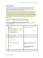
Introduction
The Dialogic® TX 4000 PCI SS7 Network Interface Board provides four T1 or E1
digital trunk interfaces and two Ethernet 10/100Base-T interfaces. For more
information, refer to the Dialogic® TX 4000 PCI SS7 Network Interface Board
Installation Manual available on www.dialogic.com.
Note: The product(s) to which this document pertains is/are among those sold by
NMS Communications Corporation (“NMS”) to Dialogic Corporation (“Dialogic”) in
December 2008. Certain terminology relating to the product(s) has been changed,
whereas other terminology has been retained for consistency and ease of reference.
For the changed terminology relating to the product(s), below is a table indicating
the “New Terminology” and the “Former Terminology”. The respective terminologies
can be equated to each other to the extent that either/both appear within this
document.
Former terminology
Current terminology
NMS SS7
Dialogic® NaturalAccess™ Signaling Software
Natural Access
Dialogic® NaturalAccess™ Software
The following table summarizes the steps for installing the TX 4000 hardware and
software components:
Step
Description
For details, refer to...
1
Ensure that your system meets the system
requirements.
Dialogic® TX 4000 PCI SS7 Network
Interface Board Installation Manual
Note: The TX 4000 board requires a high current
from the 3.3 V power supply.
The board has the following power requirements:
•
•
•
6.5 A maximum @ 3.3 V
0.5 A maximum @ 5.0 V
0.1 A maximum @ 12.0 V
2
Power down the system if it is running.
3
Configure the TX 4000 board to enable H.100 bus
termination, if applicable.
Configuring the hardware on page 6
4
Configure the TX 4000 board to enable monitor
mode, if applicable.
Configuring the hardware on page 6
5
Install the TX 4000 board into one of the
computer's PCI bus slots.
Installing the board on page 8
6
Power up the system.
7
Install the NaturalAccess software.
The Natural Access Installation booklet and
Natural Access Developer's Reference
Manual
8
Install the Dialogic® NaturalAccess™ Signaling
Software.
The Installing Dialogic® NaturalAccess™
Signaling Software and Dialogic®
NaturalAccess™ Signaling Software
Configuration Manual
9
Assign a CP number for each TX 4000 board.
Assigning a CP number on page 9
10
Connect the board interfaces to T1 or E1 trunks.
Establishing network connections on page 10
Dialogic Corporation
5
Installing a Dialogic® TX 4000 PCI SS7 Network Interface Board
Step
Description
For details, refer to...
11
If applicable, connect the Ethernet interfaces for
board redundancy, to a SIGTRAN network, or
both.
Connecting TX boards for redundancy on
page 13
12
Verify that the TX 4000 board is operational.
Interface status LEDs on page 16
Board status LEDs on page 17
Configuring the hardware
Before installing the TX 4000 board, use the following procedures to configure H.100
bus termination and monitor mode if applicable.
Caution:
The TX 4000 board is shipped in a protective anti-static container. Leave the board in its
container until you are ready to install it. Handle the board carefully and hold it only by its
edges. We recommend that you wear an anti-static wrist strap connected to a good earth
ground whenever you handle the board. Take care not to touch the gold fingers that plug
into the PCI bus connectors.
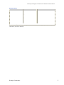
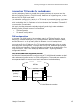
Configuring H.100 bus termination
The TX 4000 board connects to an H.100 bus. Boards on the H.100 bus are
connected to one another with an H.100 bus cable. Enable bus termination on the
board located on each end of the H.100 bus:
H.100 bus cable
Enable bus
termination
Enable bus
termination
DIP switch S2 on the TX 4000 board controls the H.100 bus termination. By default,
all S2 switches are set to the OFF position. H.100 bus termination is disabled. To
enable H.100 bus termination, set all S2 switches to the ON position only for the
boards that are on the ends of the H.100 bus.
6
Dialogic Corporation
Installing a Dialogic® TX 4000 PCI SS7 Network Interface Board
ON
1 2 3 4 56 7 8
OFF
S2
ON
1234
S3
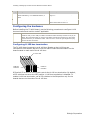
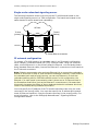
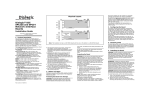
The following illustration shows the default settings for the TX 4000 DIP switches
(H.100 bus termination and SS7 Monitor mode disabled):
OFF
Configuring SS7 Monitor mode
DIP switch S3 controls the SS7 Monitor mode. By default, all S3 switches are set to
the ON position. This setting disables Monitor mode. When Monitor mode is disabled,
the TX board is an active participant in the network.
To enable Monitor mode, set all S3 switches to the OFF position. In this mode, the
board becomes a passive listening device that monitors network traffic.
DIP switch S1
DIP switch S1 controls the operation of the board. By default, only switch 2
(AUTOSTART) is set to the ON position; all other S1 switches are set to the OFF
position. Switch 5 is reserved for future use. Do not modify the default settings for
this switch.
Set switch 8 (SW MIN BOOT) to ON to boot the board to the original software image
instead of using the current production software image. This allows for recovery from
any condition that resulted in the corruption of the production software image. After
setting this switch to ON, use txreset to boot the backup software image, and then
use txflash to burn a clean copy of the production image. Once the production image
is completely transferred to the board's flash memory, turn this switch to OFF, and
issue txreset to boot the board using the newly loaded production software image.
Dialogic Corporation
7
Installing a Dialogic® TX 4000 PCI SS7 Network Interface Board
Installing the board
Complete the following steps to install the TX 4000 board:
1. If necessary, configure the board as described in Configuring the hardware on
page 6.
2. Power down the computer and disconnect the power cord from the power
source. Remove the cover from the computer and set it aside.
3. If you are placing the board into a PCI chassis, remove the PCI retainer
bracket by unscrewing it from the board. The bracket is not needed for the
board to properly fit into the chassis.
If you are placing the board into an ISA chassis, leave the PCI retainer
bracket attached to the board. The bracket is needed for the board to fit
properly into the chassis.
4. Remove the blank slot cover from an open PCI bus slot.
5. Arrange the TX 4000 board and other H.100 boards in adjacent PCI bus slots.
Insert the TX 4000 board firmly into the slot. Ensure that the gold-striped
edge of the board is seated properly in the expansion slot groove and the
bracket of the board is seated in the groove that previously held the slot
cover.
6. Align the top of the board bracket with the hole on the top of the expansion
slot, and replace the screw that previously held the blank slot cover.
7. Connect the H.100 bus cable to the TX 4000 board.
If you have multiple H.100 boards, connect the H.100 bus cable to each
H.100 board.
Verify that the S2 DIP switches are set for H.100 bus termination if the TX
4000 board is installed at either end of the H.100 cable.
8. Replace the cover and connect the computer to the power source.
8
Dialogic Corporation
Installing a Dialogic® TX 4000 PCI SS7 Network Interface Board
Assigning a CP number
Use the txcpcfg utility to assign a CP number. Depending on the operating system
environment, the txcpcfg utility is located in the following directory:
•
Windows: Program Files\Dialogic\tx\bin\
•
UNIX: /opt/dialogic/tx/bin/
Complete the following steps to assign a CP number:
1. Power up the system if it is not running.
In a Windows system, the Windows® New Hardware Wizard appears and
prompts you for the files required to activate the SS7 drivers. Refer to the
Installing Dialogic® NaturalAccess™ Signaling Software for detailed
information.
2. At the prompt, invoke txcpcfg by entering the following command:
txcpcfg
txcpcfg displays the bus number, slot number, CP number, and CP model of
boards that are present and configured. Only the bus number, slot number,
and CP model identify the board that you are currently configuring. The CP
number is undefined.
3. Record the bus and slot values for the undefined TX 4000 board.
4. Assign a unique CP number to each undefined board by entering the following
command
txcpcfg
bus slot unique_CP_number
where
•
bus is the bus number of the TX 4000 board that you are configuring.
•
slot is the slot number of the TX 4000 board that you are configuring.
•
unique_CP_number is a number you assign. Valid CP numbers within
the system start at 1 and must be unique. They do not have to be
consecutive.
5. Verify the configuration of all of the TX boards by entering the following
command:
txcpcfg
6. Save the configuration changes.
In a Windows system, configuration changes are saved automatically. In a
UNIX system, configuration changes are deleted when you restart the system.
Save the changes by editing the cpcfg file as described in the Dialogic® TX
4000 PCI SS7 Network Interface Board Installation Manual.
Dialogic Corporation
9
Installing a Dialogic® TX 4000 PCI SS7 Network Interface Board
Establishing network connections
Before connecting the board to a network, refer to
www.dialogic.com/declarations/default.htm for information on the current approvals.
The trunk connectors and the Ethernet connectors are located on the PCI end
bracket as shown in Interface status LEDs on page 16.
Warning:
Important safety notes for telephony connections:
•
Allow only qualified technical personnel to install this board and the associated
telephone wiring.
•
Make sure the PC chassis is grounded through the power cord or by other means
before connecting the telephone line.
•
If your system requires an external power supply, make sure it is grounded through
the power cord or by other means.
•
Never install telephone wiring during a lightning storm.
•
Never install telephone jacks in wet locations.
Telephone companies provide primary lightning protection for their telephone lines.
However, if a site connects to private lines that leave the building, make sure that external
protection is provided.
Dialogic® MD1 RJ-45 interface
The TX 4000 provides an Dialogic® MD1 RJ-45 interface to connect to a T1 or E1
network. The following illustration shows the Dialogic® MD1 RJ-45 pinouts:
Pin 1
Pin 8
Pin
Pin
Pin
Pin
Pin
Pin
Pin
Pin
1:
2:
3:
4:
5:
6:
7:
8:
(Port
(Port
(Port
(Port
(Port
(Port
(Port
(Port
1)
1)
2)
1)
1)
2)
2)
2)
R - Receive from
T - Receive from
T1 - Transmit to
R1 - Transmit to
T1 - Transmit to
R1 - Transmit to
T - Receive from
R - Receive from
network
network
network
network
network
network
network
network
Ethernet interface
The TX 4000 board has two 10/100Base-T Ethernet interfaces. These interfaces
provide Ethernet connections that support auto-negotiation for 100Base-T full
duplex/half duplex and 10Base-T full duplex/half duplex transmission. The Ethernet
interfaces provide a high-speed interface for connecting a TX 4000 board to either its
redundant mate board or to a network of other SIGTRAN devices. Refer to
Connecting TX boards for redundancy on page 13 for more information.
The following illustration shows the pinouts of the 10/100Base-T Ethernet RJ-45
interfaces:
LINK/ACT LED
Pin 1
Pin 8
Pin
Pin
Pin
Pin
Pin
Pin
Pin
Pin
1:
2:
3:
4:
5:
6:
7:
8:
T - Transmit
R - Transmit
T1 - Receive
Ground
Ground
R1 - Receive
Ground
Ground
to network
to network
from network
from network
100 LED
10
Dialogic Corporation
Installing a Dialogic® TX 4000 PCI SS7 Network Interface Board
Connecting to the network
Before connecting a TX 4000 board to the network, ensure that you have properly
configured the trunks as either T1 or E1. For configuration information, refer to the
Dialogic® NaturalAccess™ Signaling Software Configuration Manual.
Caution:
Dialogic obtains board-level approval certificates for supported countries. Some countries
require that you obtain system-level approvals for boards connected to the public network.
To learn what approvals you require, contact the appropriate regulatory authority in the
target country.
Use a shielded RJ-45 cable to connect a TX 4000 board to a T1 network or to an E1
120 ohm network. Complete the following steps to connect a TX 4000 board to the
network:
Step
Action
1
If connecting Trunk 1 or Trunk 2, connect a shielded RJ-45 cable directly to the board.
If connecting Trunk 3 or Trunk 4, use dual T1/E1 120 ohm trunk adapter cables to connect to
the board. Each trunk adapter cable divides the 8-pin modular jack on the end bracket into two
RJ-48C connectors. If you are connecting both jacks, use two cables, otherwise, just use one.
Note: TX 4000 boards are configured as T1/E1 120 ohm boards. To connect a TX 4000 board as
an E1 75 ohm board, use a balun transformer to convert the impedance from 120 ohm to 75
ohm. No other configuration changes are required.
2
Connect shielded RJ-45 cables directly to the trunk connector on the board or to the dual T1/E1
trunk adapter cable. Failure to use a shielded cable may negate your approval.
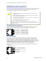
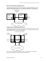
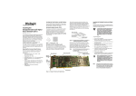
The following illustration shows the cabling required to connect all four trunks on the
TX 4000 board:
Dual T1/E1 120 ohm
adapter cables
Trunks 1 and 3
Trunks 2 and 4
Ethernet 1
Shielded RJ-45 cables
Ethernet 2
TX 4000 board
Dialogic Corporation
11
Installing a Dialogic® TX 4000 PCI SS7 Network Interface Board
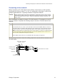
E1 network considerations
TX 4000 boards can support up to four CEPT E1 trunk interfaces. For typical E1
communications, each E1 interface connects directly to an E1 trunk, as shown in the
following illustration:
TX 4000
Public service
telephone network
or proprietary
network
E1 trunk
Note: Trunks do not synchronize until the board is booted with a valid E1
configuration.
T1 network considerations
For typical T1 communications, each trunk interface connects to a channel service
unit (CSU), which is connected to a T1 trunk line. The CSU provides a DSX-1
interface to the T1 line, and also contains circuitry that enables the central office
(CO) to perform diagnostic tests remotely. The following illustration shows the TX
4000 trunk interface with CSU:
TX 4000
DSX-1
interface
CSU
T1
trunk
Public service
telephone network
Note: Trunks do not synchronize until the board is booted with a valid T1
configuration.
You can purchase or lease the CSU from the telephone company or other vendor.
Warning:
Important safety notes for telephony connections:
Use a channel service unit (CSU) to isolate the cables that are attached to this product
before the cables leave the building.
To avoid causing T1 service provider alarms, make sure that the board always sends
a valid signal, either by looping back at the CSU or by connecting the CSU to a
functioning TX 4000 board. The best way to provide a loopback is to unplug the cable
from the TX board to the CSU. The modular connector on most CSUs loops back the
transmit signal to the receive signal when nothing is plugged in.
For information on the cable requirements depending on the target country and
network type, refer to www.dialogic.com/declarations/default.htm.
12
Dialogic Corporation
Installing a Dialogic® TX 4000 PCI SS7 Network Interface Board
Connecting TX boards for redundancy
Use the redundancy feature to enable the system to detect and recover from the
failure of signaling links on a TX 4000 board, the failure of a signaling node, or the
failure of the TX 4000 board itself.
In a redundant configuration, each pair of TX boards is connected through a private
Ethernet connection. If other devices are connected to the private Ethernet link,
avoid overloading the link. Packets can be lost between the redundant TX boards if
the connection is overloaded.
This topic describes dual-node redundant signaling and single-node redundant
signaling for the following types of configurations:
•
TDM configuration
•
IP network configuration
TDM configuration
To connect a TX 4000 board to its redundant mate in a TDM configuration, use a
Category 5 shielded twisted pair (STP) crossover cable. With the crossover cable,
connect Ethernet 1 on the primary board to Ethernet 1 on the backup board.
You must specify the IP address of the TX boards redundant mate using the mate
command in the txconfig utility. You must also specify the IP address and network
mask of Ethernet interface 1 using the ifcreate command in the txconfig utility. For
more information, refer to the Dialogic® NaturalAccess™ Signaling Software
Configuration Manual.
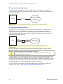
Dual-node redundant signaling server
The following illustration shows how to set up two TX 4000 boards based on a dualnode redundant signaling server in a TDM configuration. The boards are located in
two separate chassis to ensure board-level and system-level redundancy.
SS7 links
Chassis 1
with TX 4000
(primary)
Ethernet 1
Chassis 2
with TX 4000
(backup)
Ethernet 1
Private Ethernet connection
Dialogic Corporation
13
Installing a Dialogic® TX 4000 PCI SS7 Network Interface Board
Single-node redundant signaling server
The following illustration shows how to set up two TX 4000 boards based on the
single-node signaling server in a TDM configuration. The boards are located in the
same chassis to ensure board-level redundancy.
SS7 links
TX 4000
(primary)
Chassis 1
Ethernet 1
TX 4000
(backup)
Ethernet 1
Private Ethernet connection
IP network configuration
To connect a TX 4000 board to its redundant mate in an IP network configuration,
use a Category 5 shielded twisted pair (STP) crossover cable. Using the crossover
cable, connect Ethernet 1 on the primary board to Ethernet 1 on the backup board.
Using standard Ethernet cables, connect the Ethernet 2 connectors on both boards to
the IP network connectors.
Note: Dialogic recommends using a private Ethernet link to connect the redundant
boards to avoid loss or delay of vital checkpoint messages. However, if each board in
the redundant pair requires multi-homing, you can use Ethernet 1 for both the
redundant pathway and for SIGTRAN network access. In this configuration, the
Ethernet 1 on each board is connected to what is shown as an IP network cloud in
the illustrations that follow (just as the Ethernet 2 connectors are). Be aware that
this greatly increases the chance of lost or delayed checkpoint messages which can
result in the backup having outdated information.
You must specify the IP address of the TX boards redundant mate using the mate
command in the txconfig utility. You must also specify the IP address and network
mask of Ethernet interface 1 using the ifcreate command in the txconfig utility. For
more information, refer to the Dialogic® NaturalAccess™ Signaling Software
Configuration Manual.
14
Dialogic Corporation
Installing a Dialogic® TX 4000 PCI SS7 Network Interface Board
Dual-node redundant signaling server
The following illustration shows how to set up two TX 4000 boards based on a dualnode redundant signaling server in an IP network configuration. The boards are
located in two separate chassis to ensure board-level and system-level redundancy.
Private Ethernet
connection
Chassis 2 with
TX 4000
(backup)
Chassis 1 with
TX 4000
(primary)
Ethernet 1
Ethernet 2
Ethernet 1
Ethernet 2
IP network (SIGTRAN)
Single-node redundant signaling server
The following illustration shows how to set up two TX 4000 boards based on a singlenode signaling server in an IP network configuration. The boards are located in the
same chassis to ensure board-level redundancy.
Private Ethernet connection
TX 4000
(primary)
Chassis 1
TX 4000
(backup)
Ethernet 1
Ethernet 1
Ethernet 2
Ethernet 2
IP network (SIGTRAN)
For more information on SS7 redundancy, refer to the Dialogic® TX Series SS7
Boards Health Management Developer's Reference Manual.
Dialogic Corporation
15
Installing a Dialogic® TX 4000 PCI SS7 Network Interface Board
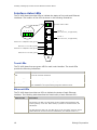
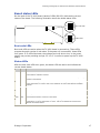
Interface status LEDs
The TX 4000 board provides LEDs to indicate the status of the trunk and Ethernet
interfaces. The location of the LEDs is shown in the following illustration:
Green status LEDs
Trunks
1 2
3
4
Trunk 1
(and Trunk 3, if applicable)
Trunk 2
(and Trunk 4, if applicable)
Ethernet 1 LINK/ACT LED (green)
Ethernet 1 100 LED (green)
Ethernet 2 LINK/ACT LED (green)
Ethernet 2 100 LED (green)
Trunk LEDs
The TX 4000 board has one green LED for each trunk interface. The trunk LEDs
provide the following indications:
Trunk LED
Description
Off
Trunk has not been configured.
Slow blinking green
Indicates loss of signal.
Fast blinking green
Indicates loss of frame or loss of signaling multiframe.
Steady green
Indicates that proper frame synchronization between the trunk and network has
been established. All required framing alignment has been found.
Ethernet LEDs
The TX 4000 board provides two LEDs to indicate the status of each Ethernet
interface. The following table describes the functionality of each Ethernet LED:
Ethernet LED
Description
LINK/ACT
Indicates the status of the Ethernet link. When the Ethernet link has established
link integrity, the LED is on and steady. It also indicates the transmitting and
receiving activity on the link. When activity is present on the Ethernet link, the
LED flickers.
100
Indicates the data rate of the Ethernet link. When the LED is on, the data rate is
100 Mb. When the LED is off, the data rate is 10 Mb. The LED is used only when a
reliable Ethernet connection has been established. (The LINK/ACT LED is on.)
16
Dialogic Corporation
Installing a Dialogic® TX 4000 PCI SS7 Network Interface Board
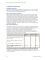
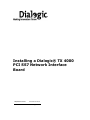
Board status LEDs
On the back of the TX 4000 board, banks of LEDs (D6-D21) indicate the current
status of the board. The following illustration shows the board status LEDs:
D7
D11
D15
D17
D6
D10
D14
D16
D9
D8
D13
D12
D19
D18
D21
D20
Boot code LEDs
Status LEDs
Boot code LEDs
Boot code LEDs are active when the TX 4000 board is powered up. These LEDs
progress through a series of red codes. If the power up is successful, these LEDs
turn green. If no LEDs illuminate, the voltage level may be too low, or the power
supply may not be providing enough 3.3 V or 5 V current to power up the TX 4000
board.
Status LEDs
After the boot code LEDs turn green, the status LEDs are active and indicate the
current board status:
LED
Color
Status when illuminated
D8
Green
Timer interrupt controlled heartbeat. The LED flickers to indicate that the timer
interrupts are operating properly.
D9
Green
Idle task controlled heartbeat. The LED flickers to indicate that the on-board operating
system is operational.
D12
Red
Board is executing in snapshot mode: the board is resetting or txsnap is running. For
more information on txsnap, refer to the Dialogic® TX Series SS7 Boards TX Utilities
Manual.
D13
-----
Reserved for internal use.
D18
Red
Kernel detected a host communication error.
D19
Red
Memory full condition occurred on the board.
D20
Red
Unexpected exception occurred on the board.
D21
Kernel detected a problem. Use the cpcon utility's log command to view error
information. For more information on cpcon, refer to the Dialogic® TX Series SS7
Boards TX Utilities Manual.
Dialogic Corporation
17
Installing a Dialogic® TX 4000 PCI SS7 Network Interface Board
Compliance statements
EU R&TTE statement
This product is intended to be connected to a 2048 kbit/s 75 ohm or 120 ohm digital
structured or unstructured ONP leased line in all EU countries. For more information,
refer to www.dialogic.com/declarations/default.htm.
FCC Part 15 Class A statement
This board has been tested and found to comply with the limits for a Class A digital
device, pursuant to Part 15 of the FCC Rules. These limits are designed to provide
reasonable protection against harmful interference when the equipment is operated
in a commercial environment. This equipment generates, uses and can radiate radio
frequency energy and, if not installed and used in accordance with the instruction
manual, may cause harmful interference to radio communications. Operation of this
equipment in a residential area is likely to cause harmful interference, in which case
the user will be required to correct the interference at his or her own expense.
Modifications not expressly approved by Dialogic may void the FCC granted authority
to operate the equipment.
FCC Part 68 statement
This equipment complies with Part 68 of the FCC rules and the requirements adopted
by the ACTA. On the bottom of this equipment is a label that contains, among other
information, a product identifier in the format US:EMCXDNANXXXXXXXX. If
requested, this number must be provided to the telephone company.
The telephone company will need to know the Service Order Code, the Facility
Interface Code, and the wiring configuration (or USOC jack type) corresponding to
the service you are ordering, as shown in this table:
Service type
Facility
interface
code
Service
order code
USOC
jack
4-wire 1.544 Mbps (DS1) with Super Frame
(SF), Alternate Mark Inversion ("AMI"), no line
power, 100 ohms.
04DU9-BN
6.0N
RJ-48C
4-wire 1.544 Mbps (DS1) with SF, Bipolar with
eight-zero substitution (B8ZS), no line power,
100 ohms.
04DU9-DN
6.0N
RJ-48C
4-wire 1.544 Mbps (DS1) with Extended Super
Frame (ESF), AMI, no line power, 100 ohms.
04DU9-1KN
6.0N
RJ-48C
4-wire 1.544 Mbps (DS1) with ESF, Bipolar with
Eight-Zero Substitution ("B8ZS"), no line
power, 100 ohms.
04DU9-1SN
6.0N
RJ-48C
If this equipment causes harm to the telephone network, the telephone company will
notify you in advance that temporary discontinuance of service may be required. But
if advance notice isn't practical, the telephone company will notify you as soon as
possible. Also, you will be advised of your right to file a complaint with the FCC if you
believe it is necessary.
18
Dialogic Corporation
Installing a Dialogic® TX 4000 PCI SS7 Network Interface Board
The telephone company may make changes in its facilities, equipment, operations or
procedures that could affect the operation of the equipment. If this happens the
telephone company will provide advance notice in order for you to make necessary
modifications to maintain uninterrupted service.
This product is not intended for customer repair.
Canadian ICES-003 statement
This Class A digital apparatus complies with Canadian ICES-003. Cet appareil numérique de la
classe A est conforme à la norme NMB-003 du Canada.
CS-03 statement
This product meets the applicable Industry Canada technical specifications. Le
présent matériel est conforme aux specifications techniques applicables d'Industrie
Canada.
Caution: Users should not attempt to make such connections themselves, but
should contact the appropriate electric inspection authority or electrician.
Europe
Compliance
The Dialogic® products covered by this notice meet the following European
Directives:
2006/95/EC
Safety/Low Voltage Directive
2004/108/EC
EMC Directive
99/05/EC
R&TTE Directive
To achieve CE compliance, be sure to select a host that already meets the EMC and
Low Voltage Directives before the addition of any optional board. Remember that the
use of option boards declared compliant with the Directives by their manufacturer
only gives "presumption of compliance" for the whole system. It is the responsibility
of the system supplier to verify that the requirements of the listed Directives are still
met by the final system, as supplied to the end-user. System integrators should take
notice of further conditions expressed in this section and the Safety section.
The products covered by this notice have been successfully tested against TBR 4
basic call control. Application developers implementing supplementary services at
application level must ensure that their implementation complies with the services
offered by the local Public Switched Telephone Network (PSTN) operator. In case of
doubt, network specifications must be consulted; the R&TTE Directive imposes that
each PSTN operator makes such specifications available.
Inter-working is guaranteed only with Public Switched Telephone Networks (PSTNs)
offering Primary Rate Access conforming to EuroISDN specifications.
Before any connection to PSTN offering Primary Rate Access to other national or
international E1 standards, please consult your Dialogic representative.
Dialogic Corporation
19
Installing a Dialogic® TX 4000 PCI SS7 Network Interface Board
Compliance with the R&TTE Directive
The R&TTE Directive includes its own safety and EMC requirements. Although
equipment declared compliant to the R&TTE Directive does not require explicit
declaration of conformity to EMC and Low Voltage Directives, the above conditions
must also be met to satisfy the safety and EMC requirements of the R&TTE Directive.
Inter-working is guaranteed only with Public Switched Telephone Networks (PSTNs)
as described in the sections above.
Dialogic Declarations of Conformity for these products can be found at:
http://www.dialogic.com/declarations/
Manufacturer's office in European Union:
Dialogic Distribution Limited
Unit 4034
Citywest Business Campus
Saggart, Co. Dublin
IRELAND
Tel: +353 1 630 9000
Fax: +353 1 630 9099
Hereby, Dialogic Corporation, declares that this equipment is in compliance with the
essential requirements and other relevant provisions of European Union Directives
1999/5/EC (R&TTE), 2004/108/EC (EMC Directive) and 2006/95/EC (Low Voltage
Directive).
[Česky]
Dialogic Corporation tímto prohlaauje, ~e tento ITE je ve shode se základními
po~adavky a dalaími prísluanými ustanoveními smernice 1999/5/ES, 2004/108/ES,
2006/95/ES.
[Dansk]
Undertegnede Dialogic Corporation erklærer herved, at følgende udstyr ITE
overholder de væsentlige krav og øvrige relevante krav i direktiv 1999/5/EF,
2004/108/EF, 2006/95/EF.
[Deutsch]
Hiermit erklärt Dialogic Corporation, dass sich das Gerät ITE in Übereinstimmung mit
den grundlegenden Anforderungen und den übrigen einschlägigen Bestimmungen der
Richtlinie 1999/5/EG, 2004/108/EG, 2006/95/EG befindet.
[Eesti]
Käesolevaga kinnitab Dialogic Corporation seadme ITE vastavust direktiivi
1999/5/EÜ, 2004/108/EÜ, 2006/95/EÜ, põhinõuetele ja nimetatud direktiivist
tulenevatele teistele asjakohastele sätetele.
[Español]
Por medio de la presente Dialogic Corporation declara que el ITE cumple con los
requisitos esenciales y cualesquiera otras disposiciones aplicables o exigibles de la
Directiva 1999/5/CE, 2004/108/CE, 2006/95/CE.
20
Dialogic Corporation
Installing a Dialogic® TX 4000 PCI SS7 Network Interface Board
[Ελληνική]
ΜΕ ΤΗΝ ΠΑΡΟΥΣΑ Dialogic Corporation ΔΗΛΩΝΕΙ ΟΤΙ ITE ΣΥΜΜΟΡΦΩΝΕΤΑΙ ΠΡΟΣ
ΤΙΣ ΟΥΣΙΩΔΕΙΣ ΑΠΑΙΤΗΣΕΙΣ ΚΑΙ ΤΙΣ ΛΟΙΠΕΣ ΣΧΕΤΙΚΕΣ ΔΙΑΤΑΞΕΙΣ ΤΗΣ ΟΔΗΓΙΑΣ
1999/5/EK, 2004/108/EK, 2006/95/EK.
[Français]
Par la présente Dialogic Corporation déclare que l'appareil ITE est conforme aux
exigences essentielles et aux autres dispositions pertinentes de la directive
1999/5/CE, 2004/108/CE, 2006/95/CE.
[Italiano]
Con la presente Dialogic Corporation dichiara che questo ITE è conforme ai requisiti
essenziali ed alle altre disposizioni pertinenti stabilite dalla direttiva 1999/5/CE,
2004/108/CE, 2006/95/CE.
[Latviski]
Ar ao Dialogic Corporation deklarē, ka ITE atbilst Direktīvas 1999/5/EK,
2004/108/EK, 2006/95/EK būtiskajām prasībām un citiem ar to saistītajiem
noteikumiem.
[Lietuvių]
`iuo Dialogic Corporation deklaruoja, kad ais ITE atitinka esminius reikalavimus ir
kitas 1999/5/EB, 2004/108/EB, 2006/95/EB, Direktyvos nuostatas.
[Magyar]
Alulírott, Dialogic Corporation nyilatkozom, hogy a ITE megfelel a vonatkozó alapvetõ
követelményeknek és az 1999/5/EK, 2004/108/EK, 2006/95/EK, irányelv egyéb
elõírásainak.
[Malti]
Hawnhekk, Dialogic Corporation, jiddikjara li dan ITE jikkonforma mal-h- tig· jiet
essenzjali u ma provvedimenti oh- rajn relevanti li hemm fid-Dirrettiva 1999/5/KE,
2004/108/KE, 2006/95/KE.
[Nederlands]
Hierbij verklaart Dialogic Corporation dat het toestel ITE in overeenstemming is met
de essentiële eisen en de andere relevante bepalingen van richtlijn 1999/5/EG,
2004/108/EG, 2006/95/EG.
[Polski]
Niniejszym, Dialogic Corporation, oświadcza, że ITE jest zgodny z zasadniczymi
wymogami oraz pozostałymi stosownymi postanowieniami Dyrektywy 1999/5/WE,
2004/108/WE, 2006/95/WE.
[Português]
Dialogic Corporation declara que este ITE está conforme com os requisitos essenciais
e outras disposições da Directiva 1999/5/CE, 2004/108/CE, 2006/95/CE.
Dialogic Corporation
21
Installing a Dialogic® TX 4000 PCI SS7 Network Interface Board
[Slovensko]
Dialogic Corporation izjavlja, da je ta ITE v skladu z bistvenimi zahtevami in ostalimi
relevantnimi določili direktive 1999/5/ES, 2004/108/ES, 2006/95/ES.
[Slovensky]
Dialogic Corporation týmto vyhlasuje, ~e ITE spĺňa základné po~iadavky a vaetky
prísluané ustanovenia Smernice 1999/5/ES, 2004/108/ES, 2006/95/ES.
[Suomi]
Dialogic Corporation vakuuttaa täten että ITE tyyppinen laite on direktiivin
1999/5/EY, 2004/108/EY, 2006/95/EY oleellisten vaatimusten ja sitä koskevien
direktiivin muiden ehtojen mukainen.
[Svenska]
Härmed intygar Dialogic Corporation att denna ITE står I överensstämmelse med de
väsentliga egenskapskrav och övriga relevanta bestämmelser som framgår av
direktiv 1999/5/EG, 2004/108/EG, 2006/95/EG.
[Íslenska]
Hér með lýsir Dialogic Corporation yfir því að ITE er í samræmi við grunnkröfur og
aðrar kröfur, sem gerðar eru í tilskipun 1999/5/EC, 2004/108/EC, 2006/95/EC.
[Norsk]
Dialogic Corporation erklærer herved at utstyret ITE er i samsvar med de
grunnleggende krav og øvrige relevante krav i direktiv 1999/5/EF, 2004/108/EF,
2006/95/EF.
Australia
Dialogic is required to provide the following information as a condition of the
telecommunications conformity of Dialogic® telecommunications products. You may
also be responsible for meeting requirements other than those outlined in this
document.
Note: Failure to meet the requirements listed may render the products noncompliant, with the user liable to significant penalties under the Telecommunications
Act.
Do not connect these products directly to a telecommunications network. These
products must be connected to a network terminating unit (NTU) or some other
device that provides line isolation. This allows the carrier's telecommunications
network to be electrically isolated from the product and host PC.
These products are only to be connected to safety extra low voltage circuits. These
products should only be connected to the safety extra low voltage (SELV) port of the
network termination unit (NTU) or PBX that is providing the E-1 interface.
22
Dialogic Corporation
Installing a Dialogic® TX 4000 PCI SS7 Network Interface Board
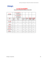
South Korea
명 칭 ( 모 델 명 ) : TX4000
인 증 번 호 : TE-A62/K900-04-0324
인증받은자의 상호 : Dialogic Corporation
제 조 년 월 일 : Marked on serial number tag
제 조 자 / 제 조 국 : Made in USA
Class A statement
This Class A digital apparatus meets all requirements of the Korean EMI regulations.
A급 기기 (업무용 방송통신기기)
이 기기는 업무용(A급)으로 전자파적합등록을 한 기기이오니 판매자 또는 사용자는 이 점을 주의하시기
바라며, 가정외의 지역에서 사용하는 것을 목적으로 합니다.
Telecom regulatory approval of this product is conditional upon the use of suitable
surge suppressors on the E1 interface port(s). The approved 4-wire E1 surge
protector is available from Dialogic as part number 83294 or from Patton Electronics,
part number 552-T1 (www.patton.com).
Dialogic Corporation
23
Installing a Dialogic® TX 4000 PCI SS7 Network Interface Board
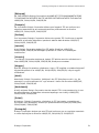
China
24
Dialogic Corporation
Installing a Dialogic® TX 4000 PCI SS7 Network Interface Board
Dialogic Corporation
25
Installing a Dialogic® TX 4000 PCI SS7 Network Interface Board
Product declarations and global approvals
For information about product declarations and global approvals, refer to
www.dialogic.com/declarations/default.htm.
RoHS Statement
For information about RoHS compliance for this product, refer to
www.dialogic.com/rohs/default.htm.
Product environmental information
During August 2005, the European Union Directive on Waste Electrical and Electronic
Equipment (2002/96/EC) and its amendment (2003/108/EC), collectively known as
the WEEE Directive, came into force throughout most of the European Union. This
Dialogic® product comes within the scope of the WEEE Directive. We are confident
that this product will provide you with many years of reliable service.
Moreover, we are pleased to advise you that Dialogic warrants this product, as
detailed in the user guide and provides a fee based repair service when the product
is out of warranty. However, a time will come when the product will no longer meet
your needs or will become un-economic to repair. It is at that stage that we ask for
your co-operation in recycling this product in the spirit of the WEEE directive.
Dialogic has taken great care to minimize the environmental burden of this product
by careful design and manufacturing it under an Environmental Management
System, registered to ISO14001. The requirements of ISO14001 are similar to and
as rigorous as the requirements of ISO9001, Quality Management Systems with
which you may be more familiar. We ask you to help us to ensure that the
environmental burden of this product is minimized when it is of no further use to you
by recycling it. Please do not dispose of this product through municipal or general
waste systems because it contains materials which can be economically recycled.
Like all electrical and electronic equipment, including televisions and computers, it
may contain small amounts of materials which could lead to environmental damage.
To minimize any environmental damage we ask you to have this product recycled
by:
•
Bringing it to the recycling collection point in your company
•
Handing it into the store where you are purchasing the replacement
•
Delivering it to a local bring-centre in your area
No charge can be imposed on you for this recycling service, in the European Union,
as Dialogic has paid for recycling this product when it was placed on the market.
These are requirements of the WEEE directive. We thank you in advance for you cooperation and working with Dialogic in protecting our environment.
Please do not dispose of this product through municipal or general waste,
recycle it.
Limited warranty
For warranty information, refer to www.dialogic.com/warranties.
26
Dialogic Corporation