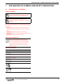
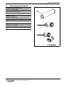
1
INSTALLATION INSTRUCTIONS
7 716 191 159 ROOM SEALED FLUE
80MM FLEXIBLE FLUE SYSTEM
Only for use with Worcester appliances:
Greenstar FS 30CDi Regular and Greenstar FS 42CDi Regular
8 716 115 519a (2009/03)
UK/IE
the nation’s favourite for
PLUMBING & HEATING SUPPLIES
FREE SHIPPING
SECURE PAYMENTS
on all orders over £100 to mainland UK
shop online with confidence
FINANCE AVAILABLE
PRICE MATCH
spread the cost with low interest rates
always get the best deals available
we have
H U G E
R E D U C T I O N S
ON THOUSANDS OF ITEMS
Boilers
Bathroom suites
Radiators
Kitchen sinks & taps
Heating controls
Showers
Pipes & ittings
Wet rooms
Cylinders
Towel warmers
Fires
Bathroom furniture
Renewable energy
& much more
visit our website
plumbnation.co.uk
CALL US ON
0844
800
3460
CONTENTS
CONTENTS
1
EXPLANATION OF SYMBOLS AND
SAFETY PRECAUTIONS . . . . . . . . . . . . . . . . . . . . 3
1.1
Explanation of symbols . . . . . . . . . . . . . . . 3
1.2
Safety precautions . . . . . . . . . . . . . . . . . . 4
2
INSTALLATION REGULATIONS . . . . . . . . . . . . . . 5
3
PRODUCT INFORMATION . . . . . . . . . . . . . . . . . 6
3.1
Flexible flue components . . . . . . . . . . . . . 6
3.2
Flue extension components . . . . . . . . . . . 7
4
PRE-INSTALLATION . . . . . . . . . . . . . . . . . . . . . . 8
4.1
Flexible flue terminal positions . . . . . . . . . 8
4.2
Installation clearances . . . . . . . . . . . . . . . 9
4.3
Requirements for the chimney . . . . . . . . . 9
4.4
Preparing the chimney . . . . . . . . . . . . . . . 9
4.5
Calculating the effective flue length . . . . 10
5
INSTALLATION . . . . . . . . . . . . . . . . . . . . . . . . .
5.1
Creating the chimney hole . . . . . . . . . . .
5.2
Installing the support elbow . . . . . . . . . .
5.3
Assembling the flexible flue . . . . . . . . . .
5.4
Installing the flexible liner assembly . . . .
5.5
Installing the flue terminal . . . . . . . . . . .
5.6
Converting the flue outlet . . . . . . . . . . . .
5.7
Fitting the flue adaptor . . . . . . . . . . . . . .
5.8
Extensions and elbows . . . . . . . . . . . . . .
5.9
Fitting the horizontal flue . . . . . . . . . . . .
6
SERVICING AND SPARES . . . . . . . . . . . . . . . . . 26
6.1
Servicing . . . . . . . . . . . . . . . . . . . . . . . . . 26
6.2
Spare parts . . . . . . . . . . . . . . . . . . . . . . . 27
2
11
11
12
13
16
19
20
21
22
24
8 716 115 519a (2009/03)
EXPLANATION OF SYMBOLS AND SAFETY PRECAUTIONS
1
EXPLANATION OF SYMBOLS AND SAFETY PRECAUTIONS
1.1
EXPLANATION OF SYMBOLS
WARNING SYMBOLS
Safety instructions in this document are
framed and identified by a warning triangle
which is printed on a grey background.
Electrical hazards are identified by a
lightning symbol surrounded by a warning
triangle.
Signal words indicate the seriousness of the hazard in
terms of the consequences of not following the safety
instructions.
• NOTICE indicates possible damage to property or
equipment, but where there is no risk of personal
injury.
• CAUTION indicates possible personal injury.
• WARNING indicates possible severe personal injury.
• DANGER indicates possible risk to life.
IMPORTANT INFORMATION
Notes contain important information in
cases where there is no risk of personal
injury or material losses and are identified
by the symbol shown on the left. They are
bordered by horizontal lines above and
below the text.
ADDITIONAL SYMBOLS
Symbol
Meaning
B
step in an action sequence
å
reference to a related part in the
document or to other related documents
•
list entry
–
Ø
list entry (second level)
Diameter
Cutting required
Drilling required
Table 1:
8 716 115 519a (2009/03)
3
EXPLANATION OF SYMBOLS AND SAFETY PRECAUTIONS
1.2
SAFETY PRECAUTIONS
PLEASE READ THESE INSTRUCTIONS CAREFULLY
BEFORE STARTING INSTALLATION:
These installation instructions are applicable to the
Worcester flue kit stated on the front cover of this
manual and must not be used with any other make or
model.
These installation instructions must be read in
conjunction with the appliance manual.
The instructions apply in the UK/IE only and must be
followed except for any statutory obligation.
This flue kit must be installed by a CORGI registered,
competent person. Failure to install correctly could lead
to prosecution.
If you are in any doubt contact the Worcester technical
helpline.
Distance learning and training courses are available from
Worcester.
FITTING AND MODIFICATIONS:
Fitting the flue system to the appliance must be carried
out by a CORGI registered, competent person in
accordance with these installation instructions and the
current Gas Safety Regulations (Installation and Use).
Worcester, Bosch Group recommends that this flue
system is installed by two persons for easier handling of
the components.
Flue systems must not be modified in any way other
than as described in the fitting instructions. Any
misuse or unauthorised modifications to the appliance,
flue or associated components and systems will
invalidate the warranty. The manufacturer accepts no
liability arising from any such actions, excluding
statutory rights.
B Position the flue terminal in such a way so that
combustion products do not enter the building or
cause a nuisance.
B Position the flue in such a way so the flue does not
cause an obstruction.
BENCHMARK:
Please leave these instructions with the completed
Benchmark checklist (or a certificate confirming
compliance with IS 813, EIRE only) with the owner
after installation or servicing.
The Benchmark checklist can be found in the back
two pages of the appliance installation manual.
IF YOU SMELL GAS:
B Do not smoke or strike matches.
B Do not turn electrical switches ON or OFF.
B Put out naked flames.
B Open doors and windows.
B Keep people away from the affected area.
B Turn off the control valve at the meter.
B Call your gas company.
B Ensure the flue terminal is not obstructed and
combustion products can discharge without
hindrance.
B Fit the flue according to the regulations and
standards stated on page 5.
SERVICING:
Advise the user to have the system serviced annually by
a CORGI registered, competent person using approved
spares, to help maintain the economy, safety and
reliability of the appliance.
B The service engineer must complete the
Service Record on the Benchmark Checklist after
each service.
OR
B Call emergency number 0800 111 999.
USE
This flexible flue system is only suitable for lining
chimneys that conform to the building regulations.
B Do not use this flexible flue as a chimney on its own.
B Do not use this flexible flue outside a masonry or
flueblock chimney.
WORKING AT HEIGHTS:
B Refer to the applicable health & safety regulations.
4
8 716 115 519a (2009/03)
INSTALLATION REGULATIONS
2
INSTALLATION REGULATIONS
Current Gas Safety Regulations
(Installation and Use):
Failure to install flue systems correctly
could lead to prosecution.
All flue systems and associated components
must be installed by a CORGI registered,
competent person in accordance with the
following regulations.
Relevant regulations:
• Gas Safety Regulations 1998 (Installation and Use)
• Building Regulations
• Building Regulations (Northern Ireland)
• Building Standards (Scotland) (Consolidation)
• IS 813 (Eire)
• IGE “Gas Installation in Timber Frame Buildings”
• Any other local requirement
The relevant British Standards to be followed, include:
BS5440: 1
Flues and ventilation for gas appliances
of rated input not exceeding 70kW
(net): Flues
BS5440: 2
Flues and ventilation for gas appliances
of rated input not exceeding 70kW
(net): Air Supply
BS6798:
2000
Specification for installation of gas fired
boilers of rated input not exceeding
70kW net
Table 2:
Relevant British Standards
If no specific instruction is given, refer to the
British Standard Codes of Practice.
8 716 115 519a (2009/03)
5
PRODUCT INFORMATION
3
PRODUCT INFORMATION
3.1
FLEXIBLE FLUE COMPONENTS
No.
Description
Quantity
1
Flue terminal
1
2
Chimney cowl
1
3
Self-adhesive weather seal
1
4
Terminal adaptor
1
5
Support bracket assembly
1
6
Liner
2
7
Seal
2
8
Flexible liner
1
9
Centralising spacer
4
10
Support elbow adaptor
1
11
Support elbow
1
12
Elbow support
1
13
Flue inspection plates
2
14
Seal for flue inspection plates
1
15
125mm flue extension
1
16
Tee piece
1
17
125mm flue connector
1
18
80/80mm flue adaptor
1
Table 3:
6
Contents of package
8 716 115 519a (2009/03)
PRODUCT INFORMATION
3.2
FLUE EXTENSION COMPONENTS
Ø 80/125 1000mm Extension kit
(Part No: 7 719 001 892)
1
Extension tube assembly
Table 4:
Extension kit contents
Ø 80/125 90° bend
(Part No: 7 719 001 891)
2
90° bend
Table 5:
90°bend contents
Ø 80/125 45° bends
(Part No: 7 719 001 899)
3
45° bend x2
Table 6:
45° bends contents
Fig. 1
8 716 115 519a (2009/03)
Extension components
7
PRE-INSTALLATION
4
PRE-INSTALLATION
NOTICE:
Risk of damage to the appliance or flue.
B Read all Pre-Installation sections.
B Ensure all requirements are met before using the appliance or flue installation.
4.1
FLEXIBLE FLUE TERMINAL POSITIONS
Flue gases have a tendency to plume and in
certain weather conditions a white plume of
condensation may be discharged from the
flue outlet.
Where this could cause a nuisance, for
example near security lighting, an alternate
flue position should be found.
Fig. 2
The flue terminal positions must also follow
those stated in the relevant appliance
installation manual.
Flexible flue terminal positions and clearances
Minimum clearances
1
500mm to non-combustible building material or 1,500mm to combustible building material
2
600mm to another vertical flue terminal
3
600mm above and to either side of a Velux window and 2,000mm below a Velux window
4
1500mm above and to either side of a Dormer window
5
400mm to a pitched roof (500mm in regions with heavy snow fall)
Table 7:
8
Minimum clearances
8 716 115 519a (2009/03)
PRE-INSTALLATION
4.2
INSTALLATION CLEARANCES
For information regarding installation
clearances please refer to the appliance
installation manual.
4.3
REQUIREMENTS FOR THE CHIMNEY
CHIMNEY SIZE
Before starting with the flue installation:
B Ensure the cross section of the chimney complies
with table 8 below and figure 3 opposite.
cmin
cmax
Ø dmin
Ø dmax
130mm
300mm
146mm
300mm
Table 8:
Fig. 3
Chimney sizes
Chimney sizes
FIRE RESISTANCE
The materials used for the construction of the chimney
must be fire resistant in compliance with the figures
stated below.
Type of building
Fire resistance
single storey building
30 minutes
multi storey building
90 minutes
Table 9:
4.4
Fire resistance of chimney material
PREPARING THE CHIMNEY
• The chimney must be swept if it has been previously
used for an appliance burning a fuel other than gas.
• It is recommended that the chimney be swept before
installation of the flexible flue.
• Any damper or restrictor plate in the chimney must be
removed.
If it is not possible to remove the sliding damper it
must be fixed permanently in the open position.
• Any holes in the chimney must be sealed.
• The existing chimney pot and flaunching must be
removed.
• The catchment space (void below the point of flue
connection) must be checked to ensure it complies
with the flue to be installed.
• All debris must be cleared from the catchment space.
• To avoid debris falling into the air inlet duct, do not
install the duct with the open end facing up the
chimney.
Only one appliance can be fitted to the
flexible flue system.
8 716 115 519a (2009/03)
9
PRE-INSTALLATION
4.5
CALCULATING THE EFFECTIVE FLUE LENGTH
appliance
variant
max flue length
vertical
(Lvmax)
max flue length
horizontal
(Lhmax)
FS 30CDi
12m
3m
FS 42CDi
12m
3m
Table 10: Maximum flue length
To calculate the effective flue length:
B Check the flue path and consider the following:
– number of 90° and 45° elbows required outside
the chimney
– number of bends in the flexible liner
B Deduct the effective length of each elbow from the
maximum horizontal flue length of 3m.
80/125 mm elbow
Effective length (m)
90°
2m
45°
1m
Table 11: Elbow equivalent lengths
B Deduct the effective lengths of each bend from the
maximum vertical flue length (Lvmax) of 12m.
Bend in 80mm flexible liner
Effective length (m)
45°
1.5m
Table 12: Bend equivalent lengths
Fig. 4
Maximum flue length
EXAMPLE OF EFFECTIVE FLUE LENGTH CALCULATION (FOR FIGURE 4)
This example shows the use of the flexible flue kit
without additional extensions or elbows.
Horizontal effective flue length
(no extensions or elbows)
Lh = 1m
Lh ≤ Lhmax ?
Lhmax = 3m
OK
Tab. 13: Example: horizontal flue length
Vertical effective flue length
(with 2x 45° bends)
Lvmax
= 12m
-
2x 45° bend
= 3m
Lv ?
=
9m
Tab. 14: Example: vertical flue length
10
8 716 115 519a (2009/03)
INSTALLATION
5
INSTALLATION
5.1
CREATING THE CHIMNEY HOLE
WARNING:
To avoid debris falling into the air inlet duct, do not install the duct with the open end facing up the
chimney.
The horizontal flue pipe connecting
appliance and flexible liner must rise by at
least 52mm for every metre of length.
This is to ensure the condensate flows back
into the appliance.
B Ensure the lower edge of the chimney
hole is higher than the appliance.
As shown in fig. 5, the height h is dependant on the
distance d. For every metre the appliance is away from
the chimney wall the height must rise by at least 52mm.
The further away the appliance stands from the chimney
wall, the higher the lower edge of the chimney hole must
be.
The chimney hole must be large enough to install the flue
and allow access to the joints for servicing.
B Make an opening in the chimney wall according to the
measurements shown in fig. 6.
B Mark the position of elbow support, ensuring that the
mark is centred within the opening made in the
chimney wall.
B Drill a Ø 10mm hole 60mm deep into the chimney
wall.
Fig. 5
Positioning the chimney hole
Fig. 6
Chimney hole
An additional hole is required to secure the support bar.
B Drill a hole into the ledge of the chimney hole as
shown opposite, ensure that the hole is centrally
located in the opening.
B Insert a suitable wall plug.
=
Fig. 7
8 716 115 519a (2009/03)
=
Drilling securing hole
11
INSTALLATION
5.2
INSTALLING THE SUPPORT ELBOW
Depending on the depth of the chimney, it may be
necessary to cut the support bar.
B Cut the support bar to fit the chimney as in fig. 8.
B Drill a new hole into the support bar.
Ensure it will match with the securing hole in the
ledge.
Fig. 8
Cutting the support bar
Fig. 9
Fitting the elbow onto the elbow support
B Measure the depth of the chimney.
B Position the elbow centrally on the elbow support as
shown in fig. 9.
B Secure with the wing nut.
B Grease the seal in the elbow.
B Place the elbow assembly in the chimney.
B Ensure that the elbow support is horizontal and the
elbow centrally positioned with the chimney space.
B Secure the assembly with a screw as shown in fig. 10.
Fig. 10 Placing the elbow assembly into the chimney
12
8 716 115 519a (2009/03)
INSTALLATION
5.3
ASSEMBLING THE FLEXIBLE FLUE
B Use a hack saw.
B Cut the flexible liner off square directly below a set of
ridges.
B Do not cut between the individual ridges of a set.
Fig. 11 Where to cut the flexible liner
1. Remove the liner and seal from the adaptor.
2. Remove the seal (b) from the liner (a).
a
b
Fig. 12 Removing liner and seal from adaptor
3. Use a screwdriver to release the locking tab.
4. Rotate the moveable band anti-clockwise to open
the bayonet release.
Fig. 13 Opening the bayonet release
8 716 115 519a (2009/03)
13
INSTALLATION
5. Fit the seal (b) into the first wide recess on the
flexible liner (c). Make sure the seal (b) is not
twisted and is seated properly.
6. Fit the liner (a) into the flexible liner (c).
7. Grease the seal (b).
b
c
a
b
Fig. 14 Fitting the seal and liner
8. Push the adaptor onto the flexible liner until it
“bottoms out” and the moveable band “clicks” into
place.
If the band does not “click” into place, check:
B the adaptor is pushed down fully
B the adaptor is square to the flexible liner
B the lugs are aligned with their slots in the adaptor
B that the flexible liner is cut correctly
B refer to fig. 16 for help
9. Rotate the moveable band clockwise until it locks in
place.
Fig. 15 Fitting the adaptor onto the flexible liner
Fig. 16 Cutaway view of adaptor fitted to flexible liner
14
8 716 115 519a (2009/03)
INSTALLATION
The centralising spacer must be shortened to fit the
80mm flexible liner.
10. Snap off the centralising spacer at the perforated
section marked 80mm to suit the flue.
Fig. 17 Shortening the centralising spacer
11. Secure the centralising spacer around the flexible
liner as shown in fig. 18.
Fig. 18 Fitting the centralising spacer
The centralising spacers must be fitted to the flexible
liner in certain positions to ensure the liner is centred
within the chimney.
B For a chimney with a bend place the centralising
spacers at positions shown opposite.
B Place a centralising spacer at least every 2500mm on
the vertical parts of the chimney.
Fig. 19 Positioning the centralising spacers
8 716 115 519a (2009/03)
15
INSTALLATION
5.4
INSTALLING THE FLEXIBLE LINER ASSEMBLY
To ease the assembly of the flue
components:
B Grease all seals lightly with solvent-free
grease .
B Ensure all seals are seated properly and
are in good condition.
1. Feed the flexible liner assembly into the chimney
from the top.
2. Insert the adaptor into the support elbow.
Fig. 20 Feeding the liner assembly into the chimney
16
8 716 115 519a (2009/03)
INSTALLATION
3. Fit the support collar onto the flexible liner.
Ensure the retaining ring at the top of the collar is
seated in a ring of the corrugated section as shown
opposite.
4. Assemble the support bracket onto the support
collar.
In order to install the terminal adaptor, there
must be at least three corrugated sections of
the flexible liner left above the support
bracket assembly.
Fig. 21 Fitting support collar and support bracket
The flexible flue must be centrally aligned within in the
chimney.
5. Mark the support bracket fixing points.
Drill the fixing points.
Secure the support bracket to the chimney.
Fig. 22 Fixing support collar to chimney top
8 716 115 519a (2009/03)
17
INSTALLATION
The flexible flue must now be prepared so the terminal
adaptor can be fitted.
6. Cut the flexible liner three complete corrugated
sections above the support collar.
Ensure to cut at the bottom of the wide recess
directly above the corrugated section.
7. Grease the seal.
8. Fit the seal into the first wide recess on the flexible
liner. Make sure the seal is not twisted and is seated
properly.
Fig. 23 Cutting flexible liner and fitting seal
To reinforce the end of the flexible liner:
9. Fit the liner into the flexible liner.
Fig. 24 Fitting the liner into the flexible liner
The terminal adaptor can now be fitted to the flexible
liner.
B Refer to pages 13 and 14 for additional
information on how to prepare the
terminal adaptor.
10. Push the terminal adaptor onto the flexible liner
until it “bottoms out” and the movable band “clicks”
into place.
If the band does not “click” into place, check:
B the adaptor is pushed down fully
B the adaptor is square to the flexible liner
B the lugs are aligned with their slots in the adaptor
B that the flexible liner is cut correctly
11. Rotate the movable band anti-clockwise until it locks
in place.
12. Grease the adaptor seal.
18
Fig. 25 Fitting the terminal adaptor
8 716 115 519a (2009/03)
INSTALLATION
5.5
INSTALLING THE FLUE TERMINAL
To ease the assembly of the flue
components:
B Grease all seals lightly with solvent-free
grease .
B Ensure all seals are seated properly and
are in good condition.
B Fit the terminal into the terminal adaptor.
B Check the height is a minimum of 350mm from the top
of chimney to the top of terminal.
B Remove the terminal from the terminal adaptor.
Fig. 26 Checking the height
B Fit the self-adhesive weather seal to the base of the
chimney cowl.
B Fit the terminal through the chimney cowl.
B Re-insert the terminal into the terminal adaptor.
B Mark the cowl securing points.
B Rotate the chimney cowl to drill.
B Insert wall plugs.
B Rotate chimney cowl back.
B Secure chimney cowl with the screws provided.
If the chimney cowl is too large:
B Cut the chimney cowl down along the
moulded marks and use the inner set of
securing points.
Fig. 27 Fitting the chimney cowl
8 716 115 519a (2009/03)
19
INSTALLATION
5.6
CONVERTING THE FLUE OUTLET
The appliance is supplied ready to have a flue fitted to
the rear flue outlet.
To convert the flue from the rear to the top of the
appliance, follow the procedure below:
1. Remove the “knock-out” panel from the top
outer casing.
2. Remove the screws, blanking plate and gasket from
the top flue outlet.
Refer to the appliance installation manual for
information on how to disassemble the
casing.
Fig. 28 Preparing the appliance
3. Use the screws to refit gasket and blanking plate
over the rear flue outlet.
Fig. 29 Closing the rear flue outlet
20
8 716 115 519a (2009/03)
INSTALLATION
5.7
FITTING THE FLUE ADAPTOR
To ease the assembly of the flue
components:
B Grease all seals lightly with solvent-free
grease .
B Ensure all seals are seated properly and
are in good condition.
1. Fit the flue connector to the appliance.
2. Ensure the connector‘s flat section is at the rear edge
of the inner casing.
Fig. 30 Fitting the flue connector to the appliance
3. Secure the connector from inside the inner casing
using three hexagonal bolts.
4. Insert the adaptor through the flue outlet hole on
top of the appliance.
5. Push the adaptor into the appliance flue outlet tube
until the retaining clips secure the adaptor.
Fig. 31 Making the flue connection inside the appliance
8 716 115 519a (2009/03)
21
INSTALLATION
5.8
EXTENSIONS AND ELBOWS
Connecting flue bends increases the
effective flue length and allowance must be
made for the different connectors.
The examples opposite show the dimensions for:
• a 90° elbow and the tee piece connected together
• two 45° elbows connected together
To calculate the effective flue length:
B Identify the number of 90° and 45° elbows required.
B Deduct the effective length of each elbow from the
maximum horizontal flue length of 3m.
80/125 mm elbow
Effective length (m)
90°
2m
45°
1m
180m
Fig. 32 Elbow measurements
Table 15: Elbow equivalent lengths
To reduce the length of a flue extension:
B Mark the flue extension to the required distance,
measuring from the socket end as shown in fig. 33.
B Cut the flue extension square, taking care not to
damage the tubes.
B Remove any burrs and chamfer the outer edges of the
tubes to prevent seal damage.
Only straight flue extensions may be cut.
B Do not modify flue elbows or the
tee piece.
Fig. 33 Cutting a flue extension
The flue pipe must not be closer than 25mm
to any combustible material.
The tee piece has a built-in angle of 3°.
All horizontal sections of the flue must rise
by 3° or at least 52mm for each metre away
from the appliance as shown opposite.
This is to ensure the condensate flows back
into the appliance.
22
Fig. 34 Horizontal flue inclination
8 716 115 519a (2009/03)
INSTALLATION
To install flue extensions:
1. Slide a bracket onto each additional straight flue
extension.
Working from the appliance, fit extensions with
brackets as required to support the weight of the
flue.
2. Drill two holes (180° apart if possible) through the
outer collar of each flue tube and use screws to
secure the connection.
NOTICE:
Take care not to drill the inner flue tube.
B The appliance might go into lockout due
to flue gases mixing with combustion air.
8 716 115 519a (2009/03)
Fig. 35 Assembling extensions and elbows
23
INSTALLATION
5.9
FITTING THE HORIZONTAL FLUE
To ease the assembly of the flue
components:
B Grease all seals lightly with solvent-free
grease .
B Ensure all seals are seated properly and
are in good condition.
1. Slide the seal from the inspection plate
assembly over the flue pipe.
Fig. 36 Slide the seal over flue pipe
2. Fit the tee piece to the flue pipe.
Secure with two screws in the same manner as
described on page 23.
3. Fit the flue pipe to the elbow in the chimney.
Fig. 37 Connecting tee piece and flue pipe to elbow
4. Connect the tee piece to the appliance flue outlet.
Secure the tee piece to the connector with the two
screws provided.
Fig. 38 Connecting tee piece to appliance flue outlet
24
8 716 115 519a (2009/03)
INSTALLATION
5. Align the two inspection plates with the seal.
6. Screw the two plates together with four self tapping
screws.
7. Check the rubber gasket is seated properly as
shown in fig. 39.
Fig. 39 Assembling flue inspection plates
8. Align the inspection plate over the chimney opening,
mark and drill four fixing holes.
9. Fix the inspection plate to the chimney with the
screws and wall plugs provided.
Fig. 40 Fixing inspection plates to chimney
8 716 115 519a (2009/03)
25
SERVICING AND SPARES
6
SERVICING AND SPARES
6.1
SERVICING
An annual visual check of the flue system
must be performed.
To perform the visual check of the flue system:
1. Rotate and remove the end cover from the tee piece.
2. Unscrew and remove the inner flue end cover
3. Remove the screws that secure the inspection plate
and slide the inspection plate away from the chimney.
Replace all end covers and the inspection plate after
visual inspection of the flue system.
Fig. 41 Performing the visual check
26
8 716 115 519a (2009/03)
SERVICING AND SPARES
6.2
SPARE PARTS
This table contains the available spare parts for the
80mm flexible flue kit.
No.
Description
Part No.
1
Flue connector
8 718 682 378 0
2
Flue adaptor
8 718 682 380 0
Table 16: Spare parts
Fig. 42 Available spare parts
8 716 115 519a (2009/03)
27
CONTACT INFORMATION
WORCESTER, BOSCH GROUP:
TECHNICAL:
08705 266241
CONTACT CENTRE:
08457 256206
CONTACT CENTRE (IE): 01494 0099
SPARES:
01905 752571
LITERATURE:
01905 752556
TRAINING:
01905 752526
SALES:
01905 752640
WEBSITE:
Dedicated to heating comfort
Worcester, Bosch Group
Cotswold Way, Warndon, Worcester WR4 9SW
Tel. 01905 754624 Fax. 01905 754619
Worcester, Bosch Group is a brand name of Bosch Thermotechnology Ltd.
www.worcester-bosch.co.uk
8 716 115 519a
www.worcester-bosch.co.uk