1
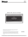
Owners Manual MVP841 DVD / Video CD / CD Player Manufactured under license from Dolby Laboratories. Dolby, and the double-D symbol are trademarks of Dolby Laboratories. Confidential Unpublished Works. © 1992-1977 Dolby Laboratories, Inc. All rights reserved. This product incorporates copyright protection technology that is protected by method claims of certain U.S. Patents and other intellectual property rights owned by Macrovision Corporation and other rights owners. Use of this copyright protection technology must be authorized by Macrovision Corporation, and is intended for home and other limited viewing uses only unless otherwise authorized by Macrovision Corporation. Reverse engineering or disassembly is prohibited. MVP841 McIntosh Laboratory, Inc. 2 Chambers Street Binghamton, New York 13903-2699 Phone: 607-723-3512 FAX: 607-724-0549 Thank You Table of Contents Your decision to own this McIntosh MVP841 DVD/Video CD/CD Player ranks you at the very top among discriminating music listeners. You now have The Best. The McIntosh dedication to Quality, is assurance that you will receive many years of musical enjoyment from this unit. Please take a short time to read the information in this manual. We want you to be as familiar as possible with all the features and functions of your new McIntosh. Thank You ......................................................................... 2 Please Take a Moment ...................................................... 2 Technical Assistance and Customer Service .................... 2 Table of Contents .............................................................. 2 Safety Instructions ............................................................ 3 Introduction and Performance Features ............................ 5 Dimensions ....................................................................... 6 Installation ........................................................................ 7 Rear Panel Connections and Switch ................................. 8 How to Connect Control, Analog and Digital Audio ....... 9 How to Connect Video and AC Power ........................... 10 Front Panel Display, Indicators, Push-Buttons and Switch ...................................................................... 11 Remote Control Push-Buttons ........................................ 12 How to Operate the Remote Control .............................. 13 How to Operate the Setup Mode .................................... 14 How to Operate the MVP841 ......................................... 24 Specifications ................................................................. 30 Packing Instruction ......................................................... 31 Please Take A Moment The serial number, purchase date and McIntosh dealer name are important to you for possible insurance claim or future service. The spaces below have been provided for you to record that information: Serial Number: Purchase Date: Dealer Name: General Notes Technical Assistance If at any time you have questions about your McIntosh product, contact your McIntosh dealer who is familiar with your McIntosh equipment and any other brands that may be part of your system. If you or your dealer wish additional help concerning a suspected problem, you can receive technical assistance for all McIntosh products at: McIntosh Laboratory, Inc. 2 Chambers Street Binghamton, New York 13903 Phone: 607-723-3512 Fax: 607-723-3636 Customer Service If it is determined that your McIntosh product is in need of repair, you can return it to your dealer. You can also return it to the McIntosh Laboratory Service Repair Department. For assistance on factory repair return procedure, contact the McIntosh Repair Department at: McIntosh Laboratory, Inc. 2 Chambers Street Binghamton, New York 13903 Phone: 607-723-3515 Fax: 607-723-1917 Copyright 2000 ã by McIntosh Laboratory, Inc. 2 1. The following Connecting Cable is available from the McIntosh Parts Department: Data and Power Control Cable Part No. 170-202 Six foot, shielded 2 conductor, with 1/8 inch stereo mini phone plugs on each end. 2. For additional connection information, refer to the owners manual(s) for any component(s) connected to the MVP841 Video Disc Player. 3. The MVP841 has a built-in 24 Bit 96kHz DAC (Digital to Analog Converter) to allow playing of DVDs recorded with a higher bit and sample rate by using the Analog Audio Outputs. 4. Several of the DVD performance features available on the MVP841 are active only if the DVD includes the supporting encoded information. 5. The translucent Remote Control push-button, except for the Setup push-button, will illuminate for approximately 3 seconds when activated. 6. When AC power is turned off, the MVP841 front panel nomenclature will remain On for a few seconds. 7. The MVP841 will automatically power down to a STANDBY Mode 30 minutes after a disc has stopped playing. 8. The MVP841 will play manufactured DVD, Video CD and CD Audio Discs. CD-R Discs that are recorded have a different color reflective layer, from the standard manufactured discs, and may not play in the MVP841. 9. The MVP841 basic transport functions may also be controlled by using the remote control that comes with a McIntosh Control Center or Preamp. McIntosh Keypads connected to a McIntosh Control Center or Preamp will also allow remote operation of the MVP841. Safety Instructions IMPORTANT SAFETY INSTRUCTIONS! PLEASE READ THEM BEFORE OPERATING THIS EQUIPMENT. WARNING SHOCK HAZARD DO NOT OPEN The lightning flash with arrowhead, within an equilateral triangle, is intended to alert the user to the presence of uninsulated dangerous voltage within the products enclosure that may be of sufficient magnitude to constitute a risk of electric shock to persons. AVIS RISQUE DE CHOC NE PAS OUVRIR The exclamation point within an equilateral triangle is intended to alert the user to the presence of important operating and maintenance (servicing) instructions in the literature accompanying the appliance. NO USER-SERVICEABLE PARTS INSIDE. REFER SERVICING TO QUALIFIED PERSONNEL To prevent the risk of electric shock, do not remove cover (or back). No user serviceable parts inside. Refer servicing to qualified personnel. CAUTION - Invisible Laser Radiation when open. DO NOT stare into the beam or view directly with optical instruments. Use of controls or adjustment or performance of procedures other than those specified in the Owners Manual may result in Hazardous Radiation Exposure. LUOKAN 1 LASERLAITE KLASS 1 LASER APPARAT VAROITUS! Laitteen kayttaminen muulla kuin tassa kayttoohjeessa mainitulla tavalla saattaa altistaa kayttajan turvallisuusluokan 1 ylittavalle nakymattomalle lasersateiiylle. VARNING! Om apparaten anvands pa annat satt an i denna bruksanvisning specificerats, kan anvandaren utsattas for osynbg laserstraining, som overskrider gransen for laserklass 1. This product incorporates an embedded CLASS 2 Laser (IEC 825). General: 1. Read all the safety and operating instructions, contained in this owners manual, before operating this equipment. 2. Retain this owners manual for future reference about safety and operating instructions. 3. Adhere to all warnings and operating instructions. 4. Follow all operating and use instructions. 5. Warning: To reduce risk of fire or electrical shock, do not expose this equipment to rain or moisture. This unit is capable of producing high sound pressure levels. Continued exposure to high sound pressure levels can cause permanent hearing impairment or loss. User caution is advised and ear protection is recommended when playing at high volumes. 6. Caution: to prevent electrical shock do not use this (polarized) plug with an extension cord, receptacle or other outlet unless the blades can be fully inserted to prevent blade exposure. 3 Safety Instructions cont Attention: pour pevenir les chocs elecriques pas utiliser cette fiche polarisee avec un prolongateur, une prise de courant ou un autre sortie de courant, sauf si les lames peuvent etre inserees afond ans en laisser aucune partie a decouvert. 7. For added protection for this product during a lightning storm, or when it is left unattended and unused for long periods of time, unplug it from the wall outlet. This will prevent damage to the product due to lightning or power line surges. 8. Do not use attachments not recommended in this owners manual as they may cause hazards. Installation: 9. Locate the equipment for proper ventilation. For example, the equipment should not be placed on a bed, sofa, rug, or similar surface that may block ventilation openings; or, placed in a built-in installation, such as a bookcase or cabinet, that may impede the flow of air through the ventilation openings. 10. Locate the equipment away from heat sources such as radiators, heat registers, stoves, or other appliance(s) (including amplifiers) that produce heat. 11. Mount the equipment in a wall or cabinet only as described in this owners manual. 12. Do not use this equipment near water; for example, near a bathtub, washbowl, kitchen sink, laundry tub, in a wet basement or near a swimming pool, etc. 13. Do not place this product on an unstable cart, stand, tripod, bracket, or table. The equipment may fall, causing serious injury to a person, and serious damage to the product. Connection: 14. Connect this equipment only to the type of AC power source as marked on the unit. 15. Route AC power cords so that they are not likely to be walked on or pinched by items placed upon or against them, paying particular attention to cords at plugs, convenience receptacles, and the point where they exit from the instrument. 16. Do not defeat the inherent design features of the polarized plug. Non-polarized line cord adapters will defeat the safety provided by the polarized AC plug. If the plug should fail to fit, contact your electrician to replace your obsolete outlet. Do not defeat the safety purpose of the grounding-type plug. 17. Do not overload wall outlets, extension cords or integral convenience receptacles as this can result in a risk of fire or electric shock. 4 Care of Equipment: 18. Clean the instrument by dusting with a dry cloth. Unplug this equipment from the wall outlet and clean the panel with a cloth moistened with a window cleaner. Do not use liquid cleaners or aerosol cleaners. 19. Do not permit objects or liquids of any kind to be pushed, spilled and/or fall into the equipment through enclosure openings. 20. Unplug the power cord from the AC power outlet when left unused for a long period of time. Repair of Equipment: 21. Unplug this equipment from the wall outlet and refer servicing to a qualified service personnel under the following conditions: A. The AC power cord or the plug has been damaged. B. Objects have fallen, or liquid has been spilled into the equipment. C. The equipment has been exposed to rain or water. D. The equipment does not operate normally by following the operating instructions contained within this owners manual. Adjust only those controls that are covered by the operating instructions, as an improper adjustment of other controls may result in damage and will often require extensive work by a qualified technician to restore the product to its normal operation. E. The equipment has been dropped or damaged in any way. F. The equipment exhibits a distinct change in performance - this indicates a need for service. 22. Do not attempt to service beyond that described in the operating instructions. All other service should be referred to qualified service personnel. 23. When replacement parts are required, be sure the service technician has used replacement parts specified by McIntosh or have the same characteristics as the original part. Unauthorized substitutions may result in fire, electric shock, or other hazards. 24. Upon completion of any service or repairs to this product, ask the service technician to perform safety checks to determine that the product is in proper operating condition. Introduction and Performance Features Introduction The McIntosh MVP841 DVD/Video CD/CD Player offers the latest in audio/video technology to provide state of the art reproduction of digital video and audio program sources. A full complement of performance features gives you the opportunity to enjoy all the special audio and video formats available on a DVD. Audio CDs are also reproduced with flawless realism. The advanced mechanical design of the transport ensures many years of smooth trouble free operation. Dolby Digital and DTS Digital Output The MVP841 provides either the Dolby Digital or the DTS Digital Output for an external decoder, both coaxial and optical outputs are provided. Performance Features Still Picture Display The Still Picture Display Mode allows selection of three different Still Picure Image qualities. The I Image offers the best picture quality, the P and B Images are generated from the differences between successive I Images. Dual-Focus Hologram Laser Lens The MVP841 incorporates a dual-focus hologram lens that splits the beam of the already superfine laser so it can read two disc layers simultaneously. This unique design eliminates the need for two separate laser systems and ensures full compatibility with your existing CD library. The unique MVP841 Red Laser has a thinner beam with a shorter wavelength to more accurately read the denselypacked 4.7 gigabytes of information on a single layer of a DVD disc. Advanced Transport The MVP841 has a new mechanism with the advanced digital servo for faster, quieter and accurate operation.The transport has side suspension dampers for improved trackability and lower bit error rate. Also included is a new hydrodynamic bearing spindle motor. These mechanical innovations ensure greater stability for playback even with high sound pressure levels in the home theater room. Advanced Video DAC An advanced technology 10-Bit DAC (Digital Analog Converter) performs video signal processing at a faster rate than ever for enhanced DVD picture quality. A DVD can generate pictures in amazing detail, thanks to 500 lines of horizontal resolution capability, which is more than twice that of VHS video tapes. Component, S and Composite Video Output The MVP841 has Component, S and Composite Video Outputs for variety of applications. The Component Video Output offers highest possible picture quality. Chapter Review The Chapter Review feature can automatically show you the first three seconds of each chapter that was previously viewed and then starts playing were you left off viewing the movie. Hi-Speed Smooth Motion Scan This feature provides quality scan in five speeds, ranging from slow motion to high speed of 100 times, in both forward and reverse. Quick Start Once a disc has been inserted into a player, and the play button has been pressed, a picture will appear on screen in a matter of seconds. On Screen Menu Icons This feature allows you to control a variety of settings via remote control. 96kHz 24 BIT Burr Brown Audio DAC The MVP841 built-in Burr Brown 96kHz 24 Bit Digital to Analog Converter ensures future compatibility with the higher rate audio formats. This advanced audio DAC can handle high fidelity 96KHz/24-bit sound, one of the highest qualities in the DVD format. 5 Dimensions MVP841 Dimensions The following dimensions can assist in determining the best location for your MVP841. There is additional information on the next page pertaining to installing the MVP841 into cabinets. 17-1/2" 44.45cm 5 -3/8" Front View of the MVP841 13.69cm 17" 43.18cm 4 -5/8" Rear View of the MVP841 11.75cm 13 -1/4" 33.65cm 13-1/8" 33.38cm 12" 30.48cm 3/16" Side View of the MVP841 0.48cm 4-13/16" 12.22cm 13/16" 2.06cm 9-1/16" 23.01cm 6 7/8" 2.23cm 6" 15.24cm Installation Installation The MVP841 can be placed upright on a table or shelf, standing on its four feet. It also can be custom installed in a piece of furniture or cabinet of your choice. The required panel cutout, ventilation cutout and unit dimensions are shown. Always provide adequate ventilation for your MVP841. Cool operation ensures the longest possible operating life for any electronic instrument. Do not install the MVP841 directly above a heat generating component such as a high powered amplifier. If all the components are installed in a single cabinet, a quiet running ventilation fan can be a definite asset in maintaining all the system components at MVP841 Front Panel the coolest Custom Cabinet Cutout possible operating temperature. A custom cabinet installation should provide the following minimum Cabinet Front spacing diPanel mensions for cool operation. Allow at least 2 inches (5.08 MVP841 Side View cm) above the in Custom Cabinet top, 2 inches (5.08cm) below the bottom and 1 inch Support Shelf (2.54 cm) on each side of the DVD Player, so that airflow is not obstructed. 5" MVP841 Bottom View 12.7cm Allow 15 in Custom Cabinet inches (38.1 cm) depth be- hind the front panel. Allow 1 inch (2.54 cm) in front of the mounting panel for clearance. When the DVD/CD tray is opened, the panel clearance required in front of mounting panel is 6-3/4 inches (17.2cm). Be sure to cut out a ventilation hole in the mounting shelf according to the dimensions in the drawing. 17-1/16" 43.34cm 4 -7/8" 12.38cm Cutout Opening for Custom Mounting Cutout Opening for Ventilation Chassis 3-1/2" Spacers 8.89cm 6" 15.24cm 8-1/2" 21.6cm 13-1/4" 33.65cm Cutout Opening for Ventilation 7 MVP841 Rear Panel Connections PB OUTPUT supplies the Blue minus Luminance Video Signal and connects to the PB Component Input of the TV/Monitor or other video component DIGITAL OPTICAL OUTPUT sends signals to a Control Center with a D/A Converter PR OUTPUT supplies the Red minus Luminance Video Signal and connects to the PR Component Input of the TV/Monitor or other video component DIGITAL COAXIAL OUTPUT sends signals to a Control Center with a D/A Converter VIDEO OUTPUT supplies video signals to connect to a Composite Input of an A/V Control Center or other video component AUDIO OUTPUT supplies analog audio signals to connect to the Analog Input of an A/V Control Center 8 Connect the MVP841 power cord to a live AC outlet. Refer to information on the back panel of your MVP841 to determine the correct voltage for your unit Y OUTPUT supplies the Luminance Video Signal and connects to the Y Component Input of the TV/Monitor or other video component VIDEO OUTPUT SELECTOR activates either the Composite Video / S-Video Output or the Component Video Output S-VIDEO OUTPUT supplies video signals to connect to an S Input of an A/V Control Center or other video component POWER CONTROL IN receives turn-on signals from a McIntosh component and POWER CONTROL OUT sends turn-on signals on to another McIntosh Component DATA IN receives operating data from a McIntosh Control Center How to Connect Control, Analog and Digital Audio How to Connect Control, Analog and Digital Audio 1. Connect a Power Control Cable from the MVP841 POWER CONTROL IN to the POWER CONTROL A Output jack of a McIntosh MX132 A/V Control Center. 2. Connect a Data Cable from the MVP841 DATA IN jack to the DVD DATA (11) jack on the McIntosh MX132 A/V Control Center. 3. Connect a Coaxial Cable from the MVP841 COAXIAL DIGITAL OUT to the DVD COAXIAL DIGITAL INPUT of a McIntosh MX132 A/V Control Center. Note: An optional connecting method is to use an optical cable from the MVP841 OPTICAL DIGITAL OUTPUT to the Optical Digital Input of a McIntosh MX132 A/V Control Center. Optional Connecting Information If the MVP841 is connected in a system consisting of a McIntosh C39 or MX130 Control Center together with a CR12 Multizone Controller, then the following two additional connections need to be made. 1. Connect Data cables, using Y connectors, from the MVP841 DATA IN to the CR12 VAUX DATA IN and the C39/MX130 V-AUX DATA PORT. 2. Connect cables, using Y connectors, from the MVP841 Analog AUDIO OUTPUTs to the C39/MX130 V-AUX Audio Inputs and the CR12 V-AUX Audio Inputs. 4. Connect Audio Cables from the MVP841 L and R AUDIO OUTPUTS to the DVD ANALOG AUDIO INPUTS on a McIntosh MX132 A/V Control Center. McIntosh A/V Control Center 9 How to Connect Video and AC Power How to Connect Video and AC Power 1. Select either Component Video Output or the Composite Video / S-Video Outputs with the VIDEO OUTPUT SELECTOR SWITCH located on the rear panel of the MVP841. Note: In order to produce the best picture quality available from DVD Discs today, it was necessary to optimize the circuitry for either the Component Video Output or the Composite Video / S-Video Outputs which is switch selectable. 2. Connect an S-Video Cable from the MVP841 SVIDEO OUTPUT to the DVD S-VIDEO INPUT on a McIntosh MX132 A/V Control Center. 3. Connect a video cable from the MVP841 Composite VIDEO OUTPUT to the CR12 V-AUX Video Input. Connect a video cable from the CR12 V-AUX VIDEO OUTPUT to the MX132 DVD Composite DVD VIDEO INPUT. Note: If a McIntosh CR12 is not used then connect MVP841 Composite VIDEO OUTPUT to the MX132 DVD Composite DVD VIDEO INPUT. 4. If you have a TV/Monitor and/or other Video Component with Component Video Inputs then connect as follows: A. Connect a video cable from the MVP841 Y OUTPUT to the Y Component Video Input of the TV/ Monitor or other video component. B. Connect a video cable from the MVP841 PB OUTPUT to the PB Component Video Input of the TV/ Monitor or other video component. C. Connect a video cable from the MVP841 PR OUTPUT to the PR Component Video Input of the TV/ Monitor or other video component. 5. Connect the MVP841 power cord to a live AC outlet. McIntosh Multizone Controller TV/Monitor McIntosh A/V Control Center Connect to AC Outlet 10 MVP841 Front Panel Display, Indicators, Push-Buttons and Switch Opens and Closes the disc tray for loading or unloading discs Standby Power On Indicator Disc Tray opens to load and unload a disc IR Sensor receives commands from a remote control Move back one track or chapter at a time Move rapidly backward through a disc during play Move rapidly forward through a disc during play Indicates Disk Reading Direction and Stop Mode Indicates when a DVD Disc is loaded Indicates when the Angle Mode is active Use to pause during play Move forward one track or chapter at a time Indicates when the Still Picture Mode is active Stops disc play STANDBY/ON push-button turns the MVP841 ON or OFF (Standby) Starts disc play Front Panel Display Indicates Repeat Mode is active Indicates Play Mode and flashes during Resume Mode POWER switch turns all AC power completely ON or OFF Indicates the Total Playing or Elapsed Time Indicates Chapter or Track Number, and type of Disc Indicates the Preselected Track Play Mode is active Indicates the Audio Channel Information from the disc Indicates when the Disc contains 96kHz Sampling Indicates when in the Pause Mode Indicates when the Disc is a 24 Bit Data 11 Remote Control Push-Buttons Use to temporarily stop disc play and advance a video frame at a time on a DVD Move forward or backward one chapter at a time on a DVD or one track at a time on a CD Use to stop disc play at any time Use to mark up to five starting points on a disc Use to select DVD Subtitle language and turn subtitles on or off Use to select the desired audio mode Use to select and confirm a setup option Move Backward or Forward through an on screen menu Press the push-button to illuminate the keys Use to enable a repeat play disc function Use to set a starting and ending time segment on a disc for continuous repeat play Use to access the on screen CD/CD-Video Program Menu to select which specific track(s) to play 12 Use to access the initial Settings Menu Move forward or backward through a DVD or CD Starts a disc playing Select a different picture angle Cancel a setup menu selection Move Up through an onscreen menu Access the title screen of a DVD Access the on-screen icon menu Use to access a DVD menu Move Down through an onscreen menu Directly access a setup menu option or any numbered operating function To access numbers greater than 9 Use to clear an incorrect setting How to Operate the Remote Control How to Operate the Remote Control The Remote Control is capable of performing both basic operating functions and setup options. Refer to the How to Operate and How to Setup Sections of this manual for more detailed information on how to use the Remote Control to customize certain setup and operating functions for your individual requirements. Play With a disc loaded, press the PLAY push-button to start the disc playing. Stop Press the STOP push-button to stop disc play at any time. Press PLAY and the disc will start playing again from the disc time where STOP was pressed. Press STOP twice to return to the beginning of a disc. Numbered and +10 Push-buttons Use to directly access a Setup Menu option. For DVDs - Press combinations of 1 through 9 to directly access DVD Chapters using the On-screen Icon. For example to access Chapter 23, press 2, 3 and then SELECT. Press 1 through 9 to access CD tracks. Note: This function requires that you first press the DISPLAY push-button to access the On-screen Icon. For CDs - Press the +10 push-button first and then required number. For example to access Track 23, press +10 and then 23. Clear Press the CLEAR push-button to erase a selected track or incorrect setting. Pause Press the PAUSE push-button to temporarily stop play operation at any time on a DVD or CD. When a DVD is playing, each time the PAUSE push-button is pressed again, the player will jump to the next video frame. Back and Next Press the NEXT push-button to move forward or the BACK push-button to move backward one chapter at a time on a DVD or one track at a time on a CD. Return Press the RETURN push-button to cancel a setup menu selection. Setup Press the SETUP push-button to access the Initial Setup Menu. Subtitle Press the SUBTITLE push-button to access the Subtitle menu and the Subtitle icon will appear at the top of the screen. Marker While a disc is playing, use MARKER push-button to establish in memory up to five different starting points on a disc where you wish play to start other than at the beginning. Angle If the DVD being played supports the Angle feature, press the ANGLE push-button to select the desired video picture angle. Four Direction Arrows Press an Arrow direction push-button to move backward, forward, up or down through an on-screen menu. Select Press the SELECT push-button to confirm and activate a setup option or options indicated by the on-screen icons. Title When a disc is loaded in the player, press the TITLE pushbutton to access the DVD Title menu. Display Press the DISPLAY push-button to access the on-screen options icons. Audio Press the AUDIO push-button to access the sound track format you wish to activate. REV and FF Press a REV (Reverse) or FF (Fast Forward) push-button to start moving rapidly through a chapter or track on a disc. Note: Audio level is automatically reduced during this operating mode. A-B Repeat Press the A-B REPEAT push-button once to establish the starting point of the repeat loop and press the A-B REPEAT push-button a second time for the ending point, and that segment of a disc to be repeated continuously. 13 How to Operate the Setup Mode Your McIntosh MVP841 has been factory configured for default operating settings that will allow you to immediately enjoy superb video and high fidelity audio from a DVD and also reproduce CDs with unparalleled sonic purity. If you wish to make changes to the factory default settings, a Setup feature is provided to customize the operating settings using On Screen Menus. Note: The MVP841 must be connected to an A/V Control Center and/or a MONITOR/TV for setup and use. If a disc is loaded, the player must be in STOP mode before setup can occur. 1. Press the POWER switch to ON. The Red LED above the STANDBY/ON switch lights to indicate the MVP841 is in Standby mode. To turn ON the MVP841, press the STANDBY/ON push-button. Refer to figure 1. 2. Press the SETUP push-button on the Remote Control and the Initial Setup Menu will appear on the Monitor/ TV screen. Most menu choices can be directly accessed by pressing the appropriate number push-button on the Remote Control. Other choices may require pressing one or more Arrow push-buttons and then the Select push-button. Refer to figures 2 & 3. Figure 2 Note: Some menu choices require more than one step to complete. 3. Access the desired Setup Menu by pressing the appropriate number push-button on the MVP841 Remote Control. The desired Setup Menu will then appear on the MONITOR/TV screen for further action. Follow the instructions for each of the desired setup menus. 4. After all setup adjustments are complete, press pushbutton Number 0 to exit the Initial Setup Menu. Figure 1 14 Figure 3 SETUP Default Settings How to Set Disc Language The following listings indicate the factory default settings. Refer to the listed page number for instructions on how to change a default setting. This is to select the soundtrack language, subtitle language and the language used in title menus or DVD menus, which will always be used for every disc to be played. Language Settings: Name Selection Refer to Page Audio ........................... English ............................. 15 Menu ............................ English ............................. 16 On-Screen .................... English ............................. 16 Subtitle ......................... English ............................. 16 Note: If a disc is loaded, the player must be in STOP mode before any SETUP operation can occur. 1. Press the SETUP push-button to access the Initial Setup Menu. Refer to figures 2 & 3. 2. Press push-button Number 1 to access the Disc Languages Menu and three Submenu choices will appear. Refer to figure 4. Ratings Levels: Name Selection Refer to Page Limit ............................ Level 8 (no limit) ............. 17 Lock Mode ................... Unlock .............................. 17 Password ...................... None ................................. 18 Digital Audio Output: Name Selection Refer to Page LPCM 96k ® 48k ....... No .................................... 21 Dolby Digital ............... Bitstream ......................... 21 DTS .............................. Bitstream ......................... 21 On Screen Settings: Name Selection Refer to Page Messages ...................... On ..................................... 18 Color and Position ....... Blue and Top .................... 19 TV Apect (ratio) ........... 4:3 ..................................... 20 Subtitle ......................... Automatic ......................... 16 Other Settings: Name Selection Refer to Page Diplay Brightness .......... Bright ............................. 19 Still Mode ...................... Automatic ...................... 22 Audio During Search ..... On .................................. 22 TV Model (4:3) .............. Pan&Scan ...................... 22 D. Range Compression .. Off .................................. 23 Black Level Control ...... Lighter ........................... 23 Figure 4 Audio Language The first submenu choice is the audio language. The Display will indicate English, which is the factory default setting. Refer to figure 5. Figure 5 15 If you wish to change the audio language, press 1 again to access the audio language choice submenu. Press 1 to select English. Press 2 to select French. Press 3 to select Spanish. Press 4 to select the original language of the disc (factory default language). Press 5 to select another language code. Press the CLEAR Push-button if you have made an incorrect choice and wish to change the selection. When an audio language is selected, the Disc Languages menu will reappear. When a Subtitle option is selected, the Disc Languages menu will reappear. On Screen Menu Language The third submenu choice is On Screen Menu Language. English will be indicated which is the factory default setting. Refer to figure 7 Note: This feature will function only if the required menu language is encoded on the disc. Subtitle The second submenu choice is Subtitle. The Subtitle Display will indicate Automatic, which is the Factory Default setting. Subtitles will appear in the language selected in the previous Audio Language choice menu. Refer to figure 6. Note: In the Automatic mode, Subtitles can be turned off for any disc that is being played. If instead of Automatic, a specific Subtitle Language is selected, the Subtitle will appear every time, but can be turned off only while that specific disc is played. Figure 7 If you wish to change the On Screen Menu Language, press 3 to access the Menu Language submenu. Press 1 to select English. Press 2 to select French. Press 3 to select Spanish. Press 4 to select another language. When a Menu language is selected, the Disc Languages menu will reappear. Press push-button Number 0 to exit back to the initial setup menu. After all setup adjustments are complete, press push-button Number 0 to exit the Initial Setup Menu. Figure 6 If you wish to change the Subtitle Language, press 2 to access the subtitle submenu. Press 1 to select Automatic. Press 2 to select English Subtitles. Press 3 to select French Subtitles. Press 4 to select Spanish Subtitles. Press 5 to select another language for Subtitles. 16 SETUP, cont How to Set Ratings Most movies made in recent years have ratings to indicate whether they are suitable for children to view. Some DVD Movie discs have encoded rating levels that allow you to set your MVP841 to prevent your children from viewing inappropriate movies in your absence. A password protected lock function, set by you, sets the rating limit for disc play. and you will not be able to view a DVD Movie with a rating number at or below the selected rating limit number. If you are unable to find or remember the password, please contact your dealer or McIntosh Technical Support. Note: If a disc is loaded, the player must be in STOP mode before any SETUP operation can occur. 1. Press the SETUP push-button to access the Initial Setup Menu. Refer to figures 2 & 3. 2. Press push-button Number 2 to access the Ratings Menu. Rating Level 8 allows you to view all DVD movies, regardless of their level rating. Level 0 Lock All prevents any disc from being viewed. Refer to figure 8. Example: A DVD movie rated PG13 normally will be encoded with a Level 3 rating, however, this rating may not be the same for different movie studios. The player password protected level rating must be set to Level Number 3 or lower to prevent this disc from being viewed unless the password is used to unlock the player. Figure 8 3. Press a Number push-button to select the desired ratings level. The Ratings Submenu requesting a password will appear. Refer to figure 9. CAUTION: Be absolutely sure to remember or write down the password number and put it in a safe location for future reference. Once the password has been entered, the player is locked to that ratings limit Figure 9 4. Using the Number push-buttons, enter a 4-digit password number and press SELECT. The player will be locked and will not play discs with Rating Levels at or below the selected rating limit number unless the correct password number is entered. 5. Press SELECT again and the initial setup menu will reappear. Unlock the Player 1. Press push-button Number 2 to access the Ratings Limit Menu. Refer to figure 3. 2. Enter the previously assigned 4-digit password and then press SELECT. The Ratings Submenu will appear. Refer to figure 10. The following submenu choices will appear. 1. Unlock Player 2. Change Password 3. Change Level 4. Temporary Unlock 3. Press 1 and then SELECT to Unlock Player. 4. Press SELECT again and the initial setup menu will reappear. 17 How to Set Menu Language This allows you to select the language used for the on screen messages such as PLAY, STOP and the Initial Setup Menu. Note: If a disc is loaded, the player must be in STOP mode before any SETUP operation can occur. 1. Press the SETUP pushbutton to access the Initial Setup Menu. Refer to figures 3 & 4. 2. Press pushbutton Number 3 to access the On Screen Menu Language screen. English will be indicated as the factory default setting. Refer to figure 11. Press 1 to select English. Press 2 to select French. Press 3 to select Spanish. Figure 10 Change Password 1. Press push-button Number 2 to access the Ratings menu. Refer to figure 3. 2. Enter the previously assigned 4-digit password and then press SELECT. The Ratings Submenu will appear. Refer to figure 10. 3. Press 2 to change the password. 4. Enter a new 4-digit Password and press SELECT to activate the change. 5. Press SELECT again and the initial setup menu will reappear. Change Ratings Level 1. Press push-button Number 2 to access the Ratings Menu. Refer to figure 3. 2. Enter the previously assigned 4-digit password and then press SELECT. The Ratings Submenu will appear. Refer to figure 10. 3. Press 3 to change (Ratings) Level. Then press the Number for the new desired Ratings level. The initial setup menu will reappear. Temporarily Unlock 1. Press push-button Number 2 to access the Ratings Menu. Refer to figure 3. 2. Enter the previously assigned 4-digit password and then press SELECT. The Ratings Submenu will appear. Refer to figure 10. 3. Press 4 to Temporarily Unlock the Player, which is effective only for the current disc in the player. 4. Press SELECT to exit to the initial setup menu. After all setup adjustments are complete, press push-button Number 0 to exit the Initial Setup Menu. 18 Figure 11 After a selection is made, the initial setup menu will reappear. If all setup adjustments are complete, press push-button Number 0 to exit the Initial Setup Menu. How to Set On-Screen Messages This allows you to turn On Screen Messages, that appear in the upper right corner of the screen, such as PLAY or STOP On or Off. Note: If a disc is loaded, the player must be in STOP mode before any SETUP operation can occur. 1. Press the SETUP push-button to access the Initial Setup Menu. Refer to figures 3 & 4. Change On-Screen Messages Press push-button Number 1 to select the On-Screen Messages Menu. See figure 12a. SETUP, cont How to Set FL Display 1. Press 1 to select On. 2. Press 2 to select Off. The MVP841 front panel display, just below the disc tray, can be adjusted to be Bright or Dim. Note: If a disc is loaded, the player must be in STOP mode before any SETUP operation can occur. The other front panel nomenclature is fixed and will not affected by the Display adjustment operation. 1. Press the SETUP push-button to access the initial setup menu. 2. Press push-button Number 5 to select the FL Display (Front panel Display Brightness Menu). Bright will be indicated, which is the factory default setting. See figure 13. 1. Press 1 to select Bright. 2. Press 2 to select Dim. Figure 12a Change Color and Position Press push-button Number 2 to select the Color and Position Menu. See figure 12b. 1. Press 1 to select Blue, top of screen. 2. Press 2 to select Violet, top of screen. 3. Press 3 to select Green, top of screen. 4. Press 4 to select Blue, middle of screen. 5. Press 5 to select Violet, middle of screen. 6. Press 6 to select Green, middle of screen. Figure 13 After a selection is made, the initial setup menu will reappear. If all setup adjustments are complete, press push-button Number 0 to exit the Initial Setup Menu. Figure 12b After a selection is made, the Initial Setup Menu will reappear. If all setup adjustments are complete, press push-button Number 0 to exit the Initial Setup Menu. 19 How to Set TV Aspect Ratio This feature allows you to configure the player to provide the correct video mode to match your Monitor/TV. The width to height screen dimension of a 4:3 Aspect Ratio Monitor/TV match the screen size requirements of videos as well as conventional TV signals. A Monitor/TV with a 16:9 Aspect Ratio will fill its screen with an entire Wide Screen video. Once the TV Aspect Ratio is set, it should not be changed. Make changes only if a Monitor/TV with a different Aspect Ratio is used. Note: If a disc is loaded, the player must be in STOP mode before any SETUP operation can occur. 1. Press the SETUP push-button to access the initial setup menu. 2. Press push-button Number 6 to select the TV Aspect Menu. Refer to figure 14. TV screen. Refer to figure 16. 16:9 Aspect matches a wide screen TV or Monitor. The screen will be filled and the entire video picture will be displayed. Refer to figure 17. Note: Be certain that the Monitor/TV setup is properly configured for wide screen operation. 1. Press 1 to select a Figure 16 TV aspect of 4:3. 2. Press 2 to select a TV aspect of 16:9. Note: The 4:3 Aspect will be indicated which is the factory default setting that matches a conventional TV. Figure 17 Figure 14 In the 4:3 Aspect mode, if the disc is formatted in the Pan and Scan style, video material at the extreme left and right edges of the original picture will be missing at certain times, even though the entire screen is always full. Refer to figure 15. If the disc is formatted in Letterbox, you will see the entire picture but black bands will appear at the top and bottom of the Monitor/ Figure 15 20 After a selection is made, the initial setup menu will reappear. If all setup adjustments are complete, press push-button Number 0 to exit the Initial Setup Menu. SETUP, cont How to Set Digital Audio Output This allows you to configure the MVP841 Digital Audio Output Mode to match the type of A/V Control Center and/ or Decoder being used. Follow the recommended Audio Mode Selections that match your A/V Electronics. Notes: 1. Certain Dolby Digital and dts discs display their own unique Audio Mode Selection menu, every time the disc is loaded into the player. If you do not make a choice from this menu, the disc will revert to its default Audio Mode when play is started. The Audio Mode selected from this menu remains in effect as long as that disc is loaded into the player. If you wish to change the Audio Mode after disc play has started, the disc tray must be opened and closed again, with a new selection made from the menu. 2. If a disc is loaded, the player must be in STOP mode before any SETUP operation can occur. 1. Press the SETUP push-button to access the Initial Setup menu. 2. Press push-button Number 7 to select the Digital Audio Output Menu. Refer to figure 18. Figure 18 Settings when only Analog Outputs are being used 1. Press push-button Number 1 to access LPCM 96k ® 48k. 2. Press 1 to select Yes. 3. Press push-button Number 2 to access Dolby Digital. 4. Press 2 to select PCM. 5. Press push-button Number 3 to access dts. 6. Press 1 to select Off. Settings for A/V Electronics with a 2 Channel Digital to Analog Converter (DAC) 1. Press push-button Number 1 to access LPCM 96k ® 48k. 2. Press 2 to select Yes. 3. Press push-button Number 2 to access Dolby Digital. 4. Press 2 to select PCM. 5. Press push-button Number 3 to access dts. 6. Press 1 to select Off. Settings for A/V Electronics with Dolby Digital Decoder 1. Press push-button Number 1 to access LPCM 96k ® 48k. 2. Press 2 to select Yes. 3. Press push-button Number 2 to access Dolby Digital. 4. Press 1 to select Bitstream. 5. Press push-button Number 3 to access dts. 6. Press 1 to select Off. Settings for A/V Electronics with a dts Decoder 1. Press push-button Number 1 to access LPCM 96k ® 48k. 2. Press 1 to select Yes. 3. Press push-button Number 2 to access Dolby Digital. 4. Press 2 to select PCM. 5. Press push-button Number 3 to access dts. 6. Press 2 to select Bitstream. Settings for A/V Electronics with Dolby Digital and dts 1. Press push-button Number 1 to access LPCM 96k ® 48k. 2. Press 2 to select Yes. 3. Press push-button Number 2 to access Dolby Digital. 4. Press 1 to select Bitstream. 5. Press push-button Number 3 to access dts. 6. Press 2 to select Bitstream. After a selection is made, the initial setup menu will reappear. If all setup adjustments are complete, press push-button Number 0 to exit the Initial Setup Menu. 21 How to Set the Other Settings The Other Settings Menu provides access to four additional operating function options to enhance your enjoyment of the MVP841. After a selection is made, the Other Settings Menu will reappear. If all setup adjustments are complete, press pushbutton Number 0 to exit to the Initial Setup Menu. Press 0 again to exit the Initial Setup Menu. 1. Press the SETUP push-button to access the Initial Setup menu. Refer to figure 19. 2. Press push-button Number 9 to access the Other Settings menu and the following four Submenu choices will appear. Audio During Search This allows you to hear audio during FF (Fast Forward) operation while playing a DVD; it allows you to hear audio during FF (Fast Forward) and REV (Reverse) operation while playing a CD. Note: If a disc is loaded, the player must be in STOP mode before any SETUP operation can occur. 1. Still Mode 2. Audio during Search 3. TV Mode (4:3) 4. D Range Compression 5. Still Picture Display 6. Black Level Control Press push-button Number 2 and the following two submenu choices will appear. 1. On 2. Off Press 1 to select On, Audio will be heard. Press 2 to select Off, no Audio will be heard After a selection is made, the Other Settings Menu will reappear. If all setup adjustments are complete, press pushbutton Number 0 to exit to the Initial Setup Menu. Press 0 again to exit the Initial Setup Menu. TV Mode (4:3) The TV Mode (4:3) Feature is used only with a conventional TV. 4:3 refers to the horizontal to vertical screen size ratio. TV Mode (4:3) allows you to select the video format of your choice on certain DVDs that are single sided with Figure 19 Still Mode The Default Still Mode setting of Automatic should normally be satisfactory when viewing a single video frame at a time. If you encounter video picture jittering with certain discs, select Field instead of Automatic to correct the problem. Press push-button Number 1 and the following two Submenu choices will appear. 1. Automatic (Factory Default setting) 2. Field Press push-button Number 1 to select Automatic. Press 2 to select the Field. Use when jittering occurs in the pictures. 22 Figure 20 two layers and have no Format Selection Menu. One layer will contain the Video in Pan and Scan Format, and the other layer in Letterbox Format. Refer to figure 20 SETUP, cont Press push-button Number 4 to access the Range Compression Submenu. Press 1 to turn Dynamic Range Compression Off. Press 2 to turn Dynamic Range Compression On. After a selection is made the Other Settings Menu will reappear. Still Picture Mode The Still Picture Display Mode allows selection of three different Still Picture Image qualities. The I Image offers the best picture quality, the P and B Images are generated from the differences between successive I Images. Figure 21 (Pan&Scan) and figure 21 (Letterbox). Some two layer discs display their own unique Video Format Selection Menu, every time the disc is loaded into the player. If you do not make a choice from this menu, the disc will revert to its default Video Format when play is started. The Format selected from this menu remains in effect as long as that disc is loaded into the player. If you wish to change the Video Format after disc play has started, the disc tray must be opened and closed again, with a new selection made from the menu. If a disc is loaded, the player must be in STOP mode before any SETUP operation can occur. If the two layer disc does not have a Format Menu, follow the instructions below to select the desired video format for your TV. Press push-button Number 3 and the following two submenu choices will appear. Press 1 to select Pan and Scan. Press 2 to select Letterbox. After a selection is made, the Other Settings Menu will reappear. If all setup adjustments are complete, press pushbutton Number 0 to exit to the Initial Setup Menu. Press 0 again to exit the Initial Setup Menu. Press push-button Number 5 to access the Still Picture Display Mode Submenu. Press 1 to turn Still Picture Mode Off. Press 2 to turn Still Picture Mode On. After a selection is made the Other Settings Menu will reappear. Black Level Control There are two different overall picture Back Level (contrast level) choices, Lighter and Darker. When the MVP841 is connected via the Composite and/ S-Video Outputs the Lighter Black Level setting usually works best. Likewise when the Component Video Output is used the select the Darker Black Level setting. Press push-button Number 6 to access the Black Level Control Submenu. Press 1 to Select the Lighter Black Level Setting. Press 2 to Select the Darker Black Level Setting. After a selection is made the Other Settings Menu will reappear. Press 0 to return to the Initial Settings Menu. After a selection is made, the Initial Setup Menu will reappear. If all setup adjustments are complete, press push-button Number 0 to exit the Initial Setup Menu. D. Range Compression With certain selected DVDs the Dolby Digital Sound Tracks include an encoded signal that can reduce the dynamic range of the audio signals. The loudest passages are reduced in volume, while the softer passages are increased so they are still audible. This feature is useful for late night listening so others arent disturbed. 23 How to Operate the MVP841 Your McIntosh MVP841 has been configured for default operating settings that will allow you to immediately enjoy superb video and high fidelity audio from a DVD or CD disc. If you wish to make changes to the default settings, a Setup feature is provided to customize the operating settings using On Screen Menus (refer to the Setup instructions elsewhere in this manual.) Most operations that can be performed with the front panel push-buttons can also be performed with the remote control. Note: Some of the MVP841 operating functions such as Disc Languages, Video Angle or Menu Language are active only if the function is supported by data encoded on the disc. Power On Press the POWER switch to ON. The Red LED above the STANDBY/ON switch lights to indicate the MVP841 is in Standby Mode. To turn ON the MVP841, press the STANDBY/ON push-button. Refer to figure 22. How to Load and play a DVD/CD Disc 1. Press the OPEN/CLOSE push-button. The disc tray will slide out allowing a disc to be loaded. Refer to figures 23 and 24. 2. Press the PLAY pushbutton. The disc tray will close and the disc will start to play from the beginning. Figure 23 Note: The POWER Switch is only intended to be switched OFF when the MVP841 is not used for extended periods of time, like while away on vacation. During normal operation, the POWER Switch should stay in the ON position. Press the STANDBY/ON push-button for turning the MVP841 ON and OFF. When the Power Control Cable is connected to a McIntosh Control Center, A/V Multizone System Controller or Preamplifier, the MVP841 will automatically switch ON and OFF. Reset of Microprocessors In the event that the controls of the MVP841 stop functioning, turn the POWER switch off for 5 seconds, then back on. This will reset the MVP841 microprocessors. Figure 24 Note: 1. One optional method to start a loaded DVD disc playing is to press the OPEN/CLOSE push-button a second time. The disc tray will close and the DVD disc will start to play. You must always press PLAY Figure 22 24 How to Operate the MVP841 after a CD has been loaded. It will not start automatically. 2. When the player is in Standby Mode, the power will automatically turn on when the OPEN/CLOSE pushbutton is pressed and the disc tray will open. If a DVD/CD disc is loaded and the player is in Standby mode, press the PLAY push-button to turn power on and start the disc playing. Certain DVDs will require you to make an initial selection of Screen Format as well as Sound Format. These selections will override any similar selections made with the MVP841 Setup Menus. Resume Play Mode The MVP841 has a built-in Play/Resume feature. This allows you to stop playing a disc at any time, and resume listening/viewing where you left off when play was stopped. 1. To activate Resume/Play, press STOP once. The disc time at that instant will be memorized. 2. Press PLAY again and it will resume playing from the time where you had previously stopped playing. 3. If the player is put in Standby Mode by pressing the Standby/On push-button, Play/Resume memory will be retained. Press PLAY again and the player will turn on and resume play at the time you left off. push-button to temporarily stop play. After PAUSE has been activated, each additional time you press PAUSE the disc will advance one video frame at a time. Note: In this mode, press either the FF or REV push-buttons to move more rapidly forward or backward a frame at a time on a DVD. 2. Press the PLAY push-button to cancel Pause and resume playing a DVD. CD Disc Pause When playing a CD Disc, press PAUSE to temporarily stop play. Press the PLAY push-button to cancel Pause and resume playing. DVD/CD Disc REV and FF This feature allows rapid backward or forward (REV or FF) disc play. In the Setup Menu, you have the option of turning Audio On or Off during the fast play operation. Refer to figure 26. 1. Press a REV (Reverse) or FF (Fast Forward) push-button to move rapidly backward or forward through a disc. Press the same push-button again up to three times, and the search speed will increase successively. An Icon will appear indicating the direction and speed of the fast operation. 2. Cancel the REV or FF mode by pressing the PLAY push-button and normal play will resume. Note: If the disc tray is opened, the MVP841 Front Panel Power Switch is turned off, or the power cord is unplugged, the Resume Play memory will be erased. DVD Disc Pause/Still Frame This feature allows you to pause during disc play. You can also cycle forward or backward through a disc, one video picture frame at a time, and at different speeds. Refer to figure 25. 1. When playing a DVD Disc, press the PAUSE Figure 26 Figure 25 25 On Screen Icon Display Three sets of On Screen Icons are available to inform you of current operating conditions and allow activation of temporary operating changes for a disc currently being played. Press the DISPLAY push-button once to access the first set of On Screen Icons. Press DISPLAY a second and third time to access the second and third sets of icons. Press DISPLAY a fourth time to remove the icons from the screen. If a selection is made with an Icon, the display will disappear. Certain On Screen Icon operations are accessed with Remote Control push-buttons, and only the selected Icon will appear. Refer to figures 25, 27, 28 & 29. Figure 27 Figure 28 Figure 29 Direct DVD Disc Chapter Selection The MVP841 front panel display indicates the Disc Chapter currently playing. An On Screen Icon also indicates the DVD Chapter Number currently being played, with the ability to select a different Chapter. Refer to figure 27. 1. Press the DISPLAY push-button to access the first group of DVD On Screen Icons. 2. Press an ARROW push-button to access the second Icon from the left (C), which indicates the Chapter Number currently playing. 3. To access a different Chapter, press a Numbered pushbutton(s) and then SELECT. Direct CD Track Selection Selecting a different track on a CD requires only a Number push-button to be pressed. A different Track can be selected during play. In the STOP Mode, select a Track Number and then Press PLAY to start playing the disc with the selected track. The CD track number and elapsed time will also appear on the MVP841 Front Panel Display. Refer to figure 25 and 27. 1. Press a Number push-button for the CD track you wish to play. 26 2. To display the track number currently being played, press DISPLAY to access the first group of On Screen Icons for CD. 3. The first Icon on the left (T) will indicate the current track being played and the second Icon will indicate the elapsed time. 4.To access a track using the On Screen Icon, press a Numbered push-button(s) to access a different track and then press SELECT. Access a Specific Time location on a DVD You can start a DVD playing at any time in the disc by using the Elapsed Play Time feature. Refer to figures 25 and 27. 1. Press the DISPLAY push-button to access the first group of DVD On Screen Icons. The third Icon from the left will indicate the elapsed time of the disc as it is playing. 2. Press a Right ARROW push-button to access the Elapsed Time Icon. The elapsed time readings will disappear to allow a new time to be entered. 3. Press a Numbered pushbutton(s) to enter a time point and then SELECT. The DVD will immediately start playing at the chosen time in the disc. CD Disc Play Mode This feature allows you to choose which tracks of a CD that you wish to play. You can also choose Random Figure 25 Play of Disc tracks. An On Screen Display will indicate the total number of tracks and the specific tracks you have selected. Refer to figure 30. Note: The Player must be in STOP Mode to activate the Play Mode feature. 1. In the STOP mode, press the PLAY MODE push-button to access the CD/CD-Video On Screen Program Menu. How to Operate the MVP841, cont memory. The On Screen Marker Icon Display will indicate the total number of Markers that have been stored in memory. 5. To start play at a Marker Icon Number, first press PLAY and then MARKER. With the left or right ARROW push-button move to the Marker Icon number where you wish play to start. Press the UP ARROW push-button and the disc will immediately start to play at that marker point. Note: If you wish to erase a MARKER, move to the desired Marker Icon Number with an ARROW key and press the CLEAR push-button. Figure 30 The available disc tracks will appear on the left side of the screen. 2. Use the ARROW push-buttons to move to the specific track that you wish to play and press the SELECT push-button. The selected track number will appear in the right hand column. Up to 18 tracks can be stored in memory for selective play. 3. Use the Down ARROW push-button to access, Clear Last, or Clear All Selections and press SELECT to activate. 4. Press the PLAY MODE push-button twice to select the option of Random Play of all tracks on the disc. 5. Cancel the Play Mode by pressing the PLAY MODE push-button three times. How to Set Markers This feature allows you establish up to four different times on a disc where you wish play to start, other than at the beginning of the disc. Refer to figure 28. 1. Press the DISPLAY push-button twice and an ARROW push-button to access the MARKER On Screen Icon. 2. While a disc is playing, press the MARKER push-button at the time on the disc where you wish play to start, other than at the beginning of the disc. The MARKER Icon will appear on the screen. 3. Press the SELECT push-button to place marker No. 1 in memory. 4. Press the Right ARROW push-button to advance to MARKER Number 2 on the Icon display. At the time on the disc where you wish to create a second starting point, press the SELECT push-button again to select a second play point. Up to five markers can be stored in DVD Repeat Mode This allows you to repeat a DVD Chapter or the entire disc on a continuous basis. 1. Press the REPEAT MODE push-button once during disc play to repeat a DVD chapter. The On Screen Icon will appear with C indicated. 2. Press REPEAT MODE a second time to repeat an entire disc. The Icon will indicate T. 3. Press REPEAT MODE a third time to cancel the Repeat mode. The Icon will indicate Off. CD Repeat Mode 1. Press the REPEAT MODE push-button once during disc play to access the Repeat Icon. The On Screen Icon will appear with Off indicated. Refer to figure 28. 2. Press REPEAT MODE a second time to repeat a single track. The Icon will indicate T. 3. Press REPEAT MODE a third time to repeat the entire disc. The Icon will indicate A (All Tracks). 4. Press REPEAT MODE a fourth time to cancel the Repeat mode. The Icon will indicate Off. DVD and CD Disc A-B Repeat 1. While a disc is playing, press the Remote Control A-B REPEAT push-button to store in memory the time on a disc where you wish to start a segment for repeat play. The A-B Repeat On Screen Icon will appear with A displayed. Refer to figure 28. 2. Press A-B REPEAT a second time when you reach the time on the disc where the repeatable segment is to end. The On Screen Icon will now display A and B. The selected disc segment will start to play repeatedly. 3. Cancel the A-B REPEAT mode by pressing the A-B REPEAT push-button a third time. 27 How to Operate the MVP841, cont To View or Change DVD Disc Language Many DVDs are encoded with more than one audio Sound Track Language. You have the ability to select your preferred language. Refer to figures 27 and 31. 1. Press DISPLAY once to access the first group of On Screen Icons. The fourth Icon from the left indicates the current disc sound track language in use. 2. Press an Up or Down push-button to access the sound track audio language you prefer. DVD Title Selection Titles can refer to movie trailers, menus or different disc formats. If a different format is chosen with this icon, it will be effective as long as the disc is playing. If Play is stopped, the format will revert to the original settings. Refer to figure 27. 1. Press the DISPLAY push-button to access the first group of DVD On Screen Icons. 2. The first Icon on the left (T) indicates the DVD Title Number. 3. To access a different Title, press a Number push-button and then SELECT. Figure 31 To Add, Remove or Change Subtitle Language Most discs include subtitle capability to match the available disc languages. You have the ability to choose the preferred subtitle language and turn the Subtitle feature On or Off. 1. Press the SUBTITLE Push-button and the Subtitle Icon will appear. The current Subtitle language and whether it is turned On or Off will be indicated. 2. Press an Up or Down ARROW push-button to scroll through the available Subtitle languages. When the preferred language is displayed, it will automatically be selected. 28 Note: To turn the Subtitle feature On or Off, you must access the Icon with the Subtitle push-button. How to Select a Video Angle Preference Certain DVDs are encoded with more than one video picture viewing angle. You have the ability to choose the video angle you prefer. The front panel ANGLE Indicator will light to indicate that the disc being played has a multiple angle feature. Refer to figure 27. 1. Press the ANGLE push-button. The ANGLE Icon will appear indicating the current Angle, No. 1, in use. 2. Press a Number push-button to select a different angle. If no change occurs when a Number is entered, this indicates that the disc has only a single video angle encoded. Figure 27 Notes: 1. If the selected language fails to access, it is not encoded on the disc. If the language selected by the Icon is different from the Language selected in Initial Setup, the player will revert to the initial setup language if the disc is removed or the power turned off. 2. The disc language Icon can also be directly accessed by pressing the AUDIO push-button. 3. Press a Left or Right ARROW push-button to turn the Subtitle feature On or Off. MVP841 Notes 29 Specifications Video Specifications General Specifications Signal System NTSC Digital Output Optical: -15dbm to -21dbm Coaxial: 0.5V p-p/75 ohm Component Video Output Level Y Output Level 1.0Vp-p (75 OHM) PB Output Level 0.7Vp-p (75 OHM) PR Output Level 0.7Vp-p (75 OHM) S-Video Y Output Level 1Vp-p (75 OHM) S-Video C Output Level 0.286Vp-p (75 OHM) (NTSC) Video Output Level 1Vp-p (75 OHM) Audio Specifications Number of Channels 2 Output level 2.2Vrms DVD Frequency Response 4-22KHz (48KHz Sampling, Linear Audio) 4-44KHz (96KHz Sampling, Linear Audio) CD Frequency Response 4-20KHz CD Signal to Noise Ratio Better than 110dB (A-weighted) DVD Dynamic Range Better than 100dB (Linear Audio) CD Dynamic Range Better than 98dB Harmonic Distortion 0.003% (1KHz) Channel Separation Better than 110dB (1KHz) 30 Digital Signal Format Sampling Frequency: 44.1kHz, 48kHz & 96kHz Transport Laser Beam Wavelength: 655nm Laser Power CLASS II Power Requirements 100 Volts, 50/60Hz at 28 watts 110 Volts, 50/60Hz at 28 watts 120 Volts, 50/60Hz at 28 watts 220 Volts, 50/60Hz at 28 watts 230 Volts, 50/60Hz at 28 watts 240 Volts, 50/60Hz at 28 watts Note: Refer to the rear panel of the MVP841 for the correct voltage. Dimensions Front Panel:17-1/2 inches (44.5cm) wide, 5-3/8 inches (13.7cm) high, depth behind front mounting panel is 15 inches (38.1cm) including clearance for connectors. Panel clearance required in front of mounting panel is 3/4 inch (1.9cm). Note: When the DVD/CD tray is opened, the panel clearance required in front of mounting panel is 6-3/4 inches (17.2cm). Weight 20 pounds (9.0Kg) net, 34 pounds (15.4Kg) in shipping carton Packing Instructions Packing Instructions In the event it is necessary to repack the equipment for shipment, the equipment must be packed exactly as shown below. It is very important that the four plastic feet are attached to the bottom of the equipment. This will ensure the proper equipment location on the bottom pad. Failure to do this will result in shipping damage. Use the original shipping carton and interior parts only if they are all in good serviceable condition. If a shipping carton or any of the interior part(s) are needed, please call or write Customer Service Repair Department of McIntosh Laboratory. Please see the Parts List for the correct part numbers. Quantity 1 4 Part Number 034075 033837 Description Shipping carton only Foam end cap 1 1 1 1 034076 033726 034036 034077 Inside carton only Top pad Bottom pad Inner carton pad 4 4 4 017218 100159 104083 Plastic foot #10-32 x 3/4 screw #10 x 7/16 Flat washer 1 049270 Shipping carton complete with all the above parts 31 McIntosh Laboratory, Inc. 2 Chambers Street Binghamton, NY 13903 McIntosh Part No. 040706