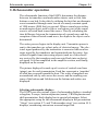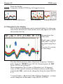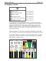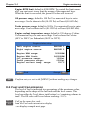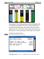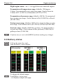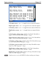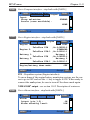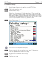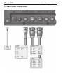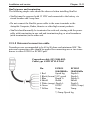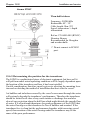
1
INSTRUCTION MANUAL
SIMRAD
EQ44-2/EQ54-2
Echosounder
183-3453-102
06134.20
English
About this manual
The technical data, information and illustrations contained in this publication
were to the best of our knowledge correct at the time of going to print.
We reserve the right to change specifications, equipment, installation and
maintenance instructions without notice as part of our policy of continuous
development and improvement. No part of this publication may be reproduced,
stored in a retrieval system or transmitted in any form, electronic or otherwise
without prior permission from Simrad AS. No liability can be accepted for
any inaccuracies or omissions in the publication, although every care has been
taken to make it as complete and accurate as possible.
This manual combines operating and installation information for the EQ44-2
and EQ54-2 Echosounder. We recommend that you familiarise yourself with
the basic instructions prior to installation or use.
EQ44-2/EQ54-2 Echosounder
Table of contents
Chapter 1 Introduction and safety summary
1.1
Introduction and system familiarization .......................................1-1
1.2
Safety summary ........................................................................... 1-2
1.3
How to get started .........................................................................1-3
1.3.1
Dedicated function keys ............................................................... 1-4
1.3.2
Echosounder features ................................................................... 1-5
Chapter 2 Fundamentals and initial startup
2.1
Fundamentals of the display and page system ............................. 2-1
2.1.1
Example of how to exchange a page in the PAGE system ........... 2-2
2.1.2
Example of how to select a new display in a custom screen ........ 2-2
2.2
Key functions ............................................................................... 2-3
2.3
Menu bar ....................................................................................... 2-5
2.4
Menu layout .................................................................................. 2-6
2.5
Initial start-up ............................................................................... 2-7
2.6
Turn power on............................................................................... 2-8
2.7
Turn power off .............................................................................. 2-8
2.8
Simrad WR20 RemoteCommander (optional) ............................. 2-8
Chapter 3 Echosounder operation
3.
Echosounder operation ................................................................. 3-1
3.1
Parts of an echosounder................................................................ 3-2
3.2
How the echosounder works......................................................... 3-3
3.3
Transducer beam width ................................................................3-4
3.4
Effects of the vessel’s speed ......................................................... 3-5
Chapter 4 STND menu
4.1
STND menu.................................................................................. 4-1
4.2
Shortcut to the pages in the STND echo-series ........................... 4-1
4.3
Standard echo display................................................................... 4-2
4.4
Variable range marker .................................................................. 4-3
4.5
Echo quick menu ..........................................................................4-4
4.6
Plot event mark on echo display ...................................................4-4
4.7
Presentation setup......................................................................... 4-5
Chapter 5 B-LCK menu
5.1
B-LCK menu ................................................................................ 5-1
Table of contents
EQ44-2/EQ54-2 Echosounder
Chapter 6 ZOOM menu
6.1
ZOOM menu................................................................................. 6-1
Chapter 7 SHIFT menu
7.1
SHIFT menu ................................................................................. 7-1
Chapter 8 PILOT menu
8.
PILOT menu ................................................................................. 8-1
8.1
Highway display ........................................................................... 8-1
8.1.1
Navigation setup ........................................................................... 8-1
8.2
Position display ............................................................................. 8-3
Chapter 9 Engine monitoring
9.
Engine menu ................................................................................. 9-1
9.1
Engine status ................................................................................ 9-3
9.2
Fuel and transmission ...................................................................9-4
9.3
Battery status ................................................................................ 9-6
9.4
Second set of engine monitoring displays .................................... 9-8
9.5
Demo mode .................................................................................. 9-8
Chapter 10 Miscellaneous menu
10.
Miscellaneous menu ................................................................... 10-1
10.1
Decca lanes ................................................................................. 10-1
10.2
Loran C ....................................................................................... 10-3
10.3
Depth & temperature diagram ................................................... 10-5
Chapter 11 Setup menu
11.
Setup menu ..................................................................................11-1
11.1
Echosounder setup.......................................................................11-1
11.2
Pilot/Position setup ..................................................................... 11-4
11.3
Speed alarm, units & language ...................................................11-5
11.4
Interface setup .............................................................................11-7
11.4.1 Description of NMEA0183 sentences ....................................... 11-13
11.4.2 Description of NMEA2000 sentences ...................................... 11-14
11.5
Palette setup............................................................................... 11-15
11.6
Factory settings ......................................................................... 11-16
11.7
QuickGuide ............................................................................... 11-18
EQ44-2/EQ54-2 Echosounder
Table of contents
Chapter 12 Installation and service
12.
Installation and service............................................................... 12-1
12.1
Installation notes ........................................................................ 12-1
12.2
Installation of EQ44-2 ................................................................ 12-3
12.3
Installation of EQ54-2 ................................................................ 12-5
12.4
Location for display unit ............................................................ 12-7
12.5
Electrical connections ................................................................ 12-8
12.5.1 Power supply connections .........................................................12-10
12.5.2 Fuse............................................................................................12-10
12.5.3 Transducer connection ..............................................................12-10
12.5.4 Interface connection ..................................................................12-12
12.5.5 Universal connection cable........................................................12-13
12.6
Basic transducer and cable information ....................................12-14
12.6.1 Transducers (optional) ...............................................................12-15
12.6.2 Determining the position for the transducer .............................12-18
12.7
Preventive maintenance............................................................ 12-20
12.8
Repair and service .................................................................... 12-20
12.9
Troubleshooting .........................................................................12-21
12.10
Specifications ........................................................................... 12-22
Appendix A Glossary of terms ...................................................................A-1
Index
.............................................................................. end of manual
CE Declaration .......................................................................... end of manual
International warranty .............................................................. end of manual
List of Simrad distributors ........................................................ end of manual
Table of contents
EQ44-2/EQ54-2 Echosounder
Introduction and safety summary
Chapter 1-1
1.1 Introduction and system familiarization
Congratulations on your purchase of SIMRAD EQ44-2/EQ54-2 Echosounder and Fishfinder - a high performance echosounder in a unique slimline design with a bright 10” (EQ44-2) or 15” (EQ54-2) TFT color display.
The EQ44-2/EQ54-2 is both an echosounder system with selectable frequency
i.e. 38, 50 or 200 kHz, providing an impression of what is to be found in the
water under the vessel, and it is a repeater for navigational data from connected GPS receiver.
The SimNet data and control network provides high speed data transfer and
control between Simrad products that are integrated as a total navigation,
steering and communication system on board.
How to use this manual?
This manual is written for the products: EQ44-2 and EQ54-2, which share the
same type of software. From hereon, these models are referred to as: EQXX.
It is a good idea if you make yourself familiar with the key functions, menu
structure and rotation of pages (screens) described in chapter 2 before you
start out, and then proceed with section 2.5 Initial start-up. For quick location
of a certain term, please check the “Glossary of terms” and the “Index” at the
back of the manual. Also, “How to get started” further on in this chapter will
give you a quick introduction to some of the features you have access to in
your new echosounder.
The display examples shown in this manual are not always an exact copy of
what you will see on the screen, as the presentation depends on your system
configuration and choices of setup.
How to interpret special marked key symbols etc. in the manual:
+/-
Either the + (plus) or - (minus) key may be applied.
0-9
Alpha-numeric keys for insertion of figures.
A-Z
Alpha-numeric keys for insertion of letters.
)
1,3
Emphasizes important points.
Indicates that you should press the keys [1] and [3] to obtain what is
written in italic next to the key.
Chapter 1-2
Introduction and safety summary
1.2 Safety summary
Precaution: Do not open the equipment, only qualified persons should work
inside the equipment. If the glass in the screen breaks, be careful not to get cut
on the sharp edges of the glass pieces.
) The lifetime of the internal battery is minimum 5 years. If not exchanged
before it goes flat, all data in the unit’s memory will be lost. We strongly
recommend that you have the battery exchanged at your local Simrad workshop max. 5 years from date of purchase.
Power source, fuse and power cable: Check that the DC power supplied to
the unit is within the range of 10 to 32 volts. Note that the appropriate fuse
must be employed (see the fuse rating in section 12.10 Specifications). Ensure
that the power cord is firmly attached.
Grounding: To reduce electrical interference and risk of electrical shock,
properly ground the unit to the ship’s ground using the ground screw at the
rear of the unit. Good grounding should also be exercised for any equipment
connected to the EQXX.
Quality service personnel: The EQXX is sealed and does not contain any
user serviceable parts. Opening of the unit will void its warranty. Touching electrical parts inside may cause bodily harm. If the unit is not working
properly, check sections 12.7 Preventive maintenance, 12.8 Repair and service,
and 12.9 Troubleshooting. If your EQXX requires servicing or repair, call your
authorized SIMRAD dealer.
Cleaning: Do not use any kind of strong solvents e.g. spirit, alcohol, gasoline or oils.
Glossary of terms: If you have never used an echosounder before or if you are
unsure of how a term is used in this manual, then turn to Appendix A - Glossary of terms.
Default settings: All user implemented data in the EQXX can be erased by
making a reset of the unit and thus return to factory default settings.
Software: The software version of the EQXX (see start-up display) should
always be informed in a service situation.
Introduction and safety summary
Chapter 1-3
1.3 How to get started
When starting up for the very first time, the first time after loading
a new software or after a master reset: Make sure that all hardware
installation and electrical connections are completed in accordance
to the installation instructions.
PWR
Press and hold the [PWR] key until you have a picture on the screen
The system will perform a software update and check for communication activity. When finished, a new start-up window will be
presented on the screen:
Automatic input source setup
Interface has not been set up!
∆
To start automatic input
source setup, make sure that
all connected products are
turned ON, and press ENT.
∆
Start
ENT
After making sure that all connected products are turned ON:
ENT
Press [ENT] to start automatic input source setup, - if a new product
is connected later on, refer to section 11.4 Interface setup.
New window: Automatic input source setup listing Data type, Group
and Source of connected units.
ENT
PAGE
ENT
Press [ENT] to continue
Press [PAGE] to scroll through a quick guide which informs of the
use of the keys and where you can enter owner’s setup, etc.
- the quick guide is also accessible via [MENU], [8], [6].
Press [ENT] when ready to assume normal operation
- go to [MENU], [8], [3] if you wish to make adjustments to the
interface setup.
Chapter 1-4
)
Introduction and safety summary
To call up an echo display will require that the connected transducer
type has been selected in the Echosounder setup - [MENU],[8],[STND].
1.3.1 Dedicated function keys
STND
Press [STND] to call up the standard echo display.
Long press will toggle between echo, dual frequency, and custom
screens.
B-LCK
Press [B-LCK] to call up the bottom lock display.
Long press will toggle between echo, dual frequency, and custom
screens.
ZOOM
Press [ZOOM] to call up the zoom display.
Long press will toggle between echo, dual frequency, and custom
screens.
SHIFT
Press [SHIFT] to call up the shift display.
Long press will toggle between echo, dual frequency, and custom
screens.
PAGE
Press the [PAGE] key to toggle between the current active pages
under the main function keys. Press for two seconds to start automatic rotation of these pages. Press any key to return to normal
operation.
Introduction and safety summary
Chapter 1-5
1.3.2 Echosounder features
A-scope - Press [ENT], [2] to toggle A-scope on/off. Echoes are displayed in a
‘bar-graph’ format. The strength of the actual echo is indicated by both width
and color intensity.
Change frequency - Press [ENT], [1] to toggle between e.g. 50 and 200 kHz.
Gain - Adjust gain with the [GAIN-] and [GAIN+] keys to just below the
point where you begin to see speckles of ‘noise’ on the screen.
Range - Select range by the numeric keys 1-9, or adjust with the +/- keys.
Key 0 will select Auto Range.
Bottom expansion* - Press [B-LCK] to call up the bottom lock display.
Activate bottom expansion to expand the view of the bottom in the
echosounder display.
VRM expansion* - Press [ZOOM] to call up the zoom display. Activate
VRM expansion to expand the view near the VRM - Variable Range Marker
- in the echosounder display. Use the up/down cursor to activate and move the
VRM line.
Shift display* - Press [SHIFT] to call up the shift display when operating
in deep waters. Select the range for an expansion window. The expansion
window can automatically follow a changing bottom or be set manually by the
+/- keys.
*Return to standard echosounder display by pressing [STND].
Echo setup (presentation) - Press [ADJ] from echo display to access the setup
display for either 38, 50 or 200 kHz. Press [ENT] to confirm changes, or leave
the setup without having made any changes by pressing [MENU].
Echosounder setup - Press [MENU], [8], [STND] when you need to make
any general settings, selecting a transducer or selecting demo mode etc.
Transmit power off - Press [ENT], [STND] to stop transmission in order to
observe noise picked up by the transducer or to reduce power consumption.
Chapter 1-6
Introduction and safety summary
Fundamentals & initial start-up
Chapter 2-1
2.1 Fundamentals of the display and page system
The EQ44-2/EQ54-2 Echosounder has a multi-function screen and
data presentation system with full screen and different types of split
screens. The series of pages under the function keys (situated in the
left column of the keypad) will in most situations be sufficient information for the operator.
In split screens consisting of up to four displays, the active display
is indicated by a solid red frame. Use the [WIN] key to clockwise
toggle between which display on the screen is active. Only active
displays are operable.
The [PAGE] key differs from the other function keys. There are four
pages under the [PAGE] key which can be set up to the presentation
you prefer by exchanging an existing display in the PAGE system
with a new one selected from a function key or via the menu - see
next page. Single press on the [PAGE] key will toggle between the
active pages under the function keys e.g.:
STND display
B-LCK display
ZOOM display
SHIFT display
Chapter 2-2
Fundamentals & initial start-up
Long press on the [PAGE] key will start
a rotation of the four pages in intervals of
5 seconds (increase/decrease the time in
[MENU], [8], [2]). Press any key to stop
rotation.
2.1.1 Example of how to exchange a page in the PAGE system
The four pages in the PAGE system are collected from the STND,
B-LCK, ZOOM and SHIFT menus in the sequence of which the
function keys appear on the keypad ie. the first page is from the
STND function, the second page is from the B-LCK function, the
third page is from the ZOOM function, and the fourth page is from
the SHIFT function. This sequence can not be changed, only the
choice of display collected from each function can be changed e.g.:
PAGE
Press the [PAGE] key until the full screen standard display appears
MENU
Call up the menu bar, and...
1,3
collect the Dual frequency display
- or you can toggle between the available displays in the STND function by pressing (long press) the [STND] key repeatedly.
The same applies for the other three pages in the PAGE system ie.
press the [PAGE] key until a display from the B-LCK, ZOOM or
SHIFT function appears and then collect a new display from the
appropriate menu.
)
The display sequence under the function keys is the same as the
display sequence in the matching menu.
2.1.2 Example of how to select a new display in a custom screen
In custom screens with multiple window combinations, all displays, which are not main function displays, are exchangeable. It is
also possible to change the right half of the screen from half screen
window to two quarter windows and vice versa. Example:
MENU
Call up the menu bar, and...
Fundamentals & initial start-up
Chapter 2-3
Highlight a function e.g. Depth & temperature diagram in the MISC
menu.
WIN
Press [WIN] several times to check the screen image (situated to the
far right in the top line of the menu bar) which windows the function
can be placed into
ENT
Press [ENT] to enter the highlighted function into the highlighted
window
)
If the function text in the menu is red, the display will not be available for the selected window.
2.2 Key functions
Some of the key functions are general and can be applied at any
time, other key functions are related to a certain menu(s) and can
only be applied when in the appropriate menu.
EVENT
Inserts a vertical mark at current ping and sends out WPL via NMEA
to connected chartplotter.
MENU
Turns the menu bar on/off. Exits any data display without taking any
action.
ENT
Confirms insertion and editing of data. Calls up quick menu.
Moves cursor in data displays. Moves left/right/up/down in the menu
system. Adjusts gain (left/right). Activates and moves VRM (up/
down) in echo display.
+/-
Changes echosounder range i.e. + (plus) for larger range and (minus) for smaller range. Toggles between available values.
GAIN
Adjusts echosounder gain. Optimum adjustment: Press [GAIN+] till
noise appears in ‘water’, then press [GAIN-] till noise just disappears
again.
STND
Shortcut to standard echo displays. Long press will toggle between
standard echo display in full screen, Dual frequency, and two
custom screens.
Chapter 2-4
Fundamentals & initial start-up
B-LCK
Shortcut to bottom lock displays. Long press will toggle between
bottom lock display in full screen, Dual frequency, and two custom
screens.
ZOOM
Shortcut to zoom display. Long press will toggle between zoom display in full screen, Dual frequency, and two custom screens.
SHIFT
Shortcut to shift display. Long press will toggle between shift display in full screen, Dual frequency, and two custom screens.
PAGE
Toggles between active pages under the four main function keys i.e.
[STND], [B-LCK], [ZOOM] and [SHIFT]. Long press starts automatic rotation of these pages. Press any key to stop rotation.
ADJ
Gives access to setup displays related to active display. Scrolls
through adjustable parameters.
VRM
Toggles VRM - Variable Range Marker - on/off.
WIN
Toggles between active windows in split screen. The active window
will have a solid red frame. Only active windows are operable.
0-9
The alphanumeric keys inserts and selects data in data displays.
Keys 1-9 are also Quick-range keys, which each represent a fixed
echosounder range. Key 0 will activate auto range.
CLR
Turns off VRM line in active display. Deletes data in enter or edit
mode.
PWR
Power on - hold key depressed till you have a picture on the screen.
Calls up a window where you can adjust the brightness in the screen,
background light in keypad, and select Daylight displays, Night
display or custom made color palettes. Hold two seconds to turn the
power off.
Fundamentals & initial start-up
Chapter 2-5
2.3 Menu bar
MENU
Toggles the menu bar on/off
To fit the complete menu bar across the screen, some of the menus
have been abbreviated. However, the last selected menu will be highlighted, and if it’s an abbreviation of the menu, then the complete
menu title is written above the menu bar.
PILOT
1
STND
WIN
2
3
B-LCK ZOOM
4
5
6
7
8
SHIFT
PILOT
ENG
MISC
SETUP
1
Highway
2
Position
Having selected e.g. 5:PILOT from the menu bar, its associated menus will
drop down. Key in the number next to the function you wish to call forward,
or use the cursor key to highlight the function and press [ENT].
If you want to switch to a different menu, use the cursor key left/right to move
to the adjacent menu.
Most functions in the menus are general, and can be called forward at any
time. Functions not currently available will have a different color from the rest
of the functions. Not all functions are available in any window size i.e. full
screen, half screen or quarter window. Use the [WIN] key to toggle between
the windows in which the highlighted function can be presented. Keep an eye
on the functions in the menu to see how they may change color as you toggle
from window to window.
The menu bar will disappear from the screen at the selection of a function, or
by pressing the [MENU] key. Besides, if not used, it automatically turns off
after 30 seconds.
Chapter 2-6
Fundamentals & initial start-up
2.4 Menu layout
1
2
3
STND
B-LCK
ZOOM
1 50kHz
1 50kHz
1 50kHz
2 200kHz
2 200kHz
2 200kHz
3 Dual frequency
3 Dual frequency
3 Dual frequency
4 Custom screen 1
4 Custom screen 1
4 Custom screen 1
5 Custom screen 2
5 Custom screen 2
5 Custom screen 2
4
5
6
SHIFT
PILOT
ENG
1 50kHz
1 Highway
1 Engine status
2 200kHz
2 Position
2 Fuel and transmission
3 Dual frequency
3 Batteri status
4 Custom screen 1
4 2nd Engine status
5 Custom screen 2
5 2nd Fuel and transmission
6 2nd Batteri status
7
8
MISC
SETUP
1 Decca lanes
STND Echosounder setup
2 Loran C
1 Pilot/Position setup
3 Depth & temperature diagram
2 Speed alarm, units & language
3 Interface setup
4 Palette setup
5 Factory settings
6 QuickGuide
When selecting a sub-menu in the SETUP menu, the display will always
appear in a pop-up window, so once you have accepted the changes or decided
to just exit the display, then the display will disappear from the screen.
Fundamentals & initial start-up
Chapter 2-7
2.5 Initial start-up
When starting up for the very first time, the first time after loading
a new software or after a master reset: Make sure that all hardware
installation and electrical connections are completed in accordance
to the installation instructions.
PWR
Press and hold the [PWR] key until you have a picture on the screen
The system will perform a software update and check for communication activity. When finished, a new start-up window will be
presented on the screen:
Automatic input source setup
Interface has not been set up!
∆
To start automatic input
source setup, make sure that
all connected products are
turned ON, and press ENT.
∆
Start
ENT
After making sure that all connected products are turned ON:
ENT
Press [ENT] to start automatic input source setup, - if a new product
is connected later on, refer to section 11.4 Interface setup.
New window: Automatic input source setup listing Data type, Group
and Source of connected units.
ENT
PAGE
ENT
Press [ENT] to continue
Press [PAGE] to scroll through a quick guide which informs of the
use of the keys and where you can enter owner’s setup, etc.
- the quick guide is also accessible via [MENU], [8], [6].
Press [ENT] when ready to assume normal operation
- go to [MENU], [8], [3] if you wish to make adjustments to the
interface setup.
Chapter 2-8
Fundamentals & initial start-up
PWR
Press [PWR] again to adjust the lighting in the screen and select day
or night display etc., move around in display by means of the cursor
key and change settings with +/- keys, and...
ENT
Confirm with [ENT]
Customizing the EQXX to suit individual needs can be done as you
go along i.e. choose a different color for the display background,
text, menu, etc. But to start out it will be wise to select the display
language you prefer to use:
MENU
8,2
Call up the menu bar, and...
press [8], [2] to call up the language display
Press up on the cursor to go to the bottom line in the display
+/-
Select language
ENT
Confirm entry
)
To call up an echo display will require that the connected transducer
type has been selected in the Echosounder setup - [MENU],[8],[STND].
2.6 Turn power on
Starting up for the first time, or after loading a new software, or
after a master reset - see section 2.5. Starting up at any other time:
PWR
To turn on the EQXX, press and hold the [PWR] key until you have a
picture on the screen
ENT
Press [ENT] when the system is ready
2.7 Turn power off
PWR
Call up INFO window, and...
PWR
Press and hold until screen turns black
The EQXX is now turned off. All the data and setups are saved and
stored in the internal memory and, of course, will be available next
time the unit is turned on.
Fundamentals & initial start-up
2.8 Simrad WR20 Remote Commander (optional)
Chapter 2-9
The WR20 is the first remote control that can both display and control the electronics on board when connected to the SimNet system.
You can remotely command your NavStation with full MOB control
from anywhere within a range of 100 m. You will have seamless
control of pilot and navigation. You can make VHF calls from the
WR20 and much, much more.
The new WR20 - your perfect helmsman
• Small rugged waterproof handset
• Display size: 35x25mm (1.4”x1.0”)
• Weight: 150 g
• Bluetooth Class 1
• Rechargable Li-Ion battery
• Backlit keypad
• Keypad lock
• Handy neck strap
• Environment: -10 to +55°C (-14 to +131°F)
• Dimensions H:133mm (5.2”), W:55mm (2.2”),
D:32mm (1.3”)
Chapter 2-10
Fundamentals & initial start-up
Echosounder operation
Chapter 3-1
3. Echosounder operation
The echosounder function of the EQXX determines the distance
between its transducer and underwater objects such as fish, lake
bottom or sea bed. It does this by utilizing the fact that an ultrasonic
wave transmitted through water travels at a nearly constant speed
of 1500 meters (4800 feet) per second. When a sound wave strikes
an underwater object such as fish or sea bottom, part of the sound
wave is reflected back toward the source. Thus by calculating the
time difference between the transmission of a sound wave and the
reception of the reflected sound wave, the depth to the object can be
determined.
The entire process begins in the display unit. Transmitter power is
sent to the transducer as a short pulse of electrical energy. The electrical signal produced by the transmitter is converted into an ultrasonic signal by the transducer and transmitted into the water. Any
reflected signals from intervening objects (such as a fish school)
are received by the transducer and converted back into an electrical signal. It is then amplified in the amplifier section, and finally,
displayed on the screen.
The picture displayed is made up of a series of vertical scan lines
(pings), one for each transmission. Each line represents a ‘snapshot’
of what has occurred beneath the boat. The series of snapshots are
accumulated side by side across the screen, and the resulting contours of the bottom and fish between the bottom and surface are
displayed.
Selecting echosounder displays
The EQXX provides various types of echosounder displays: standard
echogram, A-scope, bottom expansion (zoom), VRM expansion and
shift presentation. Each display has its special advantages. Select
the appropriate setup for the echosounder display in the presentation
“Setup” (see section 4.7), and “Echosounder setup” (see section 10.1)
displays, considering current sea area and target fish.
Chapter 3-2
Echosounder operation
3.1 Parts of an echosounder
An echosounder is composed of a display screen, processor, and transmitter/
receiver unit which in the case of the EQXX are housed in one unit.
Connected to this unit by a shielded cable is the transducer, which is mounted
horizontally on the bottom of the hull or on the transom.
The display screen presents in graphic and numerical form the information
the processor is receiving and accumulating from the transducer.
The processor is the “brain” of the echosounder. It is sealed inside the unit
which protects it from harm. The processor is composed of highly sophisticated microprocessor, memory and logic circuitry.
The transmitter/receiver (often called the “transceiver”) section of your
echosounder takes it’s commands from the processor. The processor tells the
transceiver to activate the transmitter. The transmitter sends a high voltage
transmit “ping” to the transducer mounted on the hull. At that point the transmitter’s job is done and the receiver takes over (see fig.1 in section 3.2).
The receiver is also connected to the transducer and amplifies the very small
signals received as echoes from fish and the sea floor which arrive at the
transducer (see fig.2 in section 3.2). The receiver is designed to reject other
signals as much as possible and provide enough amplification to see even relatively small targets at long ranges.
The amplified receiver signals are then send to the processor to be shown on
the display screen.
The transducer can be single or multiple ceramic elements in a rugged housing made from reinforced plastic, bronze or stainless steel. The transducer is
attached horizontally to the bottom of the hull. It is essential that the transducer be mounted properly, as echo transmissions are radiated at right angles
from the transducer face. Shielded cables connect the transducer with the
echosounder.
Echosounder operation
Chapter 3-3
3.2 How the echosounder works
When the EQXX is turned on, a transmitter begins
to send electrical pulses to the transducer. The
ceramic resonator in the transducer has a special
property which enables it to change dimensions
slightly when a varying voltage is applied.
The voltage is thus converted to mechanical vibrations (sound waves) which are then transmitted down
through the water.
See Fig. 1.
Fig. 1 Transmitted ‘ping’
from the transmitter/receiver.
The sound waves move through the water until they
encounter a change in density, such as a fish or the
bottom. This causes the sound waves to ‘echo’ back
up through the water. When the reflected sound
waves (echoes) hit the transducer, the ceramic disk
vibrates at the same frequency. This generates a
varying voltage which goes back up through the
cable to the receiver.
The EQXX amplifies and processes the signals and
presents them on the display screen.
See Fig. 2.
Fig. 2 The up arrow indicates:
Echo returning to the receiver.
The down arrow indicates:
Transmitted pulse.
Chapter 3-4
Echosounder operation
3.3 Transducer beam width
The transducer mounted to the hull of your vessel serves as both a ‘speaker’
when transmitting, and as a ‘microphone’ when the echosounder is receiving. Similar to the way a flashlight focuses light, most of the sound from your
transducer is focused downwards with a smaller amount going out to the sides.
The amount of focusing of the sound beam is expressed as a ‘beam width’.
Transducer
Approximation of the sound
pattern below the transducer
This angle is the transducer’s
beam width
1/2 maximum intensity
Maximum intensity
Fig. 3 A representation of a transducer beam width.
The center of the sound beam is the most intense, then as you move out
towards the sides of the sound beam there is a point where the intensity of
the sound is half what it was in the center. The distance moved is the ‘beam
width’. See Fig. 3.
Echosounder operation
Chapter 3-5
3.4 Effects of the vessel’s speed
The presentation of fish on the EQXX depends directly on the vessel’s speed,
as well as on the depth of the fish. When the vessel is at rest, the echo traces
will appear stretched and flattened. As the vessel’s speed becomes greater, the
echo traces will become shorter and more arched. The reason for this change
in appearance is that as the vessel speed increases, fewer number of sound
‘pings’ strike each fish. A low vessel speed will provide the most accurate
information of where fish are located.
Chapter 3-6
Echosounder operation
STND menu
Chapter 4-1
4.1 STND menu
1
STND
1
50kHz (38kHz)
2
200kHz
3
Dual frequency
4
Custom screen 1
5
Custom screen 2
Low and high frequency echosounder display can be set up separately. The low frequency display will show deep water bottom
contours, and the high frequency display will show the mid-water
section with trawl targets or bait fish in a higher resolution.
The Dual frequency display will provide both the 50kHz and the
200kHz echo displays in one screen.
The two custom screens will present multiple window combinations
(section 4.2), where one of the main echo displays i.e. 50kHz or
200kHz will be fixed in the left half of the screen. Adjustments can
be made individually to both displays (section 4.7).
MENU
1,2
To access one of the displays via the menu e.g.:
Call up the menu bar, and...
press [1] and [2] to call up the standard echo display for 200kHz in
full screen - see display example on next page.
4.2 Shortcut to the pages in the STND echo-series
The STND function is one of the main functions in the EQXX. Each
page under the [STND] key will include a window representing the
standard echo function. It is not possible to exchange main function
displays with a new display. Refer to section 2.1, 2.1.1 and 2.1.2 for
further information on the display and page system.
Chapter 4-2
STND
STND menu
From any display:
Long press on the [STND] key will toggle between:
38/50kHz or 200kHz full screen
Dual frequency
Custom screen 1+2
4.3 Standard echo display
This is the basic presentation mode (standard display) for observing
fish schools and sea bed. Some surface noise may appear just below
the transmission line.
Transmission line.
Time scale.
Depth range is adjustable with +/- keys or
the Quick-range keys
1-9.
Press key 0 to return
to Auto range.
The data field is preset to show: Gain level, Frequency, Transmit
pulse length A- SHORT (set to AUTO), Transmit power A- 10W
(set to AUTO), see section 4.7.
Water temperature T in Celcius or Fahrenheit (in 1/10 degrees),
water or SOG speed S in knots or kilometers/hour or miles/hour,
actual depth *DK - units can be changed in Setup for units (MENU,
8, 2).
*) Actual depth i.e. Depth below Keel/Surface/Transducer - settings
can be changed in Echosounder setup (MENU,8,STND).
STND menu
1-9
Select range in 9 steps
+/-
Adjust range with the + and - keys
0
Chapter 4-3
Activate Auto range
Press cursor left/right to adjust gain
ADJ
Direct access to Setup display related to active echo display 50kHz
or 200kHz - (see section 4.7)
Use the cursor to go to the function you wish to change the value for
+/-
Toggle between available values
ENT
Confirm changes, or...
MENU
Abandon changes and exit Setup display
4.4 Variable range marker
VRM – Variable Range Marker – refers to a horizontal black line
shown on the display screen. The user can measure the range to
targets shown on the display screen by use of the VRM. The depth
to the VRM can be seen in the top left side of the screen for a few
seconds after the VRM line is moved.
From active echo display:
Activate the Variable Range Marker function, and...
Move the VRM up/down
+/CLR
)
Adjust the range by means of the +/- keys
Turn VRM off again
The VRM line can also be toggled on/off by the [VRM] key.
Chapter 4-4
STND menu
4.5 Echo quick menu
A number of echo features can easily be accessed from the Echo
quick menu.
ENT
From active echo display:
Call up the Echo quick menu with access to the following features:
Echo quick menu
1
Change frequency
2
Hide A-scope
STND
Transmit power off
MENU
Exit
1
Change frequency will toggle between 38, 50 or 200kHz displays
(Airmar transducers) to suit the task.
200 kHz is for general purpose and offers optimum discrimination
and a narrow transmitter beam.
38 and 50 kHz are for searching in a wider area, determining bottom
conditions and going the deepest.
2
Hide/Activate A-scope The amplitude scope at the right side of the
echo display indicates the precise amplitude or strength of the last
received ping (sounding), which often can be used for determining
individual species of fish or hardness of the bottom. Pressing [2]
from the quick menu will toggle between Activate or Hide A-scope.
STND
Transmit power off will stop transmission in order to observe noise
picked up by the transducer.
MENU
Abandon the Echo quick menu without making any changes
4.6 Plot event mark on echo display
From active echo display:
EVENT
Inserts a vertical mark at current ping and sends out WPL via
NMEA to connected chartplotter.
STND menu
Chapter 4-5
4.7 Presentation setup
The general Echosounder setup e.g. Selecting transducer, Alarm settings, Demo mode etc. is placed in the SETUP menu (section 10.1).
The echo setup in this chapter are the most common settings for
adjusting the presentation of the high or low frequency echo picture,
and can be accessed by a single keystroke.
ADJ
Press [ADJ] from active echo display
Setup
200kHz:
Range start:
000 m
Range:
AUTO
25 m
Gain:
052%
White line:
OFF
Expansion window:
6 m
TVG:
Normal (20 log R)
Ping to ping filter:
ON
Signal threshold:
OFF
Color threshold:
OFF
Depth grid:
OFF
Transmit pulse length:
AUTO
Transmit power:
AUTO
Scroll synchronization:
TIME
Scroll speed:
HIGH
Use the cursor key to move cursor around in the display
0-9
Key in new figures, or...
+/-
Toggle between available values
ENT
Confirm changes, or...
MENU
Abandon changes and exit display
Range start – allows the user to set the displayed depth range to
begin at some point below the surface. For example, a 100 meter displayed range can be “phased” downwards, so that the screen shows
a 100 meter section beginning at, say, 200 meters and going to 300
meters depth.
Chapter 4-6
STND menu
Range – refers to the distance shown from the top to the bottom of
the display screen. Selecting Auto range will cause the EQXX to
change the basic range setting(s) to keep the displayed bottom in
the lower half of the display. For instance, as your boat moves into
deeper waters, the system will automatically switch to a deeper
range, always keeping the displayed bottom in the lower half of the
display. Manual range allows the operator to set the range displayed
on the screen.
Gain – is another way of saying “sensitivity”, or possibly “volume”.
Increasing the gain setting of the EQXX will allow you to see
smaller and deeper targets. If the gain is set too high, however, you
will begin to see “noise” and unwanted targets. Generally speaking,
you want to set the gain control just below the point that you begin
to see speckles of “noise” between surface and the bottom on the
screen.
White line – is a control which places a white/black line at the
displayed sea floor and blanks out 4 pixels just below the line. The
purpose of this is to help the user detect targets, such as fish, which
are very close to the sea floor and whose echoes tend to merge with
those of the sea floor itself.
Expansion window (zoom level) - can be selected in eight steps,
ranging from 1 to 50 meters, or converted to feet or fathoms (refer
to Setup for units, section 11.3). This function allows you to take a
closer look at a particular section of the water underneath your boat.
You can expand the view near the bottom (Bottom expansion) or
near the Variable Range Marker (VRM expansion).
TVG – Time Varying Gain – is a control that allows the EQXX to
make corrections for most of the losses and absorption that occurs as
sound energy passes through sea water. There are three settings to
choose from, Normal, Special and OFF.
The setting “Normal (20 log R)” is for general fish finding at depths
down to 50m (150’) and it will also give a uniform bottom echo presentation at shallow, mid and deep water.
The setting “Special (40 log R)” will adjust the TVG to show the
same echo strength for a given size fish at varying depths.
The OFF position is used for net sounders. In OFF position the TVG
is inactive which means that the sounder operates with a fixed gain
between each transmitter pulse. Auto range is switched to manual.
STND menu
Chapter 4-7
Ping to ping filter – can be set to either on or off. With the filter
“off”, then each received echo will be reflected on the screen.
Whereas with the filter “ON”, the system will compare every two
echoes received and only reflect on the screen what is received from
both echoes, which will give a more uncluttered recording.
Signal threshold – can be set to ON to eliminate the appearance
of unwanted noise. The threshold level is automatic and the feature
should be used with caution, as it may eliminate small fish and small
unidentified objects on the screen.
Color threshold – the color threshold function allows the “weaker”
targets and noise which may be shown on the display screen to be
eliminated from the display. These targets are usually shown in the
weaker target colors such as blues and greens. The Color threshold allows you to choose not to display the blues, or the blues and
greens, etc. Doing this will leave only the stronger targets on the
display screen.
Depth grid - enables a more precise reading of depth and target relations across the screen.
Transmit pulse length – can be set OFF to observe noise in the
water (Auto range will switch to manual mode). Set to AUTO, the
optimum setting will be applied according to the water depth. Or it
can be set manually, if a specific pulse length is required:
SHORT
MEDIUM
LONG
less than 10m deep water
between 10 and 50 m deep water
more than 50m deep water
) A long pulse will reach deeper but give less resolution.
Transmit power – should normally be left on AUTOmatic.
The modes available are: AUTO, 1000W, 500W, 100W and 10W.
When operating above 100W, the ping rate will be max. 10 pings per
second. Operating at 100W or 10W will enable a ping rate of up to
25 pings per second.
Scroll synchronization – the screen can be updated on the basis of
time or distance (when data from last ping appears on the display).
Chapter 4-8
STND menu
Scroll speed – is the ping rate and movement of the presentation of
echoes on the screen, moving from right to left. It is adjustable (Low,
Medium, High, Max, Freeze), to allow the user to show a longer
“history” on the display screen, if desired.
B-LCK menu
Chapter 5-1
5.1 B-LCK menu
2
B-LCK
1
50kHz (38kHz)
2
200kHz
3
Dual frequency
4
Custom screen 1
5
Custom screen 2
Low and high frequency echosounder display can be set up separately. The low frequency display will show deep water bottom
contours, and the high frequency display will show the mid-water
section with trawl targets or bait fish in a higher resolution.
The Dual frequency display will provide both the 50kHz and the
200kHz echo displays in one screen.
The two custom screens will present multiple window combinations
(section 4.2), where one of the main echo displays i.e. 50kHz or
200kHz will be fixed in the left half of the screen. Adjustments can
be made individually to both displays (section 4.7).
Shortcut to the pages in the B-LCK echo-series
The B-LCK function is one of the main functions in the EQXX.
Each page under the [B-LCK] key will include a window representing the bottom lock function. It is not possible to exchange main
function displays with a new display. Refer to section 2.1, 2.1.1 and
2.1.2 for further information on the display and page system.
MENU
2,2
To access one of the displays via the menu e.g.:
Call up the menu bar, and...
press [2] and [2] to call up the bottom lock display for 200kHz in full
screen - see display example on next page.
Chapter 5-2
B-LCK menu
The advanced bottom lock and expansion feature ensures a reliable depth readout and provides a compressed standard display in
the upper part of the screen. The bottom area can be magnified for
better separation of echoes. The actual size of the expansion window
can be adjusted in the presentation setup.
Transmission line.
Time scale.
Depth range is adjustable with +/- keys or
the Quick-range keys
1-9.
Press key 0 to return
to Auto range.
Press cursor left/right to adjust gain
ADJ
Direct access to presentation setup related to active echo display
50kHz or 200kHz - (see section 4.7)
Use the cursor to go to the function you wish to change the value for
+/-
Toggle between available values
ENT
Confirm changes, or...
MENU
ENT
Abandon changes and exit Setup display
Echo quick menu
Call up the Echo quick menu with access to the following features:
z Change frequency.
z Activate/hide A-scope
z Turn transmit power on/off
ZOOM menu
Chapter 6-1
6.1 ZOOM menu
3
ZOOM
1
50kHz (38kHz)
2
200kHz
3
Dual frequency
4
Custom screen 1
5
Custom screen 2
Low and high frequency echosounder display can be set up separately. The low frequency display will show deep water bottom
contours, and the high frequency display will show the mid-water
section with trawl targets or bait fish in a higher resolution.
The Dual frequency display will provide both the 50kHz and the
200kHz echo displays in one screen.
The two custom screens will present multiple window combinations
(section 4.2), where one of the main echo displays i.e. 50kHz or
200kHz will be fixed in the left half of the screen. Adjustments can
be made individually to both displays (section 4.7).
Shortcut to the pages in the ZOOM echo-series
The ZOOM function is one of the main functions in the EQXX.
Each page under the [ZOOM] key will include a window representing the zoom function. It is not possible to exchange main function
displays with a new display. Refer to section 2.1, 2.1.1 and 2.1.2 for
further information on the display and page system.
MENU
3,2
To access one of the displays via the menu e.g.:
Call up the menu bar, and...
press [3] and [2] to call up the zoom display for 200kHz in full
screen - see display example on next page.
Chapter 6-2
ZOOM menu
This feature will provide an expanded view of the area near the
*VRM line which will give a better separation of echoes. The actual
size of the expansion window can be adjusted in the presentation
setup.
*) See section 4.4 Variable range marker.
Transmission line.
Time scale.
Depth range is adjustable with +/- keys or
the Quick-range keys
1-9.
Press key 0 to return
to Auto range.
Press cursor left/right to adjust gain
ADJ
Direct access to presentation setup related to active echo display
50kHz or 200kHz - (see section 4.7)
Use the cursor to go to the function you wish to change the value for
+/-
Toggle between available values
ENT
Confirm changes, or...
MENU
ENT
Abandon changes and exit Setup display
Echo quick menu
Call up the Echo quick menu with access to the following features:
z Change frequency.
z Activate/hide A-scope
z Turn transmit power on/off
SHIFT menu
Chapter 7-1
7.1 SHIFT menu
4
SHIFT
1
50kHz (38kHz)
2
200kHz
3
Dual frequency
4
Custom screen 1
5
Custom screen 2
Low and high frequency echosounder display can be set up separately. The low frequency display will show deep water bottom
contours, and the high frequency display will show the mid-water
section with trawl targets or bait fish in a higher resolution.
The Dual frequency display will provide both the 50kHz and the
200kHz echo displays in one screen.
The two custom screens will present multiple window combinations
(section 4.2), where one of the main echo displays i.e. 50kHz or
200kHz will be fixed in the left half of the screen. Adjustments can
be made individually to both displays (section 4.7).
Shortcut to the pages in the SHIFT echo-series
The SHIFT function is one of the main functions in the EQXX. Each
page under the [SHIFT] key will include a window representing the
shift function. It is not possible to exchange main function displays
with a new display. Refer to section 2.1, 2.1.1 and 2.1.2 for further
information on the display and page system.
MENU
4,2
To access one of the displays via the menu e.g.:
Call up the menu bar, and...
press [4] and [2] to call up the shift display for 200kHz in full screen
- see display example on next page.
Chapter 7-2
SHIFT menu
This feature can be applied when operating in deep waters. The
expansion window can automatically follow a changing bottom or
be set manually by means of the numeric keys 1-9, and then use the
+/- keys or cursor to move the window up/down.
Press the [0] key for automatic bottom tracking.
Transmission line.
Time scale.
Press cursor left/right to adjust gain
ADJ
Direct access to presentation setup related to active echo display
50kHz or 200kHz - (see section 4.7)
Use the cursor to go to the function you wish to change the value for
+/-
Toggle between available values
ENT
Confirm changes, or...
MENU
ENT
Abandon changes and exit Setup display
Echo quick menu
Call up the Echo quick menu with access to the following features:
z Change frequency.
z Activate/hide A-scope
z Turn transmit power on/off
PILOT menu
Chapter 8-1
8. PILOT menu
5
PILOT
1
Highway
2
Position
8.1 Highway display
To present any information in the EQXX highway display will
require that a navigator is connected via SimNet or the NMEA input
port - refer to section 12.5 Electrical connections.
) The connected navigator must be in navigation mode, which
could be Cursor, Waypoint, Route or Track navigation - see next
page.
8.1.1 Navigation setup
MENU
5,1
Call up the menu bar, and...
load Highway display
Since there is no navigation mode active, you will receive the legend:
NAVIGATION IS OFF. To enter the basic Navigation setup:
ADJ
Load Navigation setup
Navigation setup:
XTE distance:
00.10nm
Alarm distance can be changed in this display, but alarm can only be
initiated from the connected navigator. Maximum setting in nautical
miles is 9.99 nm.
Chapter 8-2
ENT
PILOT menu
Return to Highway display
Highway display (with active navigation mode)
d
e
c
e
Nautical miles indication (0.10nm and 0.20nm) on horizontal lines
indicates how many nautical miles there are from ship’s position to
the horizontal line.
C: Course over ground
X: Cross-track-error
S: Speed over ground
B: Bearing to approaching WP
D: Distance to waypoint
V: Speed towards WP (velocity)
Bottom line indicates name/number of approaching waypoint or
routepoint.
c Ship’s position and heading in relation to intended track.
d Ideal course line between two waypoints starting from ship’s
position when a navigation mode is activated on connected navigator.
e XTE alarm lines - an alarm will sound if the ship touches the
lines (default distance: 0.10nm).
PILOT menu
Chapter 8-3
8.2 Position display
) To present a position will require that the echosounder is connected to a navigator (GPS position sensor).
MENU
5,2
Call up the menu bar, and...
load Position display
Trip log 1 and 2.
Position in three decimals in minutes.
Water speed/speed
over ground.
External POS
Course, magnetic or
true.
15-01-2006
Position update - if, for some reason, there is no position update
from external sensor, the displayed position will start to flash and
once normal position update is resumed the flashing will stop.
Position display setup
The general Position setup e.g. Display position as: LAT/LON,
Decca or Loran C, etc. is placed in the SETUP menu (section 11.2).
ADJ
From position display, press [ADJ] to load Position display setup:
Pos display setup:
Log 1:
Log 2:
Additional data:
Go to the function you wish to change
00000.0nm
00000.0nm
DEPTH
Chapter 8-4
CLR
Reset log
0-9
Key in new values, or...
+/-
Toggle between available values
ENT
Confirm editing and return to the Position display
PILOT menu
Log - reset log or insert alternative start figure by altering the value
in the “Log 1” and/or “Log 2” line. Press [CLR] to reset the figure,
and press the numeric keys 0-9 to alter the figure.
Additional data - can be set to DEPTH or COMPASS.
DEPTH will be shown from built-in echosounder.
COMPASS will show heading from connected sensor.
Engine monitoring
Chapter 9-1
9. Engine menu
5
ENG
1
Engine status
- see section 9.1
2
Fuel and transmission
- see section 9.2
3
Battery status
- see section 9.3
4
2nd Engine status
- see section 9.4
5
2nd Fuel and transmission
- see section 9.4
6
2nd Battery status
- see section 9.4
This graphical engine monitoring system is available for engines
outputting data via NMEA2000® or an appropriate interface device
supporting NMEA2000®. Depending on the engine system and
interface, some data may not be transmitted on the databus. If not
readily available, please contact the engine manufacturer or your
local Simrad dealer.
The menu points 4, 5 and 6 are a second set of displays, which only
will be visible if the system detected more than two engines on board.
The EQ44-2/EQ54-2 is capable of receiving and presenting various
engine data in either full screen or split screen with two or all three
data displays on same screen:
Chapter 9-2
Engine monitoring
For dual engines, the system provides ‘dual bar analog instruments’
to give a precise overview of the rpm synchronization and to make
direct comparison of data between the two engines.
The engine monitoring system provides analog graphical gauges and
digital (numerical readings) data for up to four engines - see display
examples further on in this chapter.
General settings
SimNet will auto detect the engines at start-up and will automatically set up the parameters in default mode. Before using the engine
monitor system, you may want to edit the setup to customize the
read-out. The top line identifies the engine/battery, the default is
ENGINE 1 to 4 or BATTERY 1 to 4. Insert the correct name for the
engine/battery in the Interface setup:
MENU
8,3
GAIN+
Call up the menu bar, and...
load the Interface setup
Use the [GAIN+] key to go to the Engine tab
Go to the name you wish to change,
- refer to section 11.5 Alphanumeric names
ENT
Confirm entry and exit
To change the measuring units, refer to ‘Setup for units’ in section
11.3.
Engine monitoring
Chapter 9-3
9.1 Engine status
MENU
6,1
Call up the menu bar, and...
load the Engine status display
Forward
Reverse (N = Neutral)
The numbers at the bottom represents Engine 1 to the left and
Engine 2 to the right in each column.
The Engine status display will provide data from 1 or 2 engines.
If there are more than 2 engines on board (and connected to the
system), a second Engine status display is available by pressing:
[MENU], [6], [4].
The default ranges in the Engine status display can be viewed and
changed as described below, except for Tilt, which is read-only
information of the exact tilt of the outboard engine in percentage, or
of the Stern drive. No range or limitation can be entered.
ADJ
To change the default settings:
Load Engine status setup
- see display example next page.
Left engine source - use +/- to toggle between connected engines.
Right engine source - use +/- to toggle between connected engines.
Engine RPM range, default is 5000 RPM. Selectable in steps from
2500 to 12500 by means of the +/- keys.
Chapter 9-4
Engine monitoring
Engine RPM limit, default is 4200 RPM. To control the limit manually, you can insert a new limit by means of the numerical keys.
When the limit is exceeded, the green fill color will turn red.
Oil pressure range, default is 100 Psi. Use numerical keys to enter
new range. Can be shown in Psi (10-125 Psi) or Pascal (69-862 kPa).
Turbo pressure range, default is 50 Psi. Use numerical keys to enter
new range. Can be shown in Psi (10-125 Psi) or Pascal (69-862 kPa).
Engine coolant temperature range, default is 120 degrees Celcius.
Use numerical keys to enter new range. Can be shown in Celcius
(40°C to 200°C) or Fahrenheit (104°F to 392°F).
Engine status setup
Left engine source:
Right engine source:
ENGINE 1 ∆
ENGINE 2
Engine RPM range:
Engine RPM limit:
Oil pressure range:
Turbo pressure range:
Engine coolant temp. range:
5000RPM
04200RPM
100Psi
050Psi
120°C
∆
MENU
ENT
Exit
Accept ENT
Confirm entry or exit with [MENU] without making any changes
9.2 Fuel and transmission
The level of fuel is indicated in a percentage of the maximum value,
depending on the shape of the fuel tank and the level sensor. This
level can either be ‘level above tank bottom’ or ‘remaining volume in
tank’. The fill color will be red when reaching < 10 %.
MENU
6,2
Call up the menu bar, and...
load the Fuel and transmission display
- see display example next page.
Engine monitoring
Chapter 9-5
In the top part of this display you have read-outs for Engine 1 to the
left and Engine 2 to the right and a total for both in the middle. The
second line in the middle i.e. ‘17.0 L/nm’ - liter per nautical mile,
is calculated by the NavStation. The read-out can be presented in
L/nm, L/km, L/mi, G/nm, G/km, G/mi. The unit can be selected in
[MENU], [8], [1], see section 10.5. The numbers at the bottom represents Engine 1 to the left and Engine 2 to the right in each column.
To change the default settings:
Load Fuel and transmission setup
Fuel and transmission setup
Left engine source:
Right engine source:
Transm. oil temp. range:
Transm. oil pressure range:
Fuel pressure range:
Fuel rate range:
ENGINE 1 ∆
ENGINE 2
120°C
0100Psi
100Psi
0030L/h
∆
ADJ
MENU
Exit
Accept ENT
Left engine source - use +/- to toggle between connected engines.
Chapter 9-6
Engine monitoring
Right engine source - use +/- to toggle between connected engines.
Transmission oil temperature range, default is 120 degrees
Celcius. Use numerical keys to enter new range. Can be shown in
Celcius (50°C to 300°C) or Fahrenheit (122°F to 572°F).
Transmission oil pressure range, default is 100 Psi. Use numerical
keys to enter new range. Can be shown in Psi (10-500 Psi) or Pascal
(69-3447 kPa).
Fuel pressure range, default is 100 Psi. Use numerical keys to enter
new range. Can be shown in Psi (10-125 Psi) or Pascal (69-862 kPa).
Fuel rate range, default is 0030 liter per hour. Use numerical keys
to enter new range. Can be shown in liter per hour (1-1000 L/h) or
gallon per hour (1-264 G/h).
ENT
Confirm entry or exit with [MENU] without making any changes
9.3 Battery status
MENU
6,3
ADJ
Call up the menu bar, and...
load the Battery status display
To change the default ranges:
Load Battery status setup
- see display example next page.
Engine monitoring
Chapter 9-7
Battery status setup
Left battery source:
Right battery source:
ENGINE 1 ∆
ENGINE 2
BATTERY 1
BATTERY 2
Left alternator volt.range:10-15 Volt
Right alternat. volt.range:10-15 Volt
Left battery voltage range:10-15 Volt
Left battery current range:
60 Amp
Right battery volt.range: 10-15 Volt
Right batt. current range:
60 Amp
MENU
Exit
∆
Left engine source:
Right engine source:
Accept ENT
Left engine source - use +/- to toggle between connected engines.
Right engine source - use +/- to toggle between connected engines.
Left battery source - use +/- to toggle between connected batteries.
Right battery source - use +/- to toggle between connected batteries.
Left alternator voltage range, default is 10-15 Volt. Selectable in
steps i.e. 10-15, 20-30 or 26-41 Volt (use +/- keys).
Right alternator voltage range, default is 10-15 Volt. Selectable in
steps i.e. 10-15, 20-30 or 26-41 Volt (use +/- keys).
Left battery voltage range, default is 10-15 Volt. Selectable in steps
i.e. 10-15, 20-30 or 26-41 Volt (use +/- keys).
Left battery current range, default is 60 Amp. Selectable in steps
from 10 to 1000 Amp (use +/- keys).
Right battery voltage range, default is 10-15 Volt. Selectable in
steps i.e. 10-15, 20-30 or 26-41 Volt (use +/- keys).
Right battery current range, default is 60 Amp. Selectable in steps
from 10 to 1000 Amp (use +/- keys).
ENT
Confirm entry or exit with [MENU] without making any changes
Chapter 9-8
Engine monitoring
9.4 Second set of engine monitoring displays
The menu points 4, 5 and 6 are a second set of displays, which only
will be visible if the system detected more than two engines on
board.
MENU
6,4
MENU
6,5
MENU
6,6
Call up the menu bar, and...
load the 2nd Engine status display
- refer to section 9.1.
Call up the menu bar, and...
load the 2nd Fuel and transmission display
- refer to section 9.2.
Call up the menu bar, and...
load the 2nd Battery status display
- refer to section 9.3.
9.5 Demo mode
For the purpose of demonstration, the engine function has a demo
mode, which can present static simulated read-outs. To run a demo
of the engine monitoring system:
MENU
8,3
GAIN+
Call up the menu bar, and...
load the Interface setup
Use the [GAIN+] key to go to the Engine tab
Go to the bottom line and toggle the demo mode on and off with +/-
ENT
Confirm entry and exit
Remember to turn off the demo mode again! The monitoring system
will not present any actual readings when the demo mode is running.
Miscellaneous menu
Chapter 10-1
10. Miscellaneous menu
7
MISC
1
Decca lanes
2
Loran C
3
Depth & temperature diagram
10.1 Decca lanes
To change the position readouts to decca mode, see section 11.2
under Pilot/Position setup, where ‘Display position as’ can be toggled to ‘Decca’.
MENU
7,1
Call up the menu bar, and...
load decca chain display
ADJ
Open for change
+/-
Leaf through the available chains - see next page.
ENT
Confirm entry
Chapter 10-2
Miscellaneous menu
List of decca chains:
00
01
02
03
04
05
06
07
08
09
10
11
12
13
14
15
16
17
18
19
20
21
22
23
S Baltic
Vestlandet
SW British
North Humber
Holland
British
Lofoten, Norway
German
N Baltic
NW Spanish
Trondelag (N)
English
N Bothnian
S Spanish
N Scottish
Finland
Danish
Irish
Finnmarken
French
S Bothnian
Hebridean
Frisian
Helgeland
0A
0E
1B
2A
2E
3B
3E
3F
4B
4C
4E
5B
5F
6A
6C
6E
7B
7D
7E
8B
8C
8E
9B
9E
24
25
26
27
28
29
30
31
32
33
34
35
36
37
38
39
40
41
42
43
44
45
46
Skagerak
N Persian
S Persian
Bombay
Calcutta
Bangladesh
Hokkaido
Tohoku
Kyusyu
Namaqua
Cape chain
E Province
Dampier
Port Hedld
Hokuriku
Newfoundld.
Cabot strt
Nova Scotia
Salaya
Kanto
SW Africa
Natal
Shikoku
10B
5C
1C
7B
8B
6C
9C
6C
7C
4A
6A
8A
8E
4A
2C
2C
6B
7C
2F
8C
9C
10C
4C
Miscellaneous menu
Chapter 10-3
10.2 Loran C
To change the position readouts to Loran C mode, see section 11.2
under Pilot/Position setup, where ‘Display position as’ can be toggled to ‘Loran C’.
MENU
7,2
Call up the menu bar, and...
load Loran C chain display
ADJ
Open for change
+/-
Leaf through the available chains - see listing next page.
If required, go to the slaves, and...
+/-
Toggle between available slaves (not all chains have more than one
slave)
0-9
...and it is possible to alter the figures in the time delay
If required, go to Offset, and key in a positive or negative offset
0-9
Key in a positive or negative offset to the time delay (toggle positive/
negative with +/-)
ENT
Confirm entry
Chapter 10-4
Miscellaneous menu
List of Loran C chains:
Central Pacific
Gulf of Alaska
Southeast U.S.
Great Lakes
Northeast U.S.
Canadian West Coast
Canadian East Coast
Labrador Sea
West Coast U.S.
North Pacific
4990
7960
7980
8970
9960
5990
5930
7930
9940
9990
Commando Lion
North West Pacific
Norwegian Sea
Mediterranean Sea
Icelandic
Saudi Arabia South
Saudi Arabia North
Eastern U.S.S.R.
Western U.S.S.R.
5970
9970
7970
7990
9980
7170
8990
7950
8000
Miscellaneous menu
Chapter 10-5
10.3 Depth & temperature diagram
MENU
7,3
Call up the menu bar, and...
activate Depth & temperature diagram
Present water
temperature
and depth.
Depth over
time or distance.
Temperature
over time or
distance.
ADJ
Call Setup for Depth
Setup for Depth:
Scale for depth:
0 ->
100
m
Color for depth:
Scale for temperature:
Color for temperature:
Interval of screen:
Time interval:
Go to the function you wish to change
0 -> 20 °C
TIME
5 MIN.
Chapter 10-6
0-9
+/-
Key in new figures, or...
change settings
ENT
Confirm changes
Miscellaneous menu
Scale for depth - there are six depth scales to choose from, ranging
from 0 -> 10m to 0 -> 3000m. Toggle between values with +/- keys.
Color - for depth and temperature can be changed. Toggle between
available colors by means of the +/- keys.
Scale for temperature - can be set to 0 -> 10°, 0 -> 20°, 0 -> 30°,
10 -> 20°, and -10 -> 10°.
Interval of screen - the interval for updating of screen can be
related to TIME or DISTANCE.
TIME interval can be set in 6 intervals from 5 minutes to 3 hours (+
freeze) for refreshing of the screen.
DISTANCE can be set in 7 intervals, ranging from 0.5nm to 90nm
in order to adjust to the speed of the ship, and you can freeze the
reading.
SETUP menu
Chapter 11-1
11. Setup menu
8
SETUP
STND
Echosounder setup
- see section 11.1
1
Pilot/Position setup
2
Speed alarm, units & language - see section 11.3
3
Interface setup
- see section 11.4
4
Palette setup
- see section 11.5
5
Factory settings
- see section 11.6
6
QuickGuide
- see section 11.7
- see section 11.2
11.1 Echosounder setup
The Echosounder setup display mainly consist of general settings,
but also applies to a specific frequency where stated. The EQXX
features single and dual transceiver transmitting at 38, 50 and 200
kHz.
MENU
8
STND
Call up the menu bar, and...
open the SETUP menu, and...
load Echosounder setup display - see display example next page.
Chapter 11-2
SETUP menu
Echosounder setup:
Select transducers:
Transducer 1:
Transducer 2:
TYPE
BEAM ANGLE
NONE
NONE
PORT
ECHO1
ECHO2
DEPTH
Keel depth below surface:
00.0 m
Display:
DEPTH BELOW KEEL
Data on NMEA-out from:
NONE
Alarm for fish:
Strength: 065%
OFF
Depth DS fish:
min: 0005 m
max: 0030 m
Depth DK alarm min.:
0005.0 m OFF
Depth DK alarm max.:
0030.0 m OFF
Water profile:
SALT
Velocity of sound in water:
1470m/s
Time/distance scale:
ON
Restart of AUTO pulse/power:
20 sec.
Echo sampling:
BOTTOM
Demo mode:
OFF
MENU
Exit
Accept
ENT
Use the cursor key to move cursor around in the display
+/-
Select new values by means of the +/- keys
ENT
Confirm changes, or...
MENU
Abandon changes and exit display
Transducer - select transducer type. Insert the depth (position) of
the transducer below surface.
Display can show: DEPTH BELOW KEEL / SURFACE / TRANSDUCER.
Data on NMEA-out from - select the frequency you wish to use for
transfer of data to connected navigator, plotter, etc.
Alarm for fish - set the strength from min. 000 (weak echo) to max.
099% (strong echo), and you can set it ON or OFF.
SETUP menu
Chapter 11-3
Depth DS fish - define a specific area below the water surface of
minimum and maximum depth for the fish alarm.
Depth DK alarm min. and max. - set up a depth limit alarm for
depth below keel.
Water profile - choose between SALT and FRESH water. The setting will reflect on the:
Velocity of sound in water: SALT = 1470 meters per second and
FRESH = 1430 meters per second as standard. The standard settings can be even more accurate by slightly increasing the number of
meters in warm waters and decreasing in cold waters.
Time/distance scale - will indicate the elapsed time or distance for
the echo picture. The readout will appear in the upper part of the
echo display. Toggle between time and distance in “Scroll synchronisation”, section 4.7.
Restart of AUTO pulse/power - will automatically restart the
echosounder if bottom detection has been lost for the chosen time
interval i.e. 10, 20 or 40 seconds. The AUTO pulse and power will
restart from 10W and SHORT pulse.
Echo sampling - is preset to BOTTOM, which enables auto range
and a view all the way to the bottom. For vessels moving at high
speed with the risc of losing bottom detection, RANGE or a max.
depth setting (50 to 2000m) is recommended. The unit will not wait
for a bottom echo, but transmit a new pulse as soon as the selected
range has been reached. Auto range is automatically switched off.
The depth alarm setting will have a higher priority than the selected
depth range.
Demo mode - the echosounder will function as though a transducer
was connected, but all data presented in the display will be simulated.
Chapter 11-4
SETUP menu
11.2 Pilot / Position setup
MENU
8,1
Call up the menu bar, and...
load Pilot/Position setup display
Pilot/Pos setup:
Display position as:
Display speed as:
Course and bearing as:
Time:
13:43:56
Date:
MENU
Exit
LAT/LON
STW
MAGNETIC
15-01-2006
Accept
ENT
Go to the function you wish to change
0-9
+/-
Key in new values, or...
Toggle between available values
ENT
Confirm editing
Display position as - the position can be shown in latitude/
longitude, Loran C or decca coordinates (after selecting chain from
the Miscellaneous menu). Toggle with +/-.
Display speed as - SOG Speed Over Ground or STW Speed
Through Water. Toggle with +/-.
To receive STW information will require connection of external
instrument via the SimNet system or the NMEA port.
Course and bearing as - readings of course and bearing can be
made in either MAGNETIC or TRUE. Toggle with +/-.
Time - correct actual time and date by means of the numeric keys.
SETUP menu
Chapter 11-5
11.3 Speed alarm, units & language
MENU
8,2
Call up the menu bar, and...
load Speed alarm, units & language display
Setup for speed:
Speed alarm maximum:
Speed alarm minimum:
000.0kn
000.0kn
OFF
OFF
Setup
for units:
Depth/altitude in:
METERS
NAUTICAL MILES
KNOTS
DEGREE CELCIUS
PSI
LITER
EQ44/54 4.00
Distance in:
Speed in:
Temperature in:
Pressure in:
Volume in:
Software version:
AT44 version:
HW rev.: 0,SW:- 2.00
PAGE rotation interval:
Display text in:
MENU
Exit
05 sec.
English GB
Accept
ENT
Scroll up/down to go to the function you wish to change
0-9
Key in new values, or...
+/-
Toggle between available values
ENT
Confirm changes, or...
MENU
exit function without making any changes
Speed alarm - can be set to maximum and/or minimum cruising
speed. This may be handy for trawl fishing, entering harbors with
speed limits, etc.
Press [CLR] to reset an alarm - this applies to all activated alarms in
the system.
Depth / altitude in - can be set to meters (m), feet (ft), fathoms (fm)
or Italian unit: Passi braccio (Pb).
Chapter 11-6
SETUP menu
Distance in - can be calculated in nautical miles (nm), kilometers
(km) or statute miles (mi).
Speed in - can be shown in knots (kn), kilometers/hour (kh) or
miles/hour (mh).
Pressure in - can be shown in Psi or Pascal (kPa).
Volume in - can be shown in liter or gallon.
Software version - indicates which software version is installed in
the unit.
AT44 version - indicates if an AT44 SimNet converter is connected
and which revision hardware and software is implemented.
PAGE rotation interval - can be set to anywhere between 03 to 99
seconds. Refer to “Fundamentals of the display and page system” in
section 2.1 for more details on how the function works.
Display text in - as standard the EQXX is supplied with the following national display languages: Danish (DK), English* (GB) or (US),
French (F), German (D), Italian (I), Dutch (NL), Spanish (E), Swedish (S), and Portuguese (P).
*) The difference from GB English to US English is: Celcius is
changed to Fahrenheit, meters is changed to feet, and the date presentation is changed from dd.mm.yy to mm.dd.yy.
SETUP menu
Chapter 11-7
11.4 Interface setup
EQ44-2/EQ54-2 has two NMEA in/out ports:
1. NMEA1 is a standard NMEA0183 port.
2. NMEA2 is used for connection to SimNet or NMEA2000 via
AT44 Active Tee or for standard NMEA interfacing.
Plug-and-play: SimNet offers easy and uncomplicated interfacing
with a unique cable and plug solution and automatic system setup.
SimNet is the optimum solution for integrating SimNet products and
other products with NMEA 2000.
Group selection or stand-alone: Main products, e.g. MultiRadar,
Chartplotter and Autopilot will automatically select the optimum
sources for position, heading, depth, speed etc. for all other SimNet
products connected. This means that if two Chartplotters are connected, they will both use position data from the same GPS and
heading from the same compass. If you wish to use the built-in GPS,
also on the Chartplotter, which automatically was set to operate
with an external position, you can change the Group selection from
SIMRAD to STAND-ALONE.
Multi source: If a main product recognizes e.g. two heading devices
it will automatically select a gyro compass before a fluxgate compass, and DGPS before GPS.
NMEA 0183 input: If there is no data available from the SimNet
bus for e.g. heading, position or depth, the system will automatically
look for data via the NMEA 0183 port.
The next pages show examples of interface settings, which are
divided into the following groups:
Nodes - Position - Navigation - Water - Compass - Engine - Alarm
- SimNet diagnostic - SimNet input - SimNet output - NMEA0183
input - NMEA0183 output - Identification.
MENU
8,3
Call up the menu bar, and...
load interface setup - see display example next page.
Searching interface channels for valid sources and data. Please wait
till the first page appears on the screen which will show the nodes
Chapter 11-8
SETUP menu
(products) operating on the SimNet bus. See below example:
Additional +
data
+
+
No addi- +
tional
data
GAIN-
1:
2:
3:
4:
:
MENU
Nodes Position Navigation GAIN+ ►
Simrad EQ44
Simrad CA34-3
Airmar EQS
Simrad RC35
NMEA-PORT
,Sn:3DD0BD
,Sn:5C514D
,Sn:000000
,Sn:000035
Exit
Automatically assigned
network address
∆
Internal
serial
number
∆
◄
Accept
ENT
Product model numbers (top line is own unit); -1, -2, -3
etc. indicates multi sources. NMEA-PORT indicates
incoming data via the NMEA port.
Move the cursor up/down to select one of the listed products
+
Press the [+] key to access additional data
Example:
•
•
•
•
•
•
•
EQ44
ECHO SOUNDER
SimNet number=3DD0BD, Address: 1
Device: class = 60, function = 130
Instance: system = 0, device = 0
SimNet:Compatible=YES,Ver= 1.000 E
Ver.: NMEA2000 = 1.004, SW = 03.00
Product code=031B,Unique no=137FFF
The name ECHO SOUNDER can be user defined - see the Identification interface (last tab).
-
Press the [-] key to hide additional data
General information: Go to the next interface by pressing [GAIN+]
and step back to the previous interface by pressing [GAIN-].
Use the cursor key to move around in the display and toggle between
available settings and sentences with the +/- keys.
ENT
MENU
Confirm editing, or...
exit function without making any changes
SETUP menu
Chapter 11-9
Group selection can be set to:
SIMRAD - auto-selected SimNet units from the Simrad group.
STAND-ALONE - manually selected data source and third party units.
Source: - depending on which products (sources) are connected, the
legend will indicate: ‘none available’, ‘one available’, ‘multiple available’ or ‘owned, data type locked’.
GAIN+
Go to Position interface - step back with [GAIN-]
◄
GAIN-
Nodes Position Navigation GAIN+ ►
Input:
Group selection:
Source (one available):
Simrad CA34-3
NMEA0183 output:
Waypoint location:
WPL
∆
SIMRAD
,Sn:5C514D
NMEA1 NMEA2
ON
ON
∆
MENU
Exit
Accept
ENT
Waypoint location - see section 4.6.
NMEA0183 output - see also section 11.4.1 Description of sentences.
Go to Navigation interface - step back with [GAIN-]
◄
GAIN-
Nodes Position Navigation
Input:
Group selection:
Source (one available):
Simrad CA34-3
GAIN+
SIMRAD
►
∆
,Sn:5C514D
∆
GAIN+
MENU
Exit
Accept
ENT
Chapter 11-10
Go to Water interface - step back with [GAIN-]
◄
GAIN-
Navigation Water Compass Wind Al GAIN+ ►
Water depth input:
INTERNAL ONLY ∆
Group selection:
SIMRAD
Source (multiple available):
Simrad EQ44
,Sn:3DD0BD
Water temperature input:
Group selection:
SIMRAD
Source (one available):
Airmar EQS
,Sn:000000
Water temperature offset:
+0.0°C
Water speed input:
Group selection:
Source (one available):
Airmar EQS
LOG speed cal.:
NMEA0183 output:
Water temperature:
Water speed and heading:
Depth:
Depth below keel:
Depth below surface:
Depth below transducer:
MENU
Exit
SIMRAD
,Sn:000000
019000 PULSES/nm
MTW
VHW
DPT
DBK
DBS
DBT
NMEA1
ON
ON
ON
OFF
OFF
OFF
NMEA2
Accept
∆
GAIN+
SETUP menu
ENT
Input: INTERNAL ONLY - indicates that no external source can be
selected for depth.
Water temperature offset - a figure can be keyed in to compensate
for differencies in temperature sensor.
LOG speed calibration - the unit is preset to receive 19000 pulses
per nautical mile from the log transducer (paddle wheel). However
the figure might have to be changed to compensate for various transducers and actual water flow passing the transducer. The correct
pulse rate is calculated by:
19000 x indicated speed (e.g. 4kn) = 15.200 pulses/nm
actual speed (GPS) (e.g. 5kn)
NMEA0183 output - see also section 11.4.1 Description of sentences.
SETUP menu
GAIN+
Chapter 11-11
Go to Compass interface - step back with [GAIN-]
◄
GAIN-
Navigation Water Compass
Input:
Group selection:
Source (none available):
GAIN+
SIMRAD
►
∆
NONE
∆
MENU
GAIN+
Exit
Accept
ENT
Go to Engine interface - step back with [GAIN-]
◄
GAIN-
Water Compass Engine Ala GAIN+ ►
∆
PORT
,Sn:06952E-0
Engine 2:
STARBORD
Teleflex PIN-1 ,Sn:060000-1
Battery 1:
Battery 1
Teleflex PIN
,Sn:06952E-0
Battery 2:
Battery 2
Teleflex PIN-1 ,Sn:060000-1
Teleflex PIN
Engine/battery demo mode:
MENU
Exit
OFF
Accept
∆
Engine 1:
ENT
PIN - Propulsion system (Engine interface).
To run a demo of the engine/battery monitoring system, use the cursor to go to OFF and use the +/- key to toggle to ON. When ready to
connect the real system, be sure to turn off the demo mode again.
NMEA2000® output - see section 11.4.2 Description of sentences.
Go to Alarm interface - step back with [GAIN-]
◄
GAIN-
Water Compass Engine Alarm GAIN+ ►
Alarm:
Output (pin 1,2):
Alarm stand-by level:
ON
LOW
∆
∆
GAIN+
MENU
Exit
Accept
ENT
Chapter 11-12
SETUP menu
Stand-by level can either be: LOW = 0 volt or HIGH = 5 volt.
GAIN+
Go to SimNet diagnostic interface - step back with [GAIN-]
◄
GAIN-
Alarm SimNet diagnostic S GAIN+ ►
CRC checksum error counter:
0 ∆
Receive que full:
0
Transmit que full:
0
∆
MENU
Exit
Accept
ENT
CRC checksum error counter - if the figure is not 0 it could be due
to a number of things and not necessarily that there is a system error.
However, if the counter is active and the number is rapidly increasing, then the system has detected a fault.
For instance, if the SimNet cable is pulled, the counter will be activated and once the cable is back in place, the counter will stop, but
will stay at the figure it has reached. So therefore, a figure other than
0 does not necessarily mean that something is wrong, only if the
figure continues to increase.
Prior to call for technical assistance:
1. Check connected cabling.
2. Check supply voltage to be between 11.8-15 VDC to the SimNet
system.
3. Systematically disconnect one unit at a time to see which one is
causing the problem. Start at the opposite end of the 12V power
supply.
The two last lines in the SimNet diagnostic interface are for technicians only.
GAIN+
Go to the next interface - step back with [GAIN-]
The interfaces: SimNet input, SimNet output, NMEA0183 input and
NMEA0183 output are for technicians only.
SETUP menu
GAIN+
Chapter 11-13
Go to the next and last interface: Identification - step back with [GAIN-]
◄
GAIN-
83 output Identification
Unit description:
GAIN+
►
∆
ECHO SOUNDER
Device instance
000
System instance
000
∆
MENU
Exit
Accept
ENT
Unit description - can be customized to read e.g. BACK-UP UNIT.
Maximum number of characters is 16.
The identification name can be seen in the Nodes interface - refer to
the beginning of this section.
ENT
MENU
Confirm editing, or...
exit function without making any changes
11.4.1 Description of NMEA0183 version 3.0 sentences
Description of output sentences
MTW Water temperature
VHW Water speed and heading.
DBS Depth below surface.
DBK Depth below keel.
DBT Depth below transducer.
DPT Depth, including offset.
WPL Waypoint location
Description of input sentences
MTW Water temperature.
VHW Water speed and heading.
GLL Geographic position, latitude/longitude.
RMA Recommended minimum specific Loran C data.
RMC Recommended minimum specific GPS data.
GGA Global Positioning System fix data.
VTG Track made good (course) and ground speed.
Chapter 11-14
SETUP menu
Description of navigation input sentences
APB Autopilot sentence “B”.
RMB Recommended minimum navigation information.
XTE Cross-Track-Error, measured.
11.4.2 Description of NMEA2000 ® sentences
PGN name
PGN
Battery status 127508
Engine
parameters,
Rapid update
127488
Engine parameters,
Dynamic
127489
Transmission
Parameters,
Dynamic
127493
Fluid Level
127505
Data content
Battery instance,
Battery potential,
Battery current,
Battery case temperature
Engine instance,
Engine speed,
Engine boost pressure
(Turbo)
Engine instance,
Engine oil pressure,
Engine coolant temp.
Alternator potential
Fuel rate
Fuel pressure
Engine tilt/trim
Transmission instance
Indication on display
Free name tag related to
instance no. Default is:
Battery 1, 2, 3, 4
Bat Volt
Bat Amp
*.*°C or °F
Free name tag related to
instance no. Default is:
Engine 1, 2, 3, 4
RPM
Turbo Psi or kPa
See above.
Oil Psi or kPa
Coolnt °C or °F
Engine name tag Volt
Fuel G/h or L/h and per nm*
Fuel Psi or kPa
Tilt %
Follows name tag and instance of engine.
Transmission gear (F,N,R) Forward, Reverse or Neutral
Transmission oil pressure Transm Psi or kPa
Transmission oil temp.
Transm °C or °F
Fluid instance
Follows name tag and instance of engine.
Fluid type (Fuel)
Fuel
Fluid level (0-100%)
Level %
*) Calculated on the basis of GPS SOG and ‘gallons per hour’ input.
SETUP menu
Chapter 11-15
11.5 Palette setup
Quick change of preset color palettes via the [PWR] key.
MENU
8,4
Call up the menu bar, and...
load the Palette setup
Palette 1 to 4 are preset to 1:Bright (sunshine), 2:Day (normal daylight), 3:Dusk and 4:Night settings. These four setups are not adjustable. Palette 9:Multi is preset with multi colors. Palette 5 to 8 can be
customized to suit individual needs and wishes. If you wish to make
your own special palette setup in e.g. palette 5, then:
5
Select Palette setup: 5
Use cursor to scroll up/down in display
A-Z
Key in a name for the new palette setup - max. 29 characters,
-refer to “Alphanumeric names” next page.
+/-
Toggle between available color settings
ENT
Confirm new setup
Chapter 11-16
SETUP menu
Alphanumeric names:
First select the key with the desired letter, then you can either repeat
the keystrokes, which will toggle between e.g. A,B,C,1, or once you
have selected one letter you can go back and forth in the alphabet by
means of the +/- keys. Use the cursor key to go to next space or to go
back one space if you make a mistake.
Depending on the selected language, the 0 (zero) key will hold special characters e.g. Æ Ø Å Ä Ö Ü Ñ, and the 9 (nine) key will hold:
(empty space) . Press the [CLR] key to delete everything from cursor position and to
the right of cursor in that row.
11.6 Factory settings
DELETE MEMORY: It will be possible to erase all sounder settings or SimNet/NMEA settings entered into the unit by the user,
and return to the default settings set up from the factory.
FACTORY PRESETS: If the unit is still ‘alive’ but has ceased to
respond to normal operation, it could become necessary to return to
the factory presets - but first check ‘Troubleshooting’ in section 12.9.
MENU
8,5
Call up the menu bar, and...
activate the display for Factory settings
1
2
CLR
0
MENU
FACTORY PRESETS:
Return to SimNet/NMEA presets
Return to SOUNDER presets
Return to all factory presets
Show test display
Exit
To activate any of the functions, please follow the instructions in
the display. However, any attempt to make any type of change, will
first of all generate a WARNING display to inform you that you are
about to erase some or all data/settings.
ENT
If you are absolutely sure, press [ENT] to complete the job, or...
SETUP menu
MENU
Chapter 11-17
If not absolutely sure, press [MENU] to exit function without having
made any changes
Activating ‘Return to all factory presets’ will erase all user-made
settings and restore the basic default settings from the factory. The
unit will restart with ‘Automatic input source setup’ as described in
section 2.5 Initial start-up.
Activating ‘Return to SimNet/NMEA presets’ will give two choices:
Press [1]
Product SimNet reset
Reset this unit only
Will bring this unit only back to factory defaults of the Interface
setup. The unit will restart with ‘Automatic input source setup’ as
described in section 2.5 Initial start-up.
Press [2]
Global SimNet reset
Reset entire Simrad group
on the network
Will bring this unit together with all connected units (which are not
turned off at the moment) back to factory defaults of the Interface
setup. The units will restart with ‘Automatic input source setup’ as
described in section 2.5 Initial start-up.
Show test display:
Information in this display is for technicians only.
POWER OFF - RESET
In case, for some reason, the unit is totally locked i.e. no immediate
response from the keypad, then first try to reset the unit by disconnecting the power supply. Reconnect the power cable and then start
up the unit again by presssing and holding the [PWR] key until a
picture appears on the screen.
MASTER RESET (will return all settings to factory presets)
If the Power off - reset does not solve the problem, you may have to
perform a master reset by disconnecting the power supply, and then
while reconnecting the power cable you will have to press the [PWR]
and [CLR] keys at the same time, and hold both keys depressed until
a picture appears on the screen. All user-made data will be erased,
and all settings are returned to factory presets.
Chapter 11-18
SETUP menu
11.7 QuickGuide
A description of the key functions and general guidance is available
in a QuickGuide, which can be accessed either at start-up display
- press [PAGE], or via the menu:
MENU
8,6
Call up the menu bar, and...
activate the QuickGuide
PAGE
Leaf through the information/help text in the PAGE system, General,
ECHO, Owner’s setup, and Connectors
MENU
Exit QuickGuide
Installation and service
Chapter 12-1
12. Installation and service
12.1 Installation notes
For a number of reasons, all user-related decisions, setups, etc. should be noted
in these two pages as they occur. This information may be helpful if your unit
has been updated with new software, reset or in for service.
Echo setup
Transducer
Depth
Frequency
Keel depth
Chapter 12-2
Other important settings:
Installation and service
Installation and service
Chapter 12-3
12.2 Installation of EQ44-2
245 mm (9.6”)
220 mm (8.8”)
The unit can be flat or bracket mounted - overhead, bulkhead or console.
343 mm (13.5”)
42 (1.7”)
365 mm (14.4”)
110 mm (4.3”)
75 mm (3.0”)
Console mounting.
Overhead mounting.
Bulkhead mounting.
Chapter 12-4
Installation and service
Flush mounting of EQ44-2
Removable corner
for flush mounting.
Minimum clearance
incl. cables: 11 cm.
192 mm (7.6”)
202 mm (7.9”)
208 mm (8.2”)
220 mm (8.7”)
Refer to included template for instructions on flush mounting.
337 mm (13.3”)
347 mm (13.7”)
353 mm (13.9”)
365 mm (14.4”)
Installation and service
Chapter 12-5
12.3 Installation of EQ54-2
42 (1.7”)
343 mm (13.5”)
460 mm (18.1”)
195 mm (7.7”)
Console mounting.
Bulkhead mounting.
339.2 mm (13.4”)
330 mm (13”)
The unit can be flat or bracket mounted. Overhead and bulkhead mounting is
only possible if using a distance piece.
Chapter 12-6
Installation and service
Flush mounting of EQ54-2
Removable corner
for flush mounting.
Minimum clearance
incl. cables: 13 cm.
297.9 mm (11.7”)
307.9 mm (12.1”)
318 mm (12.5”)
330 mm (13”)
Refer to included template for instructions on flush mounting.
427.9 mm (16.8”)
437.9 mm (17.2”)
448 mm (17.6”)
460 mm (18.1”)
Installation and service
12.4 Location for display unit
Chapter 12-7
Determine which place is the most suitable and convenient for navigation and
general operation after considering the following conditions:
- you can see the ship’s bow when you raise or lower your eyes from the display.
- there is limited exposure to direct sunlight to avoid overheating - see environment temperature limits in 12.10 Specifications.
- there is good ventilation and minimum vibration.
- the minimum distance to a magnetic compass is 650mm (25.6”).
- provide sufficient space behind the unit to allow for proper cable connections
to the rear panel connectors.
Chapter 12-8
Installation and service
12.5 Electrical connections
/ AT44
Installation and service
Chapter 12-9
1: NC
2: NC
3: Black
4: Red w/fuse
Chapter 12-10
Installation and service
12.5.1 Power supply connections
The internal voltage regulator will allow the EQXX to operate normally
within the power supply voltage range from 10 to 32 V DC. The EQXX is
connected to external power (battery) by means of the supplied power cable,
which is approximately 2 meters long and is not extendable. After connecting
the cable to the power source, push the plug as far as it will go into the four
pin receptacle marked “PWR” on the rear of the cabinet and turn the plug’s
coupling ring clockwise until it makes a click.
12.5.2 Fuse
Warning! A fuse should always be installed to protect the unit.
Using a fuse which is not specified for your equipment can cause it to blow
the instant the EQXX is switched on or it will not protect the equipment as
intended – see fuse rating in section 12.10 Specifications.
12.5.3 Transducer connection
Most transducers are supplied with a 10 meter cable for connection to the
echosounder unit – EQXX. Push the female plug, as far as it goes, into the
receptacle marked “ECHO1” or/and “ECHO2” on the rear of the cabinet and
turn the plug’s coupling ring clockwise until it clicks into locked position
The EQXX must be turned off while connecting/disconnecting the transducer cables.
Recommended connection and setup of Simrad supplied transducers:
Transducer type
Simrad C38/200
Simrad C50/200
Low power (100W) combi 38/200
Airmar B250, B260
Airmar P319, P52, P66, B117, B45,
SS505, B744V, B256
Unspecified 38/50/200 kHz
Port
ECHO2
ECHO2
ECHO2
ECHO2
ECHO1
ECHO1
Echosounder setup
Simrad Combi 38&200
Simrad Combi 50&200
Special Combi 38&200
Airmar Combi 50&200
Airmar 50 (/200) kHz
Airmar 200 (/50) kHz
USER 38/50/200 kHz
See Transducer connections next page, and Echosounder setup in
section 11.1.
Installation and service
Chapter 12-11
Transducer connections:
Internal connections
Transceiver Transceiver
1
2
50/200kHz 38/200kHz
ECHO1
ECHO2
Combi transducer
38 and 200, or
50 and 200kHz
Single frequency
50 or 200kHz
Single frequency
38 or 200kHz
Two frequency
50/200kHz
! Warning!
Transducers containing speed log sensor e.g. Airmar B744V must never be
connected to the port “ECHO2”. To avoid accidental connection, “ECHO2” is
sealed with a small silicone plug, which of course is removable so e.g. a combi
transducer can be connected.
Chapter 12-12
Installation and service
12.5.4 Interface connection
The 44 and 54 series feature three possibilities for interconnection and data
sharing:
1.
SimNet, which is recommended for control and data sharing
between Simrad SimNet products.
2.
NMEA2000, SimNet products will interface and share data with
NMEA2000 based products.
3.
NMEA0183, which has been the common standard for marine
electronics. Interface connections are made to the receptacle marked
“NMEA1” or “NMEA2” on the rear of the cabinet – turn the plug’s
coupling ring clockwise until it stops.
The unit must be turned off while connecting/disconnecting the
interface cable.
SimNet is a high-speed control and data network designed to integrate SimNet
products into a complete system. Ready-made cables with small plugs makes
it easy to run cables. Only 10 mm (3/8”) holes are required through panels and
bulkheads. The SimNet accessory program contains the necessary items to
make a successful installation, see section 12.10 Specifications.
Plug and Play - once all products are connected and power is switched on, the
entire network system will be set up automatically and will ensure optimum
performance.
SimNet connection is made via AT44, which is a special SimNet to NMEA
converter with a plug for the NMEA2 receptacle and two sockets for SimNet.
xx44/54
NMEA2
SimNet
AT44 Active Tee
Installation and service
Chapter 12-13
SimNet power and termination
The following simple rules should be observed when installing SimNet:
• SimNet must be powered with 12 VDC and connected to the battery via
circuit breaker and 5 amp fuse.
• Do not connect the SimNet power cable to the same terminals as the
Autopilot Computer, Radar, thruster or other high current products.
• SimNet should normally be terminated in each end, starting with the power
cable with termination in one end and termination plug or wind transducer
(with termination) in the other end.
12.5.5 Universal connection cable
Transducers are recommended to be 60 to 80 ohms and minimum 1kW. The
universal connection cable should be applied for connecting one or two transducers to either ECHO1 or ECHO2 port.
Connection cable (153-3004-002)
Cable type AMW STYLE 2464
Pin
ECHO1
50&200kHz
1 Red
Speed log
2 Black (brown) VCC speed
3 Blue
Depth 1+
4 Shield
Shield
5 White (orange) Depth 16 Green
GND*
7 Yellow
Temp.
ECHO2
38&200kHz
Depth 1+
Depth 1Depth 2+
Shield
Depth 2GND (Temp.)
Temp.
*) Temp./Speed log
Chapter 12-14
Installation and service
12.6 Basic transducer and cable information
For optimum performance of the Echosounder, the Simrad combi transducers C38/200 and C50/200 are recommended. These transducers also include a
water temperature sensor. A variety of alternative medium-range transducers
is available for vessels mainly operating in shallow waters and/or where the
size of the transducer is critical.
The 1kW output signal from the echosounder is automatically reduced due
to the difference of impedance in the transmitter, which is 75 ohms, and the
transducer, which is 185 to 425 ohms. See section 10.1 Echosounder setup for
correct setting for the transducer selected.
The EQXX’s transmitter is designed to match Simrad 1kW 75 ohms high performance transducers described in section 12.6.1 Transducers.
The installation should be carefully planned in advance, keeping in mind the
standard cable length of 10 meters (32 feet) which is connected to the transducer. In the event where the standard cable is not long enough, up to an additional 10 meters (32 feet) may be connected without a noticeable reduction of
the performance. The cable must be of the same type as the standard cable.
The EQXX must be turned off while connecting/disconnecting the transducer cable.
The use of longer cable runs, while possible, always increases the likelihood of
increased interference and decreased performance. Care must be taken when
increasing the cable lengths to ensure that proper, adequate and consistent
shielding is maintained, that cable of adequate cross section is used, and that
all connections are properly made and protected from the effects of the marine
environment.
If possible, running the transducer cable through a grounded conduit will
greatly decrease the likelihood of interference. Likewise, the transducer cable
should be run as far as possible from other electrical cabling. If it is absolutely
necessary to pass close to other cabling, it is best to keep as much distance as
possible, and to make all crossings as close to a right angle as possible.
! Warning!
Transducers containing speed log sensor e.g. Airmar B744V must never be
connected to the port “ECHO2”. To avoid accidental connection, “ECHO2” is
sealed with a small silicone plug, which of course is removable so e.g. a combi
transducer can be connected.
Installation and service
Chapter 12-15
12.6.1 Transducers (option)
Simrad Combi-transducers C50/200 or C38/200
124.5
92
310
135
400
Combi C50/200 or C38/200 combines two transducers and a temperature
sensor in one housing. It has a streamlined shape, designed for mounting onto
the hull.
Frequency:
Beamwidth:
Maximum pulse
power input:
Maximum continuous
power input:
Storage temperature:
Cable length:
Maximum transducer
depth:
50 and 200 kHz
longitudinal 10° / 7°
transverse 16° / 7°
38 and 200 kHz
longitudinal 13°/ 7°
transverse 21° / 7°
1000 W
1000 W
10 W
10 W
max.70°C, min. –20°C max.70°C, min. –20°C
10m (32’)
10m (32’)
20 meter
20 meter
Reference No.
700-3000
Reference No.
700-3001
Chapter 12-16
Airmar P319
Installation and service
Thru-hull mount
Frequency: 50/200 kHz
Beamwidth: 45° / 15°
Cable length: 10m (32’)
Depth information.
Reference no. 179-0401-002 (P319)
Housing: Reinforced plastic
Recommended for fiberglass and
metal hulls. Do not use in wooden
hulls!
Reference no. 179-0401-003 (B117)
Housing: Bronze
Recommended for fiberglass and
wooden hulls.
Airmar P66
Transom mount
Frequency: 50/200 kHz
Beamwidth: 45° / 15°
Cable length: 10m (32’)
Speed, temperature + depth information
Reference no. 179-0401-001
Housing: Chemical resistant, high
impact plastic alloy.
Recommended for all type hulls.
Do not connect to ECHO2
port.
Installation and service
Chapter 12-17
Airmar SS505
Thru-hul stem mount
Accomodates hull thickness:
Min. no fairing 6 mm (1/4”),
Max. with fairing 83 mm (3 1/4”)
Frequency: 50/200 kHz
Beamwidth: 45° / 15°
Cable length: 10m (32’)
Depth information.
Ref.no. 179-0401-004 (B45)
Housing: Bronze
Recommended for fiberglass or wooden hulls only.
Ref.no. 179-0401-008 (SS505)
Housing: Stainless steel
Recommended for any hull material.
Ref.no. 179-0401-011
Optional fairing
Chapter 12-18
Installation and service
Airmar B744V
Thru-hull triducer
Frequency: 50/200 kHz
Beamwidth: 45° / 15°
Cable length: 10m (32’)
Speed, temperature + depth
information.
Ref.no. 179-0401-009 (B744V)
Housing: Bronze
Recommended for fiberglass
and wooden hulls.
Do not connect to ECHO2
port.
12.6.2 Determining the position for the transducer
The EQXX is a sophisticated piece of electronic equipment, but how well it
will perform under actual operating conditions will be largely dependent upon
the location of the transducer and how it has been installed.
Careful consideration, therefore, must be given to selecting the mounting location and on deciding the method of installation that best suits the vessel.
Air bubbles and turbulence caused by the vessel’s movement through the water
will seriously degrade the transducer’s performance. Therefore the transducer
should be located well clear of any water intake or discharge line and also
clear of any projection along the hull line which might disturb the smooth flow
of water. It is of profound importance for good performance of the EQXX that
the water flowing over the transducer be free of bubbles and aeration. If the
transducer face is clean but the performance degrades with increasing vessel
speed, then aeration of the water flowing under the transducer may be the
cause of the poor performance.
Installation and service
Chapter 12-19
Due to the varying design of ship’s hulls and different operating speeds, there
can be great variation in the amount of air bubbles which are carried beneath
the hull. These bubbles tend to be carried close to the hull as they pass aft. For
this reason, it is desirable for the transducer to be mounted on a fairing block
which holds the transducer away from the hull and which directs the flow of
aerated water around the sides of the transducer rather than over the face of
the transducer.
On deep keeled vessels, care must be taken to ensure that the transducer beam
will not be blocked by any part of the keel. Although the appropriate mounting location that meets all requirements depends on the type of vessel and its
normal operating speeds, a practical choice is usually somewhere between
one third and one half of the vessel’s water line length from the bow. Leveling
blocks may be designed accordingly to meet this requirement.
The more the transducer protrudes from the hull, the better the results will be.
Particularly at lower frequency operation (38 and 50kHz), interference from
propeller noise can be a significant problem. This can be seen as an increase in
the “noise” on the echosounder display when the propeller speed is increased.
To help reduce this, the transducer’s mounting face may be angled slightly
forward on the order of 3-5°. The goal is to incline the transducer so that a line
of sight along the transducer’s radiating surface passes below the propeller.
Keeping the propeller clean and free of any nicks or roughness will assist in
minimizing interference from propeller noise due to cavitation.
Sources of noise to consider:
Water/air
noise
Air bubbles
Turbulence
Propeller
Acoustic noise
Main engine
Reduction gear propeller
shaft
Generators auxiliary
engines
Power plant for freezers
Hydraulic pumps
Rudder engine
Bow thruster
Stern thruster
Electrical noise
Noise from electrical cables
Noise from generators
Poor grounding of instrument
Radiated noise from other
instruments
Dc – Dc converters
Electrical winches
Neon lights
etc.
Chapter 12-20
Installation and service
12.7 Preventive maintenance
Surface cleaning – to keep the EQXX cabinet and display screen clean, wipe
the surfaces with a clean damp cloth. For heavier cleaning, use a clean, damp
cloth which has been dipped in a solution of a mild dish detergent and water.
Wring out firmly before wiping the unit.
Never use cleaning solutions containing spirit, alcohol, gasoline or oils.
Electrical connections – periodically check the electrical connections. Make
sure that connections are tight and that no cables are frayed or worn.
Transducer - periodically clean the face of the transducer with a plastic utensil using a scrubbing action.
Do not use a harsh abrasive or a solvent to clean the transducer.
12.8 Repair and service
The EQXX is sealed and does not contain any user serviceable parts. Opening
of this unit will void its warranty. If the EQXX requires servicing or repair,
call your authorized SIMRAD dealer, but first check Troubleshooting in section 12.9.
Spare parts – fuses may be bought from a chandler or a marine supply store.
Use only fuses specified for this unit – see 12.10 Specifications.
If you require a SIMRAD part, please contact your authorized dealer.
Installation and service
Chapter 12-21
12.9 Troubleshooting
For all fault finding, first check that the supply voltage is between 10-32 VDC
Symptom
No picture on display
screen
Check
Remedy
Check that the unit is
turned on
Check fuse in power cable
fuse holder
Press the [PWR] key on
keypad
Replace fuse. Use only
type T6.3A slow (5x20mm)
Press [PWR], adjust light
and press [ENT]
Picture appears on the
display screen, but image
is too dark or too bright
No normal picture or key
operation
Echo picture appears
normal, but no target are
shown or only random
“noise” is seen
Excessive noise in echo
picture
Some values are missing
in the engine displays.
No data from replaced
SimNet sensor.
Turn unit off and on again
Check that the correct
transducer frequency is
selected
Check that the transducer
connectors are securely
mated with the unit
Check that the receiver
gain is set high enough
Check that the range is
correct for the water depth
Check for correct grounding
Check what type of data
output is transmitted
from the engine(s) via the
databus.
Check connection of SimNet cables.
Disconnect power and
connect power again
Return to factory presets,
see section 11.6
Change frequency from
Echo quick menu, press
[ENT], [1] - see section
4.5
Correctly mate the connectors to the unit
Increase the receiver gain
in 4.7 Presentation setup
Adjust the range in 4.7
Presentation setup
Connected equipment must be properly
grounded to the main unit
The engine source
controls the value of the
read-outs.
Perform SimNet system
reset, see section 11.6.
Chapter 12-22
Symptom
Installation and service
Check
Remedy
Unstable or no data from
SimNet.
Check connection of SimNet cables. Check for stable 12 Volt supply. Check
termination is correct.
All data is deleted after
turning off the unit and
turning it back on
Check battery lifetime.
Expected lifetime is min.
5 years
Use minimum one termination e.g. the power cable
with red disc.
Perform SimNet system
reset, see section 11.6.
Internal battery must be
replaced by authorized
dealer
12.10 Specifications
General data
Power supply: 12 and 24 V DC (10-32 V DC max) 25 watts
Power cable: 2 m, 4-pin female connector (153-5000-007), inclusive:
- power fuse T6.3A slow (5x20mm)
Dimensions: EQ44-2: H:220 mm (8.8”) W:365 mm (14.6”) D:75 mm (3”)
EQ54-2: H:330 mm (13”) W:460 mm (18.1”) D:95 mm (3.7”)
Weight:
EQ44-2: 3.7 kg (8.1 lbs), EQ54-2: 6.6 kg (14.5 lbs)
Environment: 0° to +50°C, waterproof USC 46 CFR and IP55
Housing:
Casted aluminum back, polycarbonate front
Display:
EQ44-2 10”, EQ54-2 15”: TFT color, power backlight,
640x480 pixels, bonded display with Anti-Reflective coating.
Interfacing:
2 ports in/out NMEA 0183 (incl. SimNet/NMEA 2000 via
AT44 Active Tee)
- Alarm:
Alarm relay 24 V 0.5 A (contact closure)
Main fuse:
T6.3A slow (5x20 mm)
SimNet control
Maximum number of products connected in a network:.....................50 units
Maximum cable length (excl. 30 m wind transducer cable): .......120 m (400’)
Bit rate of the bus: ................................................................... 250 kbit/second
Maximum DC current through a single SimNet plug: ................................5A
SimNet power supply: ............................................................... 10.8 - 15 VDC
Maximum drop cable length:.............................................................6 m (20’)
Maximum total length of all drop cables ......................................60 m (200’)
Environmental protection: Cable and plug/connector system: .................IP66
Temperature: ...................................................................... max. 70°C (158°F)
Installation and service
Chapter 12-23
Echosounder section
Frequencies: 38, 50 and 200 kHz, selectable
Output power: Variable up to 1kW RMS per channel
Impedance:
75 ohms
Display ranges: 5 to 2000 m (38/50kHz), 5 to 400kHz) in steps (manual) and
auto mode.
Detection
ranges:
Frequency
Beam
Fish*
Bottom*
38 kHz
13x21°
410m
1800 m
50 kHz
10x16°
430m
1500 m
200 kHz
7°
280m
400 m
*Single Fish Target Strength: -30dB (60cm cod)
*Bottom Back Scattering Strength: -20dB
*Simrad transducer C38/200 or C50/200
Pulse length:
Transmission
rate:
Alarms:
Zoom mode:
Short, medium, long and auto
Max. 25 pings per second
Fish, max. and min. depth
Shift, bottom and VRM expansion, 3 to 50 meters, feet,
fathoms or Passi braccio (Italian unit).
Event marker: At current ping and depth memory
Picture speed: True distance or time, high, medium, low, and freeze
Noise filter:
User selectable on/off
Echo
presentation: A-scope and white line discrimination
Temperature: Sensor or NMEA
Speed:
Sensor or NMEA
Dual frequency transducers
Simrad C38/200, 1kW high performance combi transducer 38 and 200kHz,
13x21° and 7° beams.
Simrad C50/200, 1kW high performance combi transducer 50 and 200kHz,
10x16° and 7° beams.
Airmar B260-22, 1kW combi transducer 50 and 200kHz, 19° and 6° beams.
50/200kHz medium-range transducers (Airmar Des.A)
B256: 1kW medium range transducer, 16x28° and 4x6° beams.
B45: 600W bronze stem mount transducer, 45° and 15° beam.
B744V: 600W bronze thru hull triducer, depth, speed and temperature,
45° and 15° beam.
Chapter 12-24
P66:
P319:
Installation and service
600W plastic transom mount triducer, depth, speed and temperature,
45° and 15° beam.
600W plastic thru-hull transducer, 45° and 15° beam.
ST850: Speed and temperature only.
Cables and accessories included
Power cable, 2 m, 4-pin female connector incl. fuse T6.3A slow (5x20mm)
(153-5000-007)
Universal connection cable for echo transducer, 2 m (153-3004-002)
AT44 Active Tee with connector for SimNet control (153-5555-449)
SimNet cables and accessories (not included)
SimNet cable 0.3 m (1’), (24005829)
SimNet cable 2 m (6.6’), (24005837)
SimNet cable 5 m (16.6’), (24005845)
SimNet cable 10 m (33’), (24005852)
SimNet Tee Joiner, 3 sockets (24005860)
SimNet Multi Joiner, 7 sockets (24006298)
SimNet cable gland (24005878)
SimNet protection plug (24005886)
SimNet termination plug (24005894)
2 m (6.6’) SimNet power incl. termination (24005902)
2 m (6.6’) SimNet power excl. termination (24005910)
AT10 Universal NMEA0183 converter (24005936)
SimNet cable protection cap (24005928)
SimNet/NMEA2000 drop cable (24005729)
Options
WR20 RemoteCommander
NMEA2 cable, 1.5 m, 9-pin female connector (153-3002-005)
NMEA1 cable, 1.5 m, 9-pin male connector (153-3002-004)
TiltFrame, 10” (700-5000-042)
Sunhood, 10” (140-6515) or 15” (140-6752)
Glossary of terms
Appendix A-1
Alarms – can be set to sound a “beep” if the echosounder detects a target
above (shallower than) a minimum alarm depth or below (deeper than) a
maximum alarm depth. The EQXX allows you to set the alarm depths and to
enable or disable both the minimum and maximum depth alarms.
A-scope – a method of displaying the echosounder information. In A-Scope
mode, the echoes are displayed in a “bar-graph” format, with stronger echoes
displayed not only in the color representing their target strength, but also in a
width representing their target strength.
Configuration – the configuration functions of the EQXX allow you to adapt
the system more specifically to your needs. You may set Units of measure
(feet, fathoms, meters, etc.), Menu languages, Scroll speed, etc.
Depths – DK = Depth below keel, DS = Depth below surface, DT = Depth
below transducer.
Echogram background color – is the color shown on the EQXX in the event
no target is present. There are three colors to choose from, white, blue or
black, where black is especially useful during nighttime operation when the
white background could appear too bright.
Echosounder frequency 38, 50 or 200 kHz can be selected to suit the task.
200 kHz is for general purpose and offers optimum discrimination and a
narrow transmitter beam. 38 and 50 kHz are for searching in a wider area,
determining bottom conditions and going the deepest.
Event marker – allows the user to set a vertical marker on the screen at the
current ping to indicate a school of fish, etc.
Measurement units – the user may select the displayed units to be one of the
following:
m
ft
fm
nm
kn
km
kh
mi
mh
Pb
meters
feet, 1 foot is 0.3048 meter
fathoms, 1 fathom is 1.83 meters
nautical mile, 1 nm is 1852 meters
knots, nautical mile per hour
kilometer, 1 km is 1000 meters
kilometer per hour
statute mile, 1 mile is 1609 meters
mile per hour
Passi braccio (Italian unit), 1 Pb is 1.65 meters
Appendix A-2
Glossary of terms
MENU – the selection of main menus will be shown in the upper part of the
screen. Leaf through the menus by means of the cursor key and the [ENT]
key, or use the numerical keys to activate one of the menus.
NMEA – National Marine Electronics Association. The NMEA is an organization of manufacturers of marine electronics equipment. They have adopted
the NMEA0183 as a standard for communications between various types of
marine electronic equipment.
Position update - if, for some reason, there is no position update from GPS or
external sensor, the displayed position will start to flash. Once normal position
updated is resumed, the flashing will stop.
TFT – Thin-Film Transistor (Active matrix) display.
Transducer – the transducer serves as the acoustic “loudspeaker” and “microphone” to send and receive the signals through the water. They are most
often made from ceramic elements carefully built into a robust housing. The
ceramic elements change shape when a voltage is applied across them (when
the EQXX transmits a signal), and they also generate a voltage when they
encounter sound waves (as when the EQXX is receiving an echo).
XTE - Cross-Track-Error (-Distance), measured magnitude of the position
error perpendicular to the intended track line.
EQ44-2/EQ54-2 Echosounder
Index
Agents
end of manual
Alarms,
- depth
11-2,A-1
- fish
11-2
- speed
11-5
- XTE
8-1,A-2
Alphanumeric names
11-16
B-LCK menu
CE Declaration
Configuration
Contrast & light
Course over ground
- magnetic or true
5-1
end of manual
A-1
2-8
8-2
8-3
Daylight display
11-15
Decca lanes
10-1
- list of decca chains
10-2
Depth in position display
8-3
Depth & temperature diagram 10-5
Display color
11-15
Echo quick menu
4-4
Echosounder features
1-5
- A-scope
4-5,A-1
- background color
11-15,A-1
- bottom expansion
5-1
- color threshold
4-5
- data field
8-2
- demo mode
11-2
- depth
11-2,A-1
- depth grid
4-5
- event marker
4-4,A-1
- expansion window
4-5
- frequency
11-2,A-1
- gain
4-5
- shortcut
4-1
- operation
3-1
- ping to ping filter
4-5
- presentation setup
4-5
- range
4-3,4-5
- restart of AUTO pulse/power 11-2
- return to sounder presets
11-16
Echosounder features - continued,
- sampling
11-2
- scroll speed
4-5
- scroll synchronization
4-5
- selecting displays
3-1
- setup
11-1
- signal threshold
4-5
- standard display
8-2
- time / distance scale
11-2
- transducer
11-2,A-2
- transmission line
8-2
- transmit power
4-5
- transmit pulse length
4-5
- TVG
4-5
- variable range marker
4-3
- VRM expansion
6-1
- white line
4-5
Effects of the vessel’s speed
3-5
Electrical connections
12-8
- fuse
12-10
- interface connection
12-12
- power supply
12-10
- transducer
12-10
Engine data
9-1
- demo mode
9-8
Event marker
4-4,A-1
Factory settings
- master reset
- power off - reset
- return to all factory presets
Fundamentals
11-16
11-17
11-17
11-16
2-1
Glossary of terms
A-1
Highway display
How the echosounder works
How to get started
How to use this manual
8-1
3-3
1-3
1-1
Initial start-up
Installation,
- basic transducer and cable
information
2-7
12-14
Index
EQ44-2/EQ54-2 Echosounder
Installation - continued,
- EQ44-2
- EQ54-2
- determining the position for
the transducer
- location for display unit
- notes
- sources of noise
- transducers (optional)
Interface setup, alarm output
Interface setup
- description of sentences
- return to SimNet/NMEA
presets
Introduction
Key functions
-dedicated function keys
Key symbols in manual
Language
Light & contrast
Local time and date
Log
- reset
- speed calibration
Loran C
- list of Loran C chains
Maintenance
Master reset
Measurement units
- setup
Menu bar
Menu layout
Miscellaneous menu
Navigation setup
Night display
NMEA
NMEA0183 sentences
NMEA2000 sentences
12-3
12-5
12-18
12-7
12-1
12-19
12-15
11-11
11-7
11-13
11-16
1-1
2-3
1-4
1-1
2-8,11-5
2-8
8-3
8-3
8-3
11-10
10-3
10-4
12-20
11-17
A-1
11-5
2-5
2-6
10-1
8-1
11-15
11-7,A-2
11-13
11-14
Page system
- rotation inverval
Palette setup
Parts of an echosounder
Passi braccio
Pilot menu
Position
- display
- menu
- status
Power off
Power on
2-1
11-5
11-15
3-2
11-5,A-1
8-1
8-3
8-3
8-3
2-8
2-8
Quick Guide
11-18
Repair and service
12-20
Safety summary
Setup menu
SHIFT menu
Show test display
SimNet
Software version
Specifications
Speed,
- over ground
- setup
- through water
STND menu
Transducer beamwidth
Troubleshooting
1-2
11-1
7-1
11-16
1-3,11-7
11-5
12-22
8-2,8-3
11-5
8-3
4-1
3-4
12-21
Warranty
end of manual
WR20 RemoteCommander
2-8
XTE - cross-track-error
ZOOM menu
8-1,8-2,A-2
6-1
EQ44-2/EQ54-2 Echosounder
Index
EU Declaration of Conformity
I, the undersigned, hereby declare that the following equipment complies with the
relevant essential requirements in the EMC Directive.
EMC Directive 89/336/EEC of May 3rd, 1989
Conformity
assessment
Employed
harmonised
standard
Equipment
category
Navigational equipment intended for world-wide use
aboard non-SOLAS vessels
Model(s)
Simrad EQ44-2 and EQ54-2 Echosounder
EN60945.2002 Article 9, 10, and 12
Remarks
Manufacturer Simrad Støvring AS
Østre Allé 6, DK-9530 Støvring
Denmark
Telephone +45 98373499
Telefax +45 98373807
Signed ……………………............…
Odin Sletten, Customer Support Manager
14 April 2005
Warranty
SIMRAD warrants that every product shall be free of defects in material and
workmanship as specified below:
CATEGORY “A”:
•Autopilots •Radars •Instruments •Navigators •Radiotelephones •Plotters •Gyro
compasses incl. sensitive elements •Sonars •Echosounders •Trawl Instrumentation
•SatCom •SatTV.
These products are warranted for a period of 24 months on parts and 12 months on
labor from date of purchase, except for category B items. Consumable parts such as
lamps, fuses, batteries, bearings, etc. are not covered by this warranty.
CATEGORY “B”:
•Antennas •Transducers •Trawl sensors •Monitors (CRT/LCD) •Radar magnetrons
•Disk drives.
These items are warranted for a period of 12 months on parts and labor from date of
purchase.
WARRANTY SERVICE is available through authorized service dealers or national
distributors worldwide. Products returned will, at the sole discretion of Simrad, either
be repaired or replaced free of charge within normal working hours. Freight charges,
insurance, duties or any other costs are the responsibility of the customer.
Maximum liability shall not, in any case, exceed the contract price of the products
claimed to be defective.
ON BOARD SERVICE can be arranged by authorized local service dealers
or national distributors upon request. Labor costs for the repair/replacement of
the defective modules/parts will be free of charge provided a valid warranty is
confirmed. Overtime, travel, lodging, per diem, insurance, duties or any other
costs are the responsibility of the customer. Additional expenses connected with
replacement of transducers such as dry docking, diving and precautionary measures
are not covered by this warranty.
VALIDITY: This warranty is effective only when warranty certificate or proof of
purchase and equipment serial number is presented. Furthermore, the installation
and operation has to be carried out in accordance with the product manual. Warranty
liability does not apply to any equipment which has become inoperative due to
misuse, accident, neglect, sea water damage or unauthorized repair. Simrad will
not be liable for any loss, incidental or consequential damages whether based upon
warranty, contract or negligence, or arising in connection with the sale, installation,
use or repair of the product. Consequential damages include, but are not limited to,
any loss of profit, property damage or personal injury.
The terms of warranty as described does not affect your statutory rights.
___________________________________________
HOME PORT
_____________________________________________
ADDRESS
AUTHORIZED INSTALLER/DEALER STAMP
___________________________________________
__________________________
DATE OF INSTALLATION
______________________
DATE OF PURCHASE
____________________________________
____________________________________
________________________________________________________________________
EQUIPMENT
__________________________________________________________
TYPE
SIMRAD warrants that every product
shall be free of defects in material and
workmanship as specified overleaf:
YES:________
NO:________
INSTRUCTION FOR USE GIVEN
SERIAL NO.
___________________________________________
___________________________________________
VESSEL
_____________________________________________
Simrad Støvring AS
Østre Allé 6
DK-9530 Støvring
Denmark
OWNER
TO BE RETAINED BY THE OWNER
WARRANTY CARD
_____________________________________________
________________________________________
________________________________________
(DEALER’S SIGNATURE)
DATE OF INSTALLATION
DATE OF PURCHASE
(CUSTOMER’S SIGNATURE)
________________________________________
________________________________________
____________________________________
____________________________________
________________________________________________________________________
EQUIPMENT
__________________________________________________________
SERIAL NO.
___________________________________________
ADDRESS
TYPE
___________________________________________
HOME PORT
_____________________________________________
___________________________________________
VESSEL
OWNER
Simrad Støvring AS
Østre Allé 6
DK-9530 Støvring
Denmark
_____________________________________________
To be mailed to the NATIONAL DISTRIBUTOR (see overleaf)
together with the installation report WITHIN 14 DAYS
from the date of installation.
WARRANTY CARD
tear out
_________________________________________________________________________
_________________________________________________________________________
_________________________________________________________________________
_________________________________________________________________________
NATIONAL SIMRAD DISTRIBUTOR:
STAMP
HERE