1
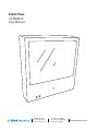
Public View CE-M8SD-B User Manual CLINTON Electronics 6701 Clinton Road Loves Park, IL 61111 1.800.447.3306 Sales 1.800.549.6393 Support 1.800.633.8712 Fax www.clintonelectronics.com Table of Contents Display DVR Camera Introduction………………………………………………………………………… 3 Contents, Installation and Set-up…………………………………………………… 4 Display Functions…………………………………………………………………… 5 LCD Remote Control………………………………………………………………… 6 Display System Settings……………………………………………………………7-8 SD-Card Files………………………………………………………………………… 9 DVR Remote Control……………………………………………………………… 10 DVR Settings…………………………………………………………………………11 Playback…………………………………………………………………………… 12 Main menu, Date & Time……………………………………………………………13 Motion Detection……………………………………………………………………14 Recording Mode…………………………………………………………………15-16 Continuous Recording, DVR SD-Card Options…………………………………… 17 System Status, Power-On Setup, Factory Default………………………………… 18 Camera OSD Menu………………………………………………………………… 19 OSD Menu Navigation, Lens……………………………………………………… 20 Exposure…………………………………………………………………………… 21 White Balance……………………………………………………………………… 22 SSDR…………………………………………………………………………………23 BLC, HLC…………………………………………………………………………… 24 HLC………………………………………………………………………………… 25 DNR3……………………………………………………………………………… 26 Day/Night.………………………………………………………………………… 27 Special Image Adjust……………………………………………………………… 28 Image Adj. (continued), Monitor……………………………………… 28-29 Camera Title…………………………………………………………………30 Sync, Motion Detection…………………………………………………… 31 Motion (continued), Privacy……………………………………………… 32 Comm Adj. (continued), Language, Return, Exit………………………… 33 Troubleshooting ……………………………………………………………… 34-35 2 Introduction Congratulations on the purchase of your new Public View Integrated Camera Security display. This display and camera combination is designed for simple and effective loss prevention by making the viewer aware of video surveillance measures. Features: • Rugged Steel Enclosure • SD-Card Player • Single Channel DVR with SD-Card Storage • Motion Detection • Low Voltage power • Integrated High-Resolution Digital Day & Night Camera (600 TVL) • VESA mounting pattern for ceiling or wall mount options • Remote control operation of all screen adjustment features • Wide viewing angles • Video Output Precautions • There are no user serviceable parts inside the unit. Authorized service personnel must perform all service. To avoid electrical shock, do not disassemble the unit. Any attempt to disassemble the unit will void the warranty. • Verify DC power supply before installation. This unit requires an external AC to DC power supply capable of supplying sufficient DC voltage to the display. • Install the monitor in a location that is suitable for the display. Make sure there is adequate ventilation around the unit, and that the display is mounted securely to its support structure. • Do not place the monitor in direct sunlight, or near sources of heat. • Do not place the monitor in a damp area. • Do not place the monitor in an area that is below 40˚F. • Clean the monitor with water or non-ammonia glass cleaners only. Do not use abrasive cleaners, abrasives, or highly concentrated ammonia to clean the front of the display. Clean with a damp cloth only, do not spray directly with water. 3 POWER PACKAGE CONTENTS UP AUTO MENU DOWN 2 GB SD Card 2 2 GB SD Card 2 16 GB SD Card GB SD Card 2 GB SD Card 16 GB SD Card 16 16 GB SD Card GB 2 16 16 GB SD Card GB SD Card GB SD Card SD Card GB SD Card 2 GB SD Card CE-M8SD-B with access door and security screw Security Allen Wrench Extra Security Screw 16 GB SD-Card (for DVR) 2 GB SD-Card (for media) Alarm SD-Audio Motion Chime 1 ON 2 3 4 Remote Control (batteries included) Power Pigtail (for Hardwiring) 16 GB SD Card User Manual Alarm Plug Installation and Set up Unpacking your display WHEN SD CARD IS INSERTED, YOU MUST POWER CYCLE. You can do this by pushing the POWER button on the long remote, or by unplugging the power cord from the wall. Your Public View display comes with all of the items shown above. Carefully remove the display from its packing and set the unit on a firm surface. Save the packing in case of future service requirements. WHEN SD CARD IS INSERTED, YOU MUST POWER CYCLE. WHEN SD CARD IS INSERTED,WHEN SD CARD IS INSERTED, WHEN SD CARD IS INSERTED, YOU MUST POWER CYCLE. You can do this by pushing the POWER YOU MUST POWER CYCLE. YOU MUST POWER CYCLE. You can do this by pushing the POWER can do this by pushing the POWER button on the long remote, You can do this by pushing the You POWER or by unplugging the power cord from the wall. button on the long remote, button on the long remote, button on the long remote, or by unplugging the power cord the wall.the power cord or by unplugging or byfrom unplugging from the wall. the power cord from the wall. WHEN SD CARD IS INSERTED, YOU MUST POWER CYCLE. You can do this by pushing the POWER button on the long remote, or by unplugging the power cord from the wall. Installation of the display The display should be located where it will have the most effect on deterring potential shoplifting. Keep in mind the lighting conditions, viewing area, ease of installation, and distance from the power supply when choosing a location. The display is compatible with many available wall and ceiling mounts, consult your dealer for suggestions. The rear of the display has a VESA 75mm & 100mm mounting patterns that accepts M4x8mm screws. Please refer to the installation instructions on the particular mounting bracket and details of how to install. Connecting the display This display requires a 24V DC power supply. Locate the applicable AC to DC power supply in a suitable location where there is a power source, and access to run the low voltage cable to the display. For single unit power supplies, you will need to keep the distance from the power supply to the display less than 75 ft. For multiple unit power supplies, the power supply can be located at further distances from the displays at a central location. Please refer to the specific power supply installation instructions for recommended wire size and distances. Caution: Do not connect the power connector to the display when energized, doing so may damage the electronics inside the display. Connect power supply to unit, then to 120v wall outlet. 4 Display Functions 2 GB SD Card 16 GB SD Card Features VESA 75 & VESA 100 mounting patterns Power Supply Input Video SD-card slot BNC Output Alarm Connection DVR SD-card slot Camera Camera OSD Joystick LED Flasher IR Sensor Control Access The access door for the OSD Joystick, SD-Cards, and Connections on the back of the unit WHEN is SDlocated CARD IS INSERTED, YOU MUST POWER CYCLE. and must be removed using the included security allen wrench. 2 16 You can do this by pushing the POWER GB button on the long remote, or by unplugging the power cord from the wall. SD Card 5 GB SD Card WHEN SD CARD IS INSERTED, YOU MUST POWER CYCLE. You can do this by pushing the POWER button on the long remote, Remote Control - LCD The parameters of the display can be adjusted by using the included remote control. LCD CONTROLS Power Mute Selection Arrows Menu DVR AV DVR CONTROLS REC (see page 10 for DVR controls) MENU OSD Exit SOURCE 912-F8125-0001 LCD CONTROLS Power – On/Off function. This will power off the display only. The internal camera can still supply video to an external display or DVR. Mute –Disables the audio on the unit. Menu – Adjustment of audio, video, signal, tools, & language. • Push MENU button once. • Use arrow buttons located around the MENU button to pick category. • When correct category is chosen, press VOL- and VOL+ buttons to adjust given parameter of display. • When adjustment of selected parameter is done, press MENU to go back to the previous screen, or simply wait for the menu screen to time out. Selection Arrows – Use in conjunction with the menu button to navigate and make adjustments. 6 Display Set-Up Video Menu: The display should be pre-set for most installations, however if some adjustment is necessary, we suggest you follow these recommendations by pressing the MENU button on the remote control: 1. First adjust the BRIGHTNESS control to set the black level so that the images are at their brightest while the black images are still black. Do not adjust too high where the black portions of the image become gray or the image will have a “washed out” appearance. 2. Set the CONTRAST control to set the white level so that the images are at their brightest without losing definition in the white portions of the image. 3. Adjust the COLOR control to achieve a realistic image of the items within the viewing area. 4. Adjust the TINT control if the image has bluish or reddish tint to the white portions of the image. 5. Decrease the SHARPNESS if the image appears too grainy or pixelated. Increase the SHARPNESS if the image appears too soft. 6. With VIDEO MODE, you can select from various preset configurations. These include Normal, Nature, Cinema, Sport, Vivid. 7. The RESET function will reset the levels in the video menu only. Audio Menu 1. The Audio Menu can be used to raise or lower the volume of the chime or SD-Card activated audio. *NOTE: The MUTE function on the remote control will disable the audio/chime sound. 2. Select the audio source by selecting CHIME to enable the built in chime sound, or SD-AUDIO for the audio on the SD-Card to play. 7 System Settings Menu 1. The ALARM CAMERA DWELL will allow you to change the duration that the camera image will remain on screen after an alarm event has occurred. If you wish to change this duration for motion events, you must do so in the DVR Settings menu. See pg. 16 for details. 2. The LANGUAGE can be changed to one of the following: English, French, German, Spanish, Italian, Dutch, Greek, Swedish. 3. In OSD CONTROL you can control the following: 3a. HORIZONTAL - Adjusts the horizontal position of the OSD. 3b. VERTICAL - Adjusts the vertical position of the OSD. 3c. ROTATION - Flips the OSD orientation to one of the following: Normal, Mirror, Left, Right, Down 3d. OSD TIMER - Set the duration the OSD menu will remain on screen after button is pressed. 4. With DETECT you can select for the camera image to show upon motion, or upon alarm event. 5. In the MESSAGE CONTROL section you can set the following: 5a. ON / OFF - Turns the message on the bottom of the screen on or off. 5b. MESSAGE - Select the message to read “WELCOME” or “RECORDING IN PROGRESS”. 5c. FLASH - Control the message to flash on and off, or be steady on. 5d. LED CONTROL - Disable or enable the flashing LED on the front of the device. 6. FACTORY RECALL will reset the device to the factory presets. 8 SD Card SD Card Change SD-Card Image/Video/Audio • Insert the SD-Card into your computer or SD-Card reader. • Move the desired JPEG image, or AVI video file into the SD-Card folder. (For the M8SD-B the desired full screen image size is 800x600) • Leaving multiple media files on the SD-Card will result in the device cycling through all loaded media. • Insert the SD-Card back into the PVM with the contacts facing out, as shown on the rightDO NOT FORCE IT IN. *NOTE: If you wish to not display SD-Card content, you must set “Alarm Camera Dwell” to “On”, and “Detect” to “Alarm” WHEN SD CARD IS INSERTED, YOU MUST POWER CYCLE. You can do this by pushing the POWER button on the long remote, or by unplugging the power cord from the wall. 9 Remote Control -DVR The parameters of the display can be adjusted by using the included remote control. LCD CONTROLS (see page 6 for LCD controls) DVR AV DVR CONTROLS REC Play / Pause OSD Exit Exit / Stop Down Record MENU Back / Rewind Up Forward / Fast Forward OSD Controls SOURCE 912-F8125-0001 Menu / OK Source DVR CONTROLS Play / Pause –Press once to play, press again to pause playback. Menu/OK – Use to open Menu and to select functions. Up, Down, Back, Forward Selection Arrows – Use in conjunction with the menu button to navigate and make adjustments. Also used to Fast Forward or Fast Reverse in playback mode. OSD Controls – Toggles the OSD functions on screen. Record – Not used (recording begins automatically when unit is on). To scheduling a recording see pg. 15. Source – Press to toggle from DVR screen to live view. Exit / Stop – Press to stop playback. Also used to exit the current selection to previous screen. 10 DVR Settings Recording View 2011 2 1 3 4 5 6 720 480 7 8 9 HQ Select from: Yr / Mo / Day or Mo / Day / Yr, 1 Current Date & Time 2 Record Status Device is Recording Data 3 Record Mode Manual Record 4 Video Size 360 Quarter VGA Quality 240 360 x 240 HOUR : MINUTE : SECOND Schedule Record 720 480 Motion Record VGA Quality 720 x 480 5 Recording Quality BQ Basic Quality NQ 6 Audio Status No Audio recording supported with this device (Disregard Audio Symbol) Normal Quality HQ High Quality 7 SD Card Status DVR SD Card Present DVR SD Card NOT Present 8 Record Storage Mode “Loop” Mode Overwrite is Active Mode 0% “Stop” Shows % of Storage Space Used 9 Battery Level Battery Level is not supported with this device (Disregard this symbol) 11 Playback view To start playback you can decide between three different modes. DVR Normal playback During live view press the playback/pause DVR AV REC button to start normal playback. DVR AV AV MENU Normal playback speed. During the normal playback press or button to rewind or fast forward. By pressing in the REC same direction again you raise the search speed (Speed: x2/ x4/ x8/ x16/ x32). Press button to DVR AV playback at normal speed. MENU Exit MENU Exit Exit REC REC OSD DVR OSD OSD DVR DVR DVR AV During playback, press MENU REC After pressing Pause button you can search frame by frame, using OSD Exit button to playback at normal speed. MENU AV AV REC pause playback and press again to return to playback OSD Exit button to status. REC Exit Exit AV DVR Press the exit AV MENU or MENU Exit MENU OSD REC button. Press OSD button OSD to stop playback and to return to live view. REC MENU Exit OSD Event list Playback In order to open the search menu open the main menu and select the menu item SEARCH & PLAY. DVR AV DVR AV REC 1 The file view shows the date of recording and the number of files belonging to the recording. To MENU navigate press the direction button up or down and press button to playback. To return to OSD Exit the selection mode press the exit button. REC MENU Exit OSD 2 Shows the number of pages. 3 Record Mode: Manual Record 4 Press the direction button right or left in order to show the first picture of the event. 5 Shows the time of the recording. Schedule Record Motion Detection Record Playback using a Computer: • Push down on the DVR’s SD Card to eject the card. • Pull the card out and insert into your computer or SD Card reader. • On your computer, select the SD Card folder. Search through the segmented files to find your desired clip. • Open the clip in Windows Media Player to view. Clips are in MPEG4 format. If you can not playback the clip, you may need to download an update for your Windows Media Player. *NOTE: The last file on the SD Card may be corrupted due to pulling it from the unit. This 3MB file will not affect the desired recording as it is only the last few seconds before the SD Card was pulled. *NOTE: The DVR uses an SDHC Card. You must have a computer or card reader capable of reading an SDHC Card to view files on your computer. 12 Main Menu 1 The menu level is shown in the top right corner of the menu screen. First level (main menu) Second level DVR AV Third level DVR DVR MENU AV DVR REC AV DVR AV AV - Press or buttons to navigate. REC - To confirm or select, press button. MENU - Press or buttons to change the value. - Press Exit buttonOSD to exit the menu. REC Exit Exit REC MENU OSD REC OSD REC MENU Exit OSD OSD DVR OSD MENU MENU Exit Exit AV Date / time setup DST : OFF Date Format Here you can change the way the date is displayed. Date/ Time Adjustment Here you can change the date and time. DST Here you can enable or disable daylight savings time. 13 Motion setup SET MD AREA DVR AV The motion detection area is split up into 16 x 12 cells. Cells which are marked to detect motion are displayed red. DVR DVR DVR AV AV DVR REC REC MENU REC MENU OSD Exit OSD MENU Exit Exit MENU OSD OSD Exit REC MENU button. Press play- OSD Exit AV CELL EDIT Here you can (de-) activate every single cell. DEL BLOCK Here you can deactivate a complete block of cells. DEL ALL Here you can deactivate all cells at once. ADD BLOCK Here you can activate a complete block of cells. ADD ALL Here you can activate all cells at once. SET MD SENSITIVITY Here you can set the sensitivity of motion detection. DVR DVR AV AV MD ENERGY Shows the current recognized motion. MD THRESHOLD By pressing the buttons or you can set the value when motion detection is triggered. The lower the value is set the more sensitive motion detection reacts. More bars = More sensitive REC MENU Exit Exit 14 REC MENU OSD OSD REC MENU DVR Editing modes: AV REC In order to navigate use buttons and confirm by pressing back button in order to change the editing mode. Exit AV OSD Manual record AUDIO : OFF - VIDEO SIZE / FRAME RATE: Here you can change the video size and frame rate for the manual recording. Video size 360 x 240 720 x 480 Max. frame rate 30 fps 30 fps - QUALITY: Here you can choose between three recording qualities: Basic, Normal, High - AUDIO: This feature is non functioning on this device. Schedule record Here you can see a short a summary of the settings for motion and continuous recording. EVENT SCHEDULE SETUP Activate / Deactivate the schedule and the recording settings. EVENT RECORD Settings for the event-activated recording. CONTINUE RECORD Settings for continuous recording. 15 DVR AV Schedule setup REC SCHEDULE Recording ON / OFF (default value is OFF) DVR DVR AV AV MENU Use to navigate between the hours. Press or to change the recording types. ( : Motion; : Continuous; Alarm; _: All modes active; : No mode active) Exit OSD 00 - 23 Exit MENU Exit MENU REC OSD REC MENU OSD Exit OSD DVR REC AV Event record Here you can change the settings for the motion detection. EVENT VIDEO SIZE AUDIO : OFF PRE-RECORD : 5 Here you can set the recording resolution FRAME RATE Here you can set up how many fps will be recorded. QUALITY Here you can set the recording quality. AUDIO Audio recording is not available on this device. Disregard this menu item. DURATION Here you can set how long the device will record after motion has been detected. PRE-RECORD Here you can set the duration of time that video will be stored prior to motion detection being activated. (from 0-10 seconds). 16 Continue record Here you can change the settings for the continuous recording. AUDIO VIDEO SIZE : OFF Here you can set the recording resolution FRAME RATE Here you can set up how many fps will be recorded. QUALITY Here you can set the recording quality. AUDIO Audio recording is not available on this device. Disregard this menu item. SD-Card Options DISK TOTAL Shows the total capacity of the inserted SD-Card. DISK REMAIN Shows the remaining capacity of the inserted SD-Card. MAX FILE SIZE Here you can set the max. file size (3 – 100 MB) of a recording. If the size is reached a new file is created. CARD FULL Here you can choose what happens when the total capacity of the SD-Card is reached: STOP The recording is stopped. LOOP The recording continues. The oldest files are replaced by the new recordings. FORMAT Here you can format the SD-Card. All recordings will be deleted. 17 System Status Here you can find a quick summary of the firmware version and the recording settings. Press any key to return to the main menu. Power on Setup ALARM INPUT : N.C. LANGUAGE Here you can set the OSD menu language. COMPOSITE Here the video standard for the video output is shown. ALARM INPUT Here the alarm input can be set. (normally closed; normally open) Factory Default DVR AV Here you can reset all settings, except Date and Time, to factory default. DVR Press Press MENU REC AV button to reset to factory default. buttonRECto cancel factory default and return to the main menu. OSD Exit MENU Exit OSD 18 Camera OSD Menu Camera functions and settings can be adjusted or changed by activating the OSD menu. When the OSD menu is activated text will display on the monitor. The user can then move the cursor to the desired function to change the setting. SETUP Menu LENS • DC MANUAL EXPOSURE • BRIGHTNESS • SENS-UP • SHUTTER • RETURN • AGC WHITE BALANCE • ATW • MANUAL • OUTDOOR • AWC SET • INDOOR SSDR • OFF • ON BACKLIGHT • OFF • BLC DNR3 • OFF • ON DAY / NIGHT • AUTO • EXTERN • COLOR • B/W SPECIAL • IMAGE ADJ. • SYNC • COMM ADJ • MONITOR • MOTION DET • LANGUAGE • CAM TITLE • PRIVACY • RETURN EXIT • SAVE • NOT SAVE • RESET Accessing the OSD Menu 2 GB SD Card 16 • HLC GB SD Card Settings can be adjusted using the joystick located on the back of the device. Camera OSD Joystick WHEN SD CARD IS INSERTED, YOU MUST POWER CYCLE. You can do this by pushing the POWER button on the long remote, or by unplugging the power cord from the wall. 19 Navigating the OSD Menu 1.Press the SETUP button, then select a menu item from the list available by using the UP and DOWN buttons. •Functions are selected using up and down buttons. •Place the cursor over a desired item, the selected position is displayed. Select the function using the UP or DOWN button. When an arrow is present, press SETUP button to enter sub-menu Change the status using the LEFT or RIGHT button. 2. Set up a selected item by using the Left and Right buttons. 3. To finish the settings, select ‘EXIT’ and press the SET button. Notes •An item with the icon also has sub menus. To select a sub menu, select an item with the icon and press the SET button. •An item with the - - - icon has no sub-menus available for selection. LENS (Adjusting the brightness level) Using this function, you can control the screen brightness. 1. When the SETUP menu screen is displayed, select ‘LENS’ by using the Up and Down buttons so that the arrow indicates ‘LENS’. 2. Press SETUP to enter the sub menu and adjust the following. – BRIGHTNESS : Adjusts the video brightness (selectable from 1 - 70). Notes •If color rolling occurs when using a DC lens, set Shutter to FLK. •Some lenses may not work properly, depending on the setting of the BRIGHTNESS LEVEL. 20 Exposure 1. When the SETUP menu is displayed, select ‘EXPOSURE’ by using the Up and Down buttons so that the arrow indicates ‘EXPOSURE’. Press SETUP to enter. 2. Select the desired mode using Up and Down buttons. BRIGHTNESS: Adjusts the exposure brightness. SHUTTER: You can select either auto or manual shutter. – A.FLK: Select this when you experience picture flicker, which can happen when there is a clash with the frequency of the installed lighting. – ESC : Select this to control the shutter speed automatically. If ESC is selected, the shutter speed is automatically controlled depending on the ambient illumination of the subject. – MANUAL: You can control shutter speed manually. (1/60 ~ 1/120,000) Notes •When using a DC lens, set the shutter mode to A.FLK if color rolling occurs. •When the SHUTTER is set to ESC after selecting Internal Synchronization Type, the picture may become unstable if the camera faces a bright fluorescent light. Therefore, take care when choosing the installation position. •When the SHUTTER is set to MANUAL or A.FLK mode, SENS-UP will be disabled. AGC (AUTO GAIN CONTROL) :The higher the gain level, the brighter the screen, but the higher the noise. – OFF : Deactivates the AGC function. – LOW : Allows automatic gain control from 5.3dB to 32dB. – HIGH: Allows automatic gain control from 5.3dB to 37dB. SENS-UP: When it is night or dark, the camera automatically detects the light level and maintains a clear picture if this mode is activated. – OFF : Deactivates the SENS-UP function. – AUTO : Activates the SENS-UP function. RETURN:Select this to save the changes in the EXPOSURE menu and return to the SETUP menu. 21 Exposure- continued Notes •If you press the SET button in ‘AUTO’ mode, you can adjust brightness by increasing or decreasing the shutter speed. (x2 ~ x512) •Note that the higher the zoom level, the brighter the screen, but the more likely it is that an afterimage will appear. •Although noise, spots, and whitish symptoms may occur in SENS-UP operation when the zoom level is increased, this is normal. White Balance Control Use the White Balance function to adjust the screen color. 1. When the SETUP menu screen is displayed, select ‘WHITE BAL’ by using the Up and Down buttons so that the arrow indicates ‘WHITE BAL’. 2.Select a desired mode using the Left and Right buttons. t Select one of the following 5 modes, as appropriate for your purpose. ATW : Select this when the color temperature is between1,700°K and 11,000°K. OUTDOOR : Select this when the color temperature is between1,700°K and 11,000°K (sodium light inclusion) INDOOR : Select this when the color temperature is between 4,500°K and 8,500°K. MANUAL : Select this to fine-tune White Balance manually. Set White Balance first by using the ATW or AWC mode. After that switch to MANUAL mode, fine-tune the White Balance and then press the SET button. AWC SET : To find the optimal luminance level for the current environment, point the camera towards a sheet of white paper and press the Function Setup switch. If the environment changes, readjust it. Notes •White Balance may not work properly under the following conditions. In this case select the AWC mode. j When the color temperature of the environment surrounding the subject is out of the control range (ie. clear sky or sunset). k When the ambient illumination of the subject is dim. l If the camera is directed towards a fluorescent light or is installed in a place where illumination changes dramatically, the White Balance operation may become unstable. 22 SSDR (Super Dynamic Range) SSDR illuminates darker areas of an image while retaining the same light level for brighter areas to even out the overall brightness of images with high contrast between bright and dark areas. 1. When the SETUP menu screen is displayed, select ‘SSDR’ by using the Up and Down buttons so that the arrow indicates ‘SSDR’. 2. Turn on by using the Left/Right buttons and press SETUP to change the SSDR level in the sub- menu according to the contrast between bright and dark areas. SSDR OFF SSDR ON 23 BLC (Back Light Compensation) 1. When the SETUP menu screen is displayed, select ‘BACKLIGHT’ by using the Up and Down buttons so that the arrow indicates ‘BACKLIGHT’. 2.Select a desired mode using the Left and Right buttons depending on the camera purpose. BLC: Enables a user to select a desired area on a picture and view that area more clearly. BLC ON BLC OFF HLC (High Light Compensation) : If the scene contains extremely bright light areas such as from car headlight, the light can mask out much of the on-screen detail. Use HLC feature to remove these exceptionally bright lit areas to allow detail such as car license plate number to become visible. – LEVEL: Adjust level of the HLC function. – LIMIT: Enable to change the operating condition. – MASK COLOR/TONE : Change the color / brightness of the masking area. (Black, Red, Blue, Cyan, Magenta) – TOP/BOTTOM/LEFT/RIGHT : Adjust the area to be enhanced. HLC MASKING AREA HLC ON HLC OFF OFF : Not being used. 24 HLC continued 3. Select a desired mode using the Left and Right buttons and press the SET button. BLC : Select ‘BLC’ to adjust the area to be enhanced then adjust the level. HLC :Enable the user to change the level limit, mask color/tone and area. Notes •For effective license plate observation, it needs minimum illumination and fast shutter speed more than 1/200sec. •Because there can be a difference in the effectiveness of HLC according to the amount of light area in the screen, optimize the installation angle for the best HLC performance. •When dark, the HLC is only activated when a bright light exceeding a specific size in NIGHT ONLY mode. •The HLC is not activated in day light or when bright light is not present at night in NIGHT ONLY mode. 25 DNR3 This function reduces the background noise in a low luminance environment. 1. When the SETUP menu screen is displayed, select ‘DNR’ by using the Up and Down buttons so that the arrow indicates ‘DNR’. 2.Select a desired mode using the Left and Right buttons. OFF: Deactivates DNR. Noise is not reduced. ON : Activates DNR so that noise is reduced. 3. Set the DNR mode to ‘ON’ and press the SET button. Then you can adjust the noise reduction level. Notes •You cannot set the DNR to ‘ON’ or ‘OFF’ when the AGC mode of the EXPOSURE menu is ‘OFF’. •When adjusting the noise reduction level in DNR mode, remember that the higher the level is set, the greater the reduction in noise level, as will the brightness of the image. 26 Day / Night You can display pictures in color or black and white. 1. When the SETUP menu screen is displayed, select ‘DAY/NIGHT’ by using the Up and Down buttons so that the arrow indicates ‘DAY/NIGHT’. 2.Select a desired mode using the Left and Right buttons according to the picture display you want. EXTERN : This mode allows you to apply a desired filter to external signals. COLOR : The picture is always displayed in color. B/W: The picture is always displayed in black and white. You can turn on or off the burst signal on B/W mode. AUTO : The mode is switched to ‘Color’ in a normal environment, but switches to ‘B/W’ mode when ambient illumination is low. To set up the switching time for AUTO mode, press the SET button. You can turn on or off the burst signal on B/W mode. – DWELL TIME : You can select the duration time about changing the day/night mode. (3s, 5s, 7s, 10s, 15s, 20s, 30s, 40s, 60s) Notes •When using a Video Auto Iris Lens, if you set the lens level to low, automatic switching between Color and Black & White may not occur. •When AGC in the EXPOSURE menu is ‘OFF’, ‘ --- “ mode operates as like selecting ‘COLOR’ mode, and ‘AUTO’ mode can not be selected. 27 SPECIAL 1. When the SETUP menu screen is displayed, select ‘SPECIAL’ by using the Up and Down buttons so that the arrow indicates ‘SPECIAL’. Press SETUP to enter the ‘SPECIAL’ menu. 2. Select a desired mode using the Up and Down buttons. IMAGE ADJ: 1) When the SETUP menu screen is displayed, select ‘IMAGE ADJ.’ by using the Up and Down buttons so that the arrow indicates ‘IMAGE ADJ.’ Press SETUP to enter ‘IMAGE ADJ’. 2) Select a desired mode using the Up and Down buttons. l V-REV : You can flip the picture vertically on the screen. l H-REV : You can flip the picture horizontally on the screen. l D-ZOOM : You can use a digital zoom of x1 ~ x16. l DIS (Digital Image Stabilizer : This function mitigates any picture movement due to external factors such as wind. Notes •As the DIS function uses the digital zoom the camera’s resolution will decrease. •DIS doesn’t operate when background illumination is too low. •DIS doesn’t operate when object pattern is monotonic (ie. sky or white wall). 28 Image Adj. Continued l FONT COLOR : You can change the OSD font color. (White, Yellow, Green, Red, Blue) l SHARPNESS: As you increase this value, the picture outline becomes stronger and clearer. Adjust this value appropriately depending on the sharpness of the picture. l RETURN : Select this to save the settings for the IMAGE ADJ. menu and to return to the SETUP menu. Notes •When the V-REV or H-REV mode is enabled, the text on the screen does not flip. •If you increase the SHARPNESS level too high, the picture may become distorted or noise may appear. MONITOR : Change the settings value of video that is appropriate to your monitor. – LCD : Select this menu item when using a LCD monitor. – CRT : Select this menu item when using a CRT monitor. – USER : Use this menu item when using a monitor other than standard ones. You can change the gamma, PED level, and color gain in the sub menus. 29 CAM TITLE : If you enter a title, the title will appear on the monitor. 1) If the SPECIAL menu screen is displayed, use the Up and Down buttons so that the arrow indicates ‘CAM TITLE’. 2) Set it to ‘ON’ by using the Left and Right buttons. 3) Press the SET button. 4) Use the 4 direction buttons to move to a desired letter and select the letter by pressing the SET button. Repeat this to enter multiple letters. You can enter up to 15 letters. 5) Enter a title, move the cursor to ‘POS’ and press the SET button. The entered title appears on the screen. Select the position to display the title on the screen by using the 4 direction buttons and press the SET button. When the position is determined, select ‘END’ and press the SET button to return to the SPECIAL menu. Notes •When the CAM TITLE menu is ‘OFF’, no title will be displayed on the monitor screen even if you enter one. •Only English is available is this mode. •If you move the cursor to CLR and press the SET button, all the letters are deleted. To edit a letter, change the cursor to the bottom left arrow and press the SET button. Move the cursor over the letter to be edited, move the cursor to the letter to be inserted and then press the SET button. 30 SYNC : In areas where the supply is at 60Hz, you can synchronize the output phase of multiple cameras using the power synchronization function (Line-Lock) without using a synchronization signal generator. – INT: Internal Synchronization Type – L/L: Power Synchronization Type, Line-lock lPress the Function Setup switch. lYou can select a desired phase from 0 to 359 when select ‘phase’. Notes •When using AC power at 60Hz frequency, you can use the L/L type synchronization. •When the power is DC 12V, the SYNC menu is fixed to the ‘INT’ mode. MOTION DET : You can monitor activity more efficient with this feature allowing you to observe movement of objects in 8 different areas on the screen, and the words ‘MOTION DETECTED’ appear on the screen when movement is detected.. 1) When the SPECIAL menu screen is displayed, press the Up and Down buttons so that the arrow indicates ‘MOTION DET’. 31 Motion Detection- Continued 2) Set up the mode using the 4 direction buttons. – SENSITIVITY : You can select up to 8 MD areas. When SENSITIVITY number is high, motion detection sensitivity is increased to recognize even small movement. – AREA MODE : Determines whether to use the MD area selected in SENSITIVITY. – SEL POS: Determines which of the 4 vertices of each MD area is to be used. – XPOS : Determines the coordinate of the horizontal axis for SEL POS. – YPOS : Determines the coordinate of the vertical axis for SEL POS. – FILL SET : Fills in a selected MD area. The color of filling is sequentially selected as brown, orange, blue, cyan, green, yellow, magenta and red. – RETURN: Select this to save the MOTION DET menu settings and return to the SPECIAL menu. PRIVACY : Mask an area you want to hide on the screen. 1) When the SPECIAL menu screen is displayed, press the Up and Down buttons so that the arrow indicates ‘PRIVACY’. 2) Set up the mode using the 4 direction buttons. – AREA SEL : Select up to 12 PRIVACY areas. – MODE : Determines whether to use the area selected in the AREA SEL. – MASK COLOR : Determines area color. Select Green, Red, Blue, Black, White, Gray. – MASK TONE : Adjust the brightness of MASK COLOR. – TOP/BOTTOM/LEFT/RIGHT : Adjust the size and position of the selected area. – RETURN: Select this to save the PRIVACY menu settings and return to the SPECIAL menu. 32 COMM ADJ (Communication Adjustment) : This function sets up the camera communication status when controlling the camera through an external control device. 1) When the SPECIAL menu screen is displayed, press the Up and Down buttons so that the arrow indicates ‘COMM ADJ’. 2) Set up the mode using the 4 direction buttons. – CAM ID: Determines the camera’s identification number (between 0 and 255). – BAUD RATE : Select 2400/4800/9600/19200/38400/57600 bps. – UART MODE : Select NONE, EVEN or ODD for the parity bits. – RET PKT : Determines whether to send a command back to the controller device when a communication control command is sent to the camera. – DISP ID : Display the camera title on the top left corner of the screen. – PROTOCOL : STW(SPD), PELCO-D, PELCO-P, SEC, BOSCH, HONEY WELL, VICON, PANA. LANGUAGE : You can select the menu language according to your requirements. RETURN : Select this to save the SPECIAL menu settings and return to the MAIN SETUP menu. Exit Select a desired EXIT mode using the Left and Right buttons depending on the camera purpose. – SAVE: Save the current settings and exit the MAIN SETUP menu. – NOT SAVE : Do not save the current settings and exit the MAIN SETUP menu. – RESET: Resets the camera settings to the factory defaults. Language and Monitor settings are not initialized. 33 Troubleshooting If you have trouble operating your device, refer to the following table. If the guidelines do not enable you to solve the problem, contact Clinton Electronics Technical Support at 1-800-549-6393 or 815-633-1444. Problem Nothing appears on the screen. Solution •Check the power connection. •Check the Brightness of Auto Iris lens. •Press the POWER button on your remote control. •Check to ensure the proper voltage is applied to the display. In the case of long runs or small wire size, there may be a significant voltage drop to the display resulting in insufficient voltage to properly power the display. Consult your power supply manual to determine if the voltage can be increased to compensate. The video image is not clear. •Check if the screen and lens are clean. Clean with a clean cloth. •Adjust the contrast feature of the monitor. •Make sure that the screen is not exposed directly to a bright light •Enter the OSD settings of the display with the remote control. Go to the SHARPNESS setting and increase the value. NOTE: Pixelization in low light conditions is considered normal. The screen is dark. No Audio •Adjust the contrast feature of the monitor. •If you have an intermediate device, set the 75Ω/Hi-z properly, and check the terminals. •Adjust the brightness level of the lens in the camera OSD menu. • Make sure the mute function is not activated. • Turn up the volume. • If using chime sound, make sure audio output is set to “Chime”. • If using SD-Card audio, make sure it is a supported audio format. 34 Troubleshooting Problem The MOTION DETECTION function is not working. Solution •Check if ‘MOTION DETECTION’ mode is turned on. •Check if the MD LEVEL is too low. •Check the setting of the MD AREA. Colors are not quite right. •Check the ‘WHITE BAL’ setting. The screen is flickering. •Check if the camera is facing directly into sunlight or fluorescent light. COLOR (DAY & NIGHT) mode is not working. •Check if the AGC menu is set to the OFF position. SENS-UP function is not working. •Check if the AGC menu is set to the OFF position. •Check the limit of SENS-UP AUTO mode. When no motion is present, the screen turns to a blue “Settings” image. •Check that the SD-Card player has an SD-Card properly inserted and has an AVI or JPEG file loaded on it. 35 v.11.01.11