1
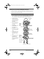
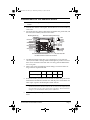
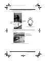
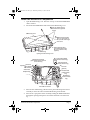
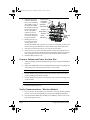
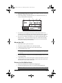
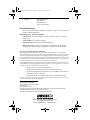
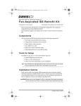
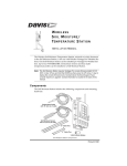
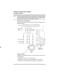
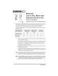
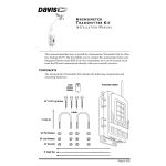
ISS2 RetroKit D011.fm Page 1 Wednesday, February 19, 2003 6:02 PM
Va n ta g e P r o ® I S S R e t r o f i t K i t
I NS TR UC TION S
E stimate d Time R equir ed: 30 Minutes
This Instruction Sheet describes how to install the ISS Retrofit Kit for a Vantage
Pro® or Vantatge Pro Plus Integrated Sensor Suite (ISS).
Components
The ISS Retrofit Kit includes the following components and hardware:
• New Sensor Interface Module (SIM) preinstalled in a SIM housing,
attached to a new bottom radiation shield plate along with a new separate Temp/Hum sensor module
• Three long screws with nuts, flat washers, and lock washers
• One 3-volt CR-123A lithium battery
Tools for Setup
In addition to the kit, you will need the following tools:
• 7/16” (12mm) wrench or adjustable wrench
• Phillips screw driver
• Hammer
• Pliers
Overview of Kit Installation
1.
Remove the ISS from its Mounted Position
2.
Dissassemble the ISS Radiation Shield
3.
Install the Retrofit Kit components
4.
Connect Cables and Power the New SIM
5.
Verify Communications - Wireless Models
6.
Mount the ISS
7.
Return the Old SIM to Davis
Product # 6920, 6920C
ISS2 RetroKit D011.fm Page 2 Wednesday, February 19, 2003 6:02 PM
Remove the ISS from its Mounted Position
In order to take down your ISS you will first need to disconnect the anemometer cable. If you have a Cabled Vantage Pro station, you will also need to disconnect the console cable from the ISS.
CAUTION:Please work on your Vantage Pro ISS in a safe place.
1.
At your Vantage Pro console, press and hold the DONE key and then press
the “-” (down arrow) key to put the console in Setup Mode. This will prevent the reception of erroneous rain counts from the rain collector.
2.
At the ISS, remove
and discard the three
(3) wing nuts from the
bottom of the radiation shield.
3.
Remove the three (3)
bottom plates from
the shield.
4.
Set aside the two open
(middle) plates.
5.
Discard the bottom
closed plate.
6.
Disconnect the WIND
sensor (anemometer)
cable.
7.
Cabled Stations Only:
Disconnect the Console cable from the
SIM.
8.
You can now remove
the ISS from it’s
mounted position.
Move it to a safe place
to install the kit components.
Rain Collector
Base
Sensor
Interface
Module
(SIM)
Top Closed Plate
(Save this plate)
Antenna
Open Plate
(Save this plate)
Open Plate
(Save this plate)
Antenna
Deployment
Hole
(Wireless only)
Bottom Closed Plate
(Discard this plate)
#8 Flat Washer
#8 Lock Washer
#8 Wing Nut
Opening the Radiation Shield
Page 2
Vantage Pro® ISS Retrofit Kit
ISS2 RetroKit D011.fm Page 3 Wednesday, February 19, 2003 6:02 PM
Dissassemble the ISS Radiation Shield
Note:We recommend using a workbench or equivalent flat surface for the following procedures.
1.
With the rain collector cone in place, turn the ISS over so it rests on the top
of the cone.
2.
Disconnect the rain collector cable and (if present) the solar panel cable, and
the SUN (solar radiation) and UV sensor cables.
Mounting Screws (4)
Solar Panel Cable (wireless only)
3-Volt
Lithium
Battery
(wireless
only)
AC Power
(optional)
UV Sensor
UV
SUN
Solar Sensor
WIND
Anemometer
CONSOLE
RAIN
Rain Collector
Console Cable
(cabled only)
Green Test LED
DavisTalk Transmitter ID Switches
Old SIM Connections and Screw Locations
3.
The SIM transmitter board, dust cover, and small rear cover plate (not
shown) are attached to the top radiation shield plate by 4 screws. Unscrew
these screws and remove the front dust cover along with the SIM and the
rear cover plate.
4.
Make a note of the transmitter ID switch settings. You will use these settings in the new replacement SIM.
Switch Position
Switch Setting
5.
1
2
3
4
OFF
Remove the battery from the circuit board and set all ID code positions ON.
With all the transmitter ID switches set to ON, the power stored in the old
SIM’s super capacitor should dissipate within one hour.
Note:Setting the #1, 2 and 3 ID switches to ON will set your transmitter ID to “8”. Setting the
#4 ID switch will turn on the ISS test mode. Set the #1, 2 and 3 switches differently if you
are using Station 8 in your weather station. Refer to Appendix A.”Wireless Transmitter
Settings” in your ISS Installation Manual for more information.
6.
Save the battery as a back-up and set aside the SIM board for return to
Davis.
Dissassemble the ISS Radiation Shield
Page 3
ISS2 RetroKit D011.fm Page 4 Wednesday, February 19, 2003 6:02 PM
7.
Hammer the three (3) long radiation shield screws down into the base. The
screws should move fairly easily with light taps from a hammer.
8.
Remove the rain collector cone.
Top closed
radiation
shield
plate
Pound the 3
long screws
down into the
base.
Twist off the rain collector cone.
9.
Pull the top closed radiation shield plate off or use pliers to hold the pushnuts while you unscrew the screws, then discard the old screws, push-nuts
and washers.
Remove push nuts
from the 3 long screws,
then remove the screws.
10. Save the top closed radiation shield plate for later use.
Page 4
Vantage Pro® ISS Retrofit Kit
ISS2 RetroKit D011.fm Page 5 Wednesday, February 19, 2003 6:02 PM
Install the Retrofit Kit Components
1.
Open the SIM housing cover. Note the “S-loop” in which the TEMP-HUM
cable is formed.
2.
Disconnect the TEMP-HUM cable and close the SIM housing cover.
1
Use your thumbs to push
back on the two (2) plastic
latches.
SIM Housing Cover
2
SIM Housing
With the latches pushed
back, use your fingers to
lift up on the corner edges
of the cover.
Screw Fastening Holes.
Use self-threading screws:
#6 x 0.5" (3.5mm x 12 mm)
(optional)
Opening the SIM Housing Cover
Cable Routing Channels
(press cables fully into channel
to form "S-loop")
Optional
UV Sensor
Solar Radiation
Rain Collector
3-Volt Lithium Battery
(wireless models only)
Solar Panel Power
(wireless models only)
AC Power
(optional)
Anemometer
Console Cable
(cabled models
only)
Temp/Humidity
DIP Switches
(wireless models
only)
New SIM Connections
3.
Place the new SIM housing, radiation sensor plate and Temp/Hum sensor
assembly on the work surface with the SIM housing on the bottom.
4.
Place the two open plates on the Assembly, feeding the TEMP-HUM cable
through the opening in the plates. Be sure that the three screw holes line
up.
Install the Retrofit Kit Components
Page 5
ISS2 RetroKit D011.fm Page 6 Wednesday, February 19, 2003 6:02 PM
5.
6.
Place the top closed
radiation shield plate
that you saved during
disassembly on top of
the stack. The TEMPHUM cable should exit
between the upper of
the two open plates
and the top closed
plate, in the direction
towards the SIM housing cable channels.
3 3/4 Inch Screw
Lock Washer
Flat Washer
Solar Power
Cable Routing
Top Plate
Middle Plates
Temp/Hum
Sensor
TEMP-HUM
Cable
Routing
SIM Housing
Holding the rain collector base above the
stack of plates, place
the SOLAR PANEL cable, if present, across the top of the plates so that it runs
between the top plate and the base, and from the front to back of the base).
7.
Place the rain collector base down on top of the stack of plates.
8.
Insert the 3 screws, with lock washers and flat washers, through the rain collector base and radiation shield plates into the threaded inserts in the bottom
plate (see figure). Use the screws to fasten the radiation shield to the base.
9.
Install the Rain Collector cone.
Connect Cables and Power the New Sim
1.
Turn the assembly upside-down(SIM housing on top) and open the SIM housing cover.
2.
Plug in the TEMP-HUM sensor and the RAIN cable, and if present, plug in the
solar panel power cable and the SUN and UV sensor cables.
Note:Be sure to push the cables deep into the cable channels to form S-loops (see figure).
3.
Wireless Models Only: Install the battery. Be careful to observe the battery
polarity markings on the battery holder.
4.
Wireless Models Only: Set the transmitter ID code to match the settings used
on the old SIM.
Note:Make sure the transmitter DIP switch #4 on the new SIM is in the OFF position.
5.
Close the SIM housing cover.
Verify Communications - Wireless Models
1.
If your console is in Setup Mode, you will need to exit Setup Mode to perform
this test. You can exit Setup Mode by pressing and holding the DONE key.
2.
Press and hold the TEMP key and then press TIME key on the console to display the Diagnostic Screen.
Page 6
Vantage Pro® ISS Retrofit Kit
ISS2 RetroKit D011.fm Page 7 Wednesday, February 19, 2003 6:02 PM
3.
Press the 2nd key then press and hold the CLEAR key until all transmission
diagnostic counters are reset to zero.
4.
View the Percentage of Packets Received, #5 in the illustration below, to
verify communication with the ISS.
4
3
5
1
2
am
6
Last 24
days
Every 1
7
9
8
day
14
10
11
Vertical Scale:
STATION NO.
10
13
5
12
5.
If you are not receiving data from the ISS, check that the battery was
installed correctly and that the transmitter ID switches are set correctly. If
you are still not receiving data please contact Davis Technical Support.
6.
If you are successfully receiving data, press and hold the DONE key and
then press the “-” (down arrow) key to put the console back into Setup
Mode. This will prevent the reception of erroneous rain counts from the
rain collector while you mount the ISS.
Mount the ISS
1.
Mount the ISS in its previous location.
2.
All Stations: Plug the WIND sensor cable into the SIM.
3.
Cabled Stations Only: Plug the Console cable into the SIM.
4.
Close the SIM housing cover.
Note:If desired, you can more securely fasten the SIM housing cover by using self-threading
screws in the holes provided for that purpose. See the SIM Housing Cover illustration
for details.
5.
At your Vantage Pro console: Press and hold the DONE key on the console
to exit Setup Mode.
6.
Cabled Models Only: Verify the reception of data from the ISS at your Vantage Pro console. If you are not receiving weather data at the console double-check the console cable connections.
Return the Old SIM to Davis
1.
Return the old SIM in the ISS Retrofit Kit shipping box.
2.
Include the shipping paperwork you received with the Retrofit Kit.
Note:Wireless Models Only: Please be sure to remove the battery before shipping the old SIM.
Mount the ISS
Page 7
ISS2 RetroKit D011.fm Page 8 Wednesday, February 19, 2003 6:02 PM
3.
Ship to:
Davis Instruments
Attn: Returns
3465 Diablo Ave.
Hayward, CA 94545
Troubleshooting
Please contact Davis Technical Support if you have any questions or problems
installing the ISS Retrofit Kit.
Contacting Davis Technical Support
(510) 732-7814 for Technical Support, Monday – Friday, 7:00 a.m. – 5:30 p.m.
Pacific Time.
(510) 670-0589 Fax to Technical Support.
[email protected] E-mail to Technical Support.
www.davisnet.com Copies of User Manuals are available from the Weather
Support page. Watch for FAQs and updates. Subscribe to the e-newsletter.
FCC Part 15 Class B Registration Warning
This equipment has been tested and found to comply with the limits for a class B digital
device, pursuant to Part 15 of the FCC Rules. These limits are designed to provide reasonable
protection against harmful interference in a residential installation. This equipment generates,
uses and can radiate radio frequency energy and, if not installed and used in accordance with
the instructions, may cause harmful interference to radio communications. However, there is
no guarantee that interference will not occur in a particular installation.
If this equipment does cause harmful interference to radio or television reception, which can
be determined by turning the equipment off and on, the user is encouraged to try to correct the
interference by one or more of the following measures:
• Reorient or relocate the receiving antenna.
• Increase the separation between the equipment and receiver.
• Connect the equipment into an outlet on a circuit different from that to
which the receiver is connected.
• Consult the dealer or an experienced radio/TV technician for help.
Changes or modifications not expressly approved in writing by Davis Instruments may void
the user’s authority to operate this equipment.
Product Numbers: 6920, 6920C
Davis Instruments Part Number: 7395.307
ISS Retrofit Kit
Rev. B Manual (02/19/03)
This product complies with the essential protection requirements of the EC EMC Directve 89/336/EC.
Copyright ©2003 Davis Instruments Corp. All rights reserved.
Vantage Pro is a registered trademark of Davis Instruments Corporation.
3465 Diablo Avenue, Hayward, CA 94545-2778 U.S.A.
510-732-9229 • Fax: 510-732-9188
E-mail: [email protected] • www.davisnet.com