1
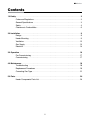
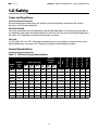
Detroit Radiant Products Co.
DR Series Manual
0086
!
Gas Fired Radiant
Plaque Heater
Installation, Operation,
Maintenance and Parts
!
WARNING
Read these instructions carefully before attempting to install, operate or service the heater.
This heater must be installed and serviced by a Gas Safe Gas Engineer only!
Conversion of the heater for use with other gases must be carried out by a Gas Safe
Gas Engineer.
All persons involved with the installation, operation and maintenance of the heater
system must read and understand the information in this manual. Failure to comply
with these warnings and instructions, or those on the heater, could result in personal
injury, death, fire, asphyxiation and/or property damage.
Not for domestic use!
This unflued, gas fired, overhead radiant heater is designed for use in industrial and commercial
building such as warehouses, manufacturing plants, aircraft hangars, service garages, etc.
This heater is not approved in any domestic application. This includes (but is not limited to) the home,
living quarters, attached garages, etc. Installation in domestic indoor spaces may result in property
damage, asphyxiation, serious injury or death.
The manufacturer cannot anticipate every use that may be made with their heaters. Check with your
local fire safety authority if you have questions about local regulations.
This appliance is pre-set for use in the country whose code appears on the appliance’s rating label only. If
the code on the appliance does not match your application, refer to the technical instructions for adapting
the appliance to the conditions for use in that country.
© 2012 Detroit Radiant Products Company
21400 Hoover Road Warren, MI 48089 U.S.A.
Voice: +1-586-756-0950
Fax: +1-586-756-2626
Website: www.detroitradiant.com
Keep these instructions for future reference.
LIOGDR-Rev. 12412
Print: 1M-8/12_r1-12/17/12(CDS)
Replaces: LIOGDR-1M-5/12(CDS)
DR Series
Contents
1.0 Safety . . . . . . . . . . . . . . . . . . . . . . . . . . . . . . . . . . . . . . . . . . . . . . . . . . . . . . . . . . . . . . . . . . . . 3
Codes and Regulations . . . . . . . . . . . . . . . . . . . . . . . . . . . . . . . . . . . . . . . . . . . . . . . . . 3
General Specifications . . . . . . . . . . . . . . . . . . . . . . . . . . . . . . . . . . . . . . . . . . . . . . . . . 3
Safety . . . . . . . . . . . . . . . . . . . . . . . . . . . . . . . . . . . . . . . . . . . . . . . . . . . . . . . . . . . . . . 4
Clearance to Combustibles . . . . . . . . . . . . . . . . . . . . . . . . . . . . . . . . . . . . . . . . . . . . . . 6
2.0 Installation . . . . . . . . . . . . . . . . . . . . . . . . . . . . . . . . . . . . . . . . . . . . . . . . . . . . . . . . . . . . . . . 8
Design . . . . . . . . . . . . . . . . . . . . . . . . . . . . . . . . . . . . . . . . . . . . . . . . . . . . . . . . . . . . . 8
Heater Mounting . . . . . . . . . . . . . . . . . . . . . . . . . . . . . . . . . . . . . . . . . . . . . . . . . . . . . . 9
Ventilation . . . . . . . . . . . . . . . . . . . . . . . . . . . . . . . . . . . . . . . . . . . . . . . . . . . . . . . . . . . 12
Gas Supply . . . . . . . . . . . . . . . . . . . . . . . . . . . . . . . . . . . . . . . . . . . . . . . . . . . . . . . . . . 13
Electrical . . . . . . . . . . . . . . . . . . . . . . . . . . . . . . . . . . . . . . . . . . . . . . . . . . . . . . . . . . . . . 14
3.0 Operation . . . . . . . . . . . . . . . . . . . . . . . . . . . . . . . . . . . . . . . . . . . . . . . . . . . . . . . . . . . . . . . . . 16
Pre-Commissioning . . . . . . . . . . . . . . . . . . . . . . . . . . . . . . . . . . . . . . . . . . . . . . . . . . . . 17
Commissioning . . . . . . . . . . . . . . . . . . . . . . . . . . . . . . . . . . . . . . . . . . . . . . . . . . . . . . . 17
4.0 Maintenance . . . . . . . . . . . . . . . . . . . . . . . . . . . . . . . . . . . . . . . . . . . . . . . . . . . . . . . . . . . . . . 18
Troubleshooting . . . . . . . . . . . . . . . . . . . . . . . . . . . . . . . . . . . . . . . . . . . . . . . . . . . . . . 18
Replacement Procedures . . . . . . . . . . . . . . . . . . . . . . . . . . . . . . . . . . . . . . . . . . . . . . . 19
Converting Gas Type . . . . . . . . . . . . . . . . . . . . . . . . . . . . . . . . . . . . . . . . . . . . . . . . . . . 21
5.0 Parts . . . . . . . . . . . . . . . . . . . . . . . . . . . . . . . . . . . . . . . . . . . . . . . . . . . . . . . . . . . . . . . . . . . . 24
Heater Components Parts List . . . . . . . . . . . . . . . . . . . . . . . . . . . . . . . . . . . . . . . . . . . 24
2
DR Series
1.0 Safety • Codes and Regulations • General Specifications
1.0 Safety
Codes and Regulations
Not withstanding their limited scope, this appliance should be installed in accordance with relevant
provisions of the following regulations:
UNITED KINGDOM:
Gas safety (Installation and Use) Regulations 1984 and BS 6896:2005. Due account should be taken of
any obligations arising from the Health and Safety at Work etc. Act 1974, the current Building Regulations,
the current I.E.E. Regulations and other relevant codes of practice.
IRELAND:
I.S. 3212:1987, ICP 4, I.S. 327. Due account should be taken of any obligations arising from the current
Building Regulations, the current I.E.E. Regulations and other relevant codes of practice.
General Specifications
Table 1.1 • DR Series General Specifications
D.M.S.
Nat
(I2H )
D.M.S.
LP
(I3P)
Nat
(I2H )
LP
(I3P)
Gas
Connection
Size
Burner Qty.
Width (mm)
Height (mm)
Depth (mm)
Weight (kg)
Burner
Pressure
(mbar)
8.8
43
2.25
52
1.60
15
25
1/2” BSP
1
314
575
289
8.2
DR 50
14.6
45
2.10
53
1.50
15
25
1/2” BSP
2
479
575
289
12.2
DR 60
17.6
43
2.25
52
1.60
15
25
1/2” BSP
2
479
575
289
12.2
DR 80
23.5
45
2.10
53
1.50
15
25
1/2” BSP
3
645
575
289
16.3
DR 90
26.4
43
2.25
52
1.60
15
25
1/2” BSP
3
645
575
289
16.3
DR 100
29.3
42
2.35
51
1.65
15
25
1/2” BSP
3
645
575
289
16.3
DR 120
35.2
43
2.25
52
1.60
15
25
1/2” BSP
4
810
575
289
20.4
DR 130
38.1
42
2.35
51
1.65
15
25
1/2” BSP
4
810
575
289
20.4
DR 150
44.0
43
2.25
52
1.60
15
25
1/2” BSP
5
975
575
289
24.5
DR 160
46.9
42
2.35
51
1.65
15
25
1/2” BSP
5
975
575
289
24.5
Model
No.
Nominal
Input
(kW)
DR 30
Injector Size (mm)
3
DR Series
1.0 Safety • Safety Symbols • Applications
!
!
WARNING
Improper installation, adjustment, alteration, service or maintenance can cause
property damage, serious injury or death. Read and understand, the installation,
operating and maintenance instructions thoroughly before installing or servicing this
equipment. Only trained, qualified gas installation and service personnel may install or
service this equipment.
Safety Symbols
Safety is the most important consideration during installation, operation and maintenance of the infrared
heater. You will see the following symbols and signal words when there is a hazard related to safety or
property damage.
!
!
WARNING
Warning indicates a potentially hazardous situation
which, if not avoided, could result in death or injury.
CAUTION
Caution indicates a potentially hazardous situation
which, if not avoided, could result in minor or
moderate injury.
NOTICE
Notice indicates a potentially hazardous situation
which, if not avoided, could result in property
damage.
Applications
This is not an explosion proof heater. Consult your local fire service, insurance carrier and other
authorities for approval of the proposed installation.
Commercial / Industrial
Infrared heaters are designed and certified for use in industrial and commercial buildings such as
warehouses, manufacturing plants, aircraft !hangars and vehicle maintenance shops. For maximum safety,
the building must be evaluated for potential hazards before installing the heater system. A critical safety
factor to consider before installation is the clearance to combustibles.
Residential
This heater is NOT approved for use in any domestic application. This includes, but not limited to,
attached garages, living quarters, solariums, etc. Consult the local fire service and/or insurance provider if
unsure of your application.
!
WARNING
Not For Residential Use.
Installation of an infrared heater system in residential indoor spaces, RV’s,
mobile homes, etc. may result in property damage, asphyxiation, fire, serious
injury or death.
4
DR Series
1.0 Safety • Safety Labels
Safety Labels
Safety warning labels must be maintained on the infrared heater. Illustrations of the safety labels, and their
locations, are pictured below.
Figure 1.1 • Safety Label Locations
Bottom Panel
UNVENTED GAS-FIRED RADIANT HEATER
UNVENTED GAS-FIRED RADIANT HEATER
INDOOR (Non-Residential) INSTALLATION ONLY.
High - Intensity Infrared Heater
Class IIIA Permanent Label
MODEL NUMBER:
COUNTRY:
DR30-G20-230V
IE
HEATER TYPE:
AMPS - STARTING:
VERSION:
0.15
AMPS - RUNNING:
0.13
NOx CLASS:
C1
kW
AM
09/06
S
15 MBAR
MAX. INLET PRESSURE:
INDOOR (Non-Residential) INSTALLATION ONLY.
High - Intensity Infrared Heater
Class IIIA Permanent Label
0086
CATEGORY:
87BT06
I2H (G20) Gas
17 MBAR
MIN. MOUNTING ANGLE:
20 DEGREES
MAX. MOUNTING ANGLE:
35 DEGRESS
MODEL NUMBER:
COUNTRY:
DR30-G20-230V
IE
GROSS INPUT:
8.8
0086
Serial No.: 10 01XXXX XXXXXX 0001
VOLTS AC:
HEATER TYPE:
AMPS - STARTING:
VERSION:
230V ~ 50Hz
DETROIT RADIANT PRODUCTS COMPANY
21400 HOOVER ROAD - WARREN, MI
(586) 756-0950
www.drp-co.com
0.15
AMPS - RUNNING:
0.13
NOx CLASS:
MP
C1
SA
09/06
MAX. INLET PRESSURE:
4
CATEGORY:
87BT06
I2H (G20) Gas
MIN. INLET PRESSURE FOR
PURPOSE OF INPUT ADJUSTMENT:
17 MBAR
MIN. MOUNTING ANGLE:
BURNER OPERATING PRESSURE:
15 MBAR
PIN:
LE
kW
20 MBAR
DESIGN COMPLIES WITH:
EC GAP JUNE 1990 (90/396/EEC)
LOW VOLTAGE DIRECTIVE (92/42/EEC)
EMC DIRECTIVE (89/336/EMC)
0001
MIN. INLET PRESSURE FOR
PURPOSE OF INPUT ADJUSTMENT:
BURNER OPERATING PRESSURE:
4
0001
PIN:
E
PL
8.8
VOLTS AC:
230V ~ 50Hz
GROSS INPUT:
20 DEGREES
MAX. MOUNTING ANGLE:
35 DEGRESS
20 MBAR
DESIGN COMPLIES WITH:
EC GAP JUNE 1990 (90/396/EEC)
LOW VOLTAGE DIRECTIVE (92/42/EEC)
EMC DIRECTIVE (89/336/EMC)
Serial No.: 10 01XXXX XXXXXX 0001
DETROIT RADIANT PRODUCTS COMPANY
21400 HOOVER ROAD - WARREN, MI
(586) 756-0950
www.drp-co.com
Heater Data Badge
F/N: LLDCL003
Clearance to Combustibles Label
5
DR Series
1.0 Safety • Clearance to Combustibles
Clearance to Combustibles
!
WARNING
Improperly connected gas lines may result in serious injury or
death, explosion, poisonous fumes, toxic gases, asphyxiation.
Connect gas lines in accordance to national, state, provincial
and local codes.
Placement of explosive objects, flammable objects, liquids and vapors close to the heater may result in
explosion, fire, property damage, serious injury or death. Do not store or use petrol or
other inflammable vapors and liquids in the vicinity of this or any other
appliances.
Failure to comply with the published clearances to combustibles could result in personal injury, death
and/or property damage.
!
CAUTION
Signs shall be posted specifying the maximum permissible stacking height in order to
maintain clearances to combustibles.
A critical safety factor to consider before installation is the clearances to combustibles. Clearance to
combustibles is defined as the minimum distance you must have between the infrared surface, or
reflector, and the combustible item. Considerations must also be made for moving objects around the
infrared heater.
IMPORTANT: Fire sprinkler heads must be located at an appropriate distance from the heater. This
distance may exceed the published clearance to combustibles. Certain applications will require the use of
high temperature sprinkler heads or relocation of the heaters.
Potentially flammable substances, such as propylene glycol or other antifreeze solution, are not to be
used in conjunction with this heater without careful consideration for and avoidance of all potential
hazards.
When installing the infrared heater system, the minimum clearances to combustibles must be maintained.
These distances are shown in Table 1.2 and on the heater. If you are unsure of the potential hazards,
consult your local inspector, fire insurance carrier or other qualified authorities on the installation of gas
fired infrared heaters for approval of the proposed installation.
6
DR Series
1.0 Safety • Clearance to Combustibles
Table 1.2 • Clearance to Combustibles in Millimeters (see Figure 1.2)
Model No.
Sides
Back
Top
Below/Front
DR 30
750
450
710
1850*
DR 50
750
450
1030
1850*
DR 60
810
450
1030
1850*
DR 80
1200
760
1230
2510
DR 90
1200
760
1230
2510
DR 100
1200
760
1230
2510
DR 120
1200
760
1330
3080
DR 130
1200
760
1330
3080
DR 150
1300
810
1540
3380
DR 160
1300
810
1540
* This clearance is 2030 mm when the heater is fitted with a parabolic reflector.
3380
NOTE: If the heater is mounted beneath a non-combustible surface, a 610 mm minimum top clearance
must be maintained from the top of the heater to prevent overheating the controls.
In locations used for the storage of combustible materials, signs must be posted to specify the maximum
permissible stacking height to maintain the required clearances from the heater to the combustibles.
Signs must either be posted adjacent to the heater thermostats or in the absence of such thermostats, in
a conspicuous location.
Figure 1.2 • Clearance to Combustibles
Back
Manifold or
Control End
Top
Side
Side
Front
20° - 35°
Mount Heater Level
- Side to Side -
FRONT VIEW
SIDE VIEW
7
Below
DR Series
2.0 Installation • Design
2.0 Installation
WARNING
!
Read and understand the installation, operating and maintenance instructions thoroughly
before installing or servicing this equipment.
Only trained, qualified gas! installation and service personnel may install or service this
equipment.
!
CAUTION
Before installation, check that the local distribution condition, the nature of gas and pressure and
adjustment of the appliance are compatible.
!
WARNING
Improper suspension of the infrared heater may result in collapse and being crushed.
Always suspend from a permanent part of the building structure that can support the total
force and weight of the heater.
Failure to maintain minimum clearance to combustibles may result in fire and/or explosion,
property damage, serious injury or death. Always maintain minimum clearances and post
signs or provided tags where needed. Signs should state the hazards for the particular
application and be legible to the building occupants. Consult the factory or a factory
representative for additional information on signage compliance.
Design
To ensure a safe, properly designed heating system, a layout should be developed for the correct
placement of the infrared heater(s). Aside from safety factors such as clearance to combustibles (see
Table 1.2 on page 7), you should take into consideration the environment (e.g., cold/drafty, average,
protected), heat coverage (m3) needed, heater centers, the distance behind a person or work station(s),
and exhaust path. Also, the effective infrared surface temperature of a person or object may be
diminished with winds above 8 km/h. Wind barrier(s) may be required. Most importantly, clearance to
combustibles must always be maintained!
This installation manual, along with applicable relevant codes, address these issues. It is critical that you
read, understand and follow all guidelines and instructions. Always inspect and evaluate the mounting
conditions, space for exhaust, gas supply and wiring.
8
DR Series
2.0 Installation • Heater Mounting
Heater Mounting
Whenever possible, fit the heater at the recommended mounting height above floor level (see Table 2.1
below). When considering heater position, ensure that the required minimum clearances between the
various heater surfaces and combustible materials are preserved (refer to Table 1.2 on page 7).
Extended parabolic reflectors are available for all heater models. When these are fitted, the higher
mounting heights given in Table 2.1 should be maintained.
Table 2.1 • Recommended Mounting Heights and Distances
Model No.
30° Angle
Standard Reflector (mm)
30° Angle
Parabolic Reflector (mm)
DR 30
3800
4300
DR 50
4200
5500
DR 60
4500
6100*
DR 80
5000
6400
DR 90
5500
7000
DR 100
6000
7600
DR 120
7000
8200
DR 130
7500
8500
DR 150
8000
9200
DR 160
8500
10000
* Clearance to combustibles is increased when using this accessory on this model (see Table 1.2 on page 7).
NOTE: Fixing heights are measured from the centre of the heater face.
Factory recommended mounting heights are listed as a guideline. If infrared heaters are mounted too
low or too high, they may result in discomfort or lack of heat. It is recommended that mounting heights
are observed in order to optimize comfort conditions. However, certain applications such as spot
heating, freeze protection or very high ceilings may result in the heaters being mounted outside of the
recommended mounting heights.
Figure 2.1 • Heater Orientation
FRONT VIEW
SIDE VIEW
Spark electrode
must be in lower
right corner.
Mount 20˚ - 35˚
from horizontal
Mount Heater Level - Side to Side
9
Manifold control box
must located towards the
lower end of the heater
(towards the floor).
DR Series
2.0 Installation • Heater Mounting • Preferred Mounting Methods
Preferred Mounting Methods
Heaters may be suspended from roof structures by various methods. Figure 2.2 below shows common
methods to mount the heater. Some local regulations or application conditions, such as draughts that
could cause the unit to swing, stipulate that if flexible gas connectors are used then the heater must be
rigidly mounted.
The heater must be level from side to side and between 20° and 35° from horizontal. The igniter, manifold
and controls must be located on the lower end.
THE HEATER FACE MUST NOT MAKE AN ANGLE OF LESS THAN 20° WITH HORIZONTAL.
The flue outlet area of the heater must remain free of obstructions at all times. Gas pipework or electrical
cables must never be used to lend mechanical support to the heater.
Figure 2.2 • Common Mounting Methods
Steel “C” clamp
Path of Flue
Products
Rigid
threaded rod
Welded Steel
Chain hanging set
Path of Flue
Products
Closed “S” hook
(typical)
20˚ - 35˚
20˚ - 35˚
Control
End Down
Control
End Down
SIDE VIEW
SIDE VIEW
10
DR Series
2.0 Installation • Heater Mounting • Optional Wall Bracket Set
Mounting the Heater Using Optional Wall Bracket Set
Wall brackets allow mounting angles between 20° and 35° to the horizontal, and heaters must not be
installed on walls, or at angles outside of this range.
1 Place brackets in proposed heater position on the wall. Check that they are properly aligned and mark
in hole positions for fixing screws (see Table 2.2 below). Drill holes, fit plugs and use screws to fix
brackets in position.
2 Fix each bottom side of the heater to the bottom side of its respective wall bracket using the nuts and
bolts provided. Connect top sides of the heater to bracket using S-hooks and chain.
Table 2.2 • Wall Bracket Mounting Dimensions (not included with heater)
X
A
138
X
X
138
X
Model
No.
Dim. A
(mm)
Dim. B
(mm)
DR 30
125
200
DR 50
287
200
DR 60
287
200
DR 80
453
200
DR 90
453
200
DR 100
453
400
DR 120
615
400
DR 130
615
400
DR 150
695
400
DR 160
695
400
Dim. A: Distance between mounting brackets.
Dim. B: Rear clearance to combustibles.
11
Securing
Chain
B
20˚ - 35˚
SIDE VIEW
DR Series
2.0 Installation • Ventilation
Ventilation
!
WARNING
Insufficient ventilation may result in health problems, carbon monoxide
poisoning or death. Vent enclosed spaces and buildings according to local
regulations.
Improper venting may result in asphyxiation, fire, explosion, injury or death.
The space to be heated must be ventilated to remove the products of combustion and to provide an
adequate supply of fresh air. The minimum air volume requirement must comply with local codes and to
the guidelines set forth in this manual. The flue outlet area of the heater must remain free of obstructions
at all times. Gas pipework or electrical cables must never be used to lend mechanical support to the
heater (see Figure 2.3).
Figure 2.3 • Hot Flue Discharge
Flue Outlet Area
Important! Do not
install gas piping or
electrical wiring above
the flue discharge
area!
Manifold/Control
End Down
20˚ - 35˚
SIDE VIEW
Ventilation requirements in accordance to BS EN 13410:2001 must be adhered to.
A minimum air displacement of 3.7 m3 /h per kW of total rated heat input is required.
Example: One DR 30 is rated at 8.79 kW.
Ventilation Requirement = 8.79 x 37.5 m3 /h
= 329.62 m3 /h
Air displacement may be accomplished by either gravity or mechanical means. Mechanical exhausters
are preferred and typically mounted at high points on the roof where stagnant air accumulates inside
the building. For a flat roof, considerations of prevailing winds, high and low pressure areas, and
distribution of air movement must be taken into consideration when locating exhausters.
A balanced system is essential to avoid negative building pressure which causes excessive infiltration,
unfavorable drafts and affects combustion efficiency.
NOTE: When heated, materials high in hydrocarbons (solvents, paint thinner, mineral spirits,
formaldehydes, etc.) can evaporate. This may result in odors or fumes being emitted into the environment.
To correct this problem, clean the area and/or introduce additional ventilation. Heaters installed and
serviced in accordance with the installation manual do not emit foul odors into the environment.
12
DR Series
2.0 Installation • Gas Supply
Gas Supply
!
WARNING
Improperly connected gas lines may result in fire, explosion,
poisonous fumes, toxic gases, asphyxiation or death.
Connect gas lines in accordance with the regulations listed
on page 3.
This heater must be installed and serviced by trained gas installation and service technician only. All
pipework must be supported and installed in accordance with the regulations listed on page 3 and provide
the operating gas pressure for the appliance.
• The gas outlet must be in the same room as the appliance and accessible. It may not be concealed within or run through any wall, floor or partition.
• The gas supply to the heater must terminate with an isolation cock and a flexible connector. This will allow the heater to be disconnected for maintenance or repair.
• Check that the main gas supply line is of proper diameter to supply the required fuel pressures. Pipes of a smaller size than the heater inlet gas connection must not be used.
• If utilizing used pipe, verify that its condition is clean and comparable to a new pipe. Test all gas supply lines in accordance with local codes.
• Test and confirm that inlet pressures are correct. Refer to the heater data plate and packaging to verify fuel type.
• Install a sediment trap/drip leg for condensation which may occur at any point of the gas supply line. This will decrease the possibly of loose scale or dirt in the supply line entering the heater’s control system and causing a malfunction.
• The final connection is made to the heater’s gas valve. The has an Rp 1/2 inch ISO 7 thread (1/2 inch B.S.P. Internal thread). A flexible metallic hose conforming to BS 6501-1:1991 must be used for this purpose. This must be kept clear of the flue product opening at the top of the heater.
• Take care when making the final connection to the gas valve not to apply excessive force to the valve. The valve inlet may be held using a 40 mm spanner (wrench).
The following information is valid for heaters supplied in the UK and Ireland using either natural gas or
propane fuel. Information on converting heaters for use in other European countries is given on page 21.
Table 2.3 • Burner Pressure
Type of Gas
Required Burner
Pressure
Minimum Inlet
Pressure
Maximum Inlet
Pressure
Natural (I2H)
15 mbar
17 mbar
50 mbar
Liquefied Petroleum (I3P)
25 mbar
27 mbar
50 mbar
NOTE: The gas pressure governor has been factory preset.
13
DR Series
2.0 Installation • Electrical • Control Wiring
Electrical
!
WARNING
Electric Shock
Field wiring to the heater must be earthed and comply with I.E.E. and local authority
recommendations.
A 230 Volt, 50Hz, single-phase supply is required
Important! Proper earthing and polarity are essential for heaters with spark ignition controls. If the system
is not properly earthed, it cannot determine the presence of a flame and will lockout and shut off.
All wiring must comply with I.E.E. and local authority recommendations. The wires in the mains lead used
on this appliance are colored in accordance with the following code:
Green and Yellow:
Earth
Blue:Neutral
Grey:Neutral
Brown:Live
Black:Live
The method of connection to the electrical supply must facilitate complete isolation and should preferably
be made via a fused double pole isolator having a contact separation of at least 3 mm in all poles and
supplying the appliance only. An alternative connection may be made via a fused three-pin plug and an
unswitched, shuttered socket both complying with the requirements of BS 1363.
Ensure that live, neutral and earth are connected correctly as the flame detection circuit will not operate
correctly if the polarity of the supply is reversed.
14
DR Series
2.0 Installation • Internal Wiring Diagrams
Before field wiring this appliance - Check existing wiring; replace if necessary.
NOTE: If any of the original wire supplied with the appliance must be replaced, it must be replaced with
wiring material having a temperature rating of at least 105° C.
Figure 2.4 • 230V Circuit Board Internal Wiring Diagram
G/Y
L1
L2
BR
BL
230VAC DSI MODULE
BR
G/Y
W
IGNITION
MODULE
G/Y
BL
BL
BK
O
GY
PR
BK
BR
G/Y
ELECTRODE
ASSEMBLY
GAS VALVE
15
DR Series
3.0 Operation • Annual Maintenance
3.0 Operation
Annual Maintenance
!
WARNING
Electric Shock - Disconnect power to heater before servicing!
Do not touch the ignition or flame detection electrodes or any part of the ignition/flame
detection circuit while power is connected to the heater. The parts carry high voltages at
all times and will give an electric shock if touched.
Do not operate unit if repairs are necessary. Do not operate unit showing any signs of
burner malfunction. Call a professional for assistance.
!
CAUTION
Avoid Equipment Failure.
Do not blow out heating elements with high pressure air.
Annual maintenance is normally sufficient unless abnormal site conditions necessitate that such work be
carried out at more frequent intervals (e.g. dusty environment, etc.).
The procedure outlined below should be followed:
1
Turn
OFF electrical isolating switch and gas cock.
2 Remove dirt and other deposits from all heater surfaces. Low pressure compressed air may be used
to clean ceramic plaques and venturies.
IMPORTANT: Air hose pressure must not exceed 200 kPa or 30 psi. Gently pass the air hose over
the entire exposed area of the ceramic. A distance of 610 mm to 1220 mm from the unit is
recommended. Blowing out the gasket material will permanently damage the rayhead.
3 If necessary, remove and clean injectors.
4
Check that:
- All ceramic plaques are free from cracks or other damage.
- The heater fixing arrangements are satisfactory.
- The flue products outlet is free from obstructions.
- The minimum clearances between various heater surfaces and combustible materials are preserved.
5 Re-commission heater as outlined on page 17.
6 Switch OFF the heater and close gas service cock if heaters are not to be used for an extended
period. Periodically inspect the gas supply for signs of corrosion or failure. Replace if necessary.
16
DR Series
3.0 Operation • Commissioning
Pre-Commissioning Check
Inspect ceramic plaques to ensure that none have been damaged. If any cracks are detected, the heater
must not be commissioned until the affected burner unit has been replaced (See Section 4.0 Maintenance).
Commissioning
1Ensure that the service cock to heater is turned OFF.
2Purge air from gas supply and test for gas soundness in accordance with the relevant Standards (see
page 3).
3Check that all electrical connections are made to the heater and that the unit has a sound earth
connection.
4Remove operating pressure test point screw (located on outlet of the gas valve) and connect pressure
gauge.
5Remove inlet pressure test point screw (located on inlet of the gas valve) and connect pressure gauge.
Figure 3.1 • Pressure Gauge Connections
Figure 3.2 • Regulating Screw Set Point
Connect pressure
gauge here to check
heater operating
pressure.
Connect pressure
gauge here to check
inlet gas pressure.
6Verify that the regulating screw set point is set to the 270° position as shown in Figure 3.2.
7Open the gas service cock.
8Switch on the power to the heater via remote electrical switch. After a purge period lasting a few
seconds, the solenoid valves will open and the heater will come into operation having been lit by the
electrical spark.
9Check heater operating gas pressure. This should be in accordance to the pressures listed on
page 13 (Table 2.3).
The pressure governor on the gas valve has been factory pre-set to the correct operating pressure. If
the correct operating pressure is not measured, then it may be necessary to re-adjust this. Please see
page 23 for details on how this is done.
When the correct pressure is measured, switch off the heater. Remove pressure gauges. Replace
and ensure test screws are tight and leak tested.
10 Test supply between service cock and heater for gas soundness.
11 If applicable, fit or post advisory/caution plate. The heater is now ready for use.
17
DR Series
4.0 Maintenance • Troubleshooting
4.0 Maintenance
Troubleshooting
Table 4.1 • General Troubleshooting
Symptom
Remedy
Power is connected to the heater but nothing
happens.
Check electrical supply and all electrical connections.
If this reveals nothing, it is likely that the ignition
control has failed. Replace control.
The electrode sparks but the heater fails to ignite.
Check the heater inlet gas pressure (test point on gas
valve). This should be at least 17 mbar for natural
gas or 27 mbar for propane.
Check electrode spacing (recommended gap=3 mm).
Check operation of gas valve. Replace if necessary.
Replace ignition control if the valve is not defective.
The heater ignites satisfactorily, but switches off after
a short period.
Check electrode spacing (recommended gap =
3 mm and a 3 mm clearance should be maintained
to the surface of the ceramic plaques). If this doesn’t
resolve the problem, replace ignition control.
A burner does not reach its normal operating
This indicates that the burner has flashed back.
temperature (orange color) and a loud roaring noise is This condition is caused by damage to the ceramic
audible.
plaques. Replace the affected burner assembly.
18
DR Series
4.0 Maintenance • Replacement Procedures
Replacement Procedures
Figure 4.1 • Replacement of Gas Controller
Edge Connector
Gas Controller
1Switch OFF electrical supply.
2Unscrew the screw which retains the cover of the control enclosure. Remove cover.
3Disconnect the spark electrode lead from the control box terminal.
4Unscrew the two machine screws which retain the gas controller in place. Disconnect the edge
connector from the controller. Lift controller clear.
5Replace controller and re-assemble.
6Re-commission heater.
Figure 4.2 • Replacement of Gas Valve
Gas Valve Plug
Union
1Switch OFF electrical and gas supplies.
2Disconnect gas valve plug from gas valve.
3Disconnect flexible connector from gas valve.
4Open the “union” which connects gas train to heater manifold.
5Replace gas valve and re-commission heater.
19
DR Series
4.0 Maintenance • Replacement Procedures
Figure 4.3 • Replacement of Electrode Set
If electrodes are damaged, they must be replaced complete with holder.
Retaining
Screws
Proper installation results
in 3.2 mm clearance from
face of ceramic
Electrode Set
Set gap to 3.00 mm - 4.75 mm
Side View
1Switch OFF electrical supply and gas service cock.
2Disconnect leads from electrodes.
3Remove electrode set from mounting bracket by unfastening the retaining screws.
4Replace with new electrode set.
5Re-assemble and re-commission the heater.
Figure 4.4 • Replacement of Burner Assembly
If the ceramic plaques are damaged, it is necessary to replace the entire burner assembly.
M6 Screw and Nut
Burner
Flash Shield
Flash Shield Screws
1Remove screws which retain the flash shield to the burner(s).
2Remove the flash shield.
3Remove the four 6 mm nuts and bolts which retain the burner unit to the heater frame.
4Remove burner and replace.
5Replace the flash shield.
6Re-commission the heater.
20
DR Series
4.0 Maintenance • Converting Heaters
Converting Heaters from one Gas to Another
Table 4.2 • Suitable Conversions
Gas Supply
Marking Gas Type Pressure
Country of Use
Notes
Varies
United Kingdom, Ireland,
Austria, Denmark, Finland,
Italy, Portugal, Spain,
Sweden, Switzerland
Suitable for use without modification.
I2H
Natural
I3P
LPG
(Propane)
37 mbar
United Kingdom, Ireland,
France, Denmark, Portugal,
Spain
Suitable for use without modification.
LPG
(Propane)
50 mbar
Austria, Germany,
Netherlands, Spain
Check operating pressure and reset to 25 mbar
during heater commissioning. See page 17.
LPG
(Propane)
30 mbar
Denmark, Finland,
Netherlands, Sweden
Check operating pressure and reset to 25 mbar
during heater commissioning. See page 17.
France, Belgium
Convert heaters by changing gas valve with a
valve which includes a flow restrictor instead of a
governor.
Convert Natural
to I2E+
Convert
Natural
to I2ELL
Varies
20 mbar
These are physically identical to the I2H
heaters, except that a change of injectors is
required when the appliances are to be used on
group LL gases (G25 @ 20 mbar). The
operating gas pressure of the burner must be
reset to 15 mbar after the injectors have been
changed.
Germany
NOTE: DR-50 and the DR-80 models are not
suitable for use with LL gases.
Convert
Natural
to I2L
25 mbar
Injectors must be changed to the sizes given in
Table 3.3. Adjust operating pressure to 15 mbar
after changing injectors. This must be done
while the heater is supplied with Natural Gas at
an inlet pressure of 25 mbar.
Netherlands
Table 4.3 • Injector Sizes
Model No.
DR 30
DR 50
DR 60
DR 80
DR 90
DR 100
DR 120
DR 130
DR 150
DR 160
Number of
Injectors
1
2
2
3
3
3
4
4
5
5
Injector Size
I2H, I2E+ and
I2ELL Heaters
(Nat Gas - G20)
Injector Size
I2L, and I2ELL Heaters
Using group L and LL gases
(Nat Gas - G25)
Injector Size
I3P Heaters
(LPG - Propane - G31)
(mm)
Marking
(mm)
Marking
(mm)
Marking
2.25
2.15
2.25
2.15
2.25
2.35
2.25
2.35
2.35
2.35
43
44
43
44
43
42
43
42
42
42
2.50
2.35
2.50
2.35
2.50
2.60
2.50
2.60
2.45
2.60
40
42
40
42
40
38
40
38
41
38
1.65
1.55
1.65
1.55
1.65
1.65
1.65
1.65
1.65
1.65
52
53
52
53
52
52
53
52
52
52
21
4.0 Maintenance • Converting Heaters
DR Series
Converting a Heater from Natural Gas (I2H) to LPG (I3P)
1 If the heater is already installed, switch OFF the gas and electricity then remove the heater to the
ground level.
2 Remove the gas injectors.
3 Replace the injectors with the correctly sized injectors for propane (see Table 4.3).
4 Re-install heater and connect electrical and gas supply.
5 Connect gas pressure gauge to operating pressure test point on the outlet of the gas valve (see
commissioning on page 17).
6 Switch ON the heater.
7 Read the operating pressure from the pressure gauge. This must be adjusted to 25 mbar.
8 Remove the sealing ring on the governor adjusting screw. Turn the screw clockwise to increase the gas pressure to 25 mbar (see pressure adjustment on page 23).
9 When operating pressure has stabilized at 25 mbar, switch OFF the heater.
10 Remove pressure gauge and replace pressure test point screw.
11 Re-seal the governor adjusting screw using the sealing ring.
12 Replace or amend the heater data badge to show that the heater has been adjusted for LPG.
Converting a Heater from LPG (I3P) to Natural Gas (I2H)
1 If the heater is already installed, switch OFF the gas and electricity then remove the heater to the
ground level.
2
Remove the gas injectors.
3 Replace the injectors with the correctly sized injectors for natural gas (see Table 4.3).
4 Re-install heater and connect electrical and gas supply.
5 Connect gas pressure gauge to operating pressure test point on the outlet of the gas valve (see
commissioning on page 17).
6 Switch ON the heater.
7 Read the operating pressure from the pressure gauge. This must be adjusted to 15 mbar.
8 Remove the sealing ring on the governor adjusting screw. Turn the screw counter-clockwise to
reduce the gas pressure to 15 mbar.
9 When operating pressure has stabilized at 15 mbar, switch OFF the heater.
10 Remove pressure gauge and replace pressure test point screw.
11 Re-seal the governor adjusting screw using the sealing ring.
12 Replace or amend the heater data badge to show that the heater has been adjusted for natural gas.
Converting a Heater for Operation on Nat. Gas (I2E+) in France or Belgium
Follow the procedure outlined above for conversion of a heater for operation on natural gas.
The gas valve on the heater (SIT valve model 0.840.061) must be replaced with a different valve (SIT
valve model 0.830.010). This valve incorporates a gas flow adjuster instead of a governor. Follow the
procedure outlined in Figure 4.2 - Replacement of Gas Valve; page 19.
The operating pressure must be adjusted to 15 mbar as described above.
Seal the flow rate adjuster screw using the sealing ring.
Replace or amend the heater data badge to show that the heater has been adjusted.
WARNING: The inlet gas pressure must not exceed 20 mbar for G20 or 25 mbar for heaters
equipped with a flow adjuster.
22
DR Series
4.0 Maintenance • Converting Heaters • Adjusting Gas Pressure
Converting a Heater for Operation on Group LL Nat. Gas (I2ELL) in Germany
Follow the procedure outlined on page 22 for conversion of a heater for operation on natural gas.
Replace the injectors with the correctly sized injectors for Group LL Natural Gas (see Table 4.3 on page 21).
Adjust the operating pressure to 15 mbar using the procedure given on the previous page.
Seal the flow rate adjuster screw using the sealing ring.
Replace or amend the heater data badge to show that the heater has been adjusted.
Converting a Heater for Operation on Natural Gas (I2L) in the Netherlands
Follow the procedure outlined on page 22 for conversion of a heater for operation on natural gas.
Replace the injectors with the correctly sized injectors for Group L Natural Gas (see Table 4.3 on page 21).
With an inlet gas pressure of 25 mbar, adjust the operating pressure to 15 mbar using the procedure given
on the previous page.
Seal the flow rate adjuster screw using the sealing ring.
Replace or amend the heater data badge to show that the heater has been adjusted.
Adjusting the Gas Pressure
The gas pressure is adjusted using the pressure adjusting screw on the SIT valve. On valve type 0.840.061
with governor, the screw is rotated clockwise to increase the pressure.
The pressure adjusting screw is covered by a sealing ring. This must be removed prior to making any
adjustments and replaced afterwards.
Figure 4.5 • Gas Valve Pressure Adjusting Screw
Gas Pressure
Adjusting Screw
23
DR Series
5.0 Parts • Heater Components Parts List
5.0 Parts
Table 5.1 • Heater Components Parts List
Part Description
Electrical Parts Reference List
Stock No.
Part Description
Stock No.
Electrode Set (3-prong)
DR-230V Gas Valve - SIT 0.840.061
DR-230V Valve Cord
230V 3-Core Wire (560 mm)
High Voltage Ignition Wire
Low Voltage Ignition Wire
32-508
TP-740B
DR-VC230
DR-3CW
HVW-18
LVW-18
EN-298 CE Circuit Board
Wire Harness for DR-230VCBA
Red Rubber Spark Boot
230V Junction Box Bottom
230V Junction Box Cover
DR-RH
DR-RHP
DR-LROD
DR-SROD
ORF#53
ORF#52
Injector 2.15 mm
Injector 2.25 mm
Injector 2.35 mm
Injector 2.45 mm
Injector 2.60 mm
DR10-EMS
DR-8STS
DR-8SMS
DR-20MB
1/4-20 Hex Nut (mates to DR-20STB)
1/4-20 x 1/2” Self-tap Bolt
Union Fitting, 3-piece
DR-MAN^
DR-UF^
DR-HS^
DR-FLSH^
DR-RFE^
DR-^REF
Side Frame
Electrode Mounting Bracket
Side Frame Insert
Embossed Reflector Sides
Cross-over Bracket
DR-CB230A
DR-WH230A
DR-RSB
DR-PJBB
DR-PJBT
Burner Related Parts Reference List
Rayhead with Center Support
Rayhead no Center Support (DR 30 LP)
Long Rayhead Rod
Igniter Rayhead Rod
Injector 1.55 mm
Injector 1.65 mm
ORF#44
ORF#43
ORF#42
ORF#41
ORF#38
Nuts & Bolts Reference List
1/4-10 Short Electrode Mounting Screw
#8 x 1/2” Sheet Metal Self-tap Screw
#8 x 1/2” Common Sheet Metal Screw
1/4 - 20 x 1/2” Machine Screw
DR-20HN
DR-20STB
DR-MU
Core Components Reference List
Manifold (*specify 1-5)
Upper Frame (*specify 1-5)
Heat Shield (*specify 1-5)
Flash Shield (*specify 1-5)
Reflector End (*specify 1-5)
Full Reflector Assembly (*specify 1-5)
DR-SF
DR-EMB
DR-SFI
DR-ERS
DR-CO
* (1=DR 30; 2=DR 50-60; 3=DR 80-100; 4=DR 120-130; 5=DR 150-160).
^ Specify model number.
NOTE: Replacement burners are called “rayheads”. Ceramic plaques are not sold separately, order DR-RH.
Figure 5.1 • Heater Assembly Components
Cross-over
Bracket
Heat Shield
Path of
exhaust
Rayhead Assembly
with Ceramics
Side Frame
Brass
Union
Manifold
Pressure
Tap
Manifold
End Frame
Assembly
Rods
Reflector Shield
32-508
Electrode Assembly
Gas
Orifice
High
Voltage
Wire
Low
Voltage
Wire
Valve
Cord
Circuit Board
(inside junction box)
24
Gas
Valve